EP3503780B1 - Mounting and drive device for tools in a food processor - Google Patents
Mounting and drive device for tools in a food processor Download PDFInfo
- Publication number
- EP3503780B1 EP3503780B1 EP17748476.3A EP17748476A EP3503780B1 EP 3503780 B1 EP3503780 B1 EP 3503780B1 EP 17748476 A EP17748476 A EP 17748476A EP 3503780 B1 EP3503780 B1 EP 3503780B1
- Authority
- EP
- European Patent Office
- Prior art keywords
- shaft
- hollow shaft
- tool
- type
- drive device
- Prior art date
- Legal status (The legal status is an assumption and is not a legal conclusion. Google has not performed a legal analysis and makes no representation as to the accuracy of the status listed.)
- Active
Links
- 235000013305 food Nutrition 0.000 title claims description 17
- 230000008878 coupling Effects 0.000 claims description 68
- 238000010168 coupling process Methods 0.000 claims description 68
- 238000005859 coupling reaction Methods 0.000 claims description 68
- 238000005096 rolling process Methods 0.000 claims description 16
- 230000005540 biological transmission Effects 0.000 claims description 5
- 230000002093 peripheral effect Effects 0.000 claims 1
- 238000004898 kneading Methods 0.000 description 19
- 238000003756 stirring Methods 0.000 description 11
- 230000000295 complement effect Effects 0.000 description 4
- 238000007789 sealing Methods 0.000 description 4
- 238000003780 insertion Methods 0.000 description 3
- 230000037431 insertion Effects 0.000 description 3
- 239000004519 grease Substances 0.000 description 2
- 230000000149 penetrating effect Effects 0.000 description 2
- 241000207199 Citrus Species 0.000 description 1
- 235000013339 cereals Nutrition 0.000 description 1
- 235000020971 citrus fruits Nutrition 0.000 description 1
- 239000006071 cream Substances 0.000 description 1
- 239000010794 food waste Substances 0.000 description 1
- 239000000463 material Substances 0.000 description 1
- 235000013372 meat Nutrition 0.000 description 1
- 235000015927 pasta Nutrition 0.000 description 1
- 102000004169 proteins and genes Human genes 0.000 description 1
- 108090000623 proteins and genes Proteins 0.000 description 1
Images


Classifications
-
- A—HUMAN NECESSITIES
- A47—FURNITURE; DOMESTIC ARTICLES OR APPLIANCES; COFFEE MILLS; SPICE MILLS; SUCTION CLEANERS IN GENERAL
- A47J—KITCHEN EQUIPMENT; COFFEE MILLS; SPICE MILLS; APPARATUS FOR MAKING BEVERAGES
- A47J43/00—Implements for preparing or holding food, not provided for in other groups of this subclass
- A47J43/04—Machines for domestic use not covered elsewhere, e.g. for grinding, mixing, stirring, kneading, emulsifying, whipping or beating foodstuffs, e.g. power-driven
- A47J43/07—Parts or details, e.g. mixing tools, whipping tools
- A47J43/08—Driving mechanisms
- A47J43/082—Driving mechanisms for machines with tools driven from the upper side
-
- A—HUMAN NECESSITIES
- A47—FURNITURE; DOMESTIC ARTICLES OR APPLIANCES; COFFEE MILLS; SPICE MILLS; SUCTION CLEANERS IN GENERAL
- A47J—KITCHEN EQUIPMENT; COFFEE MILLS; SPICE MILLS; APPARATUS FOR MAKING BEVERAGES
- A47J43/00—Implements for preparing or holding food, not provided for in other groups of this subclass
- A47J43/04—Machines for domestic use not covered elsewhere, e.g. for grinding, mixing, stirring, kneading, emulsifying, whipping or beating foodstuffs, e.g. power-driven
- A47J43/044—Machines for domestic use not covered elsewhere, e.g. for grinding, mixing, stirring, kneading, emulsifying, whipping or beating foodstuffs, e.g. power-driven with tools driven from the top side
- A47J2043/04454—Apparatus of counter top type
- A47J2043/04481—Apparatus of counter top type with a mixing unit pivotable on the support
Definitions
- the invention relates to a mounting and drive device for rotatable tools for a food processor. Furthermore, the invention relates to a gear unit for a food processor with a mounting and drive device for rotatable tools and a food processor with a gear unit.
- a holder and drive device for rotatable tools is provided in a kitchen machine, into which the respective tool can be inserted.
- the holder and drive device must hold the tool in such a way that it cannot be thrown out while the food processor is in operation.
- German patent specification DE 25 51 842 C3 describes an electric motor-driven drive unit for kitchen machines, which has a planetary gear with bevel gear teeth, the planet gear rotates with an inclined axis and intersects the axis of the central wheel with its axis.
- a mounting and drive device is provided which is connected to the planet gear.
- the font DE-B-1021986 discloses a mounting and drive device according to the preamble of independent claim 1.
- the problem is solved by providing a holder and drive device for rotatable tools for a food processor, the holder and drive device having a rotatable hollow shaft with a first fit receptacle for receiving a first type of tools and a further coupling piece with a second fit receptacle for receiving of a second type of tools, which is rotatably mounted above the hollow shaft.
- the mounting and drive device comprises at least one pressing body, which is arranged on or in at least one associated recess of the hollow shaft, and at least one spring element, by the spring force of which the at least one pressing body can be pressed radially inward through the associated recess in the hollow shaft .
- the mounting and drive device for rotatable tools comprises a further coupling piece which is rotatably mounted above the hollow shaft and is designed to drive a second type of rotatable tools.
- the rotatable hollow shaft can be driven at a different speed than the further coupling piece, in order in this way to be able to provide different drive speeds for different types of tools.
- the rotatable hollow shaft and the further coupling piece can be driven either with the same direction of rotation or with a different direction of rotation.
- the terms “above”, “above”, “below” and “below” should be understood with regard to a holder and drive device installed in a kitchen machine, the kitchen machine being used as intended on a worktop stands.
- the hollow shaft has at least one recess, in or on which a suitably shaped pressing body is arranged, which is pressed radially inwards by means of at least one spring element with a certain spring force.
- the at least one spring element can press the pressure element (s) either radially inwards directly or indirectly via an intermediate piece, for example by means of a sleeve with conically tapering inner walls, which is pressed axially against the pressure element by the at least one spring element, so that the pressure element through the cuff.
- the pressing bodies When a shaft of a tool is inserted into the holder and drive device, the pressing bodies are pressed through the recesses in the hollow shaft against the shaft of the respective tool, and the tool is fixed and locked in the axial direction.
- the tool can, for example, have a circumferential groove into which the pressing bodies are pressed and thus fix the shaft of the tool.
- the locking of the shaft of the tool in the axial direction also works when the shaft of the tool is driven at a speed different from the hollow shaft.
- a tool of the second type the shaft of which is inserted into the second fitting receptacle, is driven by the further coupling piece at a rotational speed different from the hollow shaft. In this case, the shaft of the second type tool rotates at a speed different from the hollow shaft.
- the resiliently mounted pressing bodies enable the shaft to be locked in the axial direction, for example by being pressed into a circumferential groove in the tool of the second type. Since the shaft of the tool of the second type rotates relative to the pressing bodies, the pressing bodies pressed against the shaft also act as rotary bearings for the rotating shaft of the second type of tool. The rotating shaft is thus fixed and locked on the one hand by the engagement of the pressing bodies in the groove, on the other hand a free rotation of the shaft is nevertheless made possible within the rotary bearing formed by the pressing bodies.
- a gear unit according to the invention for a kitchen machine comprises a mounting and drive device as described above, a first planetary gear stage, a first planet gear of the first planetary gear stage being connected to the rotatable hollow shaft and driving the rotatable hollow shaft, and a second planetary gear stage, a second planet gear of the second Planetary gear stage is connected to the further coupling piece and drives the further coupling piece.
- the first planet gear of the first planetary gear stage can drive the rotatable hollow shaft at a first rotational speed
- the second planet gear of the second planetary gear stage can drive the further coupling piece at a second rotational speed.
- the holding and drive device preferably has a plurality of pressing bodies which are arranged around the hollow shaft at a certain height of the hollow shaft. This makes it possible to fix an inserted shaft symmetrically from different directions by means of the spring-loaded pressing body. This results in a symmetrical fixation and locking of the shaft so that unbalance is avoided.
- the rotatable hollow shaft is preferably arranged coaxially with the further coupling piece.
- the axis of a shaft of a tool of the first type which can be driven by the rotatable hollow shaft coincides with the axis of a shaft of a tool of the second type which can be driven by the further coupling piece.
- the mounting and drive device has a common insertion opening into which both the tools of the first type and the tools of the second type can be inserted. The inserted tools come into engagement either with the hollow shaft or with the further coupling piece, where, due to the coaxial arrangement of the hollow shaft and the further coupling piece, the axes of rotation of the two types of tools match.
- the hollow shaft can preferably be driven at a first rotational speed and the further coupling piece can be driven at a second rotational speed that is different from the first rotational speed. Different drive speeds can thus be provided within the mounting and drive device by the hollow shaft and the further coupling piece.
- the hollow shaft and the further coupling piece can be driven with the same direction of rotation or with a different direction of rotation.
- the tool is preferably a kneading or stirring tool.
- Such tools such as stirrers, whisks, dough hooks etc. can be inserted into the mounting and drive device of the food processor and driven in rotation.
- the at least one pressing body is preferably at least one ball which can be pressed radially inwards through corresponding recesses in the hollow shaft through the at least one spring element.
- the balls can be pressed against the shaft of the tool by means of the at least one spring element and pressed, for example, into a groove or into a groove of the tool.
- the balls are pressed out of the groove or groove by applying a force in order to be able to remove the tool again.
- the at least one pressing body is preferably a plurality of rolling bodies which are arranged in a rolling body cage.
- the rolling element cage allows the rolling elements to be supported in such a way that they can serve as a rotary bearing for an inserted shaft of a tool.
- the rolling elements are mounted in the rolling element cage in such a way that they are pressed resiliently inwards in the radial direction.
- the rolling elements can be pressed inwards, for example, directly by the at least one spring element. However, the rolling elements can also be pressed inwards indirectly, for example, by means of a sleeve or sleeve with conically tapering inner walls, which is pressed in the axial direction by the at least one spring element.
- the at least one spring element is preferably a C-shaped spring element which, arranged on the outside of the hollow shaft, at least partially surrounds the hollow shaft.
- the C-shaped spring element is attached to the hollow shaft from the outside.
- the C-shaped spring element can be easily attached to the hollow shaft and therefore enables quick assembly.
- the spring element bearing on the outside of the hollow shaft is preferably designed to grip the pressing bodies and to press them radially inwards from the outside.
- the mounting and drive device preferably has an upper bearing and a lower bearing for the rotatable mounting of the hollow shaft.
- the forces applied to the inserted tools and the hollow shaft can be absorbed by means of the two spaced apart bearings.
- the at least one pressing body is preferably arranged at a certain height between the upper bearing and the lower bearing around the outside of the hollow shaft. There is sufficient space between the lower bearing and the upper bearing for the attachment of the locking device.
- the hollow shaft is preferably designed to drive tools of the first type, the operation of which requires a comparatively high torque at a comparatively low speed.
- the hollow shaft is driven by the gear unit of the kitchen machine at a comparatively low rotational speed and is therefore suitable for driving tools of the first type, which include kneading tools such as a kneading hook, for example. With these tools, it is primarily a question of providing sufficient torque.
- a shaft of a tool of the first type can preferably be inserted into the hollow shaft and the tool of the first type can be driven by the hollow shaft.
- a shaft of a tool of the first type can preferably be inserted into the hollow shaft, wherein a first fitting piece attached to the shaft of the tool of the first type can be received in a form-fitting manner in the first fitting receptacle.
- the at least one pressing body can preferably be pressed radially inward against an inserted shaft of a tool of the first type by the spring force of the at least one spring element.
- the at least one pressing body pressed radially inward preferably acts as a locking device in the axial direction for an inserted shaft of a tool of the first type.
- the pressing body pressed against the shaft fixes the shaft of the first tool in the inserted position. In particular, this prevents the tool from being thrown out during operation.
- the at least one pressing body can preferably be pressed into a circumferential groove or into at least one recess in an inserted shaft of a tool of the first type by the spring force of the at least one spring element and is designed to fix the tool of the first type in the axial direction.
- the tool of the first type engages with the first fitting receptacle of the hollow shaft via the first fitting piece and is therefore driven by the hollow shaft. Therefore, the shaft of the tool of the first type rotates at the same speed that the hollow shaft rotates.
- the tool of the first type is fixed in the inserted position by the fact that the spring-loaded pressing bodies snap or snap into a circumferential groove or into the at least one recess in the shaft.
- a shaft of a tool of the first type is preferably fixed by the at least one radially inward pressing body, the tool of the first type being extractable from the holding and drive device only by applying a minimum release force.
- the spring force with which the pressing bodies are pressed against the shaft must be overcome. If the shaft has a circumferential groove in which the pressing bodies engage, it is also necessary to press the pressing bodies against To push the spring force of the spring element out of the groove. A certain minimum dissolving power is required for this.
- the further coupling piece is preferably designed for driving tools of the second type, for the operation of which a comparatively low torque at a comparatively high speed is required.
- the further coupling piece is driven by the gear unit of the kitchen machine at a comparatively high rotational speed and is therefore suitable for driving tools that require a high rotational speed and less a high torque, for example for driving whisk or whisk.
- a shaft of a tool of the second type can preferably be inserted into the further coupling piece through the hollow shaft and the tool of the second type can be driven through the further coupling piece.
- the further coupling piece is arranged above the hollow shaft and rotates at a higher rotational speed than the hollow shaft during operation.
- the shaft of the tool of the second type is inserted through the slower rotating hollow shaft into the further coupling piece, so as to form a rotationally fixed coupling with the further coupling piece.
- a shaft of a tool of the second type can preferably be inserted into the further coupling piece through the hollow shaft, a second fitting piece attached to the shaft of the tool of the second type being able to be received in a form-fitting manner in the second fitting receptacle.
- a rotationally fixed coupling is produced between the further coupling piece and the shaft of the tool of the second type.
- the second fitting piece and the second fitting receptacle preferably have a suitable fitting profile, for example a polygonal driving profile, in particular a hexagonal profile.
- a shaft of a tool of the second type which is driven by the further coupling piece, can preferably be driven at a rotational speed different from the rotational speed of the hollow shaft. Therefore the shaft of the tool rotates of the second type within the hollow shaft with a higher rotational speed than the hollow shaft itself.
- the at least one pressing body pressed radially inward preferably acts as a sliding, rolling or rolling bearing for an inserted shaft of a tool of the second type.
- the at least one pressing body can preferably be pressed by the spring force of the at least one spring element against an inserted shaft of a tool of the second type rotating with a rotational speed deviating from the hollow shaft, the at least one pressing body pressed radially inward as a sliding, rolling or rolling bearing for the inserted shaft of the tool of the second type acts. Since the shaft of the tool of the second type rotates relative to the hollow shaft, the pressing bodies are pressed against a rotating shaft and thus act as a rotary bearing, in particular as a slide, roller or roller bearing for the shaft of the tool of the second type. A stable guidance of the rotating shaft is achieved due to the pressing body being pressed on from all sides.
- the at least one pressing body can preferably be pressed against a groove in an inserted shaft of a tool of the second type by the spring force of the at least one spring element.
- the resiliently mounted pressing bodies then engage in the groove in the shaft of the tool of the second type, but nevertheless allow the shaft to rotate relative to the hollow shaft.
- the at least one pressing body can preferably be pressed against a groove in an inserted shaft of a tool of the second type by the spring force of the at least one spring element and is designed to fix the tool of the second type in the axial direction.
- the pressing body pressed against the groove in the inserted shaft fixes the shaft in the axial direction and prevents it from slipping out. Nevertheless, the pressing body pressed into the groove from all sides enables the shaft of the tool of the second type to rotate relative to the hollow shaft.
- the resiliently mounted pressing bodies serve both for fixing the shaft in the axial direction and as a rotary bearing for the shaft of the tool of the second type rotating within the hollow shaft.
- the holding and drive device preferably comprises a sleeve with a conically tapering inner wall, the at least one spring element being designed to press the sleeve in the axial direction against the at least one pressing body, the at least one pressing body through the conically tapering inner wall of the resiliently pressed sleeve can be pushed radially inwards.
- the holding and drive device preferably comprises a circumferential sleeve arranged at the lower end of the hollow shaft with at least one pocket that tapers conically towards the lower end of the hollow shaft, for receiving the at least one pressing body, the at least one spring element being designed to axially surround the circumferential sleeve to press upwards against the lower end of the hollow shaft.
- the circumferential sleeve has pockets for holding the pressing bodies, which expand conically upwards and in which the pressing bodies are mounted. This sleeve is pressed upwards by the at least one spring element in the axial direction against the hollow shaft.
- the at least one spring element is preferably designed to press the circumferential sleeve upward in the axial direction against the lower end of the hollow shaft, the at least one pressing body located in the at least one pocket being pressed by the at least one spring element as a result of the conical design of the at least one pocket can be pushed radially inwards. If the sleeve is pressed upwards by the at least one spring element, this leads to the pressure bodies being pressed radially inwards due to the conical shape of the pockets.
- the circumferential sleeve for releasing the at least one pressing body in the axial direction against a spring force of the at least one spring element can be pulled manually downward from the hollow shaft, so that the at least one pressing body stored in the at least one conically tapering pocket can no longer be pressed radially inward and a tool inserted into the holder and drive device can be removed.
- the tapered pockets are also moved downwards, so that the pressure bodies stored in them are more available have and are no longer pressed radially inwards. This releases the inserted shaft of a tool and the tool can be removed.
- a food processor 1 is shown with a mixing bowl 2, the food processor 1 having an arm 3 which can be folded up to replace the tools.
- a gear unit 4 is integrated into the arm 3 of the kitchen machine and provides one or more output-side first output shafts 5 on its upper side, with which a plurality of different attachments such as a mixer or a universal shredder can be driven.
- a corresponding bayonet coupling can be provided on the top of the arm 3 above the gear unit 4.
- On the underside of the gear unit 4 one or more coupling pieces are provided for second output shafts on the output side, which are mounted in a rotating carrier unit and rotate in a rotating manner.
- These coupling pieces for second output shafts on the underside of the gear unit 4 can be used, for example, to drive a stirring or kneading tool 6, for example a kneading hook or a whisk.
- the coupling pieces for the second output shafts are preferably driven by planet gears of a planetary gear, a planet gear driving the respective coupling piece into which a drive shaft for a kneading or stirring tool can be inserted.
- the rotatable carrier unit itself which is connected to the planet carrier of the planetary gear, can also be used as a power take-off shaft with a strongly reduced speed for driving tools.
- FIG 2 A schematic view of the gear unit 4 is shown, from which it can first be seen that the gear unit 4 comprises four gear stages 7, 8, 9 and 10 arranged one above the other, namely in the order from bottom to top a first gear stage 7, a second gear stage 8, a third gear stage 9 and a fourth gear stage 10.
- the individual gear stages 7, 8, 9 and 10 are arranged one above the other and formed concentrically to one another, each of the gear stages 7 to 10 being realized as a rotationally symmetrical gear stage.
- the fourth gear stage 10 is as Drive stage of the gear unit 4 is formed and comprises a pulley 11 which can be driven from the motor unit by means of a toothed belt.
- the pulley 11 is connected to an input shaft 12 on the drive side, which is designed as a hollow shaft.
- This input shaft 12 on the drive side is provided on the upper side of the gear unit 4 as a PTO shaft and can be used, for example, to drive a universal shredder, a slicer, a grater, etc.
- the first, second and third gear stages 7, 8, 9 are accommodated one above the other within a common housing 13 of the gear unit 4.
- the first, second and third gear stages 7, 8, 9 are each designed as planetary gear stages, the first and second gear stages 7 and 8 having bevel gear teeth. Alternatively, these planetary gear stages could also be realized with spur gears instead of bevel gears.
- the third sun gear 14 of the third gear stage 9 is connected to the input shaft 12 on the drive side. Therefore, when the pulley 11 rotates, the third sun gear 14 is also rotated.
- the third gear stage 9 also includes at least a third planet gear 15, which meshes with both the third sun gear 14 and the second internally toothed ring gear 16, which is attached or formed on the inside of the housing 13.
- the at least one third planet gear 15 is mounted on a planet carrier 17, which is connected to the output-side output shaft 18, which forms the upper section of a central shaft.
- the output-side output shaft 18 is provided on the upper side of the gear unit 4 as a PTO shaft and extends coaxially with the input side 12 on the input side, which is designed as a hollow shaft and concentrically surrounds the output side 18.
- the at least one third planet gear 15 moves around the third sun gear 14 and thus sets the planet carrier 17 in rotation, which is connected to the output-side output shaft 18.
- the speed of rotation of the planet carrier 17 is generally lower than the speed of rotation of the input shaft 12 on the drive side.
- the output shaft 18 on the output side can therefore be used to drive attachments that require a comparatively low rotation speed, for example to drive a cube cutter or a citrus press.
- the output-side output shaft 18 also drives the second sun gear 19 of the second gear stage 8 and the first sun gear 20 of the first gear stage 7, which in the in Figure 2 shown example are each designed as bevel gears.
- a second planet gear 21 is provided within the second gear stage 8, which meshes with the second sun gear 19 and is connected to a coupling piece 22 for an output shaft.
- the coupling piece 22 is rotatably mounted within the rotatable carrier unit 23 coaxially to a hollow shaft 24 and moves with the rotatable carrier unit 23.
- the hollow shaft 24 is also rotatably supported in the rotatable carrier unit 23.
- the hollow shaft 24 is driven by the first gear stage 7 and is connected to the first planet gear 25.
- the first planet gear 25 meshes with the first sun gear 20 and with the first internally toothed ring gear 26, which is attached or formed on the inside of the housing 13.
- the axis 27 of the coupling piece 22 and of the hollow shaft 24 is inclined at an angle to the central axis 28 of the gear unit 4.
- the first planet gear 25 is driven by the first sun gear 20
- the first planet gear 25 is rolled on the first internally toothed ring gear 26.
- the first planet gear 25 moves around the first sun gear 20 and rotates about its own axis.
- the coupling piece 22 and the hollow shaft 24 move in a wobbling movement around the central axis 28 of the gear unit 4, the coupling piece 22 and the hollow shaft 24 rotating about their own axis at different speeds.
- the coupling piece 22 and the hollow shaft 24 can be driven either with the same or with a different direction of rotation. It depends on the number of teeth of the second planet gear 21, the second sun gear 19, the first planet gear 25 and the first sun gear 20 whether the coupling piece 22 and the hollow shaft 24 are driven with the same or with a different direction of rotation.
- Both the coupling piece 22 and the hollow shaft 24 can be used from the underside of the gear unit 4 to drive kneading and stirring tools inserted into the gear unit 4, with which the material to be mixed is located in the mixing bowl 2 can be opened, mixed or kneaded.
- the coupling piece 22 rotates at a higher speed than the hollow shaft 24 and is therefore particularly suitable for driving a whisk.
- the hollow shaft 24 rotating at a slower rotational speed provides a significantly greater torque and is therefore particularly suitable for driving a kneading hook with which even heavy doughs can be processed.
- spur gears instead of bevel gears could also be used as gears of the planetary gear stages.
- the axes of rotation of the planet gears would be parallel to the central axis of the gear unit and would rotate together with the rotatable carrier unit around the central axis of the gear unit.
- the coupling piece 22 and the hollow shaft 24 are each rotatably mounted in the rotatable carrier unit 23, which therefore also rotate with the rotatable carrier unit 23.
- the rotatable carrier unit 23 is connected to the output-side output shaft 29, which is set into a comparatively slow rotation by the rotatable carrier unit 23.
- the output-side output shaft 29 represents the lower section of the central shaft of the gear unit 4 and is coupled to the output-side output shaft 18 via a rotary bearing 30.
- the output shaft 29 on the output side can be used on the underside of the gear unit 4 as a power take-off shaft for additional devices which require a comparatively slowly rotating drive shaft.
- the output shaft 29 on the output side can be used to drive a meat grinder, a grain mill, a pasta set, an ice maker, etc.
- Figure 3 shows a detailed representation of the gear unit 4 in longitudinal section, the individual components of the gear unit 4 already using the in Figure 2 shown schematic representation had been explained.
- the pulley 11 recognizable, which can be driven by means of a toothed belt and set in rotation.
- the pulley 11 is still arranged above the cover of the housing 13 and covers the upper part of the housing.
- the drive-side input shaft 12 is connected, which is designed as a hollow shaft and is available on the top of the gear unit 4 as a PTO.
- the pulley is also connected to the third sun gear 14 of the third gear stage 9, which is arranged directly below the cover of the housing 13.
- the third gear stage 9 also includes the at least one third planet gear 15 and the second internally toothed ring gear 16. Below the at least one third planet gear 15, the planet carrier 17 can be seen, which in turn is connected to the central output-side output shaft 18, which is on the top of the gear unit 4 exits to the outside.
- the rotating movement of the at least one third planet gear 15 around the third sun gear 14 also causes the planet carrier 17 to rotate.
- two roller bearings 31 and 32 are provided for mounting the input shaft 12 on the drive side, the third sun gear 14 and the planet carrier 17.
- the planet carrier 17 is connected to the central output-side output shaft 18, which is led out at the top of the gear unit 4 and can drive corresponding accessories via a driving profile 33.
- the lower end of the output-side output shaft 18 is supported in an axial bearing 34, for example in a needle bearing.
- the lower section of the planet carrier 17 is simultaneously designed as a second sun gear 19 and is in meshing engagement with the second planet gear 21.
- the first sun gear 20 is non-rotatably connected to the output-side output shaft 18, which meshes with the first Planet gear 25 is located.
- the first planet gear 25 is also in meshing engagement with the first internally toothed ring gear 26, which in Figure 3 is clearly visible.
- the second planet gear 21 is connected to the coupling piece 22 and drives the second coupling piece 22.
- a guide or kneading tool can be inserted into the second coupling piece 22 from the guide funnel 35 on the underside of the gear unit 4.
- the first planet gear 25 is connected to the hollow shaft 24 and drives the hollow shaft 24.
- the hollow shaft 24 has a corresponding fit profile inside, into which a suitable stirring or kneading tool can be inserted. In this respect it depends on the profile of the shaft of the respective Stirring or kneading tool, whether the tool is driven by the coupling piece 22 or by the hollow shaft 24.
- the hollow shaft 24 is rotatably mounted within the rotatable carrier unit 23.
- the rotatable carrier unit 23 is mounted on a rotating roller bearing 36.
- a hub-like attachment is formed on the rotatable carrier unit 23 and can be used as an output shaft 29 on the output side.
- FIG 4 the mounting and drive unit for rotating stirring or kneading tools together with the rotatable carrier unit 23 is again shown enlarged.
- the mounting and drive unit is mounted in the rotatable carrier unit 23 and moves together with the rotatable carrier unit 23 about the central axis of the gear unit.
- the hollow shaft 24 can be seen, which extends through the first planet gear 25.
- the hollow shaft 24 is fixedly connected to the first planet gear 25 and is driven by the first planet gear 25.
- the first planet gear 25 is part of the first gear stage 7 and engages on the one hand with the first sun gear 20 and on the other hand with the first internally toothed ring gear 26.
- the hollow shaft 24 When the first planet gear 25 rolls on the first internally toothed ring gear 26, on the one hand this causes the hollow shaft 24 to rotate about the axis 27 and also produces a rotation of the rotatable carrier unit 23 about the central axis of the gear unit 4.
- the hollow shaft 24 performs two superimposed rotary movements: on the one hand, the hollow shaft 24 with the rotatable carrier unit 23 rotates about the axis of rotation of the rotatable carrier unit 23 and, moreover, the hollow shaft 24 rotates about its own axis 27.
- the hollow shaft 24 is as in Figure 4 shown by an upper bearing 37 and a lower bearing 38 rotatably supported in the rotatable carrier unit 23.
- the hollow shaft 24 can serve to drive a first shaft of a tool of the first type inserted into the hollow shaft.
- the hollow shaft 24 as a coupling piece formed and has a first fit profile 39, for example a hexagonal fit profile. If the first shaft of the tool of the first type has a fitting that is complementary to the first fitting profile 39 and is positively embraced by the first fitting profile 39 when inserted into the hollow shaft 24, then between the hollow shaft 24 and the inserted first shaft of the tool first type a non-rotatable coupling. The tool of the first type can then be driven by the hollow shaft 24.
- the in Figure 4 shown mounting and drive unit a locking device which is arranged at a certain height of the hollow shaft 24 between the upper bearing 37 and the lower bearing 38.
- the locking device comprises at least one ball 40, which is arranged in at least one corresponding recess 41 in the hollow shaft 24.
- a C-shaped spring element 42 is arranged on the outside of the hollow shaft 24 and at least partially surrounds the hollow shaft 24.
- the balls 40 are gripped by this C-shaped spring element 42 and pressed radially inwards from the outside.
- the first shaft of the tool now has a circumferential groove or corresponding recesses into which the balls 40 can engage.
- the locking device is sealed off from the outside by a sealing bellows 43 arranged on the outside of the hollow shaft 24. This prevents oil or grease from penetrating into the hollow shaft 24 from the transmission.
- the sealing bellows 43 attached to the outside of the hollow shaft 24 also rotates together with the hollow shaft 24.
- the second planet gear 21 is arranged above the hollow shaft 24 and the first planet gear 25, which meshes with and is driven by the second sun gear 19.
- the hollow shaft 24 has at its upper end an annular rotary bearing 44 on which the second Planet gear 21 is rotatably attached.
- the second planet gear 21 is therefore coaxial with the hollow shaft 24 and the first planet gear 25.
- the second planet gear 21 follows the rotary movement of the rotatable carrier unit 23 about the central axis of the transmission and, on the other hand, it performs its own rotation about the axis 27, the rotational speed of the second planet gear 21 differing from the rotational speed of the first planet gear 25.
- the second planet gear 21 can provide a particularly fast gear for driving stirring and kneading tools.
- a coupling piece 22 is arranged in the second planet gear 21, into which a second shaft of a workpiece of the second type can be inserted.
- the coupling piece 22 has a second fitting profile 45, into which a correspondingly shaped fitting piece on the second shaft of the tool of the second type can be inserted in a form-fitting manner.
- the second shaft of the tool of the second type is inserted with the second fitting piece through the hollow shaft 24 and the first fitting profile 39 into the second fitting profile 45. In this way, a rotationally fixed clutch can be produced between the second planet gear 21 and the second shaft of the tool of the second type.
- the second shaft of the tool of the second type is not captured by the first fit profile 39 of the hollow shaft 24. Instead, the second shaft of the tool of the second type is driven by the faster rotating second planet gear 21, so that a higher rotational speed than the hollow shaft 24 can be provided by the second planet gear 21.
- the locking device shown also serves to fix the inserted second shaft of the tool of the second type, which is driven by the second fitting profile 45 of the coupling piece 22 at a rotational speed different from the rotational speed of the hollow shaft 24.
- the balls 40 are pressed radially inward by the C-shaped spring element 42 into a circumferential groove provided at the level of the balls 40 in the second shaft of the tool of the second type, so that the second shaft is pressed by the spring-mounted balls 40 is fixed in the axial direction and is prevented from slipping out.
- the balls 40 Since the second shaft of the tool of the second type rotates at a higher rotational speed than the hollow shaft 24, the balls 40 perform a double function here: on the one hand, they fix the inserted second shaft of the tool of the second type in the axial direction. On the other hand, the balls 40 also free rotation of the second shaft of the Tool of the second type relative to the hollow shaft 24 enables, so that the balls 40, depending on the type of their storage, serve as sliding, rolling or rolling bearings for the inserted second shaft of the tool of the second type.
- Holding and drive device shown can be determined by the selection of a suitable fitting, whether the respective tool is driven by the slower rotating hollow shaft 24 or by the faster rotating second planet gear 21. If the fitting piece on the shaft is designed such that it comes into positive engagement with the first fitting profile 39 of the hollow shaft 24, then the tool is driven by the hollow shaft 24. If, on the other hand, the fitting piece is designed such that it extends through the first fitting profile 39 without engagement and then comes into positive engagement with the second fitting profile 45, then the tool is driven by the faster rotating second planet gear 21.
- the hollow shaft 24 is particularly suitable for driving tools that require a high torque at a comparatively low rotational speed, for example for driving kneading tools for kneading dough.
- the drive provided by the second planetary gear 21 with high rotational speed and low torque is used, for example, to drive a whisk, which requires a comparatively high rotational speed for the whipping of cream or protein.
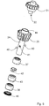
- FIG 5 the mounting and drive device together with the locking device for the inserted shafts of the tools is shown again in the form of an exploded view.
- the hollow shaft 24 can be seen, which extends through the third planet gear 25 and has the annular rotary bearing 44 on its upper side.
- the upper bearing 37 and the lower bearing 38 are provided for the rotatable mounting of the hollow shaft 24.
- the locking device for the inserted shafts which comprises a plurality of balls 40, which are resiliently mounted on or in the recesses 41 of the hollow shaft 24, is located between these two bearings.
- the C-shaped spring element 42 is provided, which at least partially surrounds the outside of the hollow shaft 24.
- the balls 40 are gripped by the C-shaped spring element 42 and pressed radially inwards from the outside by the spring force of the C-shaped spring element 42.
- a shaft of a tool of the first type or of the second type inserted into the holding and drive device is fixed in the axial direction by the spring-mounted balls 40.
- a circumferential sealing bellows 43 is arranged on the outside of the hollow shaft and protects the locking device against dirt, oil and grease.
- an end piece 46 is provided at the lower end of the holding and drive device in order to prevent food residues from penetrating into the bearing of the hollow shaft 24.
- Figure 6 shows a mounting and drive device with an inserted tool of the first type.
- the first shaft 47 of the tool of the first type has a first fitting piece 48 with a hexagonal profile, which is complementary to the first fitting profile 39 of the hollow shaft 24, which also has a hexagonal shape.
- the inserted first shaft 47 of the tool of the first type is therefore positively received by the first fitting profile 39 of the hollow shaft 24, so that a rotationally fixed coupling is produced between the hollow shaft 24 and the first shaft 47.
- Kneading hook shown as an example of a tool of the first type is therefore driven by the hollow shaft 24, which provides a high torque at a comparatively low rotational speed.
- the first shaft 47 of the tool of the first type has a circumferential groove 49 at the level of the locking device.
- the balls 40 When the tool of the first type is fully inserted into the hollow shaft 24, the balls 40 are pressed by the C-shaped spring element 42 into the circumferential groove 49, so that the first shaft 47 of the tool of the first type is locked in the axial direction. To release the first shaft 47 from the hollow shaft 24, a certain minimum force is required in order to press the balls 40 back against the spring force of the C-shaped spring element 42 into the associated recesses 41 in the hollow shaft 24 and then to be able to remove the tool.
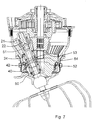
- FIG. 7 a mounting and drive device into which a second shaft 50 of a tool of the second type is inserted.
- the second shaft 50 has a round cross-sectional profile in its lower region, to which a second one only in the upper region Fit piece 51 is formed with a hexagonal profile.
- the second shaft 50 can be pushed through the hollow shaft 24 without the second shaft 50 coming into engagement with the hexagonal first fitting profile 39 of the hollow shaft 24.
- the second fitting piece 51 is positively received by the second fitting profile 45 of the coupling piece 22, so that a rotationally fixed coupling is formed between the second shaft 50 of the tool of the second type and the coupling piece 22 on the second planet gear 21.
- the tool of the second type is therefore driven by the second planet gear 21 and rotates within the hollow shaft 24 at a higher speed than the comparatively slowly rotating hollow shaft 24.
- a whisk is shown as an example of a tool of the second type.
- the inserted second shaft 50 of the tool of the second type has a groove 52 at the level of the locking device.
- the balls 40 are pressed into the groove 52 by the C-shaped spring element 42 from different sides.
- the second shaft 50 rotates within the hollow shaft 24 at a higher speed than the hollow shaft 24 itself.
- the balls 40 pressed radially inwards fulfill a double function here.
- the second shaft 50 of the tool of the second type is locked in the axial direction by the balls 40 pressed into the groove 52 and held in a stable manner within the holding and drive device.
- the balls 40 pressed inward form a rotary bearing for the second shaft 50 rotating at a higher speed relative to the hollow shaft 24.
- this rotary bearing can be a plain bearing, a roller bearing or a roller bearing for act the second wave 50.
- a minimum release force is required to push back the spring-loaded balls 40.
- the conical section 53 on the web above the groove 52 is designed as a flat conical section.
- the conical section 54 facing the balls 40 is designed to be relatively steep, so that a comparatively high minimum loosening force is required to pull out the tool.
- FIG 8 Another example of a locking device is shown which, in contrast to the locking device discussed so far, is attached to the lower end of the hollow shaft 24 is.
- the locking device consists of a circumferential sleeve 55 which has one or more pockets 56 for receiving the balls 40, the pockets 56 expanding conically upwards.
- the cuff 55 is with an in Figure 8 provided spring element, not shown, which presses the sleeve 55 in the direction of arrow 57 upwards against the hollow shaft 24. By means of this spring force, the balls 40 located in the conically shaped pockets 56 are pressed radially inward through the recess 41.
- the spring-loaded balls 40 snap into the circumferential groove 49 of the first shaft 47 and fix the first shaft 47 in the axial direction.
- the sleeve 55 is manually pulled downward in the direction of the arrow 58 against the spring force of the spring element. This gives the balls 40 in the pockets 56 more space and the first shaft 47 can be pulled out of the holding and driving device.
Landscapes
- Engineering & Computer Science (AREA)
- Mechanical Engineering (AREA)
- Food Science & Technology (AREA)
- Food-Manufacturing Devices (AREA)
Description
Die Erfindung betrifft eine Halterungs- und Antriebsvorrichtung für rotierbare Werkzeuge für eine Küchenmaschine. Des Weiteren betrifft die Erfindung eine Getriebeeinheit für eine Küchenmaschine mit einer Halterungs- und Antriebsvorrichtung für rotierbare Werkzeuge sowie eine Küchenmaschine mit einer Getriebeeinheit.The invention relates to a mounting and drive device for rotatable tools for a food processor. Furthermore, the invention relates to a gear unit for a food processor with a mounting and drive device for rotatable tools and a food processor with a gear unit.
In einer Küchenmaschine ist eine Halterungs- und Antriebsvorrichtung für rotierbare Werkzeuge vorgesehen, in die das jeweilige Werkzeug eingesteckt werden kann. Die Halterungs- und Antriebsvorrichtung muss das Werkzeug so haltern, dass es während des Betriebs der Küchenmaschine nicht herausgeschleudert werden kann.A holder and drive device for rotatable tools is provided in a kitchen machine, into which the respective tool can be inserted. The holder and drive device must hold the tool in such a way that it cannot be thrown out while the food processor is in operation.
In der deutschen Patentschrift
Die Schrift
Es ist Aufgabe der Erfindung, eine Halterungs- und Antriebseinheit für rotierbare Werkzeuge in einer Küchenmaschine bereitzustellen, die auch dann eine zuverlässige Halterung von Werkzeugen ermöglicht, wenn die Werkzeuge mit unterschiedlichen Drehgeschwindigkeiten angetrieben werden.It is an object of the invention to provide a mounting and drive unit for rotatable tools in a food processor that is reliable even then Tool holder is possible if the tools are driven at different speeds.
Die Lösung der gestellten Aufgabe gelingt durch Bereitstellen einer Halterungs- und Antriebsvorrichtung für rotierbare Werkzeuge für eine Küchenmaschine, wobei die Halterungs- und Antriebsvorrichtung eine rotierbare Hohlwelle mit einer ersten Passungsaufnahme zur Aufnahme eines ersten Typs von Werkzeugen und ein weiteres Kupplungsstück mit einer zweiten Passungsaufnahme zur Aufnahme eines zweiten Typs von Werkzeugen umfasst, das oberhalb der Hohlwelle rotierbar gelagert ist. Darüber hinaus umfasst die Halterungs- und Antriebsvorrichtung mindestens einen Anpresskörper, der an oder in mindestens einer zugehörigen Ausnehmung der Hohlwelle angeordnet ist, und mindestens ein Federelement, durch dessen Federkraft der mindestens eine Anpresskörper durch die zugehörige Ausnehmung in der Hohlwelle hindurch radial nach innen drückbar ist.The problem is solved by providing a holder and drive device for rotatable tools for a food processor, the holder and drive device having a rotatable hollow shaft with a first fit receptacle for receiving a first type of tools and a further coupling piece with a second fit receptacle for receiving of a second type of tools, which is rotatably mounted above the hollow shaft. In addition, the mounting and drive device comprises at least one pressing body, which is arranged on or in at least one associated recess of the hollow shaft, and at least one spring element, by the spring force of which the at least one pressing body can be pressed radially inward through the associated recess in the hollow shaft .
Die Halterungs- und Antriebsvorrichtung für rotierbare Werkzeuge umfasst zusätzlich zu der rotierbaren Hohlwelle, die einen ersten Typ von Werkzeugen antreiben kann, ein weiteres Kupplungsstück, das oberhalb der Hohlwelle rotierbar gelagert ist und zum Antrieb eines zweiten Typs von rotierbaren Werkzeugen ausgelegt ist. Dabei kann die rotierbare Hohlwelle mit einer anderen Geschwindigkeit als das weitere Kupplungsstück angetrieben werden, um auf diese Weise unterschiedliche Antriebsgeschwindigkeiten für unterschiedliche Typen von Werkzeugen bereitstellen zu können. Die rotierbare Hohlwelle und das weitere Kupplungsstück können dabei entweder mit gleicher Drehrichtung oder mit unterschiedlicher Drehrichtung angetrieben werden.In addition to the rotatable hollow shaft, which can drive a first type of tools, the mounting and drive device for rotatable tools comprises a further coupling piece which is rotatably mounted above the hollow shaft and is designed to drive a second type of rotatable tools. The rotatable hollow shaft can be driven at a different speed than the further coupling piece, in order in this way to be able to provide different drive speeds for different types of tools. The rotatable hollow shaft and the further coupling piece can be driven either with the same direction of rotation or with a different direction of rotation.
In Bezug auf die Halterungs- und Antriebsvorrichtung sollen die Begriffe "oben", "oberhalb", "unten" und "unterhalb" in Hinblick auf eine in eine Küchenmaschine eingebaute Halterungs- und Antriebsvorrichtung verstanden werden, wobei die Küchenmaschine zum bestimmungsgemäßen Gebrauch auf einer Arbeitsplatte steht.With regard to the holder and drive device, the terms “above”, “above”, “below” and “below” should be understood with regard to a holder and drive device installed in a kitchen machine, the kitchen machine being used as intended on a worktop stands.
Unabhängig von der jeweiligen Drehgeschwindigkeit und Drehrichtung sollen aber alle in die Halterungs- und Antriebsvorrichtung eingesetzten Werkzeuge nach dem Einsetzen zuverlässig arretiert werden, damit sie während des laufenden Betriebs nicht herausgeschleudert werden können. Hierzu weist die Hohlwelle mindestens eine Ausnehmung auf, in oder an der jeweils ein geeignet geformter Anpresskörper angeordnet ist, der mittels mindestens eines Federelements mit einer gewissen Federkraft radial nach innen gedrückt wird. Dabei kann das mindestens eine Federelement den oder die Anpresskörper entweder unmittelbar oder mittelbar über ein Zwischenstück radial nach innen drücken, beispielsweise mittels einer Manschette mit konisch zulaufenden Innenwänden, die durch das mindestens eine Federelement in axialer Richtung gegen die Anpresskörper gedrückt wird, so dass die Anpresskörper durch die Manschette nach innen gedrückt werden. Wenn eine Welle eines Werkzeugs in die Halterungs- und Antriebsvorrichtung eingeschoben wird, dann werden die Anpressköper durch die Ausnehmungen in der Hohlwelle hindurch gegen die Welle des jeweiligen Werkzeugs gedrückt, und das Werkzeug wird in axialer Richtung fixiert und arretiert. Das Werkzeug kann beispielsweise eine umlaufende Nut aufweisen, in die die Anpresskörper hineingedrückt werden und die Welle des Werkzeugs so fixieren. Die Arretierung der Welle des Werkzeugs in axialer Richtung funktioniert auch dann, wenn die Welle des Werkzeugs mit einer von der Hohlwelle verschiedenen Geschwindigkeit angetrieben wird. Beispielsweise wird ein Werkzeug des zweiten Typs, dessen Welle in die zweite Passungsaufnahme eingesteckt wird, durch das weitere Kupplungsstück mit einer von der Hohlwelle verschiedenen Drehgeschwindigkeit angetrieben. In diesem Fall rotiert die Welle des Werkzeugs vom zweiten Typ mit einer von der Hohlwelle abweichenden Geschwindigkeit. Auch eine Rotation mit unterschiedlicher Drehrichtung ist möglich. Auch in diesem Fall ermöglichen die federnd gelagerten Anpresskörper eine Arretierung der Welle in axialer Richtung, indem sie beispielsweise in eine umlaufende Rille des Werkzeugs des zweiten Typs gedrückt werden. Da sich die Welle des Werkzeugs des zweiten Typs relativ zu den Anpresskörpern dreht, wirken die gegen die Welle gedrückten Anpresskörper dabei zugleich als Drehlager für die rotierende Welle des zweiten Typs von Werkzeug. Die rotierende Welle wird also einerseits durch den Eingriff der Anpresskörper in die Rille fixiert und arretiert, andererseits wird dennoch eine freie Drehung der Welle innerhalb des durch die Anpresskörper gebildeten Drehlagers ermöglicht.Regardless of the respective speed and direction of rotation, all tools used in the mounting and drive device should be reliably locked after insertion so that they cannot be thrown out during operation. For this purpose, the hollow shaft has at least one recess, in or on which a suitably shaped pressing body is arranged, which is pressed radially inwards by means of at least one spring element with a certain spring force. The at least one spring element can press the pressure element (s) either radially inwards directly or indirectly via an intermediate piece, for example by means of a sleeve with conically tapering inner walls, which is pressed axially against the pressure element by the at least one spring element, so that the pressure element through the cuff. When a shaft of a tool is inserted into the holder and drive device, the pressing bodies are pressed through the recesses in the hollow shaft against the shaft of the respective tool, and the tool is fixed and locked in the axial direction. The tool can, for example, have a circumferential groove into which the pressing bodies are pressed and thus fix the shaft of the tool. The locking of the shaft of the tool in the axial direction also works when the shaft of the tool is driven at a speed different from the hollow shaft. For example, a tool of the second type, the shaft of which is inserted into the second fitting receptacle, is driven by the further coupling piece at a rotational speed different from the hollow shaft. In this case, the shaft of the second type tool rotates at a speed different from the hollow shaft. Rotation with different directions of rotation is also possible. In this case too, the resiliently mounted pressing bodies enable the shaft to be locked in the axial direction, for example by being pressed into a circumferential groove in the tool of the second type. Since the shaft of the tool of the second type rotates relative to the pressing bodies, the pressing bodies pressed against the shaft also act as rotary bearings for the rotating shaft of the second type of tool. The rotating shaft is thus fixed and locked on the one hand by the engagement of the pressing bodies in the groove, on the other hand a free rotation of the shaft is nevertheless made possible within the rotary bearing formed by the pressing bodies.
Eine erfindungsgemäße Getriebeeinheit für eine Küchenmaschine umfasst eine Halterungs- und Antriebsvorrichtung wie oben beschrieben, eine erste Planetengetriebestufe, wobei ein erstes Planetenrad der ersten Planetengetriebestufe mit der rotierbaren Hohlwelle verbunden ist und die rotierbare Hohlwelle antreibt, und eine zweite Planetengetriebestufe, wobei ein zweites Planetenrad der zweiten Planetengetriebestufe mit dem weiteren Kupplungsstück verbunden ist und das weitere Kupplungsstück antreibt. Dabei kann das erste Planetenrad der ersten Planetengetriebestufe die rotierbare Hohlwelle mit einer ersten Drehgeschwindigkeit antreiben, wohingegen das zweite Planetenrad der zweiten Planetengetriebestufe das weitere Kupplungsstück mit einer zweiten Drehgeschwindigkeit antreiben kann. Auf diese Weise können für unterschiedliche Werkzeuge mit unterschiedlicher Drehgeschwindigkeit vorgesehen werden, wobei die Halterungs- und Antriebsvorrichtung trotz der unterschiedlichen Drehgeschwindigkeiten eine zuverlässige Fixierung der Wellen der Werkzeuge ermöglicht.A gear unit according to the invention for a kitchen machine comprises a mounting and drive device as described above, a first planetary gear stage, a first planet gear of the first planetary gear stage being connected to the rotatable hollow shaft and driving the rotatable hollow shaft, and a second planetary gear stage, a second planet gear of the second Planetary gear stage is connected to the further coupling piece and drives the further coupling piece. The first planet gear of the first planetary gear stage can drive the rotatable hollow shaft at a first rotational speed, whereas the second planet gear of the second planetary gear stage can drive the further coupling piece at a second rotational speed. In this way, different tools can be provided with different speeds of rotation, the mounting and drive device, despite the different speeds of rotation, making it possible to reliably fix the shafts of the tools.
Vorzugsweise weist die Halterungs- und Antriebsvorrichtung eine Mehrzahl von Anpresskörpern auf, die in einer bestimmten Höhe der Hohlwelle um die Hohlwelle umlaufend angeordnet sind. Dadurch ist es möglich, eine eingesteckte Welle symmetrisch von unterschiedlichen Richtungen aus mittels der federnd gelagerten Anpresskörper zu fixieren. Dadurch wird eine symmetrische Fixierung und Arretierung der Welle erzielt, so dass Unwuchten vermieden werden.The holding and drive device preferably has a plurality of pressing bodies which are arranged around the hollow shaft at a certain height of the hollow shaft. This makes it possible to fix an inserted shaft symmetrically from different directions by means of the spring-loaded pressing body. This results in a symmetrical fixation and locking of the shaft so that unbalance is avoided.
Vorzugsweise ist die rotierbare Hohlwelle koaxial zu dem weiteren Kupplungsstück angeordnet. Vorzugsweise fällt die Achse einer von der rotierbaren Hohlwelle antreibbaren Welle eines Werkzeugs des ersten Typs mit der Achse einer von dem weiteren Kupplungsstück antreibbaren Welle eines Werkzeugs des zweiten Typs zusammen. Die Halterungs- und Antriebsvorrichtung weist eine gemeinsame Einstecköffnung auf, in die sowohl die Werkzeuge des ersten Typs als auch die Werkzeuge des zweiten Typs eingesteckt werden können. Die eingesteckten Werkzeuge gelangen entweder mit der Hohlwelle oder mit dem weiteren Kupplungsstück in Eingriff, wobei infolge der koaxialen Anordnung der Hohlwelle und des weiteren Kupplungsstücks die Drehachsen der beiden Typen von Werkzeugen übereinstimmen.The rotatable hollow shaft is preferably arranged coaxially with the further coupling piece. The axis of a shaft of a tool of the first type which can be driven by the rotatable hollow shaft coincides with the axis of a shaft of a tool of the second type which can be driven by the further coupling piece. The mounting and drive device has a common insertion opening into which both the tools of the first type and the tools of the second type can be inserted. The inserted tools come into engagement either with the hollow shaft or with the further coupling piece, where, due to the coaxial arrangement of the hollow shaft and the further coupling piece, the axes of rotation of the two types of tools match.
Vorzugsweise ist die Hohlwelle mit einer ersten Drehgeschwindigkeit antreibbar und das weitere Kupplungsstück ist mit einer von der ersten Drehgeschwindigkeit verschiedenen zweiten Drehgeschwindigkeit antreibbar. Innerhalb der Halterungs- und Antriebsvorrichtung können somit durch die Hohlwelle und das weitere Kupplungsstück unterschiedliche Antriebsgeschwindigkeiten bereitgestellt werden. Dabei können die Hohlwelle und das weitere Kupplungsstück mit gleicher Drehrichtung oder mit unterschiedlicher Drehrichtung angetrieben werden.The hollow shaft can preferably be driven at a first rotational speed and the further coupling piece can be driven at a second rotational speed that is different from the first rotational speed. Different drive speeds can thus be provided within the mounting and drive device by the hollow shaft and the further coupling piece. The hollow shaft and the further coupling piece can be driven with the same direction of rotation or with a different direction of rotation.
Vorzugsweise handelt es sich bei dem Werkzeug um ein Knet- oder Rührwerkzeug. Derartige Werkzeuge wie beispielsweise Rührer, Schneebesen, Knethaken etc. können in die Halterungs- und Antriebsvorrichtung der Küchenmaschine eingesteckt und rotierend angetrieben werden.The tool is preferably a kneading or stirring tool. Such tools such as stirrers, whisks, dough hooks etc. can be inserted into the mounting and drive device of the food processor and driven in rotation.
Vorzugsweise handelt es sich bei dem mindestens einen Anpresskörper um mindestens eine Kugel, die durch entsprechende Ausnehmungen in der Hohlwelle hindurch durch das mindestens eine Federelement radial nach innen drückbar ist. Die Kugeln können mittels des mindestens einen Federelements gegen die Welle des Werkzeugs gedrückt werden und beispielsweise in eine Nut oder in eine Rille des Werkzeugs hineingedrückt werden. Beim Herausziehen des Werkzeugs werden die Kugeln durch Aufbringen einer Kraft aus der Nut oder Rille herausgedrückt, um das Werkzeug wieder entnehmen zu können.The at least one pressing body is preferably at least one ball which can be pressed radially inwards through corresponding recesses in the hollow shaft through the at least one spring element. The balls can be pressed against the shaft of the tool by means of the at least one spring element and pressed, for example, into a groove or into a groove of the tool. When pulling out the tool, the balls are pressed out of the groove or groove by applying a force in order to be able to remove the tool again.
Vorzugsweise handelt es sich bei dem mindestens einen Anpresskörper um eine Mehrzahl von Wälzkörpern, die in einem Wälzkörperkäfig angeordnet sind. Durch den Wälzkörperkäfig können die Wälzkörper so gelagert werden, dass sie als Drehlager für eine eingesteckte Welle eines Werkzeugs dienen können. Dabei sind die Wälzkörper im Wälzkörperkäfig so gelagert, dass sie in radialer Richtung federnd nach innen gedrückt werden. Dabei können die Wälzkörper beispielsweise unmittelbar durch das mindestens eine Federelement nach innen gedrückt werden. Die Wälzkörper können aber beispielsweise auch mittelbar mittels einer Hülse oder Manschette mit konisch zulaufenden Innenwänden nach innen gedrückt werden, die durch das mindestens eine Federelement in axialer Richtung gedrückt wird.The at least one pressing body is preferably a plurality of rolling bodies which are arranged in a rolling body cage. The rolling element cage allows the rolling elements to be supported in such a way that they can serve as a rotary bearing for an inserted shaft of a tool. The rolling elements are mounted in the rolling element cage in such a way that they are pressed resiliently inwards in the radial direction. The rolling elements can be pressed inwards, for example, directly by the at least one spring element. However, the rolling elements can also be pressed inwards indirectly, for example, by means of a sleeve or sleeve with conically tapering inner walls, which is pressed in the axial direction by the at least one spring element.
Vorzugsweise handelt es sich bei dem mindestens einen Federelement um ein C-förmiges Federelement, das an der Außenseite der Hohlwelle angeordnet die Hohlwelle zumindest teilweise umschließt. Das C-förmige Federelement wird von außen auf die Hohlwelle aufgesteckt. Das C-förmige Federelement lässt sich einfach auf die Hohlwelle aufstecken und ermöglicht daher eine schnelle Montage. Vorzugsweise ist das an der Außenseite der Hohlwelle anliegende Federelement dazu ausgelegt, die Anpresskörper zu erfassen und von außen radial nach innen zu drücken.The at least one spring element is preferably a C-shaped spring element which, arranged on the outside of the hollow shaft, at least partially surrounds the hollow shaft. The C-shaped spring element is attached to the hollow shaft from the outside. The C-shaped spring element can be easily attached to the hollow shaft and therefore enables quick assembly. The spring element bearing on the outside of the hollow shaft is preferably designed to grip the pressing bodies and to press them radially inwards from the outside.
Vorzugsweise weist die Halterungs- und Antriebsvorrichtung ein oberes Lager und ein unteres Lager zur rotierbaren Lagerung der Hohlwelle auf. Mittels der zwei voneinander beabstandeten Lager können die auf die eingesteckten Werkzeuge und die Hohlwelle aufgebrachten Kräfte aufgenommen werden. Vorzugsweise ist der mindestens eine Anpresskörper auf einer bestimmten Höhe zwischen dem oberen Lager und dem unteren Lager um die Außenseite der Hohlwelle herum angeordnet. Zwischen dem unteren Lager und dem oberen Lager ist ausreichend Platz für die Anbringung der Arretiervorrichtung vorhanden.The mounting and drive device preferably has an upper bearing and a lower bearing for the rotatable mounting of the hollow shaft. The forces applied to the inserted tools and the hollow shaft can be absorbed by means of the two spaced apart bearings. The at least one pressing body is preferably arranged at a certain height between the upper bearing and the lower bearing around the outside of the hollow shaft. There is sufficient space between the lower bearing and the upper bearing for the attachment of the locking device.
Vorzugsweise ist die Hohlwelle für den Antrieb von Werkzeugen des ersten Typs ausgebildet, zu deren Betrieb ein vergleichsweise hohes Drehmoment bei vergleichsweise niedriger Drehzahl erforderlich ist. Die Hohlwelle wird von dem Getriebe der Küchenmaschine mit einer vergleichsweise niedrigen Drehgeschwindigkeit angetrieben und eignet sich daher zum Antrieb von Werkzeugen des ersten Typs, zu denen beispielsweise Knetwerkzeuge wie ein Knethaken gehören. Bei diesen Werkzeugen kommt es in erster Linie auf die Bereitstellung eines ausreichenden Drehmoments an.The hollow shaft is preferably designed to drive tools of the first type, the operation of which requires a comparatively high torque at a comparatively low speed. The hollow shaft is driven by the gear unit of the kitchen machine at a comparatively low rotational speed and is therefore suitable for driving tools of the first type, which include kneading tools such as a kneading hook, for example. With these tools, it is primarily a question of providing sufficient torque.
Vorzugsweise ist in die Hohlwelle eine Welle eines Werkzeugs des ersten Typs einschiebbar und das Werkzeug des ersten Typs ist durch die Hohlwelle antreibbar. Vorzugsweise ist in die Hohlwelle eine Welle eines Werkzeugs des ersten Typs einschiebbar, wobei ein an der Welle des Werkzeugs des ersten Typs angebrachtes erstes Passungsstück in der ersten Passungsaufnahme formschlüssig aufnehmbar ist. Durch die Aufnahme des ersten Passungsstücks in der komplementär dazu ausgebildeten ersten Passungsaufnahme in der Hohlwelle wird eine drehfeste Kupplung zwischen der Hohlwelle und der Welle des Werkzeugs des ersten Typs hergestellt, sodass das Werkzeug durch die Hohlwelle antreibbar ist. Dabei können das erste Passungsstück und die erste Passungsaufnahme ein geeignetes Passungsprofil aufweisen, beispielsweise ein polygonales Mitnahmeprofil, insbesondere ein Sechskantprofil.A shaft of a tool of the first type can preferably be inserted into the hollow shaft and the tool of the first type can be driven by the hollow shaft. A shaft of a tool of the first type can preferably be inserted into the hollow shaft, wherein a first fitting piece attached to the shaft of the tool of the first type can be received in a form-fitting manner in the first fitting receptacle. By accommodating the first fitting piece in the complementary first fitting receptacle in the hollow shaft, a rotationally fixed coupling between the Hollow shaft and the shaft of the tool of the first type are produced so that the tool can be driven by the hollow shaft. The first fitting piece and the first fitting receptacle can have a suitable fitting profile, for example a polygonal driving profile, in particular a hexagonal profile.
Vorzugsweise ist der mindestens eine Anpresskörper durch die Federkraft des mindestens einen Federelements radial nach innen gegen eine eingesteckte Welle eines Werkzeugs des ersten Typs drückbar. Vorzugsweise wirkt der mindestens eine radial nach innen gedrückte Anpresskörper als Arretierung in axialer Richtung für eine eingesteckte Welle eines Werkzeugs des ersten Typs. Durch die gegen die Welle gepressten Anpresskörper wird die Welle des ersten Werkzeugs in der eingesteckten Position fixiert. Insbesondere wird dadurch verhindert, dass das Werkzeug während des laufenden Betriebs herausgeschleudert werden kann.The at least one pressing body can preferably be pressed radially inward against an inserted shaft of a tool of the first type by the spring force of the at least one spring element. The at least one pressing body pressed radially inward preferably acts as a locking device in the axial direction for an inserted shaft of a tool of the first type. The pressing body pressed against the shaft fixes the shaft of the first tool in the inserted position. In particular, this prevents the tool from being thrown out during operation.
Vorzugsweise ist der mindestens eine Anpresskörper durch die Federkraft des mindestens einen Federelements in eine umlaufende Nut oder in mindestens eine Aussparung in einer eingesteckten Welle eines Werkzeugs des ersten Typs drückbar und dazu ausgelegt, das Werkzeug des ersten Typs in axialer Richtung zu fixieren. Das Werkzeug des ersten Typs steht über das erste Passungsstück mit der ersten Passungsaufnahme der Hohlwelle in Eingriff und wird daher durch die Hohlwelle angetrieben. Daher dreht sich die Welle des Werkzeugs des ersten Typs mit der gleichen Geschwindigkeit, mit der auch die Hohlwelle rotiert. Indem nun die federnd gelagerten Anpresskörper in eine umlaufende Nut oder in die mindestens eine Aussparung der Welle einrasten bzw. einschnappen, wird das Werkzeug des ersten Typs in der eingesteckten Position fixiert.The at least one pressing body can preferably be pressed into a circumferential groove or into at least one recess in an inserted shaft of a tool of the first type by the spring force of the at least one spring element and is designed to fix the tool of the first type in the axial direction. The tool of the first type engages with the first fitting receptacle of the hollow shaft via the first fitting piece and is therefore driven by the hollow shaft. Therefore, the shaft of the tool of the first type rotates at the same speed that the hollow shaft rotates. The tool of the first type is fixed in the inserted position by the fact that the spring-loaded pressing bodies snap or snap into a circumferential groove or into the at least one recess in the shaft.
Vorzugsweise erfolgt durch den mindestens einen radial nach innen gedrückten Anpresskörper eine Fixierung einer Welle eines Werkzeugs des ersten Typs, wobei das Werkzeug des ersten Typs nur durch Aufbringen einer Mindestlösekraft aus der Halterungs- und Antriebsvorrichtung herausziehbar ist. Zum Herausziehen des Werkzeugs muss die Federkraft überwunden werden, mit der die Anpresskörper gegen die Welle gepresst werden. Sofern die Welle eine umlaufende Rille aufweist, in die die Anpresskörper eingreifen, ist es außerdem erforderlich, die Anpresskörper entgegen der Federkraft des Federelements aus der Rille zu drücken. Hierfür ist eine gewisse Mindestlösekraft erforderlich.A shaft of a tool of the first type is preferably fixed by the at least one radially inward pressing body, the tool of the first type being extractable from the holding and drive device only by applying a minimum release force. To pull out the tool, the spring force with which the pressing bodies are pressed against the shaft must be overcome. If the shaft has a circumferential groove in which the pressing bodies engage, it is also necessary to press the pressing bodies against To push the spring force of the spring element out of the groove. A certain minimum dissolving power is required for this.
Vorzugsweise ist das weitere Kupplungsstück für den Antrieb von Werkzeugen des zweiten Typs ausgebildet, zu deren Betrieb ein vergleichsweise niedriges Drehmoment bei vergleichsweise hoher Drehzahl erforderlich ist. Das weitere Kupplungsstück wird durch das Getriebe der Küchenmaschine mit einer vergleichsweise hohen Drehgeschwindigkeit angetrieben und eignet sich daher zum Antrieb von Werkzeugen, bei denen es auf eine hohe Drehgeschwindigkeit und weniger auf ein hohes Drehmoment ankommt, beispielsweise zum Antrieb von Quirls oder Schneebesen.The further coupling piece is preferably designed for driving tools of the second type, for the operation of which a comparatively low torque at a comparatively high speed is required. The further coupling piece is driven by the gear unit of the kitchen machine at a comparatively high rotational speed and is therefore suitable for driving tools that require a high rotational speed and less a high torque, for example for driving whisk or whisk.
Vorzugsweise ist in das weitere Kupplungsstück durch die Hohlwelle hindurch eine Welle eines Werkzeugs des zweiten Typs einschiebbar und das Werkzeug des zweiten Typs ist durch das weitere Kupplungsstück antreibbar. Das weitere Kupplungsstück ist oberhalb der Hohlwelle angeordnet und rotiert während des Betriebs mit einer höheren Drehgeschwindigkeit als die Hohlwelle. Zur Kupplung des Werkzeugs des zweiten Typs mit dem weiteren Kupplungsstück wird die Welle des Werkzeugs des zweiten Typs durch die langsamer rotierende Hohlwelle hindurch in das weitere Kupplungsstück eingeschoben, um so eine drehfeste Kupplung mit dem weiteren Kupplungsstück auszubilden.A shaft of a tool of the second type can preferably be inserted into the further coupling piece through the hollow shaft and the tool of the second type can be driven through the further coupling piece. The further coupling piece is arranged above the hollow shaft and rotates at a higher rotational speed than the hollow shaft during operation. For coupling the tool of the second type with the further coupling piece, the shaft of the tool of the second type is inserted through the slower rotating hollow shaft into the further coupling piece, so as to form a rotationally fixed coupling with the further coupling piece.
Vorzugsweise ist in das weitere Kupplungsstück durch die Hohlwelle hindurch eine Welle eines Werkzeugs des zweiten Typs einschiebbar, wobei ein an der Welle des Werkzeugs des zweiten Typs angebrachtes zweites Passungsstück in der zweiten Passungsaufnahme formschlüssig aufnehmbar ist. Durch die Aufnahme des zweiten Passungsstücks in der dazu komplementär ausgebildete zweite Passungsaufnahme wird eine drehfeste Kupplung zwischen dem weiteren Kupplungsstück und der Welle des Werkzeugs des zweiten Typs hergestellt. Hierzu weisen das zweite Passungsstück und die zweite Passungsaufnahme vorzugsweise ein geeignetes Passungsprofil auf, beispielsweise ein polygonales Mitnahmeprofil, insbesondere ein Sechskantprofil.A shaft of a tool of the second type can preferably be inserted into the further coupling piece through the hollow shaft, a second fitting piece attached to the shaft of the tool of the second type being able to be received in a form-fitting manner in the second fitting receptacle. By accommodating the second fitting piece in the second fitting receptacle designed to be complementary thereto, a rotationally fixed coupling is produced between the further coupling piece and the shaft of the tool of the second type. For this purpose, the second fitting piece and the second fitting receptacle preferably have a suitable fitting profile, for example a polygonal driving profile, in particular a hexagonal profile.
Vorzugsweise ist eine durch das weitere Kupplungsstück angetriebene Welle eines Werkzeugs des zweiten Typs mit einer von der Drehgeschwindigkeit der Hohlwelle verschiedenen Drehgeschwindigkeit antreibbar. Daher rotiert die Welle des Werkzeugs des zweiten Typs innerhalb der Hohlwelle mit einer höheren Drehgeschwindigkeit als die Hohlwelle selbst.A shaft of a tool of the second type, which is driven by the further coupling piece, can preferably be driven at a rotational speed different from the rotational speed of the hollow shaft. Therefore the shaft of the tool rotates of the second type within the hollow shaft with a higher rotational speed than the hollow shaft itself.
Vorzugsweise wirkt der mindestens eine radial nach innen gedrückte Anpresskörper als Gleit-, Roll- oder Wälzlager für eine eingesteckte Welle eines Werkzeugs des zweiten Typs. Vorzugsweise ist der mindestens eine Anpresskörper durch die Federkraft des mindestens einen Federelements gegen eine eingesteckte Welle eines mit einer von der Hohlwelle abweichenden Drehgeschwindigkeit rotierenden Werkzeugs des zweiten Typs drückbar, wobei der mindestens eine radial nach innen gedrückte Anpresskörper als Gleit-, Roll- oder Wälzlager für die eingesteckte Welle des Werkzeugs des zweiten Typs wirkt. Da sich die Welle des Werkzeugs des zweiten Typs relativ zur Hohlwelle dreht, werden die Anpresskörper gegen eine sich drehende Welle gedrückt und wirken somit als Drehlager, insbesondere als Gleit-, Roll- oder Wälzlager für die Welle des Werkzeugs des zweiten Typs. Durch die von allen Seiten federnd angepressten Anpresskörper wird eine stabile Führung der rotierenden Welle erzielt.The at least one pressing body pressed radially inward preferably acts as a sliding, rolling or rolling bearing for an inserted shaft of a tool of the second type. The at least one pressing body can preferably be pressed by the spring force of the at least one spring element against an inserted shaft of a tool of the second type rotating with a rotational speed deviating from the hollow shaft, the at least one pressing body pressed radially inward as a sliding, rolling or rolling bearing for the inserted shaft of the tool of the second type acts. Since the shaft of the tool of the second type rotates relative to the hollow shaft, the pressing bodies are pressed against a rotating shaft and thus act as a rotary bearing, in particular as a slide, roller or roller bearing for the shaft of the tool of the second type. A stable guidance of the rotating shaft is achieved due to the pressing body being pressed on from all sides.
Vorzugsweise ist der mindestens eine Anpresskörper durch die Federkraft des mindestens einen Federelements gegen eine Rille in einer eingesteckten Welle eines Werkzeugs des zweiten Typs drückbar. Die federnd gelagerten Anpresskörper greifen dann in die Rille in der Welle des Werkzeugs des zweiten Typs ein, ermöglichen aber dennoch eine Drehung der Welle relativ zur Hohlwelle.The at least one pressing body can preferably be pressed against a groove in an inserted shaft of a tool of the second type by the spring force of the at least one spring element. The resiliently mounted pressing bodies then engage in the groove in the shaft of the tool of the second type, but nevertheless allow the shaft to rotate relative to the hollow shaft.
Vorzugsweise ist der mindestens eine Anpresskörper durch die Federkraft des mindestens einen Federelements gegen eine Rille in einer eingesteckten Welle eines Werkzeugs des zweiten Typs drückbar und dazu ausgelegt, das Werkzeug des zweiten Typs in axialer Richtung zu fixieren. Durch die gegen die Rille in der eingesteckten Welle gedrückten Anpresskörper wird die Welle in axialer Richtung fixiert und am Herausrutschen gehindert. Dennoch wird durch die von allen Seiten in die Rille gepressten Anpresskörper eine Rotation der Welle des Werkzeugs des zweiten Typs relativ zur Hohlwelle ermöglicht. Insofern dienen die federnd gelagerten Anpresskörper sowohl zur Fixierung der Welle in axialer Richtung als auch als Drehlager für die innerhalb der Hohlwelle rotierende Welle des Werkzeugs des zweiten Typs.The at least one pressing body can preferably be pressed against a groove in an inserted shaft of a tool of the second type by the spring force of the at least one spring element and is designed to fix the tool of the second type in the axial direction. The pressing body pressed against the groove in the inserted shaft fixes the shaft in the axial direction and prevents it from slipping out. Nevertheless, the pressing body pressed into the groove from all sides enables the shaft of the tool of the second type to rotate relative to the hollow shaft. In this respect, the resiliently mounted pressing bodies serve both for fixing the shaft in the axial direction and as a rotary bearing for the shaft of the tool of the second type rotating within the hollow shaft.
Vorzugsweise umfasst die Halterungs- und Antriebsvorrichtung eine Manschette mit konisch zulaufender Innenwandung, wobei das mindestens eine Federelement dazu ausgelegt ist, die Manschette in axialer Richtung gegen den mindestens einen Anpresskörper zu drücken, wobei der mindestens eine Anpresskörper durch die konisch zulaufende Innenwandung der federnd angedrückten Manschette radial nach innen drückbar ist.The holding and drive device preferably comprises a sleeve with a conically tapering inner wall, the at least one spring element being designed to press the sleeve in the axial direction against the at least one pressing body, the at least one pressing body through the conically tapering inner wall of the resiliently pressed sleeve can be pushed radially inwards.
Vorzugsweise umfasst die Halterungs- und Antriebsvorrichtung eine am unteren Ende der Hohlwelle angeordnete umlaufende Manschette mit mindestens einer zum unteren Ende der Hohlwelle hin konisch zulaufenden Tasche zur Aufnahme des mindestens einen Anpresskörpers, wobei das mindestens eine Federelement dazu ausgebildet ist, die umlaufende Manschette in axialer Richtung nach oben gegen das untere Ende der Hohlwelle zu drücken. Die umlaufende Manschette weist Taschen zur Halterung der Anpresskörper auf, die sich nach oben hin konisch aufweiten und in denen die Anpresskörper gelagert sind. Diese Manschette wird durch das mindestens eine Federelement in axialer Richtung nach oben gegen die Hohlwelle gedrückt.The holding and drive device preferably comprises a circumferential sleeve arranged at the lower end of the hollow shaft with at least one pocket that tapers conically towards the lower end of the hollow shaft, for receiving the at least one pressing body, the at least one spring element being designed to axially surround the circumferential sleeve to press upwards against the lower end of the hollow shaft. The circumferential sleeve has pockets for holding the pressing bodies, which expand conically upwards and in which the pressing bodies are mounted. This sleeve is pressed upwards by the at least one spring element in the axial direction against the hollow shaft.
Vorzugsweise ist das mindestens eine Federelement dazu ausgebildet, die umlaufende Manschette in axialer Richtung nach oben gegen das untere Ende der Hohlwelle zu drücken, wobei der in der mindestens einen Tasche befindliche mindestens eine Anpresskörper durch das mindestens eine Federelement infolge der konischen Ausbildung der mindestens einen Tasche radial nach innen drückbar ist. Wenn die Manschette durch das mindestens eine Federelement nach oben gedrückt wird, führt dies dazu, dass die Anpresskörper infolge der konischen Form der Taschen radial nach innen gedrückt werden.The at least one spring element is preferably designed to press the circumferential sleeve upward in the axial direction against the lower end of the hollow shaft, the at least one pressing body located in the at least one pocket being pressed by the at least one spring element as a result of the conical design of the at least one pocket can be pushed radially inwards. If the sleeve is pressed upwards by the at least one spring element, this leads to the pressure bodies being pressed radially inwards due to the conical shape of the pockets.
Vorzugsweise ist die umlaufende Manschette zum Lösen des mindestens einen Anpresskörpers in axialer Richtung entgegen einer Federkraft des mindestens einen Federelements von der Hohlwelle manuell nach unten ziehbar, so dass der in der mindestens einen konisch zulaufenden Tasche gelagerte mindestens eine Anpresskörper nicht mehr radial nach innen drückbar ist und ein in die Halterungs- und Antriebsvorrichtung eingestecktes Werkzeug entnehmbar ist. Indem die Manschette manuell nach unten gezogen wird, werden auch die konisch zulaufenden Taschen nach unten bewegt, sodass die darin gelagerten Anpresskörper mehr Platz zur Verfügung haben und nicht mehr radial nach innen gedrückt werden. Dadurch wird die eingesteckte Welle eines Werkzeugs freigegeben und das Werkzeug kann entnommen werden.Preferably, the circumferential sleeve for releasing the at least one pressing body in the axial direction against a spring force of the at least one spring element can be pulled manually downward from the hollow shaft, so that the at least one pressing body stored in the at least one conically tapering pocket can no longer be pressed radially inward and a tool inserted into the holder and drive device can be removed. By pulling the sleeve down manually, the tapered pockets are also moved downwards, so that the pressure bodies stored in them are more available have and are no longer pressed radially inwards. This releases the inserted shaft of a tool and the tool can be removed.
Weitere vorteilhafte Ausgestaltungen werden nachfolgend anhand mehrerer in den Zeichnungen dargestellten Ausführungsbeispielen, auf welche die Erfindung jedoch nicht beschränkt ist, näher beschrieben.Further advantageous embodiments are described in more detail below with reference to several exemplary embodiments shown in the drawings, to which the invention is not limited, however.
Es zeigt schematisch:
- Figur 1:
-
Fig. 1 zeigt eine Ansicht einer Küchenmaschine mit einer in den Arm der Küchenmaschine integrierten Getriebeeinheit. - Figur 2:
-
Fig. 2 zeigt eine schematische Darstellung der Getriebestufen einer Getriebeeinheit. - Figur 3:
-
Fig. 3 zeigt eine detaillierte Darstellung der Getriebeeinheit im Längsschnitt. - Figur 4:
-
Fig. 4 zeigt eine Halterungs- und Antriebsvorrichtung für rotierende Rühr- oder Knetwerkzeuge. - Figur 5:
-
Fig. 5 zeigt eine Explosionsdarstellung der Halterungs- und Antriebsvorrichtung zusammen mit der Arretiervorrichtung. - Figur 6:
-
Fig. 6 zeigt eine Halterungs- und Antriebsvorrichtung, in die ein Werkzeug des ersten Typs eingesteckt ist. - Figur 7:
-
Fig. 7 zeigt eine Halterungs- und Antriebsvorrichtung mit einem eingesteckten Werkzeug des zweiten Typs. - Figur 8:
-
Fig. 8 zeigt ein weiteres Beispiel einer Arretiervorrichtung, die am unteren Ende der Hohlwelle angebracht ist.
- Figure 1:
-
Fig. 1 shows a view of a food processor with a gear unit integrated into the arm of the food processor. - Figure 2:
-
Fig. 2 shows a schematic representation of the gear stages of a gear unit. - Figure 3:
-
Fig. 3 shows a detailed representation of the gear unit in longitudinal section. - Figure 4:
-
Fig. 4 shows a mounting and drive device for rotating stirring or kneading tools. - Figure 5:
-
Fig. 5 shows an exploded view of the mounting and drive device together with the locking device. - Figure 6:
-
Fig. 6 shows a holder and drive device, in which a tool of the first type is inserted. - Figure 7:
-
Fig. 7 shows a mounting and drive device with an inserted tool of the second type. - Figure 8:
-
Fig. 8 shows another example of a locking device which is attached to the lower end of the hollow shaft.
Bei der nachfolgenden Beschreibung von bevorzugten Ausführungsformen der vorliegenden Erfindung bezeichnen gleiche Bezugszeichen gleiche oder vergleichbare Komponenten.In the following description of preferred embodiments of the present invention, identical reference symbols designate identical or comparable components.
In
In
Das dritte Sonnenrad 14 der dritten Getriebestufe 9 ist mit der antriebsseitigen Eingangswelle 12 verbunden. Wenn sich die Riemenscheibe 11 dreht, wird daher auch das dritte Sonnenrad 14 in Rotation versetzt. Die dritte Getriebestufe 9 umfasst außerdem mindestens ein drittes Planetenrad 15, das sowohl mit dem dritten Sonnenrad 14 als auch mit dem zweiten innenverzahnten Zahnkranz 16 kämmt, der an der Innenseite des Gehäuses 13 angebracht bzw. angeformt ist. Das mindestens eine dritte Planetenrad 15 ist an einem Planetenträger 17 gelagert, der mit der abtriebsseitigen Ausgangswelle 18 verbunden ist, die den oberen Abschnitt einer zentralen Welle bildet. Die abtriebsseitige Ausgangswelle 18 wird an der Oberseite der Getriebeeinheit 4 als Zapfwelle zur Verfügung gestellt und verläuft koaxial zur antriebsseitigen Eingangswelle 12, die als Hohlwelle ausgebildet ist und die abtriebsseitige Ausgangswelle 18 konzentrisch umschließt. Wenn das dritte Sonnenrad 14 in Rotation versetzt wird, bewegt sich das mindestens eine dritte Planetenrad 15 um das dritte Sonnenrad 14 herum und versetzt so den Planetenträger 17 in Rotation, der mit der abtriebsseitigen Ausgangswelle 18 verbunden ist. Dabei ist die Rotationsgeschwindigkeit des Planetenträgers 17 in der Regel geringer als die Rotationsgeschwindigkeit der antriebsseitigen Eingangswelle 12. Die abtriebsseitige Ausgangswelle 18 kann daher zum Antrieb von Aufsätzen verwendet werden, die eine vergleichsweise geringe Rotationsgeschwindigkeit benötigen, beispielsweise zum Antrieb eines Würfelschneiders oder einer Zitruspresse. Durch das Bereitstellen von mehreren koaxial zueinander ausgebildeten Zapfwellen an der Oberseite der Getriebeeinheit 4 können verschiedene Zubehörteile mit unterschiedlichen Anforderungen in Bezug auf Rotationsgeschwindigkeit und Drehmoment angetrieben werden.The
Die abtriebsseitige Ausgangswelle 18 treibt darüber hinaus das zweite Sonnenrad 19 der zweiten Getriebestufe 8 sowie das erste Sonnenrad 20 der ersten Getriebestufe 7 an, die in dem in
Infolge der Kegelradgeometrie verläuft die Ache 27 des Kupplungsstücks 22 und der Hohlwelle 24 schräg geneigt zur zentralen Achse 28 der Getriebeeinheit 4. Wenn das erste Planetenrad 25 durch das erste Sonnenrad 20 angetrieben wird, wird das erste Planetenrad 25 am ersten innenverzahnten Zahnkranz 26 abgewälzt. Das erste Planetenrad 25 bewegt sich um das erste Sonnenrad 20 herum und rotiert dabei um die eigene Achse. Insofern bewegen sich das Kupplungsstück 22 und die Hohlwelle 24 in einer Taumelbewegung rund um die zentrale Achse 28 der Getriebeeinheit 4, wobei das Kupplungsstück 22 und die Hohlwelle 24 dabei mit unterschiedlichen Geschwindigkeiten um die eigene Achse rotieren. Das Kupplungsstück 22 und die Hohlwelle 24 können entweder mit übereinstimmender oder mit unterschiedlicher Drehrichtung angetrieben werden. Dabei hängt es von den Zahnzahlen von zweitem Planetenrad 21, zweitem Sonnenrad 19, erstem Planetenrad 25 und erstem Sonnenrad 20 ab, ob das Kupplungsstück 22 und die Hohlwelle 24 mit gleicher oder mit unterschiedlicher Drehrichtung angetrieben werden.As a result of the bevel gear geometry, the
Sowohl das Kupplungsstück 22 als auch die Hohlwelle 24 können von der Unterseite der Getriebeeinheit 4 aus zum Antrieb von in die Getriebeeinheit 4 eingesteckten Knet- und Rührwerkzeugen genutzt werden, mit denen in der Rührschüssel 2 befindliches Rührgut aufgeschlagen, durchmischt bzw. geknetet werden kann. Das Kupplungsstück 22 rotiert mit höherer Geschwindigkeit als die Hohlwelle 24 und eignet sich daher insbesondere zum Antrieb eines Schneebesens. Dagegen stellt die mit langsamerer Drehgeschwindigkeit rotierende Hohlwelle 24 ein deutlich größeres Drehmoment zur Verfügung und eignet sich daher insbesondere zum Antrieb eines Knethakens, mit dem auch schwere Teige verarbeitet werden können. Durch die Bereitstellung des Kupplungsstücks 22 und der Hohlwelle 24 können verschiedene Rühr- und Knetwerkzeuge mit jeweils passender Geschwindigkeit und passender Drehrichtung und passendem Drehmoment angetrieben werden.Both the
Alternativ dazu könnten als Zahnräder der Planetengetriebestufen auch Stirnräder anstelle von Kegelrädern verwendet werden. in diesem Fall würden die Drehachsen der Planetenräder parallel zur zentralen Achse der Getriebeeinheit stehen und zusammen mit der rotierbaren Trägereinheit um die zentrale Achse der Getriebeeinheit umlaufen.Alternatively, spur gears instead of bevel gears could also be used as gears of the planetary gear stages. in this case the axes of rotation of the planet gears would be parallel to the central axis of the gear unit and would rotate together with the rotatable carrier unit around the central axis of the gear unit.
Wenn das erste Planetenrad 25 angetrieben vom ersten Sonnenrad 20 am ersten innenverzahnten Zahnkranz 26 abgewälzt wird, wird durch diesen Umlauf des ersten Planetenrads 25 die rotierbare Trägereinheit 23 angetrieben und in eine Rotationsbewegung versetzt. In der rotierbaren Trägereinheit 23 sind das Kupplungsstück 22 und die Hohlwelle 24 jeweils rotierbar gelagert, die daher mit der rotierbaren Trägereinheit 23 mitrotieren. Die rotierbare Trägereinheit 23 ist mit der abtriebsseitigen Ausgangswelle 29 verbunden, die durch die rotierbare Trägereinheit 23 in eine vergleichsweise langsame Rotation versetzt wird. Die abtriebsseitige Ausgangswelle 29 stellt den unteren Abschnitt der zentralen Welle der Getriebeeinheit 4 dar und ist über ein Drehlager 30 mit der abtriebsseitigen Ausgangswelle 18 gekoppelt. Die abtriebsseitige Ausgangswelle 29 kann an der Unterseite der Getriebeeinheit 4 als Zapfwelle für Zusatzgeräte genutzt werden, die eine vergleichsweise langsam rotierende Antriebswelle benötigen. Beispielsweise kann die abtriebsseitige Ausgangswelle 29 zum Antrieb eines Fleischwolfs, einer Getreidemühle, eines Pastavorsatzes, eines Eisbereiters etc. genutzt werden.When the
Wie aus
Anhand von
In
Die Hohlwelle 24 kann zum Antrieb einer in die Hohlwelle eingesteckten ersten Welle eines Werkzeugs des ersten Typs dienen. Hierzu ist die Hohlwelle 24 als Kupplungsstück ausgebildet und weist ein erstes Passungsprofil 39 auf, beispielsweise ein sechseckiges Passungsprofil. Wenn die erste Welle des Werkzeugs des ersten Typs ein Passungsstück aufweist, das zum ersten Passungsprofil 39 komplementär ist und beim Einschieben in die Hohlwelle 24 von dem ersten Passungsprofil 39 formschlüssig umfasst wird, dann wird zwischen der Hohlwelle 24 und der eingesteckten ersten Welle des Werkzeugs des ersten Typs eine drehfeste Kupplung ausgebildet. Das Werkzeug des ersten Typs kann dann durch die Hohlwelle 24 angetrieben werden.The
Zur Arretierung der eingesteckten Welle des Werkzeugs des ersten Typs umfasst die in
Zur Bereitstellung eines weiteren Gangs mit einer schnelleren Umlaufgeschwindigkeit ist oberhalb der Hohlwelle 24 und des ersten Planetenrades 25 das zweite Planetenrad 21 angeordnet, das mit dem zweiten Sonnenrad 19 in Eingriff steht und durch dieses angetrieben wird. Zur rotierbaren Lagerung des zweiten Planetenrades 21 weist die Hohlwelle 24 an ihrem oberen Ende ein ringförmiges Drehlager 44 auf, auf das das zweite Planetenrad 21 rotierbar aufgesteckt ist. Das zweite Planetenrad 21 ist daher koaxial zur Hohlwelle 24 und zum ersten Planetenrad 25 ausgebildet. Das zweite Planetenrad 21 folgt zum einen der Drehbewegung der rotierbaren Trägereinheit 23 um die zentrale Achse des Getriebes und führt andererseits eine Eigenrotation um die Achse 27 aus, wobei sich die Rotationsgeschwindigkeit des zweiten Planetenrades 21 von der Rotationsgeschwindigkeit des ersten Planetenrades 25 unterscheidet. Beispielsweise kann durch das zweite Planetenrad 21 ein besonders schneller Gang zum Antrieb von Rühr- und Knetwerkzeugen zur Verfügung gestellt werden. Im zweiten Planetenrad 21 ist ein Kupplungsstück 22 angeordnet, in das eine zweite Welle eines Werkstücks des zweiten Typs eingesteckt werden kann. Hierzu weist das Kupplungsstück 22 ein zweites Passungsprofil 45 auf, in das ein entsprechend geformtes Passungsstück an der zweiten Welle des Werkzeugs des zweiten Typs formschlüssig eingeschoben werden kann. Die zweite Welle des Werkzeugs des zweiten Typs wird dazu mit dem zweiten Passungsstück durch die Hohlwelle 24 und das erste Passungsprofil 39 hindurch in das zweite Passungsprofil 45 eingesteckt. Auf diese Weise kann eine drehfeste Kupplung zwischen dem zweiten Planetenrad 21 und der zweiten Welle des Werkzeugs des zweiten Typs hergestellt werden. Die zweite Welle des Werkzeugs des zweiten Typs wird dabei nicht vom ersten Passungsprofil 39 der Hohlwelle 24 erfasst. Stattdessen wird die zweite Welle des Werkzeugs des zweiten Typs durch das schneller drehende zweite Planetenrad 21 angetrieben, so dass durch das zweite Planetenrad 21 eine im Vergleich zur Hohlwelle 24 erhöhte Rotationsgeschwindigkeit zur Verfügung gestellt werden kann.To provide another gear with a faster rotational speed, the
Die in
Bei der in
Dabei eignet sich die Hohlwelle 24 insbesondere zum Antrieb von Werkzeugen, die ein hohes Drehmoment bei vergleichsweise niedriger Drehgeschwindigkeit benötigen, also beispielsweise zum Antrieb von Knetwerkzeugen zum Kneten von Teigen. Im Gegensatz dazu wird der durch das zweite Planetenrad 21 bereitgestellte Antrieb mit hoher Drehgeschwindigkeit und geringem Drehmoment beispielsweise zum Antrieb eines Schneebesens verwendet, der zum schnellen Aufschlagen von Sahne oder Eiweiß eine vergleichsweise hohe Drehgeschwindigkeit benötigt.The
In
Im Vergleich dazu zeigt
Die eingesteckte zweite Welle 50 des Werkzeugs des zweiten Typs weist auf Höhe der Arretiervorrichtung eine Rille 52 auf. Wenn die zweite Welle 50 vollständig in die Halterungs- und Antriebsvorrichtung eingeschoben ist, werden die Kugeln 40 durch das C-förmige Federelement 42 von verschiedenen Seiten aus in die Rille 52 gedrückt. Die zweite Welle 50 dreht sich innerhalb der Hohlwelle 24 mit einer höheren Geschwindigkeit als die Hohlwelle 24 selbst. Insofern erfüllen die radial nach innen gedrückten Kugeln 40 hier eine doppelte Funktion. Zum einen wird die zweite Welle 50 des Werkzeugs des zweiten Typs durch die in die Rille 52 gedrückten Kugeln 40 in axialer Richtung arretiert und innerhalb der Halterungs- und Antriebsvorrichtung stabil gehaltert. Zum andern bilden die nach innen gedrückten Kugeln 40 ein Drehlager für die relativ zur Hohlwelle 24 mit höherer Geschwindigkeit rotierende zweite Welle 50. Je nach Art der Lagerung der Kugeln 40 kann es sich bei diesem Drehlager um ein Gleitlager, um ein Rolllager oder ein Wälzlager für die zweite Welle 50 handeln. Um die zweite Welle 50 aus der Arretiervorrichtung zu lösen, ist eine Mindestlösekraft erforderlich, um die federnd gelagerten Kugeln 40 zurückzudrücken. Damit das Einschieben der zweiten Welle 50 in die Arretiervorrichtung erleichtert wird, ist der konische Abschnitt 53 am Steg oberhalb der Rille 52 als flacher konischer Abschnitt ausgebildet. Dagegen ist der den Kugeln 40 zugewandte konische Abschnitt 54 relativ steil ausgebildet, damit eine vergleichsweise hohe Mindestlösekraft zum Herausziehen des Werkzeugs erforderlich ist.The inserted
In
- 11
- KüchenmaschineFood processor
- 22nd
- RührschüsselMixing bowl
- 33rd
- Arm der KüchenmaschineArm of the food processor
- 44th
- GetriebeeinheitGear unit
- 55
- koaxiale Ausgangswellencoaxial output shafts
- 66
- Rühr- oder KnetwerkzeugStirring or kneading tools
- 77
- erste Getriebestufefirst gear stage
- 88th
- zweite Getriebestufesecond gear stage
- 99
- dritte Getriebestufethird gear stage
- 1010th
- vierte Getriebestufefourth gear stage
- 1111
- RiemenscheibePulley
- 1212th
- antriebsseitige Eingangswelleinput shaft on the drive side
- 1313
- Gehäusecasing
- 1414
- drittes Sonnenradthird sun gear
- 1515
- drittes Planetenradthird planet gear
- 1616
- zweiter innenverzahnter Zahnkranzsecond internally toothed ring gear
- 1717th
- PlanetenträgerPlanet carrier
- 1818th
- abtriebsseitige Ausgangswelleoutput shaft
- 1919th
- zweites Sonnenradsecond sun gear
- 2020
- erstes Sonnenradfirst sun gear
- 2121st
- zweites Planetenradsecond planet gear
- 2222
- KupplungsstückCoupling piece
- 2323
- rotierbare Trägereinheitrotatable carrier unit
- 2424th
- HohlwelleHollow shaft
- 2525th
- erstes Planetenradfirst planet gear
- 2626
- erster innenverzahnter Zahnkranzfirst internally toothed ring gear
- 2727
-
Achse des Kupplungsstücks 22 und der Hohlwelle 24Axis of the
coupling piece 22 and thehollow shaft 24 - 2828
- zentrale Achsecentral axis
- 2929
- abtriebsseitige Ausgangswelleoutput shaft
- 3030th
- DrehlagerPivot bearing
- 3131
- Wälzlagerroller bearing
- 3232
- Wälzlagerroller bearing
- 3333
- MitnahmeprofilTake-away profile
- 3434
- AxiallagerThrust bearing
- 3535
- FührungstrichterLeadership funnel
- 3636
- Wälzlagerroller bearing
- 3737
- oberes Lagerupper camp
- 3838
- unteres Lagerlower bearing
- 3939
- erstes Passungsprofilfirst fit profile
- 4040
- KugelBullet
- 4141
- AusnehmungRecess
- 4242
- FederelementSpring element
- 4343
- DichtungsbalgSealing bellows
- 4444
- ringförmiges Drehlagerring-shaped pivot bearing
- 4545
- zweites Passungsprofilsecond fit profile
- 4646
- AbschlussstückEnd piece
- 4747
- erste Welle eines Werkzeugs des ersten Typsfirst shaft of a tool of the first type
- 4848
- erstes Passungsstückfirst fitting piece
- 4949
- umlaufende Nutcircumferential groove
- 5050
- zweite Welle eines Werkzeugs des zweiten Typssecond shaft of a tool of the second type
- 5151
- zweites Passungsstücksecond fitting piece
- 5252
- Rillegroove
- 5353
- flacher konischer Abschnittflat conical section
- 5454
- steiler konischer Abschnittsteep conical section
- 5555
- Manschettecuff
- 5656
- konisch zulaufende Taschetapered pocket
- 5757
- Pfeilarrow
- 5858
- Pfeilarrow
Claims (15)
- Mounting and drive device for rotatable tools for a food processor (1), wherein the mounting and drive device has:a rotatable hollow shaft (24) with a first fitting receptacle (39) for receiving a first type of tools, and a further coupling piece (22) with a second fitting receptacle (45) for receiving a second type of tools, which is mounted rotatably above the hollow shaft (24),characterised byat least one press-on element (40) which is arranged on or in at least one associated cut-out (41) of the hollow shaft (24), andat least one spring element (42), by means of the elastic force of which the at least one press-on element (40) can be pushed radially inward through the associated cut-out (41) in the hollow shaft (24).
- Mounting and drive device according to claim 1, characterised in that the rotatable hollow shaft (24) is arranged coaxially with respect to the further coupling piece (22).
- Mounting and drive device according to claim 1 or claim 2, characterised in that the at least one spring element (42) is a C-shaped spring element which is arranged on the exterior of the hollow shaft (24) and at least partially encloses the hollow shaft (24).
- Mounting and drive device according to one of claims 1 to 3, characterised in that the hollow shaft (24) is embodied for the drive of tools of the first type, for the operation of which a comparatively high torque with a comparatively low rotational speed is required.
- Mounting and drive device according to one of claims 1 to 4, characterised in that a shaft of a tool of the first type can be inserted into the hollow shaft (24), wherein a first fitting piece (48) attached to the shaft of the tool of the first type can be received in the first fitting receptacle (39) in a form-fitting manner.
- Mounting and drive device according to one of claims 1 to 5, characterised in that the at least one press-on element (40) pushed radially inward acts as a stop in the axial direction for an inserted shaft (47) of a tool of the first type.
- Mounting and drive device according to one of claims 1 to 6, characterised in that the at least one press-on element (40) can be pushed into a peripheral groove (49) or into at least one cut-out in an inserted shaft (47) of a tool of the first type by means of the spring force of the at least one spring element (42) and is designed to fix the tool of the first type in the axial direction.
- Mounting and drive device according to one of claims 1 to 7, characterised in that the further coupling piece (22) is embodied for the drive of tools of the second type, for the operation of which a comparatively low torque with a comparatively high rotational speed is required.
- Mounting and drive device according to one of claims 1 to 8, characterised in that a shaft (50) of a tool of the second type can be inserted into the further coupling piece (22) through the hollow shaft (24), wherein a second fitting piece (51) attached to the shaft (50) of the tool of the second type can be received in the second fitting receptacle (45) in a form-fitting manner.
- Mounting and drive device according to one of claims 1 to 9, characterised in that the at least one press-on element (40) pushed radially inward acts as a sliding, rolling or roller bearing for an inserted shaft (50) of a tool of the second type.
- Mounting and drive device according to one of claims 1 to 10, characterised in that the at least one press-on element (40) can be pushed by means of the spring force of the at least one spring element (42) against an inserted shaft (50) of a tool of the second type which rotates at a rotational speed which differs from the hollow shaft (24), wherein the at least one press-on element (40) which is pushed radially inward acts as a sliding, rolling or roller bearing for the inserted shaft (50) of the tool of the second type.
- Mounting and drive device according to one of claims 1 to 11, characterised in that the at least one press-on element (40) can be pushed by means of the spring force of the at least one spring element (42) against a channel (52) in an inserted shaft (50) of a tool of the second type and is designed to fix the tool of the second type in the axial direction.
- Mounting and drive device according to one of claims 1 to 12, characterised in that the mounting and drive device comprises a circumferential collar (55) arranged at the lower end of the hollow shaft (24) with at least one pocket (56), which runs conically toward the lower end of the hollow shaft (24), in order to receive the at least one press-on element (40), wherein the at least one spring element is embodied to push the circumferential collar (55) in the axial direction upward against the lower end of the hollow shaft (24).
- Transmission unit (4) for a food processor (1), which has a mounting and drive device according to one of claims 1 to 13, a first planetary gear stage (7), wherein a first planetary wheel (25) of the first planetary gear stage (7) is connected to the rotatable hollow shaft (24) and drives the rotatable hollow shaft (24),
a second planetary gear stage (8), wherein a second planetary wheel (21) of the second planetary gear stage (8) is connected to the further coupling piece (22) and drives the further coupling piece (22). - A food processor (1), which has a transmission unit (4) according to claim 14.
Priority Applications (1)
| Application Number | Priority Date | Filing Date | Title |
|---|---|---|---|
| SI201730335T SI3503780T1 (en) | 2016-08-26 | 2017-08-03 | Mounting and drive device for tools in a food processor |
Applications Claiming Priority (2)
| Application Number | Priority Date | Filing Date | Title |
|---|---|---|---|
| DE102016216107.5A DE102016216107A1 (en) | 2016-08-26 | 2016-08-26 | Holding and driving device for tools in a food processor |
| PCT/EP2017/069614 WO2018036773A1 (en) | 2016-08-26 | 2017-08-03 | Mounting and drive device for tools in a food processor |
Publications (2)
| Publication Number | Publication Date |
|---|---|
| EP3503780A1 EP3503780A1 (en) | 2019-07-03 |
| EP3503780B1 true EP3503780B1 (en) | 2020-07-08 |
Family
ID=59520909
Family Applications (1)
| Application Number | Title | Priority Date | Filing Date |
|---|---|---|---|
| EP17748476.3A Active EP3503780B1 (en) | 2016-08-26 | 2017-08-03 | Mounting and drive device for tools in a food processor |
Country Status (4)
| Country | Link |
|---|---|
| EP (1) | EP3503780B1 (en) |
| DE (1) | DE102016216107A1 (en) |
| SI (1) | SI3503780T1 (en) |
| WO (1) | WO2018036773A1 (en) |
Families Citing this family (1)
| Publication number | Priority date | Publication date | Assignee | Title |
|---|---|---|---|---|
| EP4241635A1 (en) * | 2022-03-10 | 2023-09-13 | BSH Hausgeräte GmbH | Torque output component of a gear system for a kitchen machine, drive unit and and kitchen machine |
Family Cites Families (3)
| Publication number | Priority date | Publication date | Assignee | Title |
|---|---|---|---|---|
| DE1021986B (en) | 1955-01-24 | 1958-01-02 | Siemens Ag | Kitchen motor with stirring and kneading tools that can be alternately connected to its gearbox |
| DE2551842C3 (en) | 1975-11-19 | 1979-03-01 | Bosch-Siemens Hausgeraete Gmbh, 7000 Stuttgart | Electrically operated drive unit, in particular for kitchen machines or the like |
| DE102005040544A1 (en) * | 2005-08-26 | 2007-03-01 | BSH Bosch und Siemens Hausgeräte GmbH | Kitchen appliance with a reinforced electric motor-gear stage arrangement and method for manufacturing an electromotive kitchen appliance |
-
2016
- 2016-08-26 DE DE102016216107.5A patent/DE102016216107A1/en not_active Ceased
-
2017
- 2017-08-03 WO PCT/EP2017/069614 patent/WO2018036773A1/en unknown
- 2017-08-03 EP EP17748476.3A patent/EP3503780B1/en active Active
- 2017-08-03 SI SI201730335T patent/SI3503780T1/en unknown
Non-Patent Citations (1)
| Title |
|---|
| None * |
Also Published As
| Publication number | Publication date |
|---|---|
| WO2018036773A1 (en) | 2018-03-01 |
| SI3503780T1 (en) | 2020-08-31 |
| DE102016216107A1 (en) | 2018-03-01 |
| EP3503780A1 (en) | 2019-07-03 |
Similar Documents
| Publication | Publication Date | Title |
|---|---|---|
| DE102012206162B4 (en) | Food processor with a three-stage planetary gear | |
| EP3503782B1 (en) | Transmission unit for a food processor | |
| DE60208910T2 (en) | KITCHEN MACHINE WITH DIFFERENT TOOLS | |
| DE2551842A1 (en) | ELECTRIC MOTOR DRIVE UNIT, IN PARTICULAR FOR KITCHEN MACHINES OR THE LIKE. | |
| EP0221392B1 (en) | Supplementary device for an electrical food processor | |
| DE4414415C1 (en) | Attachment for an electrically operated hand mixer | |
| EP0292664B1 (en) | Tool for food processing | |
| EP3503780B1 (en) | Mounting and drive device for tools in a food processor | |
| DE19756923A1 (en) | Gear device | |
| EP0570677B1 (en) | Chopping and mixing tool for multi-purpose food processor | |
| EP0570758B1 (en) | Mixing and kneading device for multi-purpose food processor | |
| EP3287056B1 (en) | Multifunctional coupling device for a kitchen appliance | |
| EP3503781B1 (en) | Gear unit having a plurality of drive speeds | |
| DE102017213778B4 (en) | Implement for stirring or chopping foodstuffs | |
| EP3185736B1 (en) | Gearing for a food processor | |
| EP2432357B1 (en) | Kitchen appliance comprising a planetary gear | |
| DE4126516C1 (en) | kitchen food processor with exchangeable implements - has drive shaft with at least one coupling element and connectable to variable speed gearing and snap locking piece | |
| EP3432767B1 (en) | Peeling rotor | |
| DE1219643B (en) | Household appliance with a tool head for driving several stirring tools or the like. | |
| CH527563A (en) | Power kneader for doughs | |
| DE9205004U1 (en) | Food processing equipment | |
| EP2114225B1 (en) | Sliding bearing for a household appliance | |
| DE102007005110B4 (en) | Food processor with intermediate gear | |
| DE1186588B (en) | Gearboxes for kitchen machines | |
| DE10244714A1 (en) | Bearing for food mixer has cylindrical bush with prelubricated annular grooves to receive rotary implement connector |
Legal Events
| Date | Code | Title | Description |
|---|---|---|---|
| STAA | Information on the status of an ep patent application or granted ep patent |
Free format text: STATUS: UNKNOWN |
|
| STAA | Information on the status of an ep patent application or granted ep patent |
Free format text: STATUS: THE INTERNATIONAL PUBLICATION HAS BEEN MADE |
|
| PUAI | Public reference made under article 153(3) epc to a published international application that has entered the european phase |
Free format text: ORIGINAL CODE: 0009012 |
|
| STAA | Information on the status of an ep patent application or granted ep patent |
Free format text: STATUS: REQUEST FOR EXAMINATION WAS MADE |
|
| 17P | Request for examination filed |
Effective date: 20190326 |
|
| AK | Designated contracting states |
Kind code of ref document: A1 Designated state(s): AL AT BE BG CH CY CZ DE DK EE ES FI FR GB GR HR HU IE IS IT LI LT LU LV MC MK MT NL NO PL PT RO RS SE SI SK SM TR |
|
| AX | Request for extension of the european patent |
Extension state: BA ME |
|
| DAV | Request for validation of the european patent (deleted) | ||
| DAX | Request for extension of the european patent (deleted) | ||
| GRAP | Despatch of communication of intention to grant a patent |
Free format text: ORIGINAL CODE: EPIDOSNIGR1 |
|
| STAA | Information on the status of an ep patent application or granted ep patent |
Free format text: STATUS: GRANT OF PATENT IS INTENDED |
|
| INTG | Intention to grant announced |
Effective date: 20200213 |
|
| GRAS | Grant fee paid |
Free format text: ORIGINAL CODE: EPIDOSNIGR3 |
|
| GRAA | (expected) grant |
Free format text: ORIGINAL CODE: 0009210 |
|
| STAA | Information on the status of an ep patent application or granted ep patent |
Free format text: STATUS: THE PATENT HAS BEEN GRANTED |
|
| AK | Designated contracting states |
Kind code of ref document: B1 Designated state(s): AL AT BE BG CH CY CZ DE DK EE ES FI FR GB GR HR HU IE IS IT LI LT LU LV MC MK MT NL NO PL PT RO RS SE SI SK SM TR |
|
| REG | Reference to a national code |
Ref country code: CH Ref legal event code: EP Ref country code: AT Ref legal event code: REF Ref document number: 1287532 Country of ref document: AT Kind code of ref document: T Effective date: 20200715 |
|
| REG | Reference to a national code |
Ref country code: DE Ref legal event code: R096 Ref document number: 502017006113 Country of ref document: DE |
|
| REG | Reference to a national code |
Ref country code: IE Ref legal event code: FG4D Free format text: LANGUAGE OF EP DOCUMENT: GERMAN |
|
| REG | Reference to a national code |
Ref country code: LT Ref legal event code: MG4D |
|
| REG | Reference to a national code |
Ref country code: NL Ref legal event code: MP Effective date: 20200708 |
|
| PG25 | Lapsed in a contracting state [announced via postgrant information from national office to epo] |
Ref country code: ES Free format text: LAPSE BECAUSE OF FAILURE TO SUBMIT A TRANSLATION OF THE DESCRIPTION OR TO PAY THE FEE WITHIN THE PRESCRIBED TIME-LIMIT Effective date: 20200708 Ref country code: BG Free format text: LAPSE BECAUSE OF FAILURE TO SUBMIT A TRANSLATION OF THE DESCRIPTION OR TO PAY THE FEE WITHIN THE PRESCRIBED TIME-LIMIT Effective date: 20201008 Ref country code: SE Free format text: LAPSE BECAUSE OF FAILURE TO SUBMIT A TRANSLATION OF THE DESCRIPTION OR TO PAY THE FEE WITHIN THE PRESCRIBED TIME-LIMIT Effective date: 20200708 Ref country code: NO Free format text: LAPSE BECAUSE OF FAILURE TO SUBMIT A TRANSLATION OF THE DESCRIPTION OR TO PAY THE FEE WITHIN THE PRESCRIBED TIME-LIMIT Effective date: 20201008 Ref country code: GR Free format text: LAPSE BECAUSE OF FAILURE TO SUBMIT A TRANSLATION OF THE DESCRIPTION OR TO PAY THE FEE WITHIN THE PRESCRIBED TIME-LIMIT Effective date: 20201009 Ref country code: FI Free format text: LAPSE BECAUSE OF FAILURE TO SUBMIT A TRANSLATION OF THE DESCRIPTION OR TO PAY THE FEE WITHIN THE PRESCRIBED TIME-LIMIT Effective date: 20200708 Ref country code: PT Free format text: LAPSE BECAUSE OF FAILURE TO SUBMIT A TRANSLATION OF THE DESCRIPTION OR TO PAY THE FEE WITHIN THE PRESCRIBED TIME-LIMIT Effective date: 20201109 Ref country code: HR Free format text: LAPSE BECAUSE OF FAILURE TO SUBMIT A TRANSLATION OF THE DESCRIPTION OR TO PAY THE FEE WITHIN THE PRESCRIBED TIME-LIMIT Effective date: 20200708 Ref country code: LT Free format text: LAPSE BECAUSE OF FAILURE TO SUBMIT A TRANSLATION OF THE DESCRIPTION OR TO PAY THE FEE WITHIN THE PRESCRIBED TIME-LIMIT Effective date: 20200708 |
|
| PG25 | Lapsed in a contracting state [announced via postgrant information from national office to epo] |
Ref country code: LV Free format text: LAPSE BECAUSE OF FAILURE TO SUBMIT A TRANSLATION OF THE DESCRIPTION OR TO PAY THE FEE WITHIN THE PRESCRIBED TIME-LIMIT Effective date: 20200708 Ref country code: PL Free format text: LAPSE BECAUSE OF FAILURE TO SUBMIT A TRANSLATION OF THE DESCRIPTION OR TO PAY THE FEE WITHIN THE PRESCRIBED TIME-LIMIT Effective date: 20200708 Ref country code: RS Free format text: LAPSE BECAUSE OF FAILURE TO SUBMIT A TRANSLATION OF THE DESCRIPTION OR TO PAY THE FEE WITHIN THE PRESCRIBED TIME-LIMIT Effective date: 20200708 Ref country code: IS Free format text: LAPSE BECAUSE OF FAILURE TO SUBMIT A TRANSLATION OF THE DESCRIPTION OR TO PAY THE FEE WITHIN THE PRESCRIBED TIME-LIMIT Effective date: 20201108 |
|
| PG25 | Lapsed in a contracting state [announced via postgrant information from national office to epo] |
Ref country code: NL Free format text: LAPSE BECAUSE OF FAILURE TO SUBMIT A TRANSLATION OF THE DESCRIPTION OR TO PAY THE FEE WITHIN THE PRESCRIBED TIME-LIMIT Effective date: 20200708 |
|
| REG | Reference to a national code |
Ref country code: CH Ref legal event code: PL |
|
| REG | Reference to a national code |
Ref country code: DE Ref legal event code: R097 Ref document number: 502017006113 Country of ref document: DE |
|
| PG25 | Lapsed in a contracting state [announced via postgrant information from national office to epo] |
Ref country code: LI Free format text: LAPSE BECAUSE OF NON-PAYMENT OF DUE FEES Effective date: 20200831 Ref country code: LU Free format text: LAPSE BECAUSE OF NON-PAYMENT OF DUE FEES Effective date: 20200803 Ref country code: RO Free format text: LAPSE BECAUSE OF FAILURE TO SUBMIT A TRANSLATION OF THE DESCRIPTION OR TO PAY THE FEE WITHIN THE PRESCRIBED TIME-LIMIT Effective date: 20200708 Ref country code: CZ Free format text: LAPSE BECAUSE OF FAILURE TO SUBMIT A TRANSLATION OF THE DESCRIPTION OR TO PAY THE FEE WITHIN THE PRESCRIBED TIME-LIMIT Effective date: 20200708 Ref country code: CH Free format text: LAPSE BECAUSE OF NON-PAYMENT OF DUE FEES Effective date: 20200831 Ref country code: DK Free format text: LAPSE BECAUSE OF FAILURE TO SUBMIT A TRANSLATION OF THE DESCRIPTION OR TO PAY THE FEE WITHIN THE PRESCRIBED TIME-LIMIT Effective date: 20200708 Ref country code: EE Free format text: LAPSE BECAUSE OF FAILURE TO SUBMIT A TRANSLATION OF THE DESCRIPTION OR TO PAY THE FEE WITHIN THE PRESCRIBED TIME-LIMIT Effective date: 20200708 Ref country code: SM Free format text: LAPSE BECAUSE OF FAILURE TO SUBMIT A TRANSLATION OF THE DESCRIPTION OR TO PAY THE FEE WITHIN THE PRESCRIBED TIME-LIMIT Effective date: 20200708 Ref country code: IT Free format text: LAPSE BECAUSE OF FAILURE TO SUBMIT A TRANSLATION OF THE DESCRIPTION OR TO PAY THE FEE WITHIN THE PRESCRIBED TIME-LIMIT Effective date: 20200708 |
|
| PLBE | No opposition filed within time limit |
Free format text: ORIGINAL CODE: 0009261 |
|
| STAA | Information on the status of an ep patent application or granted ep patent |
Free format text: STATUS: NO OPPOSITION FILED WITHIN TIME LIMIT |
|
| REG | Reference to a national code |
Ref country code: BE Ref legal event code: MM Effective date: 20200831 |
|
| PG25 | Lapsed in a contracting state [announced via postgrant information from national office to epo] |
Ref country code: AL Free format text: LAPSE BECAUSE OF FAILURE TO SUBMIT A TRANSLATION OF THE DESCRIPTION OR TO PAY THE FEE WITHIN THE PRESCRIBED TIME-LIMIT Effective date: 20200708 |
|
| 26N | No opposition filed |
Effective date: 20210409 |
|
| PG25 | Lapsed in a contracting state [announced via postgrant information from national office to epo] |
Ref country code: SK Free format text: LAPSE BECAUSE OF FAILURE TO SUBMIT A TRANSLATION OF THE DESCRIPTION OR TO PAY THE FEE WITHIN THE PRESCRIBED TIME-LIMIT Effective date: 20200708 |
|
| PG25 | Lapsed in a contracting state [announced via postgrant information from national office to epo] |
Ref country code: BE Free format text: LAPSE BECAUSE OF NON-PAYMENT OF DUE FEES Effective date: 20200831 Ref country code: IE Free format text: LAPSE BECAUSE OF NON-PAYMENT OF DUE FEES Effective date: 20200803 |
|
| GBPC | Gb: european patent ceased through non-payment of renewal fee |
Effective date: 20210803 |
|
| PG25 | Lapsed in a contracting state [announced via postgrant information from national office to epo] |
Ref country code: TR Free format text: LAPSE BECAUSE OF FAILURE TO SUBMIT A TRANSLATION OF THE DESCRIPTION OR TO PAY THE FEE WITHIN THE PRESCRIBED TIME-LIMIT Effective date: 20200708 Ref country code: MT Free format text: LAPSE BECAUSE OF FAILURE TO SUBMIT A TRANSLATION OF THE DESCRIPTION OR TO PAY THE FEE WITHIN THE PRESCRIBED TIME-LIMIT Effective date: 20200708 Ref country code: CY Free format text: LAPSE BECAUSE OF FAILURE TO SUBMIT A TRANSLATION OF THE DESCRIPTION OR TO PAY THE FEE WITHIN THE PRESCRIBED TIME-LIMIT Effective date: 20200708 |
|
| PG25 | Lapsed in a contracting state [announced via postgrant information from national office to epo] |
Ref country code: MK Free format text: LAPSE BECAUSE OF FAILURE TO SUBMIT A TRANSLATION OF THE DESCRIPTION OR TO PAY THE FEE WITHIN THE PRESCRIBED TIME-LIMIT Effective date: 20200708 Ref country code: MC Free format text: LAPSE BECAUSE OF FAILURE TO SUBMIT A TRANSLATION OF THE DESCRIPTION OR TO PAY THE FEE WITHIN THE PRESCRIBED TIME-LIMIT Effective date: 20200708 |
|
| PG25 | Lapsed in a contracting state [announced via postgrant information from national office to epo] |
Ref country code: GB Free format text: LAPSE BECAUSE OF NON-PAYMENT OF DUE FEES Effective date: 20210803 |
|
| REG | Reference to a national code |
Ref country code: AT Ref legal event code: MM01 Ref document number: 1287532 Country of ref document: AT Kind code of ref document: T Effective date: 20220803 |
|
| PG25 | Lapsed in a contracting state [announced via postgrant information from national office to epo] |
Ref country code: AT Free format text: LAPSE BECAUSE OF NON-PAYMENT OF DUE FEES Effective date: 20220803 |
|
| PGFP | Annual fee paid to national office [announced via postgrant information from national office to epo] |
Ref country code: SI Payment date: 20230724 Year of fee payment: 7 Ref country code: FR Payment date: 20230821 Year of fee payment: 7 Ref country code: DE Payment date: 20230831 Year of fee payment: 7 |