EP3143347B1 - Low cost parabolic cylindrical trough for concentrated solar power - Google Patents
Low cost parabolic cylindrical trough for concentrated solar power Download PDFInfo
- Publication number
- EP3143347B1 EP3143347B1 EP15728239.3A EP15728239A EP3143347B1 EP 3143347 B1 EP3143347 B1 EP 3143347B1 EP 15728239 A EP15728239 A EP 15728239A EP 3143347 B1 EP3143347 B1 EP 3143347B1
- Authority
- EP
- European Patent Office
- Prior art keywords
- panels
- tube
- trough
- reflector
- ribs
- Prior art date
- Legal status (The legal status is an assumption and is not a legal conclusion. Google has not performed a legal analysis and makes no representation as to the accuracy of the status listed.)
- Active
Links
- 238000000034 method Methods 0.000 claims description 58
- 229910052751 metal Inorganic materials 0.000 claims description 27
- 239000002184 metal Substances 0.000 claims description 27
- 238000005096 rolling process Methods 0.000 claims description 22
- 238000005304 joining Methods 0.000 claims description 20
- 239000000463 material Substances 0.000 claims description 18
- 229910001335 Galvanized steel Inorganic materials 0.000 claims description 10
- 229910052782 aluminium Inorganic materials 0.000 claims description 10
- XAGFODPZIPBFFR-UHFFFAOYSA-N aluminium Chemical compound [Al] XAGFODPZIPBFFR-UHFFFAOYSA-N 0.000 claims description 10
- 239000008397 galvanized steel Substances 0.000 claims description 10
- 125000006850 spacer group Chemical group 0.000 claims description 10
- 229910000831 Steel Inorganic materials 0.000 claims description 9
- 239000010959 steel Substances 0.000 claims description 9
- 238000003466 welding Methods 0.000 claims description 7
- 238000004519 manufacturing process Methods 0.000 claims description 4
- 238000005452 bending Methods 0.000 claims description 3
- 239000000758 substrate Substances 0.000 claims description 3
- 238000005219 brazing Methods 0.000 claims description 2
- 230000000087 stabilizing effect Effects 0.000 claims 1
- 238000013461 design Methods 0.000 description 16
- 239000000853 adhesive Substances 0.000 description 12
- 230000001070 adhesive effect Effects 0.000 description 12
- 239000002131 composite material Substances 0.000 description 12
- 230000008901 benefit Effects 0.000 description 5
- 230000008569 process Effects 0.000 description 5
- 230000015572 biosynthetic process Effects 0.000 description 4
- 239000012530 fluid Substances 0.000 description 3
- 238000010276 construction Methods 0.000 description 2
- 230000003247 decreasing effect Effects 0.000 description 2
- 238000012986 modification Methods 0.000 description 2
- 230000004048 modification Effects 0.000 description 2
- 238000007493 shaping process Methods 0.000 description 2
- XLYOFNOQVPJJNP-UHFFFAOYSA-N water Substances O XLYOFNOQVPJJNP-UHFFFAOYSA-N 0.000 description 2
- 239000006096 absorbing agent Substances 0.000 description 1
- 238000013459 approach Methods 0.000 description 1
- 230000008859 change Effects 0.000 description 1
- 239000011248 coating agent Substances 0.000 description 1
- 238000000576 coating method Methods 0.000 description 1
- 230000007797 corrosion Effects 0.000 description 1
- 238000005260 corrosion Methods 0.000 description 1
- 238000005520 cutting process Methods 0.000 description 1
- 230000000694 effects Effects 0.000 description 1
- 230000005611 electricity Effects 0.000 description 1
- 230000008030 elimination Effects 0.000 description 1
- 238000003379 elimination reaction Methods 0.000 description 1
- 230000005484 gravity Effects 0.000 description 1
- 238000003754 machining Methods 0.000 description 1
- 238000012423 maintenance Methods 0.000 description 1
- 230000007246 mechanism Effects 0.000 description 1
- 230000007935 neutral effect Effects 0.000 description 1
- 230000003287 optical effect Effects 0.000 description 1
- 238000005457 optimization Methods 0.000 description 1
- HFHZKZSRXITVMK-UHFFFAOYSA-N oxyphenbutazone Chemical compound O=C1C(CCCC)C(=O)N(C=2C=CC=CC=2)N1C1=CC=C(O)C=C1 HFHZKZSRXITVMK-UHFFFAOYSA-N 0.000 description 1
- 238000010422 painting Methods 0.000 description 1
- 238000002360 preparation method Methods 0.000 description 1
- 239000010421 standard material Substances 0.000 description 1
- 238000005728 strengthening Methods 0.000 description 1
- 238000006467 substitution reaction Methods 0.000 description 1
- 239000013589 supplement Substances 0.000 description 1
- 230000007704 transition Effects 0.000 description 1
Images


Classifications
-
- F—MECHANICAL ENGINEERING; LIGHTING; HEATING; WEAPONS; BLASTING
- F24—HEATING; RANGES; VENTILATING
- F24S—SOLAR HEAT COLLECTORS; SOLAR HEAT SYSTEMS
- F24S23/00—Arrangements for concentrating solar-rays for solar heat collectors
- F24S23/70—Arrangements for concentrating solar-rays for solar heat collectors with reflectors
- F24S23/82—Arrangements for concentrating solar-rays for solar heat collectors with reflectors characterised by the material or the construction of the reflector
-
- F—MECHANICAL ENGINEERING; LIGHTING; HEATING; WEAPONS; BLASTING
- F24—HEATING; RANGES; VENTILATING
- F24S—SOLAR HEAT COLLECTORS; SOLAR HEAT SYSTEMS
- F24S23/00—Arrangements for concentrating solar-rays for solar heat collectors
- F24S23/70—Arrangements for concentrating solar-rays for solar heat collectors with reflectors
- F24S23/74—Arrangements for concentrating solar-rays for solar heat collectors with reflectors with trough-shaped or cylindro-parabolic reflective surfaces
-
- F—MECHANICAL ENGINEERING; LIGHTING; HEATING; WEAPONS; BLASTING
- F24—HEATING; RANGES; VENTILATING
- F24S—SOLAR HEAT COLLECTORS; SOLAR HEAT SYSTEMS
- F24S25/00—Arrangement of stationary mountings or supports for solar heat collector modules
- F24S25/10—Arrangement of stationary mountings or supports for solar heat collector modules extending in directions away from a supporting surface
- F24S25/13—Profile arrangements, e.g. trusses
-
- B—PERFORMING OPERATIONS; TRANSPORTING
- B21—MECHANICAL METAL-WORKING WITHOUT ESSENTIALLY REMOVING MATERIAL; PUNCHING METAL
- B21B—ROLLING OF METAL
- B21B5/00—Extending closed shapes of metal bands by rolling
-
- F—MECHANICAL ENGINEERING; LIGHTING; HEATING; WEAPONS; BLASTING
- F24—HEATING; RANGES; VENTILATING
- F24S—SOLAR HEAT COLLECTORS; SOLAR HEAT SYSTEMS
- F24S23/00—Arrangements for concentrating solar-rays for solar heat collectors
- F24S23/70—Arrangements for concentrating solar-rays for solar heat collectors with reflectors
- F24S2023/87—Reflectors layout
- F24S2023/874—Reflectors formed by assemblies of adjacent similar reflective facets
-
- F—MECHANICAL ENGINEERING; LIGHTING; HEATING; WEAPONS; BLASTING
- F24—HEATING; RANGES; VENTILATING
- F24S—SOLAR HEAT COLLECTORS; SOLAR HEAT SYSTEMS
- F24S25/00—Arrangement of stationary mountings or supports for solar heat collector modules
- F24S25/60—Fixation means, e.g. fasteners, specially adapted for supporting solar heat collector modules
- F24S2025/601—Fixation means, e.g. fasteners, specially adapted for supporting solar heat collector modules by bonding, e.g. by using adhesives
-
- F—MECHANICAL ENGINEERING; LIGHTING; HEATING; WEAPONS; BLASTING
- F24—HEATING; RANGES; VENTILATING
- F24S—SOLAR HEAT COLLECTORS; SOLAR HEAT SYSTEMS
- F24S25/00—Arrangement of stationary mountings or supports for solar heat collector modules
- F24S2025/80—Special profiles
- F24S2025/801—Special profiles having hollow parts with closed cross-section
-
- Y—GENERAL TAGGING OF NEW TECHNOLOGICAL DEVELOPMENTS; GENERAL TAGGING OF CROSS-SECTIONAL TECHNOLOGIES SPANNING OVER SEVERAL SECTIONS OF THE IPC; TECHNICAL SUBJECTS COVERED BY FORMER USPC CROSS-REFERENCE ART COLLECTIONS [XRACs] AND DIGESTS
- Y02—TECHNOLOGIES OR APPLICATIONS FOR MITIGATION OR ADAPTATION AGAINST CLIMATE CHANGE
- Y02E—REDUCTION OF GREENHOUSE GAS [GHG] EMISSIONS, RELATED TO ENERGY GENERATION, TRANSMISSION OR DISTRIBUTION
- Y02E10/00—Energy generation through renewable energy sources
- Y02E10/40—Solar thermal energy, e.g. solar towers
- Y02E10/47—Mountings or tracking
Definitions
- US 2014/0076380 discloses a solar energy collector comprising a linearly extending receiver and at least a first and a second trough reflector arranged end-to-end with their linear foci oriented parallel to a long axis of the receiver and located at or approximately at the receiver.
- Each trough reflector may comprise a plurality of reflective slats oriented with their long axes parallel to the long axis of the receiver and arranged side-by-side in a direction transverse to the long axis of the receiver on a flexible sheet of material to which they are attached.
- a method enables building large (e.g., having an aperture of 6 m by 12 m) parabolic cylindrical troughs for the collection and concentration of solar energy.
- Large troughs may be inexpensively fabricated from industry standard metal components at a low assembly cost and which maintain high inherent collection efficiency under operational conditions.
- the high efficiency is a consequence of the surface profile accuracy, typically in the range of a very few millimeters, or around a few parts in ten thousand, which may enable near 100% collection efficiency by the trough.
- the panels from which the troughs are fabricated do not need to be pre-curved, as they assume the shape of ribs fabricated in accordance with embodiments of the invention. The elimination of the pre-curving step results in an economic advantage.
- a reflector for solar concentration comprising: a reflective assembly comprising a plurality of elongate panels each made of a metal sheet having a reflective upper surface, the sheet panels being joined along abutting long edges thereof, forming a continuous trough; and a frame configured to support the metal sheet panels, the frame comprising a plurality of supports spaced along a longitudinal direction of the trough perpendicular to a transverse direction of the supports, wherein the frame with attached metal sheet panels defines a parabolic contour on a top side of the trough, wherein the abutting long edges of the metal sheet panels extend in a direction parallel to the longitudinal direction of the trough, and the joining of the metal sheet panels along the abutting long edges thereof imparts stiffening to the trough in the longitudinal direction of the trough.
- the upper tube suitable for an end rib may have dimensions of 80 mm by 120 mm with a thickness of 4 mm, or be composed of several curved tubes joined together to get adequate strength.
- Other structural members for an end rib might have dimensions of 80 mm by 80 mm by 4 mm.
- Hollow tubes are preferred in general because of their stiffness to weight ratio.
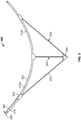
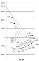
- the offset parabolic curve 500 is divided into six segments by a set of seven equi-spaced points 501-507 lying on the surface of the offset parabolic curve from its center to its outer edge.
- Six straight lines 510 connect these seven points, and six orthogonal lines 520 are erected perpendicular to these connecting lines.
- the intersection point 530 of the first two orthogonal lines determines the center of the first approximating circle.
- the intersection point 540 of the second pair of orthogonal lines establishes the center of the second circle.
- the intersection point 550 of the third pair of orthogonal lines determines the center of the third circle.
- the radius of the first approximating circle is the distance from point 530 to any of the points 501, 502, or 503, which distances are equal by construction.
- a rolling machine that can dynamically vary the spacing of the rollers (e.g., dynamically vary the spacing continuously or continually) as a function of position as the tube is moved through the rollers in accordance with the desired profile, circular approximations are not necessary and the tube can be rolled ideally in one continuous pass.
- the curved tubes and spacers may be fabricated from hollow tubes of 80 mm depth by 60 mm width and 4 mm thickness, giving a depth to the composite rib structure of 240 mm.
- Appropriate dimensions for the kingpost and braces may be, in this example, 80 mm by 60 mm.
- Reflective panels may be joined to the ribs to form the reflecting trough.
- these may by advantageously formed by coating the substrate (sheet metal) on one side with a highly efficient and durable film, for instance 3M® Specular Film - Protected manufactured by 3M Company, St Paul, MN, or ReflecTech®Plus Mirror Film manufactured by ReflecTech, Inc, Arvad, CO.
- a highly efficient and durable film for instance 3M® Specular Film - Protected manufactured by 3M Company, St Paul, MN, or ReflecTech®Plus Mirror Film manufactured by ReflecTech, Inc, Arvad, CO.
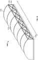
- panels for formation of the trough surface are provided. Referring to Figure 8 , for a trough of for example 12 meter length each panel 370 may have a length I of 12 m.
- flanges or bends are formed along the edges of the panels, either as the panel 370 is being unrolled or after the panel has been cut to length.
- This embodiment depicts a flange 900 formed on one edge of the panel and a z-bend 910 formed along the other edge.
- the z-bend and the flange therefore protrude on the backside of the panel, leaving the front reflective surface 810 of the panel free from obstruction.
- the outer edge of the flange is affixed to the outer edge of the z-bend in such a manner as to hold the panels securely together.
- the flange depth is preferably less than the depth of the z-bend for the two panels to mate securely.
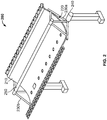
- a reflector for solar concentration may include a reflective assembly including a plurality of elongate panels forming a continuous trough and a frame configured to support the panels.
- the frame may include a plurality of spaced supports, e.g., trusses with each truss including at least one rib having a surface defining an offset parabola.
- the embodiment may include a set of precision ribs, i.e., five inner ribs and two end ribs, and six reflective panels as the major components to be assembled to form the frame.
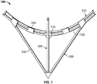
- the inner ribs may each include a single upper tube disposed on a kingpost and two braces.
- the end rib may be stronger, and may include a sandwich structure of two tubes with spacers disposed there between, and also incorporating a kingpost and two braces.
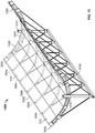
- FIG. 12 An alternate assembly technique is depicted in Figure 12 .
- the trough can be assembled upright in place using the ribs themselves to form a temporary assembly fixture 1200 (e.g., a trough assembly jig).
- the two trough end supports (not shown) are put in place, and the end ribs (see ribs 300a in Figure 13 ) are placed and secured on the rotational axles of these supports.
- the five inner ribs 300 are set in place on an alignment base 1210 (e.g., assembly jig base) that holds them upright in alignment with the two end ribs.
- the rib cross-bracing 1220 may be applied at this stage in the process.
- the panel pairs are set in place, starting with the panel pair at the center of the trough and then adding the two panel pairs to the other side.
- structural adhesive is applied to their backside where they will contact and attach to the ribs.
- some kind of weight or force is applied to the front side of the panels above the line of the ribs.
- the weighting material of course may have a compliant and smooth surface to not damage or scratch the film surface.
- the panel pair is attached to the rib as previously described.
- the bottom portions of the ribs 300a and 300b may be coupled to a stringer beam 1350, which may strengthen the structure of reflector 1300.
- a stringer beam 1350 which may strengthen the structure of reflector 1300.
- the cross-bracing 1220 is not shown in Figure 13
- the ribs 300 of reflector 1300 may be cross-braced in some embodiments (e.g., in the manner illustrated in Figure 12 ).
- the result of the rib and panel assembly is a monolithic shell gaining its strength from its depth and the depth of the ribs.
- No extensive backside space frame is required, as the panels are employed not only to reflect sunlight, but to contribute to the structural strength of the trough.
- Expensive assembly techniques like welding or extensive bolting are not necessary, and galvanized materials may be used.
- Panels do not have to pre-curved, as they take their shape from being forced and secured against the precision offset parabola of the curvature of the ribs. The accuracy of the rib upper surface is therefore the determining factor in the ultimate accuracy and thereby efficiency of the trough.
Landscapes
- Engineering & Computer Science (AREA)
- Chemical & Material Sciences (AREA)
- Life Sciences & Earth Sciences (AREA)
- Sustainable Development (AREA)
- Sustainable Energy (AREA)
- Thermal Sciences (AREA)
- Physics & Mathematics (AREA)
- Combustion & Propulsion (AREA)
- Mechanical Engineering (AREA)
- General Engineering & Computer Science (AREA)
- Optical Elements Other Than Lenses (AREA)
- Joining Of Building Structures In Genera (AREA)
- Photovoltaic Devices (AREA)
- Shaping Metal By Deep-Drawing, Or The Like (AREA)
Applications Claiming Priority (2)
| Application Number | Priority Date | Filing Date | Title |
|---|---|---|---|
| US201461992373P | 2014-05-13 | 2014-05-13 | |
| PCT/US2015/030611 WO2015175688A1 (en) | 2014-05-13 | 2015-05-13 | Low cost parabolic cylindrical trough for concentrated solar power |
Publications (2)
| Publication Number | Publication Date |
|---|---|
| EP3143347A1 EP3143347A1 (en) | 2017-03-22 |
| EP3143347B1 true EP3143347B1 (en) | 2021-10-20 |
Family
ID=53373549
Family Applications (1)
| Application Number | Title | Priority Date | Filing Date |
|---|---|---|---|
| EP15728239.3A Active EP3143347B1 (en) | 2014-05-13 | 2015-05-13 | Low cost parabolic cylindrical trough for concentrated solar power |
Country Status (6)
| Country | Link |
|---|---|
| US (1) | US10488079B2 (zh) |
| EP (1) | EP3143347B1 (zh) |
| JP (1) | JP2017519173A (zh) |
| CN (1) | CN106461270B (zh) |
| MA (1) | MA39834A (zh) |
| WO (1) | WO2015175688A1 (zh) |
Families Citing this family (3)
| Publication number | Priority date | Publication date | Assignee | Title |
|---|---|---|---|---|
| SE541607C2 (en) * | 2017-12-01 | 2019-11-12 | Absolicon Solar Collector Ab | Method and arrangement for manufacturing a parabolic trough solar collector |
| CN108031716B (zh) * | 2017-12-29 | 2023-07-18 | 绿华能源(福建)有限公司 | 一种标准化移动式轻钢生产线及其自适应送料方法 |
| EP3587955A1 (en) * | 2018-06-21 | 2020-01-01 | Rioglass Solar, S.A. | Solar concentrating system |
Citations (5)
| Publication number | Priority date | Publication date | Assignee | Title |
|---|---|---|---|---|
| US4770162A (en) * | 1983-05-26 | 1988-09-13 | Phillips Petroleum Company | Solar energy collecting system |
| DE10056077A1 (de) * | 2000-11-08 | 2002-05-29 | Deutsch Zentr Luft & Raumfahrt | Verfahren und Vorrichtung zur Bestimmung der Abbildungseigenschaften eines optischen Spiegelelementes |
| CN102298191A (zh) * | 2011-08-19 | 2011-12-28 | 中广核太阳能开发有限公司 | 一种槽式太阳能集热器的反射镜及其成型工艺 |
| WO2014020098A2 (de) * | 2012-08-02 | 2014-02-06 | Sunoyster Systems Gmbh | Tragstruktur für solarkollektoren |
| US20140076380A1 (en) * | 2012-09-14 | 2014-03-20 | Cogenra Solar, Inc. | Concentrating Solar Energy Collector |
Family Cites Families (77)
| Publication number | Priority date | Publication date | Assignee | Title |
|---|---|---|---|---|
| US290851A (en) | 1883-12-25 | Apparatus for storing and distributing solar heat | ||
| US2694357A (en) | 1950-07-18 | 1954-11-16 | Chance Vought Aircraft Inc | Boundary layer energization for flush inlets |
| US2800291A (en) | 1950-10-24 | 1957-07-23 | Stephens Arthur Veryan | Solid boundary surface for contact with a relatively moving fluid medium |
| US3892433A (en) | 1973-09-21 | 1975-07-01 | Martin Marietta Corp | Direct solar hydro-electric integrated system and concentrating heliostat for same |
| US4026112A (en) | 1975-06-20 | 1977-05-31 | Scragg Robert L | Solar reactor engine |
| US4040411A (en) | 1975-09-10 | 1977-08-09 | Rudolph Rust | Apparatus for concentration of solar radiation |
| US4034735A (en) | 1976-02-04 | 1977-07-12 | Waldrip Ralph L | Solar energy system |
| GB1599665A (en) | 1977-05-09 | 1981-10-07 | Jackson P A | Solar collector and power plant utilizing the same |
| US4202322A (en) | 1977-05-11 | 1980-05-13 | Del Manufacturing Company | Solar energy collector and heat exchanger |
| US4408595A (en) | 1978-09-05 | 1983-10-11 | Broyles Howard F | Turret mounted solar concentrator with boom mounted secondary mirror or collector |
| US4475535A (en) | 1980-03-27 | 1984-10-09 | Solmat Systems, Ltd. | Segregated solar pond |
| US4423719A (en) * | 1980-04-03 | 1984-01-03 | Solar Kinetics, Inc. | Parabolic trough solar collector |
| US4401103A (en) | 1980-04-28 | 1983-08-30 | Thompson Hugh A | Solar energy conversion apparatus |
| US4390008A (en) | 1980-06-26 | 1983-06-28 | The United Stated Of America As Represented By The Department Of Energy | Hot water tank for use with a combination of solar energy and heat-pump desuperheating |
| US4512332A (en) | 1981-04-30 | 1985-04-23 | The United States Of America As Represented By The Administrator Of The National Aeronautics And Space Administration | Stable density stratification solar pond |
| US4509501A (en) | 1982-01-13 | 1985-04-09 | Hunter Larry D | Solar energy collecting system using a primary reflector based on a pyramid structure |
| US4523629A (en) | 1982-09-30 | 1985-06-18 | The United States Of America As Represented By The United States Department Of Energy | Method and apparatus for operating an improved thermocline storage unit |
| US4675357A (en) | 1983-04-18 | 1987-06-23 | Ppg Industries, Inc. | Near infrared absorbing polymerizate |
| US4643212A (en) | 1984-03-28 | 1987-02-17 | Chicago Bridge & Iron Company | Hot liquid thermal energy storage tank and method |
| US4559926A (en) | 1984-10-03 | 1985-12-24 | Butler Barry L | Centerless-drive solar collector system |
| JPS61287157A (ja) | 1985-06-13 | 1986-12-17 | Matsushita Electric Works Ltd | 太陽電池の表面掃除装置 |
| CH668632A5 (de) | 1985-09-20 | 1989-01-13 | Erwin Mittasch | Passiver sonnenenergie-warmwasserbereiter. |
| US5058837A (en) | 1989-04-07 | 1991-10-22 | Wheeler Gary O | Low drag vortex generators |
| EP0619133B1 (de) | 1993-04-08 | 1996-11-13 | ABB Management AG | Mischkammer |
| DE4331784C2 (de) | 1993-09-18 | 1997-10-23 | Deutsche Forsch Luft Raumfahrt | Rinnenkollektor |
| US5685289A (en) | 1994-10-04 | 1997-11-11 | Yeda Research And Development Co., Ltd. | Heat storage device |
| US5598990A (en) | 1994-12-15 | 1997-02-04 | University Of Kansas Center For Research Inc. | Supersonic vortex generator |
| US5887280A (en) | 1995-03-10 | 1999-03-30 | Waring; John | Wearable article for athlete with vortex generators to reduce form drag |
| JP2000146309A (ja) * | 1998-11-04 | 2000-05-26 | Maeda Masato | 太陽熱調理器 |
| IL127323A0 (en) | 1998-11-30 | 1999-09-22 | Yeda Res & Dev | Solar energy plant |
| US6959958B2 (en) | 2000-06-09 | 2005-11-01 | Basford William C | Aerodynamic combination for improved base drag reduction |
| US7051529B2 (en) | 2002-12-20 | 2006-05-30 | United Technologies Corporation | Solar dish concentrator with a molten salt receiver incorporating thermal energy storage |
| US6907923B2 (en) | 2003-01-13 | 2005-06-21 | Carrier Corporation | Storage tank for hot water systems |
| US7191597B2 (en) | 2003-01-21 | 2007-03-20 | Los Angeles Advisory Services, Inc. | Hybrid generation with alternative fuel sources |
| US7255387B2 (en) | 2003-08-21 | 2007-08-14 | Solus Solutions And Technologies, Llc | Vortex strake device and method for reducing the aerodynamic drag of ground vehicles |
| AU2007211836A1 (en) * | 2006-02-03 | 2007-08-09 | Miralite Pty Ltd | Improved trough reflectors for solar energy collectors |
| US20070221208A1 (en) | 2006-03-07 | 2007-09-27 | Goldman Arnold J | High-temperature pipeline |
| US7690377B2 (en) | 2006-05-11 | 2010-04-06 | Brightsource Energy, Inc. | High temperature solar receiver |
| CN101501410A (zh) | 2006-06-08 | 2009-08-05 | 索波吉公司 | 用于聚集太阳能的装置和方法 |
| US8365529B2 (en) | 2006-06-30 | 2013-02-05 | United Technologies Corporation | High temperature molten salt receiver |
| US20080115817A1 (en) | 2006-11-21 | 2008-05-22 | Defries Anthony | Combined Energy Conversion |
| US7685820B2 (en) | 2006-12-08 | 2010-03-30 | United Technologies Corporation | Supercritical CO2 turbine for use in solar power plants |
| ES2345583B1 (es) | 2007-05-31 | 2011-07-28 | GAMESA INNOVATION & TECHNOLOGY, S.L. | Pala de aerogenerador con dispositivos anti-ruido. |
| EP2171367A1 (en) | 2007-06-06 | 2010-04-07 | Ausra, Inc. | Integrated solar energy receiver-storage unit |
| US8544272B2 (en) | 2007-06-11 | 2013-10-01 | Brightsource Industries (Israel) Ltd. | Solar receiver |
| EP2167380B1 (en) | 2007-06-15 | 2015-03-25 | Airbus Operations GmbH | Engine nacelle of an aircraft comprising a vortex generator arrangement |
| AU2008274136A1 (en) | 2007-07-10 | 2009-01-15 | Jose Javier Alejo Trevijano | Solar energy concentrator and assembly method |
| US7900871B2 (en) | 2007-07-20 | 2011-03-08 | Textron Innovations, Inc. | Wing leading edge having vortex generators |
| CN101105342A (zh) | 2007-08-03 | 2008-01-16 | 北京理工大学 | 汇集式聚光高温聚能储热型双回路驱动太阳能热动力装置 |
| US8062738B2 (en) | 2007-09-07 | 2011-11-22 | Samsung Electronics Co., Ltd. | Heat transfer medium and heat transfer method using the same |
| ITTO20080142A1 (it) | 2008-02-28 | 2009-08-29 | Alenia Aeronautica Spa | Presa d'aria, in particolare per un espulsore di chaff per velivolo |
| AU2009268667A1 (en) * | 2008-07-09 | 2010-01-14 | Skyfuel, Inc. | Solar collectors having slidably removable reflective panels for use in solar thermal applications |
| ITSA20080028A1 (it) | 2008-09-12 | 2008-12-12 | Green Earth S R L | Tubo collettore per concentratori solari lineari avente micropolveri ad alta temperatura come vettore. |
| US8528601B2 (en) | 2009-03-30 | 2013-09-10 | The Regents Of The University Of Michigan | Passive boundary layer control elements |
| IT1395249B1 (it) | 2009-05-19 | 2012-09-05 | Albanese | Collettore solare |
| US7961462B2 (en) | 2009-05-28 | 2011-06-14 | Alcatel Lucent | Use of vortex generators to improve efficacy of heat sinks used to cool electrical and electro-optical components |
| WO2011000522A2 (de) | 2009-06-30 | 2011-01-06 | Vladan Petrovic | Parabolrinnenkraftwerk mit speicherung der sonnenenergie und verfahren zum betreiben eines parabolrinnenkraftwerks sowie hochtemperatur-wärmespeicher |
| US20110006165A1 (en) | 2009-07-10 | 2011-01-13 | Peter Ireland | Application of conformal sub boundary layer vortex generators to a foil or aero/ hydrodynamic surface |
| DE102009033490A1 (de) * | 2009-07-15 | 2011-01-20 | Solarlite Gmbh | Segment eines Solarkollektors sowie Solarkollektoren |
| US20110067692A1 (en) | 2009-08-11 | 2011-03-24 | Sopogy, Inc. | Solid core structure parabolic trough solar energy collection system |
| DE102009039021A1 (de) | 2009-08-28 | 2011-07-21 | Flagsol GmbH, 50678 | Parabolrinnenkollektor |
| ITLE20090011A1 (it) | 2009-09-04 | 2009-12-04 | Riccardis Andrea De | Sistema di accumulo dell'energia termica da radiazione solare. |
| CN102792022B (zh) | 2009-09-18 | 2016-02-24 | 麻省理工学院 | 会聚的太阳能电力系统 |
| DE102009047945A1 (de) * | 2009-10-01 | 2011-04-07 | Mirolux Anlagenbau Gmbh | Verfahren zur Herstellung eines Formspiegels, Formspiegel und Parabolrinne für Solarkollektoren |
| FR2951252B1 (fr) | 2009-10-14 | 2011-11-25 | Centre Nat Rech Scient | Recepteur surfacique solaire modulaire texture fonctionnant a haute temperature |
| EP2524176A4 (en) * | 2010-01-15 | 2014-09-17 | Magna Marque Internat Inc | SOLAR MIRROR SET |
| US8757701B2 (en) | 2010-01-15 | 2014-06-24 | Aeroserve Technologies, Ltd. | Drag reduction device for transport vehicles having randomized irregular shaped edge vortex generating channels |
| DE102010006532A1 (de) * | 2010-02-01 | 2011-08-04 | Solarlite GmbH, 17179 | Segment eines Solarkollektors sowie Solarkollektor |
| IT1399952B1 (it) | 2010-04-29 | 2013-05-09 | Magaldi Ind Srl | Dispositivo e sistema di stoccaggio e trasporto ad alto livello di efficienza energetica |
| US8434723B2 (en) | 2010-06-01 | 2013-05-07 | Applied University Research, Inc. | Low drag asymmetric tetrahedral vortex generators |
| US8047801B2 (en) | 2010-06-23 | 2011-11-01 | General Electric Company | Wind turbine blades with aerodynamic vortex elements |
| ES2375887B1 (es) * | 2010-08-05 | 2012-10-15 | Abengoa Solar New Technologies S.A. | Estructura con vigas de sujeción de reflector primario. |
| JP5680395B2 (ja) * | 2010-12-13 | 2015-03-04 | 株式会社日立製作所 | 太陽光集光器 |
| US9039381B2 (en) | 2010-12-17 | 2015-05-26 | Vestas Wind Systems A/S | Wind turbine blade and method for manufacturing a wind turbine blade with vortex generators |
| KR20120111338A (ko) | 2011-03-31 | 2012-10-10 | 삼성전자주식회사 | 공냉식 전기장치용 먼지포집구조 및 이를 구비한 전기장치 |
| DE102011001947A1 (de) * | 2011-04-11 | 2012-10-11 | Thyssenkrupp Steel Europe Ag | Verfahren zur Herstellung eines mit Stützträgern versehenen gewölbten Reflektors |
| US20130047978A1 (en) | 2011-08-31 | 2013-02-28 | Massachusetts Institute Of Technology | Vortex-induced cleaning of surfaces |
-
2015
- 2015-05-13 MA MA039834A patent/MA39834A/fr unknown
- 2015-05-13 EP EP15728239.3A patent/EP3143347B1/en active Active
- 2015-05-13 JP JP2016567634A patent/JP2017519173A/ja not_active Ceased
- 2015-05-13 CN CN201580031280.5A patent/CN106461270B/zh not_active Expired - Fee Related
- 2015-05-13 US US15/310,536 patent/US10488079B2/en not_active Expired - Fee Related
- 2015-05-13 WO PCT/US2015/030611 patent/WO2015175688A1/en active Application Filing
Patent Citations (5)
| Publication number | Priority date | Publication date | Assignee | Title |
|---|---|---|---|---|
| US4770162A (en) * | 1983-05-26 | 1988-09-13 | Phillips Petroleum Company | Solar energy collecting system |
| DE10056077A1 (de) * | 2000-11-08 | 2002-05-29 | Deutsch Zentr Luft & Raumfahrt | Verfahren und Vorrichtung zur Bestimmung der Abbildungseigenschaften eines optischen Spiegelelementes |
| CN102298191A (zh) * | 2011-08-19 | 2011-12-28 | 中广核太阳能开发有限公司 | 一种槽式太阳能集热器的反射镜及其成型工艺 |
| WO2014020098A2 (de) * | 2012-08-02 | 2014-02-06 | Sunoyster Systems Gmbh | Tragstruktur für solarkollektoren |
| US20140076380A1 (en) * | 2012-09-14 | 2014-03-20 | Cogenra Solar, Inc. | Concentrating Solar Energy Collector |
Non-Patent Citations (1)
| Title |
|---|
| DATABASE WPI Section PQ Week 201209, Derwent World Patents Index; Class Q74, AN 2012-A71482 * |
Also Published As
| Publication number | Publication date |
|---|---|
| US20170082322A1 (en) | 2017-03-23 |
| CN106461270A (zh) | 2017-02-22 |
| WO2015175688A1 (en) | 2015-11-19 |
| JP2017519173A (ja) | 2017-07-13 |
| CN106461270B (zh) | 2019-07-26 |
| EP3143347A1 (en) | 2017-03-22 |
| MA39834A (fr) | 2015-11-19 |
| US10488079B2 (en) | 2019-11-26 |
Similar Documents
| Publication | Publication Date | Title |
|---|---|---|
| EP2315981B1 (en) | Improvements to solar thermal collectors | |
| US9425731B2 (en) | Solar panel rack | |
| US20140117190A1 (en) | Support Frame Assembly And Method Of Forming A Support Frame Assembly | |
| US20010036024A1 (en) | Matrix solar dish | |
| EP2221558A1 (en) | Beam, method for securing mirror-supporting arms to the beam, frame and method for producing the beam forming part of a cylindrical parabolic solar collector | |
| EP3143347B1 (en) | Low cost parabolic cylindrical trough for concentrated solar power | |
| US9249993B2 (en) | Support system and method for trough-shaped solar energy concentrations | |
| JP2017519173A5 (zh) | ||
| AU2011349053B2 (en) | Heliostat construction | |
| WO2018002790A1 (en) | Structure for supporting reflective panels for concentration solar collectors | |
| US20220057112A1 (en) | A heliostat sub-assembly | |
| US20240102699A1 (en) | Solar concentrator facet, solar concentrator comprising said facet and method of installation thereof |
Legal Events
| Date | Code | Title | Description |
|---|---|---|---|
| STAA | Information on the status of an ep patent application or granted ep patent |
Free format text: STATUS: THE INTERNATIONAL PUBLICATION HAS BEEN MADE |
|
| PUAI | Public reference made under article 153(3) epc to a published international application that has entered the european phase |
Free format text: ORIGINAL CODE: 0009012 |
|
| STAA | Information on the status of an ep patent application or granted ep patent |
Free format text: STATUS: REQUEST FOR EXAMINATION WAS MADE |
|
| 17P | Request for examination filed |
Effective date: 20161103 |
|
| AK | Designated contracting states |
Kind code of ref document: A1 Designated state(s): AL AT BE BG CH CY CZ DE DK EE ES FI FR GB GR HR HU IE IS IT LI LT LU LV MC MK MT NL NO PL PT RO RS SE SI SK SM TR |
|
| AX | Request for extension of the european patent |
Extension state: BA ME |
|
| STAA | Information on the status of an ep patent application or granted ep patent |
Free format text: STATUS: EXAMINATION IS IN PROGRESS |
|
| 17Q | First examination report despatched |
Effective date: 20190107 |
|
| STAA | Information on the status of an ep patent application or granted ep patent |
Free format text: STATUS: EXAMINATION IS IN PROGRESS |
|
| REG | Reference to a national code |
Ref country code: DE Ref legal event code: R079 Ref document number: 602015074248 Country of ref document: DE Free format text: PREVIOUS MAIN CLASS: F24J0002140000 Ipc: B21B0017000000 |
|
| RIC1 | Information provided on ipc code assigned before grant |
Ipc: F24S 25/13 20180101ALI20210402BHEP Ipc: F24S 23/74 20180101ALI20210402BHEP Ipc: B21B 17/00 20060101AFI20210402BHEP |
|
| GRAP | Despatch of communication of intention to grant a patent |
Free format text: ORIGINAL CODE: EPIDOSNIGR1 |
|
| STAA | Information on the status of an ep patent application or granted ep patent |
Free format text: STATUS: GRANT OF PATENT IS INTENDED |
|
| INTG | Intention to grant announced |
Effective date: 20210514 |
|
| GRAS | Grant fee paid |
Free format text: ORIGINAL CODE: EPIDOSNIGR3 |
|
| GRAA | (expected) grant |
Free format text: ORIGINAL CODE: 0009210 |
|
| STAA | Information on the status of an ep patent application or granted ep patent |
Free format text: STATUS: THE PATENT HAS BEEN GRANTED |
|
| AK | Designated contracting states |
Kind code of ref document: B1 Designated state(s): AL AT BE BG CH CY CZ DE DK EE ES FI FR GB GR HR HU IE IS IT LI LT LU LV MC MK MT NL NO PL PT RO RS SE SI SK SM TR |
|
| REG | Reference to a national code |
Ref country code: GB Ref legal event code: FG4D |
|
| REG | Reference to a national code |
Ref country code: CH Ref legal event code: EP |
|
| REG | Reference to a national code |
Ref country code: DE Ref legal event code: R096 Ref document number: 602015074248 Country of ref document: DE |
|
| REG | Reference to a national code |
Ref country code: IE Ref legal event code: FG4D |
|
| REG | Reference to a national code |
Ref country code: AT Ref legal event code: REF Ref document number: 1439487 Country of ref document: AT Kind code of ref document: T Effective date: 20211115 |
|
| REG | Reference to a national code |
Ref country code: LT Ref legal event code: MG9D |
|
| REG | Reference to a national code |
Ref country code: NL Ref legal event code: MP Effective date: 20211020 |
|
| REG | Reference to a national code |
Ref country code: AT Ref legal event code: MK05 Ref document number: 1439487 Country of ref document: AT Kind code of ref document: T Effective date: 20211020 |
|
| PG25 | Lapsed in a contracting state [announced via postgrant information from national office to epo] |
Ref country code: RS Free format text: LAPSE BECAUSE OF FAILURE TO SUBMIT A TRANSLATION OF THE DESCRIPTION OR TO PAY THE FEE WITHIN THE PRESCRIBED TIME-LIMIT Effective date: 20211020 Ref country code: LT Free format text: LAPSE BECAUSE OF FAILURE TO SUBMIT A TRANSLATION OF THE DESCRIPTION OR TO PAY THE FEE WITHIN THE PRESCRIBED TIME-LIMIT Effective date: 20211020 Ref country code: FI Free format text: LAPSE BECAUSE OF FAILURE TO SUBMIT A TRANSLATION OF THE DESCRIPTION OR TO PAY THE FEE WITHIN THE PRESCRIBED TIME-LIMIT Effective date: 20211020 Ref country code: BG Free format text: LAPSE BECAUSE OF FAILURE TO SUBMIT A TRANSLATION OF THE DESCRIPTION OR TO PAY THE FEE WITHIN THE PRESCRIBED TIME-LIMIT Effective date: 20220120 Ref country code: AT Free format text: LAPSE BECAUSE OF FAILURE TO SUBMIT A TRANSLATION OF THE DESCRIPTION OR TO PAY THE FEE WITHIN THE PRESCRIBED TIME-LIMIT Effective date: 20211020 |
|
| PG25 | Lapsed in a contracting state [announced via postgrant information from national office to epo] |
Ref country code: IS Free format text: LAPSE BECAUSE OF FAILURE TO SUBMIT A TRANSLATION OF THE DESCRIPTION OR TO PAY THE FEE WITHIN THE PRESCRIBED TIME-LIMIT Effective date: 20220220 Ref country code: SE Free format text: LAPSE BECAUSE OF FAILURE TO SUBMIT A TRANSLATION OF THE DESCRIPTION OR TO PAY THE FEE WITHIN THE PRESCRIBED TIME-LIMIT Effective date: 20211020 Ref country code: PT Free format text: LAPSE BECAUSE OF FAILURE TO SUBMIT A TRANSLATION OF THE DESCRIPTION OR TO PAY THE FEE WITHIN THE PRESCRIBED TIME-LIMIT Effective date: 20220221 Ref country code: PL Free format text: LAPSE BECAUSE OF FAILURE TO SUBMIT A TRANSLATION OF THE DESCRIPTION OR TO PAY THE FEE WITHIN THE PRESCRIBED TIME-LIMIT Effective date: 20211020 Ref country code: NO Free format text: LAPSE BECAUSE OF FAILURE TO SUBMIT A TRANSLATION OF THE DESCRIPTION OR TO PAY THE FEE WITHIN THE PRESCRIBED TIME-LIMIT Effective date: 20220120 Ref country code: NL Free format text: LAPSE BECAUSE OF FAILURE TO SUBMIT A TRANSLATION OF THE DESCRIPTION OR TO PAY THE FEE WITHIN THE PRESCRIBED TIME-LIMIT Effective date: 20211020 Ref country code: LV Free format text: LAPSE BECAUSE OF FAILURE TO SUBMIT A TRANSLATION OF THE DESCRIPTION OR TO PAY THE FEE WITHIN THE PRESCRIBED TIME-LIMIT Effective date: 20211020 Ref country code: HR Free format text: LAPSE BECAUSE OF FAILURE TO SUBMIT A TRANSLATION OF THE DESCRIPTION OR TO PAY THE FEE WITHIN THE PRESCRIBED TIME-LIMIT Effective date: 20211020 Ref country code: GR Free format text: LAPSE BECAUSE OF FAILURE TO SUBMIT A TRANSLATION OF THE DESCRIPTION OR TO PAY THE FEE WITHIN THE PRESCRIBED TIME-LIMIT Effective date: 20220121 Ref country code: ES Free format text: LAPSE BECAUSE OF FAILURE TO SUBMIT A TRANSLATION OF THE DESCRIPTION OR TO PAY THE FEE WITHIN THE PRESCRIBED TIME-LIMIT Effective date: 20211020 |
|
| REG | Reference to a national code |
Ref country code: DE Ref legal event code: R097 Ref document number: 602015074248 Country of ref document: DE |
|
| PG25 | Lapsed in a contracting state [announced via postgrant information from national office to epo] |
Ref country code: SM Free format text: LAPSE BECAUSE OF FAILURE TO SUBMIT A TRANSLATION OF THE DESCRIPTION OR TO PAY THE FEE WITHIN THE PRESCRIBED TIME-LIMIT Effective date: 20211020 Ref country code: SK Free format text: LAPSE BECAUSE OF FAILURE TO SUBMIT A TRANSLATION OF THE DESCRIPTION OR TO PAY THE FEE WITHIN THE PRESCRIBED TIME-LIMIT Effective date: 20211020 Ref country code: RO Free format text: LAPSE BECAUSE OF FAILURE TO SUBMIT A TRANSLATION OF THE DESCRIPTION OR TO PAY THE FEE WITHIN THE PRESCRIBED TIME-LIMIT Effective date: 20211020 Ref country code: EE Free format text: LAPSE BECAUSE OF FAILURE TO SUBMIT A TRANSLATION OF THE DESCRIPTION OR TO PAY THE FEE WITHIN THE PRESCRIBED TIME-LIMIT Effective date: 20211020 Ref country code: DK Free format text: LAPSE BECAUSE OF FAILURE TO SUBMIT A TRANSLATION OF THE DESCRIPTION OR TO PAY THE FEE WITHIN THE PRESCRIBED TIME-LIMIT Effective date: 20211020 Ref country code: CZ Free format text: LAPSE BECAUSE OF FAILURE TO SUBMIT A TRANSLATION OF THE DESCRIPTION OR TO PAY THE FEE WITHIN THE PRESCRIBED TIME-LIMIT Effective date: 20211020 |
|
| PLBE | No opposition filed within time limit |
Free format text: ORIGINAL CODE: 0009261 |
|
| STAA | Information on the status of an ep patent application or granted ep patent |
Free format text: STATUS: NO OPPOSITION FILED WITHIN TIME LIMIT |
|
| 26N | No opposition filed |
Effective date: 20220721 |
|
| PG25 | Lapsed in a contracting state [announced via postgrant information from national office to epo] |
Ref country code: AL Free format text: LAPSE BECAUSE OF FAILURE TO SUBMIT A TRANSLATION OF THE DESCRIPTION OR TO PAY THE FEE WITHIN THE PRESCRIBED TIME-LIMIT Effective date: 20211020 |
|
| PG25 | Lapsed in a contracting state [announced via postgrant information from national office to epo] |
Ref country code: SI Free format text: LAPSE BECAUSE OF FAILURE TO SUBMIT A TRANSLATION OF THE DESCRIPTION OR TO PAY THE FEE WITHIN THE PRESCRIBED TIME-LIMIT Effective date: 20211020 |
|
| REG | Reference to a national code |
Ref country code: DE Ref legal event code: R119 Ref document number: 602015074248 Country of ref document: DE |
|
| REG | Reference to a national code |
Ref country code: CH Ref legal event code: PL |
|
| REG | Reference to a national code |
Ref country code: BE Ref legal event code: MM Effective date: 20220531 |
|
| GBPC | Gb: european patent ceased through non-payment of renewal fee |
Effective date: 20220513 |
|
| PG25 | Lapsed in a contracting state [announced via postgrant information from national office to epo] |
Ref country code: MC Free format text: LAPSE BECAUSE OF FAILURE TO SUBMIT A TRANSLATION OF THE DESCRIPTION OR TO PAY THE FEE WITHIN THE PRESCRIBED TIME-LIMIT Effective date: 20211020 Ref country code: LU Free format text: LAPSE BECAUSE OF NON-PAYMENT OF DUE FEES Effective date: 20220513 Ref country code: LI Free format text: LAPSE BECAUSE OF NON-PAYMENT OF DUE FEES Effective date: 20220531 Ref country code: CH Free format text: LAPSE BECAUSE OF NON-PAYMENT OF DUE FEES Effective date: 20220531 |
|
| PG25 | Lapsed in a contracting state [announced via postgrant information from national office to epo] |
Ref country code: IE Free format text: LAPSE BECAUSE OF NON-PAYMENT OF DUE FEES Effective date: 20220513 Ref country code: FR Free format text: LAPSE BECAUSE OF NON-PAYMENT OF DUE FEES Effective date: 20220531 |
|
| PG25 | Lapsed in a contracting state [announced via postgrant information from national office to epo] |
Ref country code: IT Free format text: LAPSE BECAUSE OF FAILURE TO SUBMIT A TRANSLATION OF THE DESCRIPTION OR TO PAY THE FEE WITHIN THE PRESCRIBED TIME-LIMIT Effective date: 20211020 Ref country code: GB Free format text: LAPSE BECAUSE OF NON-PAYMENT OF DUE FEES Effective date: 20220513 Ref country code: DE Free format text: LAPSE BECAUSE OF NON-PAYMENT OF DUE FEES Effective date: 20221201 Ref country code: BE Free format text: LAPSE BECAUSE OF NON-PAYMENT OF DUE FEES Effective date: 20220531 |
|
| PG25 | Lapsed in a contracting state [announced via postgrant information from national office to epo] |
Ref country code: HU Free format text: LAPSE BECAUSE OF FAILURE TO SUBMIT A TRANSLATION OF THE DESCRIPTION OR TO PAY THE FEE WITHIN THE PRESCRIBED TIME-LIMIT; INVALID AB INITIO Effective date: 20150513 |
|
| PG25 | Lapsed in a contracting state [announced via postgrant information from national office to epo] |
Ref country code: MK Free format text: LAPSE BECAUSE OF FAILURE TO SUBMIT A TRANSLATION OF THE DESCRIPTION OR TO PAY THE FEE WITHIN THE PRESCRIBED TIME-LIMIT Effective date: 20211020 Ref country code: CY Free format text: LAPSE BECAUSE OF FAILURE TO SUBMIT A TRANSLATION OF THE DESCRIPTION OR TO PAY THE FEE WITHIN THE PRESCRIBED TIME-LIMIT Effective date: 20211020 |
|
| VS25 | Lapsed in a validation state [announced via postgrant information from nat. office to epo] |
Ref country code: MA Free format text: LAPSE BECAUSE OF FAILURE TO SUBMIT A TRANSLATION OF THE DESCRIPTION OR TO PAY THE FEE WITHIN THE PRESCRIBED TIME-LIMIT Effective date: 20211020 |