EP3143218B1 - Klemmteil; aus solchen klemmteilen, platten und balken zusammengebaute fussböden oder wände - Google Patents
Klemmteil; aus solchen klemmteilen, platten und balken zusammengebaute fussböden oder wände Download PDFInfo
- Publication number
- EP3143218B1 EP3143218B1 EP15733933.4A EP15733933A EP3143218B1 EP 3143218 B1 EP3143218 B1 EP 3143218B1 EP 15733933 A EP15733933 A EP 15733933A EP 3143218 B1 EP3143218 B1 EP 3143218B1
- Authority
- EP
- European Patent Office
- Prior art keywords
- clamping element
- plate
- width
- groove
- boards
- Prior art date
- Legal status (The legal status is an assumption and is not a legal conclusion. Google has not performed a legal analysis and makes no representation as to the accuracy of the status listed.)
- Active
Links
- 230000008719 thickening Effects 0.000 description 6
- 238000000034 method Methods 0.000 description 3
- 229910000831 Steel Inorganic materials 0.000 description 1
- 238000003780 insertion Methods 0.000 description 1
- 230000037431 insertion Effects 0.000 description 1
- 239000002184 metal Substances 0.000 description 1
- 230000002093 peripheral effect Effects 0.000 description 1
- 230000006641 stabilisation Effects 0.000 description 1
- 239000003381 stabilizer Substances 0.000 description 1
- 239000010959 steel Substances 0.000 description 1
Images


Classifications
-
- E—FIXED CONSTRUCTIONS
- E04—BUILDING
- E04F—FINISHING WORK ON BUILDINGS, e.g. STAIRS, FLOORS
- E04F15/00—Flooring
- E04F15/02—Flooring or floor layers composed of a number of similar elements
- E04F15/024—Sectional false floors, e.g. computer floors
- E04F15/02447—Supporting structures
- E04F15/02452—Details of junctions between the supporting structures and the panels or a panel-supporting framework
-
- E—FIXED CONSTRUCTIONS
- E04—BUILDING
- E04B—GENERAL BUILDING CONSTRUCTIONS; WALLS, e.g. PARTITIONS; ROOFS; FLOORS; CEILINGS; INSULATION OR OTHER PROTECTION OF BUILDINGS
- E04B5/00—Floors; Floor construction with regard to insulation; Connections specially adapted therefor
- E04B5/02—Load-carrying floor structures formed substantially of prefabricated units
- E04B5/10—Load-carrying floor structures formed substantially of prefabricated units with metal beams or girders, e.g. with steel lattice girders
-
- E—FIXED CONSTRUCTIONS
- E04—BUILDING
- E04F—FINISHING WORK ON BUILDINGS, e.g. STAIRS, FLOORS
- E04F15/00—Flooring
- E04F15/02—Flooring or floor layers composed of a number of similar elements
- E04F15/02177—Floor elements for use at a specific location
- E04F15/02183—Floor elements for use at a specific location for outdoor use, e.g. in decks, patios, terraces, verandas or the like
-
- E—FIXED CONSTRUCTIONS
- E04—BUILDING
- E04F—FINISHING WORK ON BUILDINGS, e.g. STAIRS, FLOORS
- E04F15/00—Flooring
- E04F15/02—Flooring or floor layers composed of a number of similar elements
- E04F15/02044—Separate elements for fastening to an underlayer
- E04F2015/0205—Separate elements for fastening to an underlayer with load-supporting elongated furring elements between the flooring elements and the underlayer
- E04F2015/02066—Separate elements for fastening to an underlayer with load-supporting elongated furring elements between the flooring elements and the underlayer with additional fastening elements between furring elements and flooring elements
- E04F2015/02077—Separate elements for fastening to an underlayer with load-supporting elongated furring elements between the flooring elements and the underlayer with additional fastening elements between furring elements and flooring elements the additional fastening elements located in-between two adjacent flooring elements
- E04F2015/02094—Engaging side grooves running along the whole length of the flooring elements
-
- E—FIXED CONSTRUCTIONS
- E04—BUILDING
- E04F—FINISHING WORK ON BUILDINGS, e.g. STAIRS, FLOORS
- E04F2201/00—Joining sheets or plates or panels
- E04F2201/05—Separate connectors or inserts, e.g. pegs, pins, keys or strips
- E04F2201/0523—Separate tongues; Interlocking keys, e.g. joining mouldings of circular, square or rectangular shape
Definitions
- the invention relates to a product for forming a floor or surface covering composed of boards.
- the invention also concerns a floor or surface covering composed of boards.
- the floor composed of floorboards comprises a number of boards, a number of wooden beams and a number of clamps.
- the beams which carry the boards are laid out parallel to each other in their longitudinal direction with regular mutual spacing.
- the boards are arranged on the beams, wherein the longitudinal direction of the boards runs substantially perpendicular to the longitudinal direction of the laid out beams.
- the boards have a groove on their narrow long sides.
- Clamps arc applied to the beams between the boards, and with a freestanding end engage in the grooves on the boards.
- the clamps are plate-like with a central screw hole and are provided with laterally positioned spring lips which hold the clamp on the beam.
- the clamps are symmetrical in form, so that a clamp engages in the groove on each of the boards between which the clamp is positioned.
- the clamp is firmly screwed between two boards when the boards and intermediate clamp are correctly positioned. In this way a firm connection is created between each board and the beams, and between the boards.
- US 2004/0045244 describes that the freestanding end on either side of the clamps is wider than the groove in the board, and should be formed relative to the groove in the board such that a minimum spacing is created the boards, in order to ensure that after positioning of the boards and the intermediate clamps, it is possible to place a screw in the screw hole.
- the width between the edges of the freestanding ends of the clamp minus twice the groove depth is thus at least equal to the diameter of the screw head.
- a secondary disadvantage is that repair is only possible by fitting a new screw into the beam if there is sufficient space.
- the invention proposes a product for forming a floor composed of boards from a plurality of boards which are provided with a groove in their side faces running in the longitudinal direction, comprising at least: a plurality of beams, and a plurality of clamping elements, wherein the clamping element is configured to cooperate with one of the beams and one or more of the boards, and comprises a substantially rectangular plate-like part with a plate width and a plate length, and provided with a central opening for receiving a screw which is provided with a screw head, wherein the plate-like part on a surface thereof is provided with a bar-like edge element which is perpendicular to the plate-like element and has a constant width up to an end face thereof which is smaller than the plate width, and extends on the surface over substantially the length of the plate-like part, wherein the central opening extends through the edge element, and the width of the edge element is at least equal to the dimension of the central opening in the width direction, and wherein a connecting structure of the beam comprises a guiding groove which
- edge element By attaching the edge element to the one surface with a width of the edge element at least equal to the dimension of the central opening in the width direction, a stop element is provided against which boards can lie against the clamp element.
- the spacing between boards adjacent to each other in their longitudinal direction is thus determined by the width of the edge element. Because the edge element has at least a width which is equal to the dimension of the central opening, the width of the edge element will be approximately equal to the diameter of the screw which can be inserted through the central opening, wherein the screw head will have a larger diameter than the width of the edge element.
- the beam with this connecting structure has the advantage that the clamping element can be placed on the beam in a position which is fixed by the protrusions which are provided with thickening at their ends, without it being necessary to tighten the screw until a clamping is achieved on the groove edge. Because the screw is not yet tightened, the clamping element can still be moved over the beam in the direction of the groove, so the clamping element is freely moveable against an edge of a board. Also the height of the clamping element may still be adjusted as long as the screw is not tightened.
- the height of the edge element from the plate-like part is less than the height of the groove from an underside of the board, allows boards of different groove height to be clamped with the clamping element, provided that the groove height is at least equal to or greater than the height of the edge element.
- the clamping element is universal, i.e. the clamping element can be used with boards with arbitrary height of the groove from the underside of the board. Because the height of the edge element from the plate-like part is smaller than the height of the groove from the underside of the board, when the screw is tightened the clamping element is pulled in the direction of the beam and the board is clamped onto a top surface of the beam to which the screw is connected via the nut.
- the invention also concerns an assembled floor or wall constructed from a product as described above, wherein in their longitudinal direction, the beams are laid out in a first direction with a mutual space between adjacent beams; the boards are laid out on the plurality of beams with the longitudinal direction of the boards in a second direction which is substantially perpendicular to the first direction, wherein a clamping element is situated on at least one of the beams between every two adjacent boards, with the protrusions of the clamping element clamping against the opposing side faces of the beam; each of the adjacent boards is placed with its side face against the edge element of the clamping element; the clamping element is connected to boards placed on opposite sides of the clamping element in that the freestanding part of the plate-like part facing the board is received in the groove of the respective board, and wherein the depth of the groove or groove part is greater than or at least equal to the free width of the freestanding part of the plate-like part of the clamping element, wherein the head of the screw lies inside the groove, and wherein the clamping element in the groove of the
- the floor or wall thus defined is a surface covering which, without being limited, comprises both a floor, a terrace floor and a wall covering.
- Figure 1 shows a perspective view of a clamping element according to an embodiment of the invention.
- the clamping element 1 according to an embodiment of the invention comprises a rectangular oblong plate 10 with width B and length L.
- the plate 10 On the widths B, the plate 10 is provided with a bar-like or oblong protrusion 12 which extends perpendicularly to one side of the plate 10.
- the protrusion 12 serves as a protrusion for stabilisation on a beam, as will be explained below.
- a central opening 14 is provided for receiving a screw 50.
- the central opening may be provided with a recess such that a head of a screw 50 held in the central opening lies below the top surface 11 of the plate 10. If the plate consists of a thin metal (for example a thin steel), such a recess is usually unnecessary.
- Figure 2 shows a side view of the clamping element in the longitudinal direction of the plate 10.
- the top surface 11 of the plate is provided with a chamfer 26 along the plate periphery. This chamfer facilitates insertion of the clamping element in a groove of a board (not shown).
- the plate In the width direction B, the plate has freestanding ends 28 which extend outside the width of the protrusions 12 over a free width C.
- Figure 3 shows a side view of the clamping element of Figure 1 in a width direction.
- the clamping element 1 On the bottom surface 16 opposite the top surface 11 of the plate, the clamping element 1 comprises an edge element or ridge 18 which extends between the two protrusions 12.
- the edge element 18 has a height 20 which is less than the length 22 of the protrusions 12, so that the protrusions extend past the free end 24 of the edge element.
- the edge element has the function of a stop when the clamping element is placed between two boards which are provided with a groove in the narrow side face in the longitudinal direction. Each freestanding end 28 of the clamping element engages in the groove of the board. When the depth of the groove is at least equal to the free width C of the freestanding end 28, in the correctly inserted position of the clamping element, the side face of the board will lie against the edge element 18. This will be shown more clearly in Figure 4 .
- the protrusions 12 may be provided with a thickening 13 at their ends on the mutually facing sides.
- the thickening 13 is such that the space between the thickenings of opposing protrusions on the clamping element is smaller than the space between the thinner parts of the protrusions 12.
- the protrusion serves as a clamping stabiliser on a beam when the clamping element is placed on the beam.
- the clamping element can thus still be moved over the length of the beam so that the clamping element is still freely moveable against an edge of a board.
- the height of the clamping element may still be set by the clamping protrusions as long as the screw is not tightened.
- the invention is restricted to the embodiment with these protrusions 12.
- the protrusions 12 may be omitted so that the plate may be provided with the bar-like edge element 18, which extends over substantially the length of the plate 10, along the long centre line on one surface of the plate.
- Figure 4 shows a side view of the underside of the clamping element.
- the edge element 18 which extends along the plate 10 has a width 30 which is substantially equal to the diameter of the central opening 14. This ensures that the space between two boards is substantially equal to the diameter of the screw. Because the screw head is held in the groove of the board (and optionally in the recess of the centre opening 14 in the plate 10 of the clamping element 1), the space between the boards is thus not determined by the size of the screw head but exclusively by the width of the edge element or part of the screw carrying the thread, when the width of the edge element is virtually equal to the screw diameter.
- the edge element 18 is provided with a thickening 28 at the site of the central opening so that the wall 32 of the edge element is thin relative to the width 30 of the edge element at the site of the central opening 14.
- this thin wall is not essential and may be omitted by choosing the width 30 of the edge element equal to the diameter of the central opening (or its dimension in the width direction of the edge element 18).
- the thickness of the wall of the edge element at the site 28 of the central opening is less than 5% of the width 30 of the edge element.
- the clamping element may be provided with a screw with a thread diameter of 5 mm.
- the thin wall then has a thickness of less than 0.25 mm The space between two boards still remains sufficient for the tip of a screwdriver when the screw between two boards is to be tightened.
- Figure 5 shows a perspective view of a beam 100 on which a clamping element 1 according to an embodiment may be attached.
- the beam 100 has a box profile 102 with a width E which is selected such that it substantially corresponds to the length of the edge element, or if protrusions are used, to the space between the protrusions 12 or between the inwardly directed thickenings of the protrusions 12 of the clamping element 1, whichever is the smaller.
- the beam 100 On a side 106 facing the boards, i.e. on the top side in the mounted state, the beam 100 has a connecting structure in the form of a guiding slot 108.
- This connecting structure serves to connect the beam to at least one clamping element by means of a screw 50 which is held in the central opening 14 of the clamping element, as shown for example in Figure 1, 2 or 3 .
- An oblong nut 52 is connected to the screw 50 and may be received in the slot 108.
- the position of the clamping element 1 will be stable when the screw is inserted in the groove, without the need for a connection between the beam 100 and the clamping element 1 by the screw 50.
- the advantage here is that an assembly of two boards with a clamping element 1 in-between may be constructed without the clamping element needing to be connected immediately to the beam. This simplifies the positioning and locating of the boards and clamping elements.
- the width F of the groove is greater than the smallest width of the oblong nut but less than a diagonal of the oblong nut, or a diagonal dimension of the nut is greater than the width F of the groove.
- connection between clamping element 1 and the beam 100 described above, by means of a slot 108 and oblong nut 52, in the use of a clamping element as described above, has the advantage that in contrast to the use of a wooden beam, the clamping element can be placed stably on the beam provided with the groove as described above and in addition can easily be moved without a connection needing to be created between the clamping element and the groove.
- This connection method also has the advantage of bridging the height of the groove in the board relative to the side 106 on which the board rests due to the screw connection, whereby the clamping element 1 is "universal" i.e. can be used for different groove heights.
- Figure 6 shows a cross section of the beam 100 in Figure 5 .
- Figures 7 to 9 show details of a floor assembled from boards, which is constructed using the clamping element 1 and the beam 100 as described above. Without being limited to this, such an assembled floor may be used as a floor inside a building but also as a terrace floor or a wall covering.
- the floor composed of boards comprises a plurality of beams 100, a plurality of clamping elements 1 and a plurality of boards 200.
- Embodiments of the beam 100 and clamping element 1 have been described above with reference to Figures 5 and 6 and Figures 1 to 4 respectively.
- the plurality of beams 100 is laid out in the longitudinal direction in a first direction R1. Adjacent beams are placed with a mutual space. A side 106 of each beam on which the boards are to be placed is directed upwards.
- the plurality of boards 200 are laid out on the upwardly directed side of the beams 100.
- the longitudinal direction of the boards runs in a second direction R2 which is substantially perpendicular to the first direction in which the beams extend longitudinally.
- FIG. 7 shows a perspective partial view of part of an assembly according to an embodiment of the invention.
- Clamping elements 1 are placed on a beam 100, wherein a screw 50 is received in the recess of the central opening 14 in the clamping element 1.
- the screw 50 is connected by means of an oblong nut 52 to the guiding slot 108 of the beam 100.
- the freestanding end 28 of the clamping element 1 is received in the groove 202 in the board 200.
- the groove 202 is arranged in the narrow long sides of the board 200 in the second direction R2.
- the groove may be continuous over the length of the board but may also be arranged as groove parts at predefined points along the length with groove-free spaces in-between.
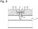
- the boards 200 each lie with their long side against the edge element 18 of a clamping element 1. Because the edge element 18 has almost the same width as the diameter of the screw 50, and the groove 202 of the board is deeper than the free width C of the freestanding end 28 of the clamping element, a space D always remains between the boards 200 between which a clamping element 1 is placed, which space is approximately equal to the width of the edge element or the diameter of the screw, while the head of the screw, which has a larger diameter than the width of the edge element, lies partly in the grooves of two adjacent boards. In the embodiment in which the head of the screw 50 is held in the clamping element 1 and optionally in the recess of the clamping element 1, the positioning of the boards 200 and clamping element 1 is not hindered in this method. Secondly, if the groove is sufficiently high in the board, with a thin plate-like part 10 without recess therein, the screw head may also be held partly inside the board.
- the boards 200 are provided with a profile 204 on the surface.
- Figure 8 shows a detailed view of a cross section of an assembly at the site of a clamping element according to an embodiment of the invention.
- the clamping element 1 is placed on the beam 100 with the protrusions 12 on either side clamped against the beam.
- the screw 50 is received in the central opening of the clamping element 1, wherein the nut on the screw is in the slot 108 of the beam.
- the freestanding end of the clamping element is held in the groove 202 of the board 20 so that the board is clamped against the top side 106 of the beam.
- Figure 9 shows a detailed view of a cross section of a clamping element between two boards according to one embodiment of the invention.
Landscapes
- Engineering & Computer Science (AREA)
- Architecture (AREA)
- Civil Engineering (AREA)
- Structural Engineering (AREA)
- General Engineering & Computer Science (AREA)
- Physics & Mathematics (AREA)
- Electromagnetism (AREA)
- Connection Of Plates (AREA)
Claims (13)
- Klemmelement zur Verwendung in einem Produkt zum Ausbilden eines Bodens oder einer Wand, die aus Brettern aus einer Vielzahl von Brettern zusammengesetzt ist, oder in einem zusammengebauten Boden oder einer zusammengebauten Wand, der/die aus dem Produkt konstruiert ist, wobei das Klemmelement umfasst:ein im Wesentlichen rechteckiges plattenförmiges Teil (10) mit einer Plattenbreite (B) und einer Plattenlänge (L), das mit einer zentralen Öffnung (14) zur Aufnahme einer mit einem Schraubenkopf versehenen Schraube versehen ist, wobeidas plattenartige Teil (10) auf einer Oberfläche desselben mit einem stabartigen Randelement (18) versehen ist, das senkrecht zu dem plattenartigen Teil verläuft und eine konstante Breite (R) bis zu einer Endfläche desselben aufweist, die kleiner als die Plattenbreite (B) ist, und sich auf der Oberfläche im Wesentlichen über die Länge des plattenartigen Teils erstreckt,wobei das Klemmelement an jeder der Kopfseiten in Plattenlängsrichtung mit einem stabförmigen Vorsprung (12) senkrecht zum plattenförmigen Teil zu einer ersten Seite des plattenförmigen Teils versehen ist,wobei jeder Vorsprung in der Mitte einer der jeweiligen Kopfseiten liegt,wobei sich das Randelement (18) zwischen den Vorsprüngen (12) auf der ersten Seite erstreckt;wobei das Randelement eine Höhe aufweist, die geringer ist als die Länge der Vorsprünge, so dass sich die Vorsprünge über ein freies Ende des Randelements hinaus erstrecken,
dadurch gekennzeichnet, dass:- die zentrale Öffnung (14) sich durch das Randelement (18) erstreckt,- die Breite (R) des Randelements (18) mindestens gleich der Abmessung der zentralen Öffnung (14) in Richtung der Breite (B) ist,- jeder Vorsprung (12) eine Breite aufweist, die kleiner ist als die Plattenbreite, und dass- die Breite des Randelements (18) im Wesentlichen gleich der Breite des Vorsprungs (12) ist. - Produkt mit einer Vielzahl von Klemmelementen (1) nach Anspruch 1,
zum Bilden eines Bodens oder einer Wand aus Brettern aus einer Vielzahl von Brettern, die jeweils mit einer in Längsrichtung verlaufenden Nut (202) in ihren Seitenflächen versehen sind, wobei das Produkt ferner mindestens umfasst:eine Vielzahl von Trägern (100),wobei das Klemmelement (1) so konfiguriert ist, dass es mit einem der Träger und einem oder mehreren der Bretter zusammenwirkt,wobei eine Verbindungsstruktur (108) des Trägers eine Führungsnut aufweist, die zur Aufnahme einer mit der Schraube (50) des Klemmelementes verbundenen Mutter (52) geeignet ist und eine größere diagonale Abmessung als eine Breite der Nut aufweist, undwobei ein freistehender Teil (28) in der Breitenrichtung des plattenförmigen Teils (10) des Klemmelementes (1) in der Nut (202) aufgenommen ist, undwobei die Höhe (K) des Randelements von dem plattenartigen Teil kleiner ist als die Höhe der Nut von einer Unterseite der Platte. - Produkt nach Anspruch 2, wobei die Tiefe der Nut größer als oder mindestens gleich der freien Breite (C) des freistehenden Teils des plattenartigen Teils des Klemmelements ist.
- Produkt nach Anspruch 2 oder 3, wobei die zentrale Öffnung (14) auf einer zweiten, der ersten Seite des plattenförmigen Teils gegenüberliegenden Seite eine Aussparung (16) aufweist, deren Abmessung größer ist als die Abmessung der zentralen Öffnung, um den Schraubenkopf aufzunehmen.
- Produkt nach einem der Ansprüche 2 bis 4, wobei der Schraubenkopf innerhalb der Nut liegt und der Schraubenkopf in der zentralen Öffnung im plattenförmigen Teil (10) aufgenommen ist.
- Produkt nach Anspruch 2, wobei das Randelement (18) des Klemmelementes an der Stelle der zentralen Öffnung (14) Wandelemente (32) mit einer im Verhältnis zur Breite (R) des Randelementes geringen Wandstärke aufweist.
- Produkt nach einem der vorhergehenden Ansprüche 2 - 6, wobei der Träger ein Kastenprofil (102) mit einer Breite (E) aufweist, die im Wesentlichen einer Länge des Randelements (18) des Klemmelementes (1) entspricht, und der Träger auf einer Seite (106) davon eine Verbindungsstruktur (108) aufweist, die zum Verbinden des Trägers mit mindestens einem Klemmelement mittels der Schraube (50) dient, die in der zentralen Öffnung des Klemmelementes gehalten ist,
wobei die Verbindungsstruktur des Trägers eine Führungsnut (108) aufweist, die zur Aufnahme der mit der Schraube verbundenen Mutter (52) geeignet ist. - Produkt nach Anspruch 6, wobei die Breite (F) der Nut des Trägers kleiner ist als die Diagonale der Mutter, aber größer als eine kleinste Breite der Mutter, und wobei die Mutter eine längliche Form aufweist.
- Produkt nach einem der Ansprüche 6 bis 8, wobei der Träger eine Breite (E) aufweist, die im Wesentlichen der Länge des Randelements (18) des plattenförmigen Teils oder einem Zwischenraum zwischen den Vorsprüngen (12) des Klemmelements entspricht.
- Zusammengesetzter Boden oder Wand aus einer Vielzahl von Klemmelementen nach Anspruch 1, einem Produkt nach einem der Ansprüche 2 bis 9 und aus einer Vielzahl von Brettern (200), wobeidie Träger (100) in ihrer Längsrichtung in einer ersten Richtung (R1) mit einem gegenseitigen Abstand zwischen benachbarten Trägern angeordnet sind,die Bretter (200) auf der Vielzahl von Trägern (100) mit einer Längsrichtung der Bretter in einer zweiten Richtung (R2) ausgelegt sind, die im Wesentlichen senkrecht zu der ersten Richtung ist,wobei ein Klemmelement (1) auf mindestens einem der Träger (100) zwischen jeweils zwei benachbarten Brettern angeordnet ist, wobei die Vorsprünge des Klemmelements gegen die gegenüberliegenden Seitenflächen des Trägers klemmen;jedes der benachbarten Bretter mit seiner Seitenfläche gegen das Randelement (18) des Klemmelements (1) gelegt ist;das Klemmelement mit Brettern (200) verbunden ist, die auf gegenüberliegenden Seiten des Klemmelements angeordnet sind, indem der freistehende Teil (28) des plattenartigen Teils, der dem Brett gegenüberliegt, in der Nut (202) des jeweiligen Bretts (200) aufgenommen ist,und wobei die Tiefe der Nut oder des Nutteils größer oder zumindest gleich der freien Breite (C) des freistehenden Teils des plattenartigen Teils des Klemmelements ist,wobei der Kopf der Schraube innerhalb der Nut liegt,und wobei das Klemmelement in der Nut der jeweiligen Bretter mittels der Mutter am Ende der Schraube (50), die in der zentralen Öffnung (14) des Klemmelementes aufgenommen ist, mit der Verbindungsstruktur (108) des Trägers verbunden ist, wobei die Höhe (K) des Randelementes von dem plattenartigen Teil kleiner ist als die Höhe der Nut von einer Unterseite des Brettes.
- Zusammengesetzter Boden oder Wand nach Anspruch 10, wobei die freie Breite (C) des freistehenden Teils (28) des plattenartigen Teils gleich oder kleiner als eine Tiefe der Nut oder des Nutteils (202) in dem Brett (200) ist.
- Zusammengesetzter Boden oder Wand nach Anspruch 10, wobei die Verbindungsstruktur des Trägers eine Führungsnut (108) aufweist, die zur Aufnahme der mit der Schraube verbundenen Mutter (52) geeignet ist, wobei die Mutter (52) eine größere diagonale Abmessung als die Breite der Nut aufweist.
- Zusammengesetzter Boden oder Wand nach einem der Ansprüche 10 bis 12, wobei die distale Endfläche des Randelements des Klemmelements nicht mit der Oberseite des Trägers in Kontakt kommt.
Applications Claiming Priority (2)
| Application Number | Priority Date | Filing Date | Title |
|---|---|---|---|
| NL2012799A NL2012799B1 (nl) | 2014-05-12 | 2014-05-12 | Klem voor een uit planken samengestelde vloer, en een systeem voor het vervaardigen van een dergelijke vloer. |
| PCT/NL2015/050334 WO2015174835A1 (en) | 2014-05-12 | 2015-05-12 | Floor or wall composed of boards, and a product for producing such a floor or wall |
Publications (2)
| Publication Number | Publication Date |
|---|---|
| EP3143218A1 EP3143218A1 (de) | 2017-03-22 |
| EP3143218B1 true EP3143218B1 (de) | 2022-06-08 |
Family
ID=53502809
Family Applications (1)
| Application Number | Title | Priority Date | Filing Date |
|---|---|---|---|
| EP15733933.4A Active EP3143218B1 (de) | 2014-05-12 | 2015-05-12 | Klemmteil; aus solchen klemmteilen, platten und balken zusammengebaute fussböden oder wände |
Country Status (3)
| Country | Link |
|---|---|
| EP (1) | EP3143218B1 (de) |
| NL (1) | NL2012799B1 (de) |
| WO (1) | WO2015174835A1 (de) |
Families Citing this family (6)
| Publication number | Priority date | Publication date | Assignee | Title |
|---|---|---|---|---|
| US9850667B2 (en) | 2015-08-24 | 2017-12-26 | Valinge Innovation Ab | Panel with a fastening device |
| SE541420C2 (en) | 2016-12-16 | 2019-09-24 | Vaelinge Innovation Ab | A set of decking boards provided with a connecting system |
| WO2018169483A1 (en) | 2017-03-16 | 2018-09-20 | Välinge Innovation AB | Connecting device, support element and connecting system for boards |
| US10526796B1 (en) * | 2017-06-26 | 2020-01-07 | Crescent Equipment Company | Deck systems and related methods |
| WO2020145866A1 (en) | 2019-01-08 | 2020-07-16 | Välinge Innovation AB | A decking system provided with a connecting system and an associated connecting device |
| LU503433B1 (fr) | 2023-02-03 | 2024-08-05 | Sinrj Invest S A R L | Système d'assemblage de planches sur solives |
Citations (5)
| Publication number | Priority date | Publication date | Assignee | Title |
|---|---|---|---|---|
| US20040045244A1 (en) * | 2002-09-06 | 2004-03-11 | Robert Hafner | Decking system with clip apparatus |
| EP1600579A1 (de) * | 2004-02-27 | 2005-11-30 | Cerland S.A.S. | Befestigungssystem für Verkleidungsplatten, insbesondere Parkettplatten |
| DE202007002282U1 (de) * | 2007-02-16 | 2008-06-19 | Möller GmbH & Co. KG | Profilelemente |
| WO2010071930A1 (en) * | 2008-12-22 | 2010-07-01 | Peter Charles Campbell-Lloyd | Flooring system and components therefore including a biscuit |
| WO2015159136A1 (en) * | 2014-04-16 | 2015-10-22 | Control Y Desarrollo Empresarial, S.L. | Covering comprising cover plates clamped to profiles |
-
2014
- 2014-05-12 NL NL2012799A patent/NL2012799B1/nl active
-
2015
- 2015-05-12 WO PCT/NL2015/050334 patent/WO2015174835A1/en active Application Filing
- 2015-05-12 EP EP15733933.4A patent/EP3143218B1/de active Active
Patent Citations (5)
| Publication number | Priority date | Publication date | Assignee | Title |
|---|---|---|---|---|
| US20040045244A1 (en) * | 2002-09-06 | 2004-03-11 | Robert Hafner | Decking system with clip apparatus |
| EP1600579A1 (de) * | 2004-02-27 | 2005-11-30 | Cerland S.A.S. | Befestigungssystem für Verkleidungsplatten, insbesondere Parkettplatten |
| DE202007002282U1 (de) * | 2007-02-16 | 2008-06-19 | Möller GmbH & Co. KG | Profilelemente |
| WO2010071930A1 (en) * | 2008-12-22 | 2010-07-01 | Peter Charles Campbell-Lloyd | Flooring system and components therefore including a biscuit |
| WO2015159136A1 (en) * | 2014-04-16 | 2015-10-22 | Control Y Desarrollo Empresarial, S.L. | Covering comprising cover plates clamped to profiles |
Also Published As
| Publication number | Publication date |
|---|---|
| EP3143218A1 (de) | 2017-03-22 |
| NL2012799B1 (nl) | 2016-02-24 |
| WO2015174835A1 (en) | 2015-11-19 |
Similar Documents
| Publication | Publication Date | Title |
|---|---|---|
| EP3143218B1 (de) | Klemmteil; aus solchen klemmteilen, platten und balken zusammengebaute fussböden oder wände | |
| US6484979B1 (en) | Adjustable electrical box support | |
| US9790980B2 (en) | Fastener nut for channel framing | |
| EP2480734B1 (de) | Stabsystem | |
| US20120110944A1 (en) | Fastener for building materials | |
| CA2997626C (en) | A set comprising panels, a supporting structure and a fastening device | |
| US20160333579A1 (en) | Connector | |
| US20110123290A1 (en) | Gangable composite clip for attaching decking and method for making | |
| WO2011045992A1 (ja) | 床板固定具 | |
| US8517317B2 (en) | Shim for a clamp system | |
| US20180334816A1 (en) | Formwork part and ceiling formwork comprising such a formwork part | |
| EP1647650A2 (de) | Sockelleiste | |
| EP3680533B1 (de) | Profilabschnittselement mit gestufter seitenwand | |
| US7049511B2 (en) | Connection box stabilizer | |
| JP4654137B2 (ja) | デッキ材の固定構造 | |
| US9464433B1 (en) | Self-tightening splice | |
| WO2014162371A1 (ja) | 固定金具 | |
| JP5296321B2 (ja) | 格子固定素子 | |
| US20060196134A1 (en) | Multi-purpose framing product | |
| KR101675635B1 (ko) | 조립식 케이블트레이 | |
| DE202013007360U1 (de) | Befestigungsvorrichtung für die Rohre einer Fußbodenheizung | |
| US20100199462A1 (en) | Mounting band, mounting arrangement and tool for handling a mounting band | |
| CA2523321A1 (en) | Skirting board | |
| US7044702B2 (en) | Screw with a plurality of screwing angles and mold device for forming the same | |
| JP4289255B2 (ja) | ラック |
Legal Events
| Date | Code | Title | Description |
|---|---|---|---|
| STAA | Information on the status of an ep patent application or granted ep patent |
Free format text: STATUS: THE INTERNATIONAL PUBLICATION HAS BEEN MADE |
|
| PUAI | Public reference made under article 153(3) epc to a published international application that has entered the european phase |
Free format text: ORIGINAL CODE: 0009012 |
|
| STAA | Information on the status of an ep patent application or granted ep patent |
Free format text: STATUS: REQUEST FOR EXAMINATION WAS MADE |
|
| 17P | Request for examination filed |
Effective date: 20161209 |
|
| AK | Designated contracting states |
Kind code of ref document: A1 Designated state(s): AL AT BE BG CH CY CZ DE DK EE ES FI FR GB GR HR HU IE IS IT LI LT LU LV MC MK MT NL NO PL PT RO RS SE SI SK SM TR |
|
| AX | Request for extension of the european patent |
Extension state: BA ME |
|
| DAV | Request for validation of the european patent (deleted) | ||
| DAX | Request for extension of the european patent (deleted) | ||
| STAA | Information on the status of an ep patent application or granted ep patent |
Free format text: STATUS: EXAMINATION IS IN PROGRESS |
|
| 17Q | First examination report despatched |
Effective date: 20171025 |
|
| STAA | Information on the status of an ep patent application or granted ep patent |
Free format text: STATUS: EXAMINATION IS IN PROGRESS |
|
| STAA | Information on the status of an ep patent application or granted ep patent |
Free format text: STATUS: EXAMINATION IS IN PROGRESS |
|
| GRAP | Despatch of communication of intention to grant a patent |
Free format text: ORIGINAL CODE: EPIDOSNIGR1 |
|
| STAA | Information on the status of an ep patent application or granted ep patent |
Free format text: STATUS: GRANT OF PATENT IS INTENDED |
|
| INTG | Intention to grant announced |
Effective date: 20220105 |
|
| RIN1 | Information on inventor provided before grant (corrected) |
Inventor name: BENTVELZEN, MARTINUS ADRIANUS MARIA Inventor name: BROOS, JOHAN MARTIEN Inventor name: VAN DER AREND, FERDINANDUS PETRUS JOHANNES |
|
| GRAS | Grant fee paid |
Free format text: ORIGINAL CODE: EPIDOSNIGR3 |
|
| GRAA | (expected) grant |
Free format text: ORIGINAL CODE: 0009210 |
|
| STAA | Information on the status of an ep patent application or granted ep patent |
Free format text: STATUS: THE PATENT HAS BEEN GRANTED |
|
| AK | Designated contracting states |
Kind code of ref document: B1 Designated state(s): AL AT BE BG CH CY CZ DE DK EE ES FI FR GB GR HR HU IE IS IT LI LT LU LV MC MK MT NL NO PL PT RO RS SE SI SK SM TR |
|
| REG | Reference to a national code |
Ref country code: GB Ref legal event code: FG4D |
|
| REG | Reference to a national code |
Ref country code: AT Ref legal event code: REF Ref document number: 1497014 Country of ref document: AT Kind code of ref document: T Effective date: 20220615 Ref country code: CH Ref legal event code: EP |
|
| REG | Reference to a national code |
Ref country code: DE Ref legal event code: R096 Ref document number: 602015079347 Country of ref document: DE |
|
| REG | Reference to a national code |
Ref country code: IE Ref legal event code: FG4D |
|
| REG | Reference to a national code |
Ref country code: LT Ref legal event code: MG9D |
|
| REG | Reference to a national code |
Ref country code: NL Ref legal event code: MP Effective date: 20220608 |
|
| PG25 | Lapsed in a contracting state [announced via postgrant information from national office to epo] |
Ref country code: SE Free format text: LAPSE BECAUSE OF FAILURE TO SUBMIT A TRANSLATION OF THE DESCRIPTION OR TO PAY THE FEE WITHIN THE PRESCRIBED TIME-LIMIT Effective date: 20220608 Ref country code: NO Free format text: LAPSE BECAUSE OF FAILURE TO SUBMIT A TRANSLATION OF THE DESCRIPTION OR TO PAY THE FEE WITHIN THE PRESCRIBED TIME-LIMIT Effective date: 20220908 Ref country code: LT Free format text: LAPSE BECAUSE OF FAILURE TO SUBMIT A TRANSLATION OF THE DESCRIPTION OR TO PAY THE FEE WITHIN THE PRESCRIBED TIME-LIMIT Effective date: 20220608 Ref country code: HR Free format text: LAPSE BECAUSE OF FAILURE TO SUBMIT A TRANSLATION OF THE DESCRIPTION OR TO PAY THE FEE WITHIN THE PRESCRIBED TIME-LIMIT Effective date: 20220608 Ref country code: GR Free format text: LAPSE BECAUSE OF FAILURE TO SUBMIT A TRANSLATION OF THE DESCRIPTION OR TO PAY THE FEE WITHIN THE PRESCRIBED TIME-LIMIT Effective date: 20220909 Ref country code: FI Free format text: LAPSE BECAUSE OF FAILURE TO SUBMIT A TRANSLATION OF THE DESCRIPTION OR TO PAY THE FEE WITHIN THE PRESCRIBED TIME-LIMIT Effective date: 20220608 Ref country code: ES Free format text: LAPSE BECAUSE OF FAILURE TO SUBMIT A TRANSLATION OF THE DESCRIPTION OR TO PAY THE FEE WITHIN THE PRESCRIBED TIME-LIMIT Effective date: 20220608 Ref country code: BG Free format text: LAPSE BECAUSE OF FAILURE TO SUBMIT A TRANSLATION OF THE DESCRIPTION OR TO PAY THE FEE WITHIN THE PRESCRIBED TIME-LIMIT Effective date: 20220908 |
|
| REG | Reference to a national code |
Ref country code: AT Ref legal event code: MK05 Ref document number: 1497014 Country of ref document: AT Kind code of ref document: T Effective date: 20220608 |
|
| PG25 | Lapsed in a contracting state [announced via postgrant information from national office to epo] |
Ref country code: RS Free format text: LAPSE BECAUSE OF FAILURE TO SUBMIT A TRANSLATION OF THE DESCRIPTION OR TO PAY THE FEE WITHIN THE PRESCRIBED TIME-LIMIT Effective date: 20220608 Ref country code: LV Free format text: LAPSE BECAUSE OF FAILURE TO SUBMIT A TRANSLATION OF THE DESCRIPTION OR TO PAY THE FEE WITHIN THE PRESCRIBED TIME-LIMIT Effective date: 20220608 |
|
| PG25 | Lapsed in a contracting state [announced via postgrant information from national office to epo] |
Ref country code: NL Free format text: LAPSE BECAUSE OF FAILURE TO SUBMIT A TRANSLATION OF THE DESCRIPTION OR TO PAY THE FEE WITHIN THE PRESCRIBED TIME-LIMIT Effective date: 20220608 |
|
| PG25 | Lapsed in a contracting state [announced via postgrant information from national office to epo] |
Ref country code: SM Free format text: LAPSE BECAUSE OF FAILURE TO SUBMIT A TRANSLATION OF THE DESCRIPTION OR TO PAY THE FEE WITHIN THE PRESCRIBED TIME-LIMIT Effective date: 20220608 Ref country code: SK Free format text: LAPSE BECAUSE OF FAILURE TO SUBMIT A TRANSLATION OF THE DESCRIPTION OR TO PAY THE FEE WITHIN THE PRESCRIBED TIME-LIMIT Effective date: 20220608 Ref country code: RO Free format text: LAPSE BECAUSE OF FAILURE TO SUBMIT A TRANSLATION OF THE DESCRIPTION OR TO PAY THE FEE WITHIN THE PRESCRIBED TIME-LIMIT Effective date: 20220608 Ref country code: PT Free format text: LAPSE BECAUSE OF FAILURE TO SUBMIT A TRANSLATION OF THE DESCRIPTION OR TO PAY THE FEE WITHIN THE PRESCRIBED TIME-LIMIT Effective date: 20221010 Ref country code: EE Free format text: LAPSE BECAUSE OF FAILURE TO SUBMIT A TRANSLATION OF THE DESCRIPTION OR TO PAY THE FEE WITHIN THE PRESCRIBED TIME-LIMIT Effective date: 20220608 Ref country code: CZ Free format text: LAPSE BECAUSE OF FAILURE TO SUBMIT A TRANSLATION OF THE DESCRIPTION OR TO PAY THE FEE WITHIN THE PRESCRIBED TIME-LIMIT Effective date: 20220608 Ref country code: AT Free format text: LAPSE BECAUSE OF FAILURE TO SUBMIT A TRANSLATION OF THE DESCRIPTION OR TO PAY THE FEE WITHIN THE PRESCRIBED TIME-LIMIT Effective date: 20220608 |
|
| PG25 | Lapsed in a contracting state [announced via postgrant information from national office to epo] |
Ref country code: PL Free format text: LAPSE BECAUSE OF FAILURE TO SUBMIT A TRANSLATION OF THE DESCRIPTION OR TO PAY THE FEE WITHIN THE PRESCRIBED TIME-LIMIT Effective date: 20220608 Ref country code: IS Free format text: LAPSE BECAUSE OF FAILURE TO SUBMIT A TRANSLATION OF THE DESCRIPTION OR TO PAY THE FEE WITHIN THE PRESCRIBED TIME-LIMIT Effective date: 20221008 |
|
| REG | Reference to a national code |
Ref country code: DE Ref legal event code: R097 Ref document number: 602015079347 Country of ref document: DE |
|
| PG25 | Lapsed in a contracting state [announced via postgrant information from national office to epo] |
Ref country code: AL Free format text: LAPSE BECAUSE OF FAILURE TO SUBMIT A TRANSLATION OF THE DESCRIPTION OR TO PAY THE FEE WITHIN THE PRESCRIBED TIME-LIMIT Effective date: 20220608 |
|
| PLBE | No opposition filed within time limit |
Free format text: ORIGINAL CODE: 0009261 |
|
| STAA | Information on the status of an ep patent application or granted ep patent |
Free format text: STATUS: NO OPPOSITION FILED WITHIN TIME LIMIT |
|
| PG25 | Lapsed in a contracting state [announced via postgrant information from national office to epo] |
Ref country code: DK Free format text: LAPSE BECAUSE OF FAILURE TO SUBMIT A TRANSLATION OF THE DESCRIPTION OR TO PAY THE FEE WITHIN THE PRESCRIBED TIME-LIMIT Effective date: 20220608 |
|
| 26N | No opposition filed |
Effective date: 20230310 |
|
| PG25 | Lapsed in a contracting state [announced via postgrant information from national office to epo] |
Ref country code: SI Free format text: LAPSE BECAUSE OF FAILURE TO SUBMIT A TRANSLATION OF THE DESCRIPTION OR TO PAY THE FEE WITHIN THE PRESCRIBED TIME-LIMIT Effective date: 20220608 |
|
| REG | Reference to a national code |
Ref country code: DE Ref legal event code: R119 Ref document number: 602015079347 Country of ref document: DE |
|
| REG | Reference to a national code |
Ref country code: CH Ref legal event code: PL |
|
| PG25 | Lapsed in a contracting state [announced via postgrant information from national office to epo] |
Ref country code: MC Free format text: LAPSE BECAUSE OF FAILURE TO SUBMIT A TRANSLATION OF THE DESCRIPTION OR TO PAY THE FEE WITHIN THE PRESCRIBED TIME-LIMIT Effective date: 20220608 |
|
| GBPC | Gb: european patent ceased through non-payment of renewal fee |
Effective date: 20230512 |
|
| REG | Reference to a national code |
Ref country code: BE Ref legal event code: MM Effective date: 20230531 |
|
| PG25 | Lapsed in a contracting state [announced via postgrant information from national office to epo] |
Ref country code: MC Free format text: LAPSE BECAUSE OF FAILURE TO SUBMIT A TRANSLATION OF THE DESCRIPTION OR TO PAY THE FEE WITHIN THE PRESCRIBED TIME-LIMIT Effective date: 20220608 Ref country code: LU Free format text: LAPSE BECAUSE OF NON-PAYMENT OF DUE FEES Effective date: 20230512 Ref country code: LI Free format text: LAPSE BECAUSE OF NON-PAYMENT OF DUE FEES Effective date: 20230531 Ref country code: IT Free format text: LAPSE BECAUSE OF FAILURE TO SUBMIT A TRANSLATION OF THE DESCRIPTION OR TO PAY THE FEE WITHIN THE PRESCRIBED TIME-LIMIT Effective date: 20220608 Ref country code: CH Free format text: LAPSE BECAUSE OF NON-PAYMENT OF DUE FEES Effective date: 20230531 |
|
| REG | Reference to a national code |
Ref country code: IE Ref legal event code: MM4A |
|
| PG25 | Lapsed in a contracting state [announced via postgrant information from national office to epo] |
Ref country code: IE Free format text: LAPSE BECAUSE OF NON-PAYMENT OF DUE FEES Effective date: 20230512 |
|
| PG25 | Lapsed in a contracting state [announced via postgrant information from national office to epo] |
Ref country code: IE Free format text: LAPSE BECAUSE OF NON-PAYMENT OF DUE FEES Effective date: 20230512 Ref country code: DE Free format text: LAPSE BECAUSE OF NON-PAYMENT OF DUE FEES Effective date: 20231201 Ref country code: GB Free format text: LAPSE BECAUSE OF NON-PAYMENT OF DUE FEES Effective date: 20230512 |
|
| PG25 | Lapsed in a contracting state [announced via postgrant information from national office to epo] |
Ref country code: FR Free format text: LAPSE BECAUSE OF NON-PAYMENT OF DUE FEES Effective date: 20230531 Ref country code: BE Free format text: LAPSE BECAUSE OF NON-PAYMENT OF DUE FEES Effective date: 20230531 |