EP3142196B1 - Anschlussadapter für ein stromschieneneinspeisesystem und sein anordnungsverfahren - Google Patents
Anschlussadapter für ein stromschieneneinspeisesystem und sein anordnungsverfahren Download PDFInfo
- Publication number
- EP3142196B1 EP3142196B1 EP16187462.3A EP16187462A EP3142196B1 EP 3142196 B1 EP3142196 B1 EP 3142196B1 EP 16187462 A EP16187462 A EP 16187462A EP 3142196 B1 EP3142196 B1 EP 3142196B1
- Authority
- EP
- European Patent Office
- Prior art keywords
- connection adapter
- electrical component
- electrical
- plug
- connection
- Prior art date
- Legal status (The legal status is an assumption and is not a legal conclusion. Google has not performed a legal analysis and makes no representation as to the accuracy of the status listed.)
- Active
Links
Images





Classifications
-
- H—ELECTRICITY
- H01—ELECTRIC ELEMENTS
- H01R—ELECTRICALLY-CONDUCTIVE CONNECTIONS; STRUCTURAL ASSOCIATIONS OF A PLURALITY OF MUTUALLY-INSULATED ELECTRICAL CONNECTING ELEMENTS; COUPLING DEVICES; CURRENT COLLECTORS
- H01R25/00—Coupling parts adapted for simultaneous co-operation with two or more identical counterparts, e.g. for distributing energy to two or more circuits
- H01R25/14—Rails or bus-bars constructed so that the counterparts can be connected thereto at any point along their length
- H01R25/142—Their counterparts
-
- H—ELECTRICITY
- H01—ELECTRIC ELEMENTS
- H01R—ELECTRICALLY-CONDUCTIVE CONNECTIONS; STRUCTURAL ASSOCIATIONS OF A PLURALITY OF MUTUALLY-INSULATED ELECTRICAL CONNECTING ELEMENTS; COUPLING DEVICES; CURRENT COLLECTORS
- H01R31/00—Coupling parts supported only by co-operation with counterpart
- H01R31/06—Intermediate parts for linking two coupling parts, e.g. adapter
-
- H—ELECTRICITY
- H01—ELECTRIC ELEMENTS
- H01R—ELECTRICALLY-CONDUCTIVE CONNECTIONS; STRUCTURAL ASSOCIATIONS OF A PLURALITY OF MUTUALLY-INSULATED ELECTRICAL CONNECTING ELEMENTS; COUPLING DEVICES; CURRENT COLLECTORS
- H01R43/00—Apparatus or processes specially adapted for manufacturing, assembling, maintaining, or repairing of line connectors or current collectors or for joining electric conductors
- H01R43/26—Apparatus or processes specially adapted for manufacturing, assembling, maintaining, or repairing of line connectors or current collectors or for joining electric conductors for engaging or disengaging the two parts of a coupling device
-
- H—ELECTRICITY
- H01—ELECTRIC ELEMENTS
- H01R—ELECTRICALLY-CONDUCTIVE CONNECTIONS; STRUCTURAL ASSOCIATIONS OF A PLURALITY OF MUTUALLY-INSULATED ELECTRICAL CONNECTING ELEMENTS; COUPLING DEVICES; CURRENT COLLECTORS
- H01R9/00—Structural associations of a plurality of mutually-insulated electrical connecting elements, e.g. terminal strips or terminal blocks; Terminals or binding posts mounted upon a base or in a case; Bases therefor
- H01R9/22—Bases, e.g. strip, block, panel
- H01R9/24—Terminal blocks
- H01R9/26—Clip-on terminal blocks for side-by-side rail- or strip-mounting
- H01R9/2625—Clip-on terminal blocks for side-by-side rail- or strip-mounting with built-in electrical component
-
- H—ELECTRICITY
- H02—GENERATION; CONVERSION OR DISTRIBUTION OF ELECTRIC POWER
- H02B—BOARDS, SUBSTATIONS OR SWITCHING ARRANGEMENTS FOR THE SUPPLY OR DISTRIBUTION OF ELECTRIC POWER
- H02B1/00—Frameworks, boards, panels, desks, casings; Details of substations or switching arrangements
- H02B1/20—Bus-bar or other wiring layouts, e.g. in cubicles, in switchyards
-
- H—ELECTRICITY
- H02—GENERATION; CONVERSION OR DISTRIBUTION OF ELECTRIC POWER
- H02B—BOARDS, SUBSTATIONS OR SWITCHING ARRANGEMENTS FOR THE SUPPLY OR DISTRIBUTION OF ELECTRIC POWER
- H02B1/00—Frameworks, boards, panels, desks, casings; Details of substations or switching arrangements
- H02B1/20—Bus-bar or other wiring layouts, e.g. in cubicles, in switchyards
- H02B1/21—Bus-bar arrangements for rack-mounted devices with withdrawable units
-
- H—ELECTRICITY
- H01—ELECTRIC ELEMENTS
- H01R—ELECTRICALLY-CONDUCTIVE CONNECTIONS; STRUCTURAL ASSOCIATIONS OF A PLURALITY OF MUTUALLY-INSULATED ELECTRICAL CONNECTING ELEMENTS; COUPLING DEVICES; CURRENT COLLECTORS
- H01R13/00—Details of coupling devices of the kinds covered by groups H01R12/70 or H01R24/00 - H01R33/00
- H01R13/46—Bases; Cases
- H01R13/502—Bases; Cases composed of different pieces
- H01R13/506—Bases; Cases composed of different pieces assembled by snap action of the parts
-
- H—ELECTRICITY
- H02—GENERATION; CONVERSION OR DISTRIBUTION OF ELECTRIC POWER
- H02B—BOARDS, SUBSTATIONS OR SWITCHING ARRANGEMENTS FOR THE SUPPLY OR DISTRIBUTION OF ELECTRIC POWER
- H02B1/00—Frameworks, boards, panels, desks, casings; Details of substations or switching arrangements
- H02B1/015—Boards, panels, desks; Parts thereof or accessories therefor
- H02B1/04—Mounting thereon of switches or of other devices in general, the switch or device having, or being without, casing
- H02B1/056—Mounting on plugboards
Definitions
- connection adapter according to claim 1, which is provided for electrically connecting an electrical component to an externally guided feed and / or signal bus, and in a plug-in direction on the supply and / or signal bus can be plugged, an arrangement of an electrical component and such a connection adapter and a method for arranging the electrical component on the connection adapter.
- interconnection bus systems are often used, which ensure the electrical supply and signal distribution to the spatially distributed electrical equipment and systems.
- the electrical connections are routed outside the equipment and installations.
- Busbars are used, for example, which are arranged on mounting strips and accessible from the outside. Thereby, the tap of the electrical supply and the electrical signals is easy and anywhere on the buses possible.
- tap connection adapters are used, which are provided for mounting or installing the modular electrical components.
- Such designed as an adapter plug-in module discloses the document EP 1 289 085 A1 , The plug-in module can be plugged onto a plug-in base, on which the busbars are arranged, with a pivoting movement. To contact the busbars of the socket, the plug-in module tulip contacts. Modular electrical components can be arranged on the plug-in module.
- the modular electrical components are conventionally connected to the connection adapter by hand.
- the patent DE 698 08 836 T2 shows a rail system to which electrical devices are held by means of an adapter.
- the adapter has a slideway in which a slider is pushed back and forth.
- the device can be connected to the adapter by first sliding the slider in one direction, so that it locks in the latch Slider is suspended, and then pushed back in the opposite direction, wherein it electrically contacts a contact end of a conductor connecting it to the rail system.
- the patent DE 103 06 548 B4 discloses a circuit breaker device in which a switching upper part is slidable on a lower switching part, wherein electrical contacts of the upper switching part are inserted into electrical contacts of the Wegunterteils, which are provided for electrically contacting the busbar.
- a connection module, the output lines associated electrical contacts, is pivotally mounted on the lower switching part or upper switching part and aufschwenkbar on the upper or lower switching part.
- EP 1 351 336 B1 discloses a plug-in module in which for each pluggable on a busbar tulip contact a screw connection is provided, to which an electrical conductor can be connected, with which the respectively electrically contacted busbar with the modular electrical component is connectable.
- EP 2 296 237 A1 discloses a connection adapter according to the preamble of claim 1.
- installation space must be available above the plug-in socket.
- a manual interconnection is expensive.
- the object of the present invention is to provide a connection adapter for an externally guided feed and / or signal bus, which can be quickly and easily connected to the modular electrical components of various functions, the installation space required being as small as possible.
- connection adapter according to the independent claim 1
- an arrangement of an electrical component and a connection adapter in particular such a connection adapter, according to the dependent claim 11 and a method for arranging an electrical component to such a connection adapter according to the independent claim 12
- Advantageous embodiments can be taken from the dependent claims.
- connection adapter which is provided for electrically connecting an electrical component to an externally guided feed and / or signal bus.
- the connection adapter can be plugged into a plug-in direction on the supply and / or signal bus.
- plug contacts preferably tulip contacts, which can be plugged onto busbars of the supply and / or signal bus.
- the feed and / or signal bus preferably extends along a plane which is spanned by an extension direction and a sliding direction.
- the sliding direction is preferably arranged transversely to the extension direction.
- the plug-in direction preferably extends transversely to the feed and / or signal bus.
- connection adapter also has electrical connection plug means for electrically contacting the electrical component.
- the electrical connection plug-in means are preferably designed as plugs or as a socket.
- the embodiment as a socket, they are preferably designed as spring-loaded terminals, in particular as push-in terminals.
- the latter furthermore has at least one fixing means.
- the fixing is starting from a fixing position in an adjustment position and back adjustable.
- it is designed as a pivoting arm, which is pivotable about a pivot axis in and against a pivoting direction. In this embodiment, it is pivotable.
- connection adapter has connection plug-in means, which are aligned against a sliding direction, so that the electrical component can be pushed onto the connection plug-in means in the sliding direction.
- the fixing means is designed for fixing the electrical component against displacement against the sliding direction.
- the fixing means is adjusted when pushing the electrical component in the adjustment position.
- the fixing means does not hinder the electrical component when pushed onto the connection plug-in means.
- the electrical component is therefore only by sliding in the sliding direction, and therefore very easy to mount the connection adapter.
- the fixing agent is adjusted against a restoring force. This will automatically reset it.
- it is preferably made of an elastic material, in particular of an elastic plastic.
- it is also an embodiment with a spring-loaded fixing possible.
- the fixing means is designed as a latching hook.
- the latching hook is deflected when starting by the electrical component. Further preferably, it is, in particular in an end position of the electrical component, automatically deflected back.
- the latching mechanism formed by this pivoting arm thus allows automatic locking of the electrical component when sliding this in the sliding direction without further manipulation of the operator.
- connection adapter In order to fix the connection adapter on the supply and / or signal bus, it preferably has two latching arms which can be pivoted in opposite directions.
- the latching arms are preferably spaced from each other by a height of the feed and / or signal bus. Particularly preferably, they are interconnected by means of a deflection bar. As a result, they are simultaneously operated in opposite directions. The release of the connection adapter from the supply and / or signal bus is then particularly easy for the fitter.
- the deflection bar is manually by pressing an Entrieglers and one-handed possible.
- the Entriegler is preferably arranged above the top wall. Particularly preferably, it is pivotable about a pivot axis. Depending on the space conditions but also a lateral arrangement of the Entrieglers is preferred so that it can be actuated from the front or from one side.
- connection adapter preferably has a device receptacle.
- the device receptacle is preferably limited by an end wall and a top wall.
- the electrical connection plug means are preferably arranged on the top wall. Preferably, they are spaced from the end wall.
- the electrical component in particular parallel to the end wall, is arranged thereon.
- connection plug means preferably have a longitudinal extent against the sliding direction. As a result, they extend into the connection adapter arranged on the electrical component in this. They then fix the electrical component against loosening away from the end wall, in particular against the plugging direction.
- connection adapter In order to additionally secure the electrical component against such detachment from the end wall, it is further preferred for the connection adapter to have at least one retaining means which is provided for fixing the electrical component to the end wall.
- the electrical component with a counter-holding means in the holding means in the sliding direction can be inserted.
- the holding means fixes the electrical component against loosening against a normal direction to the end wall, in particular against the plugging direction.
- connection adapter further comprises a display means.
- the display means preferably cooperates with the Entriegler. Most preferably, it indicates the position of the Entrieglers.
- connection adapter has fastening means for fastening an extension element, which can be arranged in the sliding direction in front of the connection adapter at this.
- extension element electrical expansion components can be arranged on the electrical component arranged on the connection adapter.
- the problem is still solved with an extension element.
- the extension element preferably has correspondingly formed countermeans to the attachment means.
- at least two extension elements in an extension direction next to each other, in particular transversely to the sliding direction, can be arranged.
- connection adapter is provided for electrically connecting the electrical component to an externally guided supply and / or signal bus, and can be plugged in a plug-in direction onto the supply and / or signal bus.
- the arrangement is characterized in that the electrical component is displaceable in a sliding direction along the connection adapter, wherein it is fixed in an end position with a fixing means of the connection adapter mechanically against displacement against the sliding direction, and is electrically contacted with electrical connection plug means of the connection adapter.
- the electrical component is mechanically or simultaneously simultaneously fixed and electrically contacted. This arrangement can be mounted by the installer only by moving the electrical component in the sliding direction.
- the electrical component is thereby displaced along the end wall.
- the end wall is preferably facing the fitter.
- the object is further achieved by a method for arranging an electrical component on such a connection adapter.
- the method provides that the electrical component is displaced in a sliding direction, wherein it is pushed onto electrical connection plug means of the connection adapter until an end position is reached. In the end position, it makes electrical contact with the electrical connection plug-in means.
- the fixing pivots in the end position of an adjustment position in the fixing position.
- the fixing means engages under the electrical component in the end position, in particular with a latching edge arranged on it. As a result, it secures the electrical component against displacement against the displacement direction.
- the electrical component is preferably first applied to the connection adapter, in particular below the connection plug-in means.
- Below the connection plug means is called in the sliding direction in front of the connection plug means.
- the space required for this in the sliding direction is limited approximately to a length of the connection plug means and a length of the electrical component. As a result, the space required for the installation space is low.
- the fixing means is previously pivoted or deflected from the fixing position in the adjustment position when applying the electrical component to the connection adapter, in particular to the end wall of the connection adapter, and / or during displacement of the electrical component in the sliding direction along the connection adapter.
- the fixing means is pivoted against a restoring force from the fixing position to the adjustment position or directed back. As a result, it is automatically swung back when reaching the end position. In this embodiment, the handling of the fixing requires no additional steps and the fixing does not hinder the pushing of the electrical component to the connection adapter.
- a feed and / or signal bus 4 has at least two feed lines 44. In the in Fig. 1 illustrated embodiment, it has three feed lines 44 and no signal lines (not shown). This is therefore a pure feed bus 4.
- the invention is not limited to such a pure feed bus 4, but also relates to feed buses 4 with more than three feed lines 44, in particular with five feed lines 44 for alternating current (L1, L2, L3, N, PE), as well as on feed and / or signal buses 4 with one or more additional signal lines.
- the feed and / or signal bus 4 includes one or more mounting ledges 41 extending along a plane (not shown).
- the mounting rails 41 are, for example, to a wall 7 (s. Fig. 2 (c) ) mountable. They are also on busbars 3, for example, on hat-shaped busbars 3, fastened.
- the plane is spanned by an extension direction 93 and a sliding direction 92.
- busbars 44 are arranged as feed lines, which extend in a straight line in the extension direction 93.
- feeder 44 and busbar are used interchangeably.
- the busbars 44 are fastened to transverse struts 46, which extend in the sliding direction 92. They are spaced apart.
- 44 longitudinal struts 45 are arranged between the busbars.
- the busbars 44 are provided for guiding a supply current.
- the mounting rails 41 may 93 different lengths (not shown) in the extension direction. They are connected by connecting strips 42 with each other.
- the connection strips 42 have electrical connection elements 421, with which the busbars 44 of different mounting strips 41 are electrically connectable. At the ends (not labeled) of the feed and / or signal bus 4 terminating elements 43 in or against the extension direction 93 on the feed and / or signal bus 4 can be pushed.
- a feed element 5 On the supply and / or signal bus 4 electrical assemblies 1, 1 ', 5, in a plug-in direction 91 can be plugged.
- a feed element 5 is shown here.
- the feed element 5 has screw terminals 51 which electrically contact the busbars 44 of the supply and / or signal bus 4 in the plugged-on state.
- supply lines (not shown) of a supply voltage network (not shown) can be connected to the screw terminals 51 a supply voltage network (not shown) can be connected.
- connection adapters 1, 1 ' are shown, to which electrical components 6 can be arranged.
- the electrical components 6 can be electrically connected to the busbars 44 by means of the connection adapters 1, 1 '.
- the connection adapter 1 are the electrical Components 6 (s. Fig. 4 ) in the sliding direction 92 pushed.
- connection adapters 1, 1 ' are each expandable with an extension element 2.
- the extension elements 2 can be pushed in the sliding direction 92 onto the respective connection adapter 1, 1 '. They are provided for receiving electrical expansion components 81, 82 which can be connected, for example, to the electrical component 6 arranged on the connection adapter 1, 1 '.
- the expansion components 81, 82 can be attached by screwing, sliding and / or by means of a busbar 3 on the extension element 2.
- connection adapter 1 The description of the following figures relates to the embodiment according to the invention of the connection adapter 1.
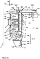
- connection adapter 1 shows the Fig. 2 (a) and (B)
- Fig. 2 (c) shows a sectional view through the connected to the feed and / or signal bus 4 connection adapter 1 of Fig. 2 (a) and (B)
- a wall 7 is shown, on which the feed and / or signal bus 4, for example, with the illustrated busbar 3, can be attached.
- connection adapter 1 can be plugged in the direction of insertion 91 on the feed and / or signal bus 4. It is provided for electrically connecting the busbars 44 with the electrical component 6 arranged on the connection adapter 1.
- connection adapter 1 allows the arrangement of various electrical components 6, which differ in their function.
- connection adapter 1 In the illustrated embodiment, exactly one electrical component 6 can be arranged on an end face 90 of the connection adapter 1, that is to say on a side of the connection adapter 1 facing the fitter.
- connection adapter 1 Embodiments of a connection adapter 1 are also preferred in which a plurality of electrical components 6, in particular in the extension direction 93 next to one another, can be arranged on the connection adapter 1.
- connection adapter 1 For electrically connecting the electrical component 6 to the busbars 44 of the supply and / or signal bus 4, the connection adapter 1 has connection plug-in means 15 which, when the electrical component 6 is arranged on the connection adapter 1, are electrically connected to the connection plug-in means 61 corresponding to the connection plug-in means 15 (see FIG. Fig. 4 ) of the electrical component 6 are connected.
- the connection plug means 15 are electrically connected in the connection adapter 1 to plug connections (not shown), for example to tulip contacts. Plug connections such as tulip contacts are well known and therefore not shown here for clarity.
- the plug-in connections can be plugged onto the busbars 44 in the insertion direction 91.
- a plug connection for each bus bar 44 is provided.
- connection plug-in means 15 of this embodiment are designed as sockets. But there are also connection adapter 1 with connector designed as a connector 15 preferred (s. Fig. 5 (a) and (B) ).
- connection plug means 15 are aligned against the sliding direction 92, so that the electrical component 6 in the sliding direction 92 on the Terminal plug means 15 can be pushed.
- the connection adapter 1 therefore enables tool-free connection of the electrical component 6 to the feed and / or signal bus 4.
- connection adapter 1 has a device receptacle 16, which is delimited by an end wall 161 and a top wall 162.
- the end wall 161 extends parallel to the mounting strip 41 when the connection adapter 1 is mounted on the feed and / or signal bus 4.
- an arrangement of the end wall 161 at an angle (not shown) greater than 0 ° to the mounting strip 41 is also preferred.
- the top wall 162 is arranged transversely to the end wall 161, and in the sliding direction 92 above, that is, behind, the end wall 161.
- the connection plug means 15 are provided on the cover wall 162. They are spaced from the end wall 161. They have a longitudinal extent 151 against the sliding direction 92.
- connection adapter 1 An electrical component 6, the mating connector means 61 are arranged when pushing the electrical component 6 on the connection adapter 1 in alignment with the connection plug means 15 is therefore pushed with their mating connector 61 in the sliding direction 92 on the connection plug means 15.
- the electrical component 6 is arranged parallel to the end wall 161 at this.
- connection adapter 1 In order to fix the electrical component 6 to the connection adapter 1, the connection adapter 1 has a fixing means 19.
- the fixing means 19 is starting from a fixing position F in an adjustment position (not shown) and back adjustable. It is designed here as a pivoting arm, which is pivotable about a pivot axis 190 in and against a pivoting direction 191.
- fixing means 19 and pivot arm are used synonymously.
- the pivot arm 19 When not arranged on the connection adapter 1 electrical component 6, the pivot arm 19 is in the fixing position F. It is designed to fix the arranged in an end position (not shown) on the connection adapter 1 electrical component 6 against displacement against the sliding direction 92. He is trained here as a latching hook.
- the terms fixing means 19, swivel arm and locking hooks are used synonymously below.
- the swivel arm 19 does not obstruct the electrical component 6 when it is arranged on the connection adapter 1, it is pivotable in the swivel direction 191 about the swivel axis 190 into the adjustment position (not shown). It is pressed in the insertion direction 91 when applying the electrical component 6 to the connection adapter 1 and / or when moving the electrical component 6 in the sliding direction 92. As a result, it is pivoted into the adjustment position.
- an actuating opening 194 is provided here, with which the pivot arm 19, for example by means of a screwdriver (not shown), can be actuated. It is pivoted to release in the adjustment position. The electrical component 6 is then detachable from the connection adapter 1 by sliding against the sliding direction 92.
- connection plug-in means 15 have a longitudinal extent 151 against the sliding direction 92, they extend into the connection adapter 1 arranged electrical component 6 in this. They thereby fix the electrical component 6 against loosening in a normal direction from the end wall 161.
- connection adapter 1 holding means 17 has.
- the electrical component 6 is pulled and fixed to the end wall 161.
- the electrical component 6 has for this purpose to the holding means 17 corresponding formed counter-holding means 62 (s. Fig. 4 ) on.
- the holding means 17 are formed here as open against the sliding direction 92 hooks.
- the electrical component 6 has as counter-holding means 62 recesses into which the holding means 17 can be inserted.
- the holding means 17 fix the electrical component 6 then also against a release in the normal direction to the end wall 161, this is here against the insertion direction 61.
- a distance 171 (s. Fig. 2 (b) ) of the holding means 17 to the end wall 161 is just dimensioned so that the connection plug means 15 and the mating plug 61 are arranged in alignment with each other when pushing the electrical component 6 on the connection adapter 1.
- guide rails 121 which extend in the sliding direction 92, are arranged on the end wall 161 and each with a mating contour 65 (s. Fig. 4 ) the electrical component 6 interact when pushed.
- the guide rails 121 and the counter-contour contours 65 are arranged so that the electrical component 6 is moved centrally of the connection adapter 1 and in alignment with the connection plug-in means 15.
- the connection adapter 1, for fixing to the feed and / or signal bus 4, furthermore has two latching arms 181, 182 (see FIG. Fig. 2 (c) ) on.
- the two latching arms 181, 182 are each about a pivot axis 71, 72 (s. Fig. 2 (c) ) in and against a pivoting direction 711, 721 (s. Fig. 2 (c) ) pivotable. They each have opposite open ends 1811, 1812, 1821, 1822 (s. Fig. 2 (c) ) on.
- a latching web 183, 184 (s. Fig. 2 (c) ) is provided, which is provided for latching engagement in recesses (not labeled) of the supply and / or signal bus 4.
- the latching arms 181, 182 are by means of a deflecting rod 13 (s. Fig. 2 (b) . (C) ) connected with each other.
- the deflecting rod 13 is in an interior 10 (s. Fig. 2 (b) . (C) ) of the connection adapter 1, between two housing parts 11, 12 (s. Fig. 2 (b) . (C) ) of the connection adapter 1 is arranged. It extends parallel to the sliding direction 92, and is in a guide groove 111 (s. Fig. 2 (b) . (C) ) guided.
- the deflecting bar 13 has two opposite open ends 131, 132 (see FIG. Fig. 2 (b) ), on each of which a head element 133, 134 (s. Fig. 2 (b) . (C) ) is arranged.
- the headers are in headmounts 112 (s. Fig. 2 (b) ), 135 (s. Fig. 2 (c) ) rot
- the first head element 133 is rotatably arranged at the second open end 1812 of the first of the two latching arms 181. Since the latching web 183 of the first latching arm 181 is arranged at the first open end 1811, that of the head element 133 is arranged opposite.
- the second header 134 is at the first open end 1821 of the second latch arm 182, and therefore his locking bar 184 adjacent rotatably mounted.
- the latching arms 181, 182 are thereby pivotally opposite each other.
- the second open end 1822 of the first latching arm 182 is formed as a manually depressible Entriegler 14. It is arranged here in the sliding direction 92 above the top wall 162 and can be actuated against the sliding direction 92.
- the second locking arm 182 is pivoted about its pivot axis 72 against its pivoting direction 721.
- its latching web 184 is released from the recess of the feed and / or signal bus 4.
- the deflecting rod 13 is raised with the second locking arm 182 approximately in the sliding direction 92. It then pulls the first locking arm 181 approximately in the sliding direction 92. As a result, it is pivoted about its pivot axis 71 against its pivoting direction 711.
- the latching web 183 of the first latching arm 181 is then also released from the recess of the feed and / or signal bus 4. This is done by a display means 114, which through a viewing window 122 (s. Fig. 2 (a) ) is visible in the second housing part 12 of the connection adapter 1, and which is attached to the second open end 1822 of the second latching arm 182 visible to the fitter.
- the display means 114 is dimensioned such that it represents the secure locking of the latching webs 183, 184 in the recesses of the feed and / or signal bus 4.
- the latching arms 181, 182 In order to ensure an automatic pivoting back of the latching arms 181, 182, it is preferred that they are pivotable against their restoring force against their pivoting direction 711, 721 only against a restoring force. As a result, the locking webs 183, 184 of the locking arms 181, 182 automatically in the to Locking provided recesses of the feed and / or signal bus 4 is pulled or pressed.
- connection adapter 1 is by means of an extension element 2, which Fig. 3 (a) shows, expandable.
- the extension element 2 is slidable in the sliding direction 92 on the connection adapter 1.
- the connection adapter 1 recordings 115 (s. Fig. 5 (a) . (B) ), in which guide rails 21 of the extension element 2 can be inserted.
- a Verraststeg 20 is arranged on the extension element 2 as a counter-fastening means.
- the Verraststeg 20 is for locking with serving as a fastener locking edge 113 (s. Fig. 2 (c) ) of the connection adapter 1 is provided. It secures the extension element 2 against displacement against the displacement direction 92, and therefore against loosening of the connection adapter 1.
- the extension element 2 is therefore without tools, only by Aufusionn, on the connection adapter 1 can be arranged.
- connection adapter 1 electrical expansion components 81, 82 of the electrical component 6 arranged on the connection adapter 1 can be arranged adjacently.
- a busbar 3 is provided, to which the expansion components 81, 82 can be fastened.
- the extension element 2 can also be designed to slide the expansion components 81, 82, for their screwing and / or another attachment.
- the extension element 2 serves to support the expansion components 81, 82, in particular during their assembly.
- the Fig. 3 (b) shows two juxtaposed, attached to each other extension elements 2.
- the extension elements 2 have for each on one side extension tabs 24.
- On the other side extension grooves 22 are provided, in which engage the extension tabs 24 of each adjacent extension element 2.
- the snap element 26 is provided on one side and a notch 25 on the other side.
- the snap element 26 engages in the notch 25 of the adjacent extension element 2.
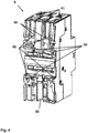
- Fig. 4 shows a can be arranged on the connection adapter 1 electrical component 6. Shown is a rear wall 60 of the electrical component 6, with which this can be arranged on the end wall 161 of the connection adapter 1.
- connection adapter 1 corresponding formed counter holding means 62, in which the holding means 17 are inserted. Furthermore, the mating connection plug-in means 61 into which the connection plug-in means 15 of the connection adapter 1 can be inserted are shown.
- connection adapter 1 engages in its fixing position F also a fixing edge 63 of the electrical component 6 shown.
- fastening means 64 for fastening the electrical component 6 to a busbar 3 are shown, with which the electrical component 6 can be fastened to conventional adapters (not shown).
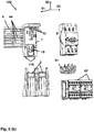
- the Fig. 5 (a) and (B) each show an arrangement 100 from the arranged on the feed and / or signal bus 4 connection adapter 1 and the electrical component 6 Fig. 4 in an explosive view.
- the Fig. 5 (a) and (B) also show electrical expansion components 81, 82, with which the arrangement is expandable, and extension elements 2, which can be arranged on the connection adapter 1, and which are provided for arranging the 81, 82 expansion components.
- the electrical component 6 is here a motor protection switch.
- a starter 82 is shown, which is electrically connected by means of an electrical connection element 81 to the motor protection switch 6.
- the connecting element 81 and the starter 82 can be arranged on the extension element 2 for this purpose.
- the arrangement of the motor protection switch 6, the starter 82 and the electrical connection element 81 can be used as a direct starter for an electric motor (not shown). It allows the operation of the electric motor in one direction of rotation.
- the extension element 2 is extended by a second extension element 2, which is arranged in the extension direction 93 next to this.
- the second starter 82 can then be arranged on the second extension element 2.
- connection adapter 1 and the extension elements 2 are also for electrical components 6 with a different function, for example for sensors, position switches, contactors, frequency converters, line filters, overvoltage protection devices or indicator lights.
Landscapes
- Engineering & Computer Science (AREA)
- Power Engineering (AREA)
- Manufacturing & Machinery (AREA)
- Details Of Connecting Devices For Male And Female Coupling (AREA)
Priority Applications (1)
| Application Number | Priority Date | Filing Date | Title |
|---|---|---|---|
| PL16187462T PL3142196T3 (pl) | 2015-09-09 | 2016-09-06 | Adapter przyłączeniowy dla układu zasilania szyny prądowej i sposób jego rozmieszczenia |
Applications Claiming Priority (1)
| Application Number | Priority Date | Filing Date | Title |
|---|---|---|---|
| DE102015115197.9A DE102015115197A1 (de) | 2015-09-09 | 2015-09-09 | Anschlussadapter für ein Stromschieneneinspeisesystem |
Publications (2)
| Publication Number | Publication Date |
|---|---|
| EP3142196A1 EP3142196A1 (de) | 2017-03-15 |
| EP3142196B1 true EP3142196B1 (de) | 2018-12-12 |
Family
ID=56893775
Family Applications (1)
| Application Number | Title | Priority Date | Filing Date |
|---|---|---|---|
| EP16187462.3A Active EP3142196B1 (de) | 2015-09-09 | 2016-09-06 | Anschlussadapter für ein stromschieneneinspeisesystem und sein anordnungsverfahren |
Country Status (3)
| Country | Link |
|---|---|
| EP (1) | EP3142196B1 (pl) |
| DE (1) | DE102015115197A1 (pl) |
| PL (1) | PL3142196T3 (pl) |
Cited By (2)
| Publication number | Priority date | Publication date | Assignee | Title |
|---|---|---|---|---|
| US11108185B2 (en) | 2019-08-29 | 2021-08-31 | Rockwell Automation Switzerland Gmbh | Busbar adapter with shielded terminals |
| WO2025218857A1 (de) | 2024-04-19 | 2025-10-23 | Rittal Gmbh & Co. Kg | Anschlussadapter für ein berührungsschutzsystem mit berührungsgesichertem leiteranschluss |
Families Citing this family (1)
| Publication number | Priority date | Publication date | Assignee | Title |
|---|---|---|---|---|
| US11515691B2 (en) | 2020-09-30 | 2022-11-29 | Rockwell Automation Switzerland Gmbh | Modular low voltage power distribution module |
Family Cites Families (12)
| Publication number | Priority date | Publication date | Assignee | Title |
|---|---|---|---|---|
| FR2649550B1 (pl) * | 1989-07-06 | 1991-10-11 | Telemecanique | |
| IT1296772B1 (it) * | 1997-05-16 | 1999-07-27 | Abb Turati S P A | Adattatore per il collegamento modulare di apparecchiature elettriche ad un sistema di barre di distribuzione dell'energia elettrica |
| DE10061940C2 (de) * | 2000-12-13 | 2002-11-21 | Woehner Gmbh & Co Kg | Kupplungsplatte für Stromschienenadapter |
| DE10119457C1 (de) * | 2001-04-20 | 2002-11-21 | Siemens Ag | Verbraucherabzweig |
| DE50115560D1 (de) | 2001-09-03 | 2010-08-26 | Abb Schweiz Ag | Steckmodul für einen Niederspannungsverteiler |
| EP1351336B1 (de) | 2002-03-11 | 2011-10-19 | ABB Schweiz AG | Steckmodul für Stecksockelsystem |
| DE10306548B4 (de) * | 2003-02-17 | 2005-02-03 | Wöhner GmbH & Co. KG Elektrotechnische Systeme | Schutzschaltereinrichtung |
| DE10335496A1 (de) * | 2003-08-02 | 2005-02-24 | Abb Patent Gmbh | Auf Trägerelementen einer elektrischen Einrichtung anzuordnendes Teil |
| DE202004016746U1 (de) * | 2004-10-28 | 2005-12-01 | Siemens Ag | Sammelschienensystem für Schaltgeräte mit Modulen, die über Verbindungsstecker mit ausgesetzter Ausspeiseklemme elektrisch kontaktierbar sind |
| DE102009029434B4 (de) * | 2009-09-14 | 2011-07-07 | Wöhner GmbH & Co. KG Elektrotechnische Systeme, 96472 | Adapter zur Aufnahme elektrischer Installationsgeräte und zur Befestigung auf einem Stromschienensystem |
| DE102011001274A1 (de) * | 2011-03-15 | 2012-09-20 | Phoenix Contact Gmbh & Co. Kg | Stecksystem mit einem Hutschienenbus |
| US8715017B1 (en) * | 2012-02-08 | 2014-05-06 | Phoenix Contact Development and Manufacturing, Inc. | Terminal block having an extender body fitted to a contact body |
-
2015
- 2015-09-09 DE DE102015115197.9A patent/DE102015115197A1/de not_active Ceased
-
2016
- 2016-09-06 EP EP16187462.3A patent/EP3142196B1/de active Active
- 2016-09-06 PL PL16187462T patent/PL3142196T3/pl unknown
Non-Patent Citations (1)
| Title |
|---|
| None * |
Cited By (3)
| Publication number | Priority date | Publication date | Assignee | Title |
|---|---|---|---|---|
| US11108185B2 (en) | 2019-08-29 | 2021-08-31 | Rockwell Automation Switzerland Gmbh | Busbar adapter with shielded terminals |
| WO2025218857A1 (de) | 2024-04-19 | 2025-10-23 | Rittal Gmbh & Co. Kg | Anschlussadapter für ein berührungsschutzsystem mit berührungsgesichertem leiteranschluss |
| DE102024111074A1 (de) * | 2024-04-19 | 2025-10-23 | Rittal Gmbh & Co. Kg | Anschlussadapter für ein Berührungsschutzsystem mit berührungsgesichertem Leiteranschluss |
Also Published As
| Publication number | Publication date |
|---|---|
| PL3142196T3 (pl) | 2019-03-29 |
| DE102015115197A1 (de) | 2017-03-09 |
| EP3142196A1 (de) | 2017-03-15 |
Similar Documents
| Publication | Publication Date | Title |
|---|---|---|
| DE102012011676B4 (de) | Befestigungsklemme und Baueinheit mit zwei Befestigungsklemmen und mehreren nebeneinander angeordneten Reihenklemmen | |
| EP3066901B1 (de) | Komponentenaufbausystem | |
| DE102006003064A1 (de) | Elektrischer Reihenklemmenblock | |
| EP0847106A2 (de) | Anschluss-, Trenn- oder Schaltleiste | |
| EP3142196B1 (de) | Anschlussadapter für ein stromschieneneinspeisesystem und sein anordnungsverfahren | |
| BE1028102B1 (de) | Stromschienenadapter zur elektrischen Verbindung wenigstens eines Steckmoduls mit wenigstens einer Stromschiene | |
| WO2011054743A2 (de) | Montageanordnung für elektrische geräte | |
| DE10237701B4 (de) | Verbindungsklemme für ein-, mehrdrähtige, insbesondere feindrähtige, elektrische Leiter | |
| DE102019000410B4 (de) | Leuchte und Adapter für Leuchte | |
| EP2671286B1 (de) | Verteilerblock | |
| DE4124487A1 (de) | Adapter | |
| EP1388914B1 (de) | Anschlusssystem | |
| WO2022106262A1 (de) | Klemme für elektrische leitungen | |
| EP0621670A1 (de) | Schalter mit Hilfsstromkreisen | |
| EP2511988B1 (de) | Leitungsaufnahmevorrichtung mit Zugentlastung | |
| DE102005025932B4 (de) | Anschlusseinrichtung mit Hauptsammelschienen, einer Schutzschaltereinheit und einer Zählerfeldeinheit | |
| WO2020114557A1 (de) | Adaptergehäuse für einen kontakteinsatz zur fixierung auf einer hutschiene | |
| DE102014105725A1 (de) | Elektrisches Gerät und Leiteranschlussklemme sowie Sockelteil hierzu | |
| DE29903002U1 (de) | Isoliergehäuse zur Befestigung an einer Tragschiene | |
| EP3127190A1 (de) | Konfigurierbare elektrische steckanordnung | |
| EP2482081B1 (de) | Anschlussvorrichtung für einen Stromzähler | |
| DE4438215C2 (de) | NH-Sicherungs-Lasttrennschalter mit Sicherungsüberwachung | |
| WO2010054721A1 (de) | Halter zur befestigung einer anschlussleiste an einem trägergestell und anordnung zur erdung einer anschlussleiste | |
| DE10340212B4 (de) | Verteileranordnung | |
| WO2018001682A1 (de) | Durchführungsklemme |
Legal Events
| Date | Code | Title | Description |
|---|---|---|---|
| PUAI | Public reference made under article 153(3) epc to a published international application that has entered the european phase |
Free format text: ORIGINAL CODE: 0009012 |
|
| STAA | Information on the status of an ep patent application or granted ep patent |
Free format text: STATUS: THE APPLICATION HAS BEEN PUBLISHED |
|
| AK | Designated contracting states |
Kind code of ref document: A1 Designated state(s): AL AT BE BG CH CY CZ DE DK EE ES FI FR GB GR HR HU IE IS IT LI LT LU LV MC MK MT NL NO PL PT RO RS SE SI SK SM TR |
|
| AX | Request for extension of the european patent |
Extension state: BA ME |
|
| STAA | Information on the status of an ep patent application or granted ep patent |
Free format text: STATUS: REQUEST FOR EXAMINATION WAS MADE |
|
| 17P | Request for examination filed |
Effective date: 20170830 |
|
| RBV | Designated contracting states (corrected) |
Designated state(s): AL AT BE BG CH CY CZ DE DK EE ES FI FR GB GR HR HU IE IS IT LI LT LU LV MC MK MT NL NO PL PT RO RS SE SI SK SM TR |
|
| RIC1 | Information provided on ipc code assigned before grant |
Ipc: H01R 13/506 20060101ALN20180606BHEP Ipc: H01R 9/26 20060101ALI20180606BHEP Ipc: H01R 43/26 20060101AFI20180606BHEP Ipc: H02B 1/056 20060101ALN20180606BHEP Ipc: H01R 31/06 20060101ALI20180606BHEP Ipc: H01R 25/14 20060101ALI20180606BHEP |
|
| GRAP | Despatch of communication of intention to grant a patent |
Free format text: ORIGINAL CODE: EPIDOSNIGR1 |
|
| STAA | Information on the status of an ep patent application or granted ep patent |
Free format text: STATUS: GRANT OF PATENT IS INTENDED |
|
| RIC1 | Information provided on ipc code assigned before grant |
Ipc: H01R 9/26 20060101ALI20180611BHEP Ipc: H01R 25/14 20060101ALI20180611BHEP Ipc: H01R 13/506 20060101ALN20180611BHEP Ipc: H01R 31/06 20060101ALI20180611BHEP Ipc: H01R 43/26 20060101AFI20180611BHEP Ipc: H02B 1/056 20060101ALN20180611BHEP |
|
| INTG | Intention to grant announced |
Effective date: 20180718 |
|
| RAP1 | Party data changed (applicant data changed or rights of an application transferred) |
Owner name: EATON INTELLIGENT POWER LIMITED |
|
| GRAJ | Information related to disapproval of communication of intention to grant by the applicant or resumption of examination proceedings by the epo deleted |
Free format text: ORIGINAL CODE: EPIDOSDIGR1 |
|
| STAA | Information on the status of an ep patent application or granted ep patent |
Free format text: STATUS: REQUEST FOR EXAMINATION WAS MADE |
|
| REG | Reference to a national code |
Ref country code: DE Ref legal event code: R079 Ref document number: 502016002777 Country of ref document: DE Free format text: PREVIOUS MAIN CLASS: H01R0013506000 Ipc: H01R0043260000 |
|
| GRAS | Grant fee paid |
Free format text: ORIGINAL CODE: EPIDOSNIGR3 |
|
| STAA | Information on the status of an ep patent application or granted ep patent |
Free format text: STATUS: GRANT OF PATENT IS INTENDED |
|
| GRAP | Despatch of communication of intention to grant a patent |
Free format text: ORIGINAL CODE: EPIDOSNIGR1 |
|
| GRAA | (expected) grant |
Free format text: ORIGINAL CODE: 0009210 |
|
| STAA | Information on the status of an ep patent application or granted ep patent |
Free format text: STATUS: THE PATENT HAS BEEN GRANTED |
|
| INTC | Intention to grant announced (deleted) | ||
| RIC1 | Information provided on ipc code assigned before grant |
Ipc: H01R 9/26 20060101ALI20181009BHEP Ipc: H01R 13/506 20060101ALN20181009BHEP Ipc: H01R 25/14 20060101ALI20181009BHEP Ipc: H02B 1/056 20060101ALN20181009BHEP Ipc: H01R 31/06 20060101ALI20181009BHEP Ipc: H01R 43/26 20060101AFI20181009BHEP |
|
| INTG | Intention to grant announced |
Effective date: 20181022 |
|
| AK | Designated contracting states |
Kind code of ref document: B1 Designated state(s): AL AT BE BG CH CY CZ DE DK EE ES FI FR GB GR HR HU IE IS IT LI LT LU LV MC MK MT NL NO PL PT RO RS SE SI SK SM TR |
|
| REG | Reference to a national code |
Ref country code: GB Ref legal event code: FG4D Free format text: NOT ENGLISH |
|
| REG | Reference to a national code |
Ref country code: CH Ref legal event code: EP |
|
| REG | Reference to a national code |
Ref country code: AT Ref legal event code: REF Ref document number: 1077231 Country of ref document: AT Kind code of ref document: T Effective date: 20181215 |
|
| REG | Reference to a national code |
Ref country code: DE Ref legal event code: R096 Ref document number: 502016002777 Country of ref document: DE |
|
| REG | Reference to a national code |
Ref country code: IE Ref legal event code: FG4D Free format text: LANGUAGE OF EP DOCUMENT: GERMAN |
|
| REG | Reference to a national code |
Ref country code: NL Ref legal event code: FP |
|
| REG | Reference to a national code |
Ref country code: LT Ref legal event code: MG4D |
|
| PG25 | Lapsed in a contracting state [announced via postgrant information from national office to epo] |
Ref country code: NO Free format text: LAPSE BECAUSE OF FAILURE TO SUBMIT A TRANSLATION OF THE DESCRIPTION OR TO PAY THE FEE WITHIN THE PRESCRIBED TIME-LIMIT Effective date: 20190312 Ref country code: FI Free format text: LAPSE BECAUSE OF FAILURE TO SUBMIT A TRANSLATION OF THE DESCRIPTION OR TO PAY THE FEE WITHIN THE PRESCRIBED TIME-LIMIT Effective date: 20181212 Ref country code: BG Free format text: LAPSE BECAUSE OF FAILURE TO SUBMIT A TRANSLATION OF THE DESCRIPTION OR TO PAY THE FEE WITHIN THE PRESCRIBED TIME-LIMIT Effective date: 20190312 Ref country code: LT Free format text: LAPSE BECAUSE OF FAILURE TO SUBMIT A TRANSLATION OF THE DESCRIPTION OR TO PAY THE FEE WITHIN THE PRESCRIBED TIME-LIMIT Effective date: 20181212 Ref country code: HR Free format text: LAPSE BECAUSE OF FAILURE TO SUBMIT A TRANSLATION OF THE DESCRIPTION OR TO PAY THE FEE WITHIN THE PRESCRIBED TIME-LIMIT Effective date: 20181212 Ref country code: LV Free format text: LAPSE BECAUSE OF FAILURE TO SUBMIT A TRANSLATION OF THE DESCRIPTION OR TO PAY THE FEE WITHIN THE PRESCRIBED TIME-LIMIT Effective date: 20181212 Ref country code: ES Free format text: LAPSE BECAUSE OF FAILURE TO SUBMIT A TRANSLATION OF THE DESCRIPTION OR TO PAY THE FEE WITHIN THE PRESCRIBED TIME-LIMIT Effective date: 20181212 |
|
| PG25 | Lapsed in a contracting state [announced via postgrant information from national office to epo] |
Ref country code: AL Free format text: LAPSE BECAUSE OF FAILURE TO SUBMIT A TRANSLATION OF THE DESCRIPTION OR TO PAY THE FEE WITHIN THE PRESCRIBED TIME-LIMIT Effective date: 20181212 Ref country code: SE Free format text: LAPSE BECAUSE OF FAILURE TO SUBMIT A TRANSLATION OF THE DESCRIPTION OR TO PAY THE FEE WITHIN THE PRESCRIBED TIME-LIMIT Effective date: 20181212 Ref country code: GR Free format text: LAPSE BECAUSE OF FAILURE TO SUBMIT A TRANSLATION OF THE DESCRIPTION OR TO PAY THE FEE WITHIN THE PRESCRIBED TIME-LIMIT Effective date: 20190313 Ref country code: RS Free format text: LAPSE BECAUSE OF FAILURE TO SUBMIT A TRANSLATION OF THE DESCRIPTION OR TO PAY THE FEE WITHIN THE PRESCRIBED TIME-LIMIT Effective date: 20181212 |
|
| PG25 | Lapsed in a contracting state [announced via postgrant information from national office to epo] |
Ref country code: CZ Free format text: LAPSE BECAUSE OF FAILURE TO SUBMIT A TRANSLATION OF THE DESCRIPTION OR TO PAY THE FEE WITHIN THE PRESCRIBED TIME-LIMIT Effective date: 20181212 Ref country code: PT Free format text: LAPSE BECAUSE OF FAILURE TO SUBMIT A TRANSLATION OF THE DESCRIPTION OR TO PAY THE FEE WITHIN THE PRESCRIBED TIME-LIMIT Effective date: 20190412 |
|
| PG25 | Lapsed in a contracting state [announced via postgrant information from national office to epo] |
Ref country code: EE Free format text: LAPSE BECAUSE OF FAILURE TO SUBMIT A TRANSLATION OF THE DESCRIPTION OR TO PAY THE FEE WITHIN THE PRESCRIBED TIME-LIMIT Effective date: 20181212 Ref country code: SM Free format text: LAPSE BECAUSE OF FAILURE TO SUBMIT A TRANSLATION OF THE DESCRIPTION OR TO PAY THE FEE WITHIN THE PRESCRIBED TIME-LIMIT Effective date: 20181212 Ref country code: IS Free format text: LAPSE BECAUSE OF FAILURE TO SUBMIT A TRANSLATION OF THE DESCRIPTION OR TO PAY THE FEE WITHIN THE PRESCRIBED TIME-LIMIT Effective date: 20190412 Ref country code: RO Free format text: LAPSE BECAUSE OF FAILURE TO SUBMIT A TRANSLATION OF THE DESCRIPTION OR TO PAY THE FEE WITHIN THE PRESCRIBED TIME-LIMIT Effective date: 20181212 Ref country code: SK Free format text: LAPSE BECAUSE OF FAILURE TO SUBMIT A TRANSLATION OF THE DESCRIPTION OR TO PAY THE FEE WITHIN THE PRESCRIBED TIME-LIMIT Effective date: 20181212 |
|
| REG | Reference to a national code |
Ref country code: DE Ref legal event code: R097 Ref document number: 502016002777 Country of ref document: DE |
|
| PLBE | No opposition filed within time limit |
Free format text: ORIGINAL CODE: 0009261 |
|
| STAA | Information on the status of an ep patent application or granted ep patent |
Free format text: STATUS: NO OPPOSITION FILED WITHIN TIME LIMIT |
|
| PG25 | Lapsed in a contracting state [announced via postgrant information from national office to epo] |
Ref country code: DK Free format text: LAPSE BECAUSE OF FAILURE TO SUBMIT A TRANSLATION OF THE DESCRIPTION OR TO PAY THE FEE WITHIN THE PRESCRIBED TIME-LIMIT Effective date: 20181212 Ref country code: SI Free format text: LAPSE BECAUSE OF FAILURE TO SUBMIT A TRANSLATION OF THE DESCRIPTION OR TO PAY THE FEE WITHIN THE PRESCRIBED TIME-LIMIT Effective date: 20181212 |
|
| 26N | No opposition filed |
Effective date: 20190913 |
|
| PG25 | Lapsed in a contracting state [announced via postgrant information from national office to epo] |
Ref country code: TR Free format text: LAPSE BECAUSE OF FAILURE TO SUBMIT A TRANSLATION OF THE DESCRIPTION OR TO PAY THE FEE WITHIN THE PRESCRIBED TIME-LIMIT Effective date: 20181212 |
|
| PG25 | Lapsed in a contracting state [announced via postgrant information from national office to epo] |
Ref country code: MC Free format text: LAPSE BECAUSE OF FAILURE TO SUBMIT A TRANSLATION OF THE DESCRIPTION OR TO PAY THE FEE WITHIN THE PRESCRIBED TIME-LIMIT Effective date: 20181212 |
|
| PG25 | Lapsed in a contracting state [announced via postgrant information from national office to epo] |
Ref country code: LU Free format text: LAPSE BECAUSE OF NON-PAYMENT OF DUE FEES Effective date: 20190906 Ref country code: IE Free format text: LAPSE BECAUSE OF NON-PAYMENT OF DUE FEES Effective date: 20190906 |
|
| REG | Reference to a national code |
Ref country code: BE Ref legal event code: MM Effective date: 20190930 |
|
| PG25 | Lapsed in a contracting state [announced via postgrant information from national office to epo] |
Ref country code: BE Free format text: LAPSE BECAUSE OF NON-PAYMENT OF DUE FEES Effective date: 20190930 |
|
| PG25 | Lapsed in a contracting state [announced via postgrant information from national office to epo] |
Ref country code: CY Free format text: LAPSE BECAUSE OF FAILURE TO SUBMIT A TRANSLATION OF THE DESCRIPTION OR TO PAY THE FEE WITHIN THE PRESCRIBED TIME-LIMIT Effective date: 20181212 |
|
| PG25 | Lapsed in a contracting state [announced via postgrant information from national office to epo] |
Ref country code: HU Free format text: LAPSE BECAUSE OF FAILURE TO SUBMIT A TRANSLATION OF THE DESCRIPTION OR TO PAY THE FEE WITHIN THE PRESCRIBED TIME-LIMIT; INVALID AB INITIO Effective date: 20160906 Ref country code: MT Free format text: LAPSE BECAUSE OF FAILURE TO SUBMIT A TRANSLATION OF THE DESCRIPTION OR TO PAY THE FEE WITHIN THE PRESCRIBED TIME-LIMIT Effective date: 20181212 |
|
| PG25 | Lapsed in a contracting state [announced via postgrant information from national office to epo] |
Ref country code: MK Free format text: LAPSE BECAUSE OF FAILURE TO SUBMIT A TRANSLATION OF THE DESCRIPTION OR TO PAY THE FEE WITHIN THE PRESCRIBED TIME-LIMIT Effective date: 20181212 |
|
| REG | Reference to a national code |
Ref country code: AT Ref legal event code: MM01 Ref document number: 1077231 Country of ref document: AT Kind code of ref document: T Effective date: 20210906 |
|
| PG25 | Lapsed in a contracting state [announced via postgrant information from national office to epo] |
Ref country code: AT Free format text: LAPSE BECAUSE OF NON-PAYMENT OF DUE FEES Effective date: 20210906 |
|
| P01 | Opt-out of the competence of the unified patent court (upc) registered |
Effective date: 20230521 |
|
| PGFP | Annual fee paid to national office [announced via postgrant information from national office to epo] |
Ref country code: NL Payment date: 20250820 Year of fee payment: 10 |
|
| REG | Reference to a national code |
Ref country code: CH Ref legal event code: U11 Free format text: ST27 STATUS EVENT CODE: U-0-0-U10-U11 (AS PROVIDED BY THE NATIONAL OFFICE) Effective date: 20251001 |
|
| PGFP | Annual fee paid to national office [announced via postgrant information from national office to epo] |
Ref country code: DE Payment date: 20250820 Year of fee payment: 10 |
|
| PGFP | Annual fee paid to national office [announced via postgrant information from national office to epo] |
Ref country code: IT Payment date: 20250820 Year of fee payment: 10 Ref country code: PL Payment date: 20250825 Year of fee payment: 10 |
|
| PGFP | Annual fee paid to national office [announced via postgrant information from national office to epo] |
Ref country code: GB Payment date: 20250822 Year of fee payment: 10 |
|
| PGFP | Annual fee paid to national office [announced via postgrant information from national office to epo] |
Ref country code: FR Payment date: 20250820 Year of fee payment: 10 |
|
| PGFP | Annual fee paid to national office [announced via postgrant information from national office to epo] |
Ref country code: CH Payment date: 20251001 Year of fee payment: 10 |