EP3141881B1 - A fiber optic pressure sensor for catheter use - Google Patents
A fiber optic pressure sensor for catheter use Download PDFInfo
- Publication number
- EP3141881B1 EP3141881B1 EP16192419.6A EP16192419A EP3141881B1 EP 3141881 B1 EP3141881 B1 EP 3141881B1 EP 16192419 A EP16192419 A EP 16192419A EP 3141881 B1 EP3141881 B1 EP 3141881B1
- Authority
- EP
- European Patent Office
- Prior art keywords
- diaphragm
- fabry
- layer
- perot
- cte
- Prior art date
- Legal status (The legal status is an assumption and is not a legal conclusion. Google has not performed a legal analysis and makes no representation as to the accuracy of the status listed.)
- Expired - Lifetime
Links
Images


Classifications
-
- G—PHYSICS
- G01—MEASURING; TESTING
- G01L—MEASURING FORCE, STRESS, TORQUE, WORK, MECHANICAL POWER, MECHANICAL EFFICIENCY, OR FLUID PRESSURE
- G01L9/00—Measuring steady of quasi-steady pressure of fluid or fluent solid material by electric or magnetic pressure-sensitive elements; Transmitting or indicating the displacement of mechanical pressure-sensitive elements, used to measure the steady or quasi-steady pressure of a fluid or fluent solid material, by electric or magnetic means
- G01L9/0041—Transmitting or indicating the displacement of flexible diaphragms
- G01L9/0076—Transmitting or indicating the displacement of flexible diaphragms using photoelectric means
- G01L9/0077—Transmitting or indicating the displacement of flexible diaphragms using photoelectric means for measuring reflected light
- G01L9/0079—Transmitting or indicating the displacement of flexible diaphragms using photoelectric means for measuring reflected light with Fabry-Perot arrangements
-
- G—PHYSICS
- G01—MEASURING; TESTING
- G01L—MEASURING FORCE, STRESS, TORQUE, WORK, MECHANICAL POWER, MECHANICAL EFFICIENCY, OR FLUID PRESSURE
- G01L19/00—Details of, or accessories for, apparatus for measuring steady or quasi-steady pressure of a fluent medium insofar as such details or accessories are not special to particular types of pressure gauges
- G01L19/04—Means for compensating for effects of changes of temperature, i.e. other than electric compensation
-
- A—HUMAN NECESSITIES
- A61—MEDICAL OR VETERINARY SCIENCE; HYGIENE
- A61B—DIAGNOSIS; SURGERY; IDENTIFICATION
- A61B5/00—Measuring for diagnostic purposes; Identification of persons
- A61B5/02—Detecting, measuring or recording for evaluating the cardiovascular system, e.g. pulse, heart rate, blood pressure or blood flow
- A61B5/021—Measuring pressure in heart or blood vessels
- A61B5/0215—Measuring pressure in heart or blood vessels by means inserted into the body
Definitions
- the invention relates to pressure sensor for in-vivo measurements and more specifically, to catheter tip fiber optic pressure sensor.
- catheter tip pressure sensors such as those taught by U. S. Pat. No. 4, 274, 423, Mizuno et al., 1981 and U. S. Pat. No 4, 771, 782., Millar et al., 1988 .
- These sensors can be made to fit into fairly small catheters without suffering from the sensitivity to catheter or patient movement.
- their use is limited to areas where no electromagnetic noise is present, such as in presence of MRI or electrosurgery.
- Another drawback of those electrical sensors is their sensitivity to moisture drift that results from the change of the conductivity of the media surrounding the pressure chip.
- Fiber optic sensors have the potential of resolving those problems.
- Some initial design such as the one described by Matsumoto et al., "The development of a fibre optic catheter tip pressure transducer", Journal of Medical Engineering & Technology, Vol. 2, no. 5 (1978 ) were based on the variation of the light ' intensity induced by various mechanism. Those sensors are well known to be prone to fluctuations due to all sort of environmental effects.
- Fabry-Perot sensors can be configured in various ways, such that they can measure a variety of parameters.
- MEMS micromachining techniques
- US patent 5,128,537 discloses a device for optically measuring a pressure difference in a medium by means of a Fabry-Perot interferometer, comprises a non-metallic glass transparent plate and a diaphragm block connected to the transparent plate, the diaphragm block comprising a substrate made from a single crystal material, a measuring diaphragm formed along the inner surface of the substrate, and a spacer separating the inner surface of the transparent plate and the inner surface of the substrate.
- a first planar mirror is disposed on the inner surface of the plate and a second planar mirror is disposed on the inner surface of the measuring diaphragm so that they constitute the Fabry-Perot interferometer.
- the plate is symmetrically clamped between the substrate with spacer and a compensating element so that mechanical stresses occurring in plate may be compensated for and plate may be prevented from bending as a function of temperature. The undesirable mechanical stresses are thus kept away from the measuring diaphragm.
- Fabry-Perot based pressure sensors are then considered as those having the best potential to suit the needs for catheter tip pressure measurement.
- U. S. Pat. No. 4, 678, 904, Saaski et al., 1987 teaches one method of producing a Fabry-Perot sensor that has some very interesting characteristics. Although it can be produced at a fairly low cost while achieving good reproducibility, attaching the chip on tip of an optical fiber still have to be considered. For instance, bonding the pressure chip using solder glass makes the process very expensive, raising the cost to a level not compatible with medical uses. The pressure chip could be bonded on tip of the optical fiber using a polymer, but the cost would remain high because the tip of the fiber optic under this circumstance needs to be processed to receive the chip.
- the fiber For the chip to be well attached to the fiber, the fiber needs to be enlarged to a size comparable to the pressure chip with the addition of a tube. Notwithstanding the additional cost, the use of a polymer nearby the Fabry-Perot cavity makes this design prone to moisture induced drifting due to adhesive swelling.
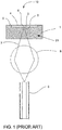
- FIG. 1 shows a prior art construction of a Fabry-Perot sensor 10 for measuring pressure.
- a bi-directional fiber optic 9 guides the light signal 7 toward a Fabry-Perot pressure chip 21.
- the pressure chip 21 is made of from a glass substrate 1.
- One first partially reflective mirror 2 is deposited within a recessed cavity 5 performed on the top surface of the glass substrate 1.
- a second deformable mirror 3 is bonded or welded to the glass substrate 1. Both mirrors 2, 3, spaced by a distance given by the depth of the recessed cavity 5, constitutes a Fabry-Perot cavity 6.
- the second mirror 3 bows toward first mirror 2 as function of an applied pressure.
- FP cavity length 6 is then an unambiguous function of pressure.
- the deflection of the diaphragm as a function of the pressure is usually of the order of 2 nm/mmHg.
- the pressure chip 21 needs to be packaged so that the light signal travelling into the optical fiber 9 is directed from the fiber to the Fabry-Perot cavity 6, and back to the optical fiber 9.
- an optical lens 8 can be considered, this does not yet resolve the method for attaching the fiber 9 to the glass substrate so that no environmental parasitic effect will be detrimental to the pressure measurement.
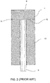
- FIG. 2 illustrates another prior art where the fiber optic 9 is brought in close proximity to the Fabry-Perot cavity 6, usually less than 200 microns, so that no optical system is needed to bring the light in and out of the Fabry-Perot cavity 6.
- the presence of the adhesive 11 directly on the back side 12 of the glass substrate 1 makes this design very sensitive to moisture induced drift. Also, the insertion of the optical fiber 9 into the tube 13 contributes increasing the production cost.
- FIG. 3A shows another prior art design where the method for assembling the fiber optic 9 to the pressure chip 21 is achieved at the chip level.
- the production cost is thus fairly acceptable.
- the moisture induced swelling of the adhesive 23 will induce a strong bending moment 24, as illustrated by FIG. 3B , sufficient to bend the pressure chip so that the diaphragm 25 significantly deflects toward the glass surface 26, resulting in a pressure drift. Because the funnel is wide open, the pulling force required to pull the pressure chip off the fiber is significantly reduced.
- Fabry-Perot pressure sensors Another drawback of Fabry-Perot pressure sensors is their sensitivity to temperature. For the sensors to find practical uses in medical fields, it is of importance to provide a method for compensating thermal shift that occurs as a result of the differences in the coefficient of thermal expansion of materials used to build the sensor.
- the invention provides a miniature chip design according to claims 1 and 2 and a pressure chip manufacturing method according to claim 7 that renders the chip less sensitive to
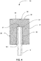
- the sensor 30 comprises a pressure chip 36 that is coupled to an optical fiber 9.
- the pressure chip 36 comprises a recessed cavity 39 covered by a diaphragm 38 forming the Fabry-Perot cavity 35.
- a glass substrate 31, 500 microns in thickness is first drilled with tiny holes 33 accommodating the fiber optic 9 to a thickness of 300 microns. It is understood by those skilled in the art that other combination of glass substrate thickness and drilling depth could also be used.
- the holes 33 can be drilled with an excimer laser tuned at 193nm.
- the interest of drilling holes using an excimer laser is that the walls 32 of the holes 33 exhibit a deviation from the perpendicular limited to about 6 degrees.
- the quantity of adhesive 34 filling the hole is much less than with prior art and hence, the bending moment that is exerted as a result of adhesive swelling due to moisture has significant reduced impact on the variation of the Fabry-Perot cavity 35.
- the drift is reduced by an order of magnitude, making this design perfectly well suited for medical applications.
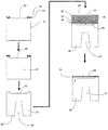
- FIG. 5 a method for producing the pressure chip 36 of sensor 30 is shown in FIG. 5 .
- a code 7740 glass substrate 41, 500 microns, thick is first coated with a layer of chrome 42, 1000 Angstroms of thickness. This chrome layer will serve as a mask for etching the Fabry-Perot cavity 45 on the first surface 44 of the glass substrate.
- the chrome layer is then spin coated with a photoresist 43. The photoresist is then exposed with a mask that corresponds to the diameter of the Fabry-Perot cavity 45.
- the diameter of the Fabry-Perot cavity 45 can be of various sizes, a diameter of 300 microns has been found to be a good trade-off for minimizing the size of the cavity 45 while maintaining adequate deflection of the diaphragm as a function of the applied pressure.
- the photoresist 43 is exposed, the photoresist is developed, which then exposes selected portions of chrome. Exposed chrome is etched-off using chrome etch solution composed of one part of HCL and one part of glycerin. At this point, selected portions of the 7740 glass substrate 41 is ready for being etched down to the desired depth to form the Fabry-Perot cavity 45.
- Fabry-Perot cavities 45 of 300 microns diameter are etched down to a depth of 18 microns using a buffered HF solution composed of four parts of a mixture of 3ml of water and 2g of NH4F plus 1 part of 48% HF solution.
- a buffered HF solution composed of four parts of a mixture of 3ml of water and 2g of NH4F plus 1 part of 48% HF solution.
- the substrate is removed and rinsed into de-ionized water for being coated with a semi-reflective mirror 46 constituting the first mirror of the Fabry-Perot cavity 45.
- the semi-reflective mirror 46 can be made of various oxide materials, such as a quarter wavelength of Ta2O5.
- the glass substrate 41 is now ready for being drilled on the second surface 48 of the substrate using an excimer laser.
- a silicon substrate 49 that contains the diaphragm 38 is anodically bonded on the first surface 50 of the glass substrate 41.
- the silicon substrate 49 will then have to be thinned to unveil the diaphragm 38.
- the thickness of diaphragm 38 is usually controlled by using so-called etch stop layers.
- the most common etch stop makes use of heavily boron doped (p++) epi layer.
- a p++ layer is grown on the surface of a lightly doped silicon substrate to a thickness equal to the desired diaphragm thickness.
- lightly doped portion of the silicon can be removed by mechanical grinding and chemical etching, such as in Ethylene Diamine Pyrocathecol (EDP) solution.
- EDP Ethylene Diamine Pyrocathecol
- the thickness of the diaphragm is somewhat difficult to control. Also, one can hardly obtain a mirror-like surface because the grinded surface will be reproduced on the surface of the diaphragm, diminished by similar factor of 100. Also, it is not recommended to use p++ layer as a diaphragm as there may have internal residual stresses. Internal residual stresses along with irregular diaphragm surface contribute reducing the yield strength of the diaphragm, hence reducing the maximum pressure before diaphragm failure.
- SOI substrate 55 is made of the thin silicon substrate 49 (device) thermally bonded to another thick silicon substrate 52 (handle), with an insulating silicon dioxide layer in-between 51. SOI wafers 55 are available off-the-shelf with various device 49 thicknesses. In this case, the silicon dioxide layer will act as a first etch-stop.
- the handle 52 can be removed by grinding a first portion of its total thickness, followed by a chemical etching using an EDP solution.
- the etching process slows-down by a factor of at least 10000.
- the silicon dioxide layer 51 is finally removed using a HF-buffered solution.
- the silicon is etched 10000 times slower than SiO2.
- the final pressure chip 36 then comprises a mirror-like diaphragm surface, with grinding reproduced irregularity reduced by a factor of more than 1000000, also providing perfect control of diaphragm thickness.
- a reflective layer may be deposited on an internal surface of the diaphragm so as to obtain a Fabry-Perot cavity 45 with the desired characteristics (such as Finesse) and to prevent the formation of a parasitic cavity between the internal and external surfaces of the diaphragm.
- Such reflective layer can be a metallic layer such as, for example, a layer of chromium.
- the substrate is diced to single out the pressure chips 36.
- the pressure chips 36 are ready for receiving the optical fiber 9.
- the Fabry-Perot cavity 45 of the pressure chip 36 can also be obtained by forming the recessed cavity 39 in the diaphragm 38 instead of forming the recessed cavity 39 in the glass substrate 41.
- Sensor 60 comprises a pressure chip 68 coupled to an optical fiber 65.
- the use of a silicon substrate 61, 300 microns thick, etched with narrow etched hole 62 for receiving the optical fiber 65 differentiates this sensor 60 from sensor 30. It is indeed possible to etch vertical holes 62 into silicon substrates 61 with proper preferential etching and crystallography orientation. For example, one can etch similar holes 62 by selecting a silicon substrate 61 with (110) orientation. Preferential chemical etching using EDP, KOH, TMAH or dry etching using RIE or DRIE can produce vertical walls defined by the (111) planes as known by those skilled in the art.
- those pressure chips 68 can be produced by first etching the Fabry-Perot cavity 45 followed by the deposition of a semi-reflective mirror 46. Silicon substrate 61 with etched holes 62 is then anodically bonded to the rear face 63 of the glass substrate 63. The diaphragm 64 can then be bonded to the other surface of the glass substrate 63. Techniques similar to those illustrated in Fig. 5 and described above for producing the diaphragm can be used to obtain final diaphragm 64.
- Sensor 30 and sensor 60 may suffer from thermal sensitivity.
- the coefficient of thermal expansion (CTE) of silicon and Pyrex 7740 are 2.4x10 -6 °C -1 and 3.1x10 -6 °C -1 respectively.
- CTE coefficient of thermal expansion
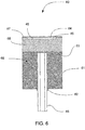
- FIG. 7 A fiber optic Fabry-Perot pressure sensor 70 less sensitive to thermal shift, by means of thermal compensation, is shown in FIG. 7 .
- Thermal compensation is achieved by depositing on.the external surface 71 of the diaphragm 72 a material 73 exhibiting a CTE higher than the substrate 74.
- a fairly thin layer of aluminum 73 can be deposited to compensate for thermal shift.
- bending stresses dominate tensile stresses.
- the outer surface of the diaphragm when bowing downward, is in tension near the edge 75 of the diaphragm, while it is in compression in the center 76.
- Depositing a high CTE material on the whole surface of the diaphragm is not efficient because the central portion is in compression. For some specific designs, the deposition of a high CTE material may even accentuate the thermal shift.
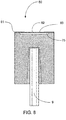
- the senor 80 shown in FIG. 8 has a diaphragm 83 on which, according to the invention, a high CTE compensating material 81 have been deposited strictly on the edge portion of the diaphragm 83.
- a high CTE compensating material 81 For optimal results, as much as 2/3 of the central portion 82 of the diaphragm 83 should not contain any compensating material 81.
- the compensating material 81 should be deposited with a donut-like shape, the diameter of the center 82 being roughly equals to 2/3 times the total diameter of the effective diaphragm 83, which is the diameter of the recessed cavity 45.
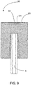
- Fabry Perot pressure sensor 90 illustrated in Fig. 9 , has a high CTE material 91 deposited on the center of the internal surface.
- the diameter of the layer 91 roughly equals 2/3 times the total diameter of the effective diaphragm 83.
- thinner high CTE material can be deposited on the central portion 92 of the diaphragm 93 to obtain similar thermal compensation. Compensating the thermal shift from the internal surface of the diaphragm 93 is more efficient than compensating from the external surface of the diaphragm 93.
- compensating from the external surface allows the tuning of the thickness, hence obtaining perfect compensation in all cases and hence increasing the yield. Tuning can be achieved by depositing a slightly thicker layer of compensating material 81, followed by post etching.
- low CTE material would be less efficient for compensating thermal shift, the difference in the CTE of silicon diaphragm and compensating material being limited to less than 2.4x10 -6 °C -1 , low CTE material can nonetheless be used for that purpose. From the above teaching, those skilled in the art will understand that thermal compensation can be obtained by depositing such low CTE material in ways opposite to those described herein above. According to the invention, one could deposit a layer of low CTE silicon dioxide material on the central portion of the outer surface of the diaphragm, and oppositely, one could deposit the said low CTE material on the edge of the inner surface of the diaphragm.
- sensors 30, 60, 80 and 90 may suffer from a change in sensitivity when immersed into a water based solution.
- a protection against etching of the exposed silicon By way of non-limiting example, one can deposit a thin layer of chromium for covering the exposed section, being understood that any other materials performing the same would eliminate silicon etching. For medical. applications, it would be more desirable to deposit a thin layer of titanium or silicon oxide. The thickness of titanium required for protecting the silicon against etching, when immersed into water or blood, can be made fairly thin. To ease the production of the sensor, it would be very acceptable to cover the whole diaphragm with such a titanium layer. The titanium can be deposited on the external surface of the diaphragm prior to depositing the compensating material. For biocompatibility purposes, a preferred method involves the deposition of the titanium layer on top of both the exposed silicon diaphragm, and the high CTE temperature compensation material.
Landscapes
- Physics & Mathematics (AREA)
- General Physics & Mathematics (AREA)
- Measuring Fluid Pressure (AREA)
- Pressure Sensors (AREA)
Applications Claiming Priority (4)
| Application Number | Priority Date | Filing Date | Title |
|---|---|---|---|
| US63775504P | 2004-12-22 | 2004-12-22 | |
| US11/138,423 US7689071B2 (en) | 2004-12-22 | 2005-05-27 | Fiber optic pressure sensor for catheter use |
| EP05821033A EP1834164A4 (en) | 2004-12-22 | 2005-12-12 | FIBER OPTIC PRESSURE SENSOR FOR CATHETER |
| PCT/CA2005/001883 WO2006066393A1 (en) | 2004-12-22 | 2005-12-12 | A fiber optic pressure sensor for catheter use |
Related Parent Applications (1)
| Application Number | Title | Priority Date | Filing Date |
|---|---|---|---|
| EP05821033A Division EP1834164A4 (en) | 2004-12-22 | 2005-12-12 | FIBER OPTIC PRESSURE SENSOR FOR CATHETER |
Publications (2)
| Publication Number | Publication Date |
|---|---|
| EP3141881A1 EP3141881A1 (en) | 2017-03-15 |
| EP3141881B1 true EP3141881B1 (en) | 2020-05-06 |
Family
ID=36595841
Family Applications (2)
| Application Number | Title | Priority Date | Filing Date |
|---|---|---|---|
| EP16192419.6A Expired - Lifetime EP3141881B1 (en) | 2004-12-22 | 2005-12-12 | A fiber optic pressure sensor for catheter use |
| EP05821033A Withdrawn EP1834164A4 (en) | 2004-12-22 | 2005-12-12 | FIBER OPTIC PRESSURE SENSOR FOR CATHETER |
Family Applications After (1)
| Application Number | Title | Priority Date | Filing Date |
|---|---|---|---|
| EP05821033A Withdrawn EP1834164A4 (en) | 2004-12-22 | 2005-12-12 | FIBER OPTIC PRESSURE SENSOR FOR CATHETER |
Country Status (5)
| Country | Link |
|---|---|
| US (1) | US7689071B2 (enExample) |
| EP (2) | EP3141881B1 (enExample) |
| JP (1) | JP4994244B2 (enExample) |
| CA (1) | CA2591787C (enExample) |
| WO (1) | WO2006066393A1 (enExample) |
Cited By (3)
| Publication number | Priority date | Publication date | Assignee | Title |
|---|---|---|---|---|
| US11819700B2 (en) | 2021-08-06 | 2023-11-21 | Solo Pace Inc. | Systems, methods, and apparatus for external cardiac pacing |
| US11872403B2 (en) | 2021-08-06 | 2024-01-16 | Solo Pace Inc. | Systems, methods, and apparatus for external cardiac pacing |
| US12357833B2 (en) | 2023-08-01 | 2025-07-15 | Merit Medical Systems, Inc. | Systems, methods, and apparatus for ambulatory cardiac pacing |
Families Citing this family (91)
| Publication number | Priority date | Publication date | Assignee | Title |
|---|---|---|---|---|
| US7455666B2 (en) | 2001-07-13 | 2008-11-25 | Board Of Regents, The University Of Texas System | Methods and apparatuses for navigating the subarachnoid space |
| US8075498B2 (en) | 2005-03-04 | 2011-12-13 | Endosense Sa | Medical apparatus system having optical fiber load sensing capability |
| US8182433B2 (en) * | 2005-03-04 | 2012-05-22 | Endosense Sa | Medical apparatus system having optical fiber load sensing capability |
| EP3028645B1 (en) | 2005-08-01 | 2019-09-18 | St. Jude Medical International Holding S.à r.l. | Medical apparatus system having optical fiber load sensing capability |
| US8048063B2 (en) * | 2006-06-09 | 2011-11-01 | Endosense Sa | Catheter having tri-axial force sensor |
| US8567265B2 (en) | 2006-06-09 | 2013-10-29 | Endosense, SA | Triaxial fiber optic force sensing catheter |
| US8157789B2 (en) * | 2007-05-24 | 2012-04-17 | Endosense Sa | Touch sensing catheter |
| US8622935B1 (en) | 2007-05-25 | 2014-01-07 | Endosense Sa | Elongated surgical manipulator with body position and distal force sensing |
| GB0724411D0 (en) | 2007-12-14 | 2008-01-30 | Stfc Science & Technology | Optical sensor |
| US8298227B2 (en) * | 2008-05-14 | 2012-10-30 | Endosense Sa | Temperature compensated strain sensing catheter |
| RU2478338C2 (ru) | 2008-09-11 | 2013-04-10 | Эсист Медикал Системз, Инк. | Устройство и способ доставки физиологического датчика |
| US20100114063A1 (en) * | 2008-11-04 | 2010-05-06 | Angiodynamics, Inc. | Catheter injection monitoring device |
| JP5347656B2 (ja) * | 2009-03-31 | 2013-11-20 | 日本ゼオン株式会社 | カテーテル |
| US8151648B2 (en) * | 2009-08-03 | 2012-04-10 | University Of Maryland | Ultra-miniature fiber-optic pressure sensor system and method of fabrication |
| EP2485638B1 (en) | 2009-10-07 | 2016-11-30 | Endophys Holdings, LLC | Pressure-sensing medical device |
| WO2011053766A1 (en) * | 2009-10-30 | 2011-05-05 | Advanced Bionics, Llc | Steerable stylet |
| US8771289B2 (en) * | 2009-12-21 | 2014-07-08 | Acist Medical Systems, Inc. | Thrombus removal device and system |
| US8478384B2 (en) | 2010-01-19 | 2013-07-02 | Lightlab Imaging, Inc. | Intravascular optical coherence tomography system with pressure monitoring interface and accessories |
| US8764678B2 (en) * | 2010-02-01 | 2014-07-01 | University Of Limerick | Pressure sensor with an interferometric sensor and an in-fiber bragg grating reference sensor |
| CA3090851C (en) * | 2010-03-15 | 2023-03-07 | The Board Of Trustees Of The Leland Stanford Junior University | Optical-fiber-compatible acoustic sensor |
| CN101832832B (zh) * | 2010-05-28 | 2012-02-22 | 天津大学 | 光纤法布里-珀罗压力传感器及其制作方法 |
| US8966988B2 (en) | 2010-08-03 | 2015-03-03 | University Of Maryland | Ultra-miniature fiber-optic pressure sensor system and method of fabrication |
| CA2808202C (en) | 2010-11-09 | 2013-11-05 | Opsens Inc. | Guidewire with internal pressure sensor |
| US8752435B2 (en) * | 2011-03-09 | 2014-06-17 | Claude Belleville | Miniature high sensitivity pressure sensor |
| CN103620710B (zh) | 2011-04-04 | 2016-10-05 | 魏德曼电气技术公司 | 用于监测变压器老化的夹持力传感器组件 |
| EP2696777B1 (en) * | 2011-04-14 | 2020-08-05 | St. Jude Medical International Holding S.à r.l. | Catheter assembly with optical force sensor |
| CN103796578B (zh) | 2011-05-11 | 2016-08-24 | 阿西斯特医疗系统有限公司 | 血管内感测方法和系统 |
| US20140088890A1 (en) * | 2011-05-31 | 2014-03-27 | Japan Science And Technology Agency | Method for temperature compensation in sensor, computation program for method for temperature compensation, computation processing device, and sensor |
| US9510786B2 (en) * | 2011-06-22 | 2016-12-06 | Biosense Webster (Israel) Ltd. | Optical pressure measurement |
| US20130039616A1 (en) * | 2011-08-08 | 2013-02-14 | Gary Shambat | Optical Fibers Functionalized with Photonic Crystal Resonant Optical Structures |
| CN102384809B (zh) * | 2011-08-09 | 2013-05-08 | 天津大学 | 无胶封装的高稳定性光纤法-珀压力传感器及制作方法 |
| US9405078B2 (en) | 2011-08-30 | 2016-08-02 | Opsens Inc. | Method for disposable guidewire optical connection |
| US8936401B2 (en) | 2011-08-30 | 2015-01-20 | Claude Belleville | Method for disposable guidewire optical connection |
| US10463259B2 (en) | 2011-10-28 | 2019-11-05 | Three Rivers Cardiovascular Systems Inc. | System and apparatus comprising a multi-sensor catheter for right heart and pulmonary artery catheterization |
| WO2013061280A1 (en) | 2011-10-28 | 2013-05-02 | Hemodynamix Medical Systems Inc. | Fluid temperature and flow sensor apparatus and system for cardiovascular and other medical applications |
| CN103162878B (zh) * | 2011-12-11 | 2015-12-09 | 黄辉 | 一种光纤压力传感器及其制备方法 |
| EP2626680B1 (en) * | 2012-02-07 | 2015-10-07 | Sensoptic SA | Optical force sensing element and microsurgical instrument |
| DE102012207053A1 (de) | 2012-04-27 | 2013-10-31 | Abiomed Europe Gmbh | Intravasale rotationsblutpumpe |
| CA2911446C (en) | 2012-05-25 | 2020-10-13 | Vascular Imaging Corporation | Optical fiber pressure sensor |
| CN105142506A (zh) | 2012-08-27 | 2015-12-09 | 波士顿科学国际有限公司 | 压力感测医疗器械及医疗器械系统 |
| CA2895761A1 (en) | 2012-12-21 | 2014-06-26 | Volcano Corporation | Pressure-sensing intravascular devices, systems, and methods |
| US10028666B2 (en) | 2013-03-15 | 2018-07-24 | Boston Scientific Scimed, Inc. | Pressure sensing guidewire |
| AU2014256932B2 (en) | 2013-04-26 | 2017-01-05 | Wicor Holding Ag | Fiber-grating sensors having longitudinal-strain-inducing jackets and sensor systems and structures including such sensors |
| EP2999400B1 (en) | 2013-05-22 | 2022-08-03 | Boston Scientific Scimed, Inc. | Pressure sensing guidewire systems including an optical connector cable |
| CN103344381B (zh) * | 2013-06-08 | 2016-03-30 | 天津大学 | 具有多台阶的宽范围光纤真空传感器及其制作方法 |
| WO2015013646A1 (en) | 2013-07-26 | 2015-01-29 | Boston Scientific Scimed, Inc. | Ffr sensor head design that minimizes stress induced pressure offsets |
| US10835182B2 (en) | 2013-08-14 | 2020-11-17 | Boston Scientific Scimed, Inc. | Medical device systems including an optical fiber with a tapered core |
| WO2015051003A1 (en) | 2013-10-04 | 2015-04-09 | Vascular Imaging Corporation | Imaging techniques using an imaging guidewire |
| WO2015057518A1 (en) | 2013-10-14 | 2015-04-23 | Boston Scientific Scimed, Inc. | Pressure sensing guidewire and methods for calculating fractional flow reserve |
| US10537255B2 (en) | 2013-11-21 | 2020-01-21 | Phyzhon Health Inc. | Optical fiber pressure sensor |
| WO2015142623A1 (en) | 2014-03-18 | 2015-09-24 | Boston Scientific Scimed, Inc. | Pressure sensing guidewires |
| US9429713B2 (en) | 2014-04-17 | 2016-08-30 | Boston Scientific Scimed, Inc. | Self-cleaning optical connector |
| KR101509397B1 (ko) | 2014-04-30 | 2015-04-08 | 성균관대학교산학협력단 | 광섬유를 이용한 힘 센서 및 이를 이용한 카테터 |
| KR101726024B1 (ko) * | 2014-04-30 | 2017-04-12 | 성균관대학교산학협력단 | 광섬유를 이용한 힘 센서 및 이를 이용한 카테터 |
| CN106659393B (zh) | 2014-06-04 | 2021-02-19 | 波士顿科学国际有限公司 | 压力偏移减少的压力感测导丝系统 |
| US10244951B2 (en) | 2014-06-10 | 2019-04-02 | Acist Medical Systems, Inc. | Physiological sensor delivery device and method |
| US9562844B2 (en) | 2014-06-30 | 2017-02-07 | Baker Hughes Incorporated | Systems and devices for sensing corrosion and deposition for oil and gas applications |
| WO2016009317A1 (en) | 2014-07-13 | 2016-01-21 | Three Rivers Cardiovascular Systems Inc. | System and apparatus comprising a multisensor guidewire for use in interventional cardiology |
| EP3174455B1 (en) | 2014-08-01 | 2021-10-27 | Boston Scientific Scimed, Inc. | Pressure sensing guidewires |
| US10080872B2 (en) | 2014-11-04 | 2018-09-25 | Abbott Cardiovascular Systems Inc. | System and method for FFR guidewire recovery |
| US10258240B1 (en) | 2014-11-24 | 2019-04-16 | Vascular Imaging Corporation | Optical fiber pressure sensor |
| WO2016090272A1 (en) | 2014-12-05 | 2016-06-09 | Boston Scientific Scimed, Inc. | Pressure sensing guidewires |
| CN106152961B (zh) * | 2015-01-16 | 2019-02-12 | 黄辉 | 一种光纤应变传感器及其制备方法 |
| CN104614104B (zh) * | 2015-01-19 | 2018-01-30 | 中北大学 | 光纤法珀压力传感器及其制作方法 |
| DE102015000773B4 (de) | 2015-01-26 | 2021-09-16 | Karl Storz Se & Co. Kg | Endoskop und Verfahren zur Herstellung eines Endoskops |
| CN105987784B (zh) * | 2015-01-27 | 2019-05-24 | 成都凯天电子股份有限公司 | 高真空光纤f-p压力传感器 |
| CN106323515A (zh) * | 2015-07-10 | 2017-01-11 | 成都凯天电子股份有限公司 | 光纤f-p腔应力释放压力传感器 |
| US11857345B2 (en) * | 2015-09-04 | 2024-01-02 | Boston Scientific Scimed, Inc. | Pressure sensing guidewires |
| CN105571769B (zh) * | 2015-12-17 | 2019-01-15 | 天津求实飞博科技有限公司 | 新型光纤高压传感器 |
| US11445937B2 (en) | 2016-01-07 | 2022-09-20 | St. Jude Medical International Holding S.À R.L. | Medical device with multi-core fiber for optical sensing |
| US11058307B2 (en) | 2016-02-23 | 2021-07-13 | Boston Scientific Scimed, Inc. | Pressure sensing guidewire systems including an optical connector cable |
| CN105806543A (zh) * | 2016-05-16 | 2016-07-27 | 中北大学 | 一种光纤法珀高温压力传感器 |
| ES2898827T3 (es) | 2016-06-06 | 2022-03-09 | Abiomed Inc | Conjunto de bomba de sangre con sensor y protector de sensor |
| US11272847B2 (en) | 2016-10-14 | 2022-03-15 | Hemocath Ltd. | System and apparatus comprising a multi-sensor catheter for right heart and pulmonary artery catheterization |
| KR102030237B1 (ko) * | 2017-08-02 | 2019-10-08 | 재단법인 아산사회복지재단 | 광섬유를 이용한 선단의 압력 감지 카테터 및 카테터 시스템 |
| US11564581B2 (en) | 2017-08-03 | 2023-01-31 | Boston Scientific Scimed, Inc. | Methods for assessing fractional flow reserve |
| CN109870255B (zh) | 2017-12-05 | 2023-09-12 | 北京佰为深科技发展有限公司 | 法珀传感器及其制造方法 |
| EP4070720B1 (en) | 2018-02-23 | 2023-11-08 | Boston Scientific Scimed, Inc. | Methods for assessing a vessel with sequential physiological measurements |
| WO2019183432A1 (en) | 2018-03-23 | 2019-09-26 | Boston Scientific Scimed, Inc. | Medical device with pressure sensor |
| EP3769056A1 (en) | 2018-03-23 | 2021-01-27 | The Board of Trustees of the Leland Stanford Junior University | Diaphragm-based fiber acoustic sensor |
| US11559213B2 (en) | 2018-04-06 | 2023-01-24 | Boston Scientific Scimed, Inc. | Medical device with pressure sensor |
| CN108498065B (zh) * | 2018-04-17 | 2021-04-06 | 温州医科大学附属眼视光医院 | 一种泪道泪液泵引流功能检测仪及其检测方法 |
| EP4643763A3 (en) | 2018-04-18 | 2025-12-10 | Boston Scientific Scimed, Inc. | System for assessing a vessel with sequential physiological measurements |
| PL3781026T3 (pl) | 2018-04-20 | 2022-07-11 | Acist Medical Systems, Inc. | Ocena naczynia |
| DE102018124753A1 (de) * | 2018-10-08 | 2020-04-09 | fos4X GmbH | Temperaturkompensierter faseroptischer Sensor und Verfahren zur Druckmessung |
| WO2020158572A1 (ja) | 2019-01-30 | 2020-08-06 | 日本ゼオン株式会社 | 大動脈内バルーンカテーテル |
| EP4041071A4 (en) | 2019-09-30 | 2023-10-18 | HemoCath Ltd. | CATHETER WITH MULTIPLE SENSORS FOR RIGHT HEART AND PULMONARY ARTERY CATHETIZATION |
| US12109373B2 (en) | 2020-09-15 | 2024-10-08 | Boston Scientific Scimed, Inc. | Devices and systems for an endoscopic procedure |
| CN112697339B (zh) * | 2020-11-26 | 2022-05-06 | 桂林电子科技大学 | 一种高强度耐高温快响应光纤气压传感探头 |
| US12087000B2 (en) | 2021-03-05 | 2024-09-10 | Boston Scientific Scimed, Inc. | Systems and methods for vascular image co-registration |
| US12504320B2 (en) | 2022-04-05 | 2025-12-23 | The Board Of Trustees Of The Leland Stanford Junior University | Self-aligning optical acoustic sensors |
Family Cites Families (33)
| Publication number | Priority date | Publication date | Assignee | Title |
|---|---|---|---|---|
| US3590638A (en) * | 1969-10-22 | 1971-07-06 | Bendix Corp | Thermoelectric pressure sensor |
| JPS5921495B2 (ja) | 1977-12-15 | 1984-05-21 | 株式会社豊田中央研究所 | 細管型圧力計 |
| SU746218A1 (ru) * | 1978-03-06 | 1980-07-07 | Уфимский авиационный институт им. Орджоникидзе | Способ механической компенсации температурной зависимости чувствительности интегральных датчиков малых давлений |
| DE3329385A1 (de) * | 1983-08-13 | 1985-02-28 | Seitz-Filter-Werke Theo & Geo Seitz GmbH und Co, 6550 Bad Kreuznach | Asbestfreie filterschicht |
| US4576181A (en) | 1984-05-09 | 1986-03-18 | Utah Medical Products | Disposable pressure transducer apparatus for medical use |
| US4678904A (en) | 1984-07-06 | 1987-07-07 | Technology Dynamics, Inc. | Optical measuring device using a spectral modulation sensor having an optically resonant structure |
| GB8506589D0 (en) * | 1985-03-14 | 1985-04-17 | Ici Plc | Pressure sensor |
| JPS61235731A (ja) * | 1985-04-11 | 1986-10-21 | Sharp Corp | 感圧素子 |
| US4726232A (en) * | 1986-06-02 | 1988-02-23 | Gould Inc. | Temperature coefficient compensated pressure transducer |
| US4771782A (en) | 1986-11-14 | 1988-09-20 | Millar Instruments, Inc. | Method and assembly for introducing multiple catheters into a biological vessel |
| US4991925A (en) * | 1988-10-04 | 1991-02-12 | Metricor | Spectrum shifting optical switch |
| US4983824A (en) * | 1989-07-06 | 1991-01-08 | Metricor Inc. | Optically resonant sensor with increased monotonic range |
| EP0419021A3 (en) * | 1989-08-30 | 1991-10-09 | Schlumberger Industries Limited | Sensors with vibrating elements |
| EP0460357A3 (en) * | 1990-06-08 | 1992-07-29 | Landis & Gyr Betriebs Ag | Device for optical measurement of pressure differences |
| US5275053A (en) * | 1991-08-21 | 1994-01-04 | Fiberoptic Sensor Technologies, Inc. | Fiber optic pressure sensor systems |
| FI98095C (fi) * | 1992-05-19 | 1997-04-10 | Vaisala Technologies Inc Oy | Fabry-Perot resonaattoriin perustuva optinen voima-anturi, jossa ilmaisimen osana toimii pyyhkäisevä Fabry-Perot resonaattori |
| CA2074289C (en) | 1992-07-21 | 1999-09-14 | Claude Belleville | Fabry-perot optical sensing device for measuring a physical parameter |
| US5315110A (en) * | 1993-06-29 | 1994-05-24 | Abb Vetco Gray Inc. | Metal cup pressure transducer with a support having a plurality of thermal expansion coefficients |
| GB2338059B (en) * | 1998-05-20 | 2000-03-08 | Bookham Technology Ltd | An optically addressed sensing system |
| US6626043B1 (en) | 2000-01-31 | 2003-09-30 | Weatherford/Lamb, Inc. | Fluid diffusion resistant glass-encased fiber optic sensor |
| US6738145B2 (en) * | 2000-04-14 | 2004-05-18 | Shipley Company, L.L.C. | Micromachined, etalon-based optical fiber pressure sensor |
| US6602427B1 (en) * | 2000-08-28 | 2003-08-05 | Xiang Zheng Tu | Micromachined optical mechanical modulator based transmitter/receiver module |
| US6925213B2 (en) * | 2001-03-09 | 2005-08-02 | University Of Cincinnati | Micromachined fiber optic sensors |
| CA2445404A1 (en) | 2001-04-25 | 2002-10-31 | Mayo Foundation For Medical Education And Research | Microsensor for physiological pressure measurement |
| US6894787B2 (en) | 2001-12-21 | 2005-05-17 | Honeywell International Inc. | Optical pressure sensor |
| US7428054B2 (en) * | 2002-10-15 | 2008-09-23 | University Of Maryland | Micro-optical sensor system for pressure, acceleration, and pressure gradient measurements |
| DE10314910A1 (de) * | 2003-04-01 | 2004-11-11 | Siemens Ag | Drucksensor |
| US7054011B2 (en) | 2003-09-04 | 2006-05-30 | Virginia Tech Intellectual Properties, Inc. | Optical fiber pressure and acceleration sensor fabricated on a fiber endface |
| US6823738B1 (en) * | 2003-10-15 | 2004-11-30 | Marek T. Wlodarczyk | Temperature compensated fiber-optic pressure sensor |
| US7173713B2 (en) * | 2004-03-04 | 2007-02-06 | Virginia Tech Intellectual Properties, Inc. | Optical fiber sensors for harsh environments |
| GB0408073D0 (en) * | 2004-04-08 | 2004-05-12 | Council Cent Lab Res Councils | Optical sensor |
| US7187453B2 (en) | 2004-04-23 | 2007-03-06 | Opsens Inc. | Optical MEMS cavity having a wide scanning range for measuring a sensing interferometer |
| JP5028410B2 (ja) * | 2005-04-29 | 2012-09-19 | ボード オブ トラスティーズ オブ ザ レランド スタンフォード ジュニア ユニバーシティ | 高感度ファイバ適合光音響センサ |
-
2005
- 2005-05-27 US US11/138,423 patent/US7689071B2/en active Active
- 2005-12-12 WO PCT/CA2005/001883 patent/WO2006066393A1/en not_active Ceased
- 2005-12-12 CA CA2591787A patent/CA2591787C/en not_active Expired - Lifetime
- 2005-12-12 JP JP2007547119A patent/JP4994244B2/ja not_active Expired - Lifetime
- 2005-12-12 EP EP16192419.6A patent/EP3141881B1/en not_active Expired - Lifetime
- 2005-12-12 EP EP05821033A patent/EP1834164A4/en not_active Withdrawn
Non-Patent Citations (1)
| Title |
|---|
| None * |
Cited By (4)
| Publication number | Priority date | Publication date | Assignee | Title |
|---|---|---|---|---|
| US11819700B2 (en) | 2021-08-06 | 2023-11-21 | Solo Pace Inc. | Systems, methods, and apparatus for external cardiac pacing |
| US11872403B2 (en) | 2021-08-06 | 2024-01-16 | Solo Pace Inc. | Systems, methods, and apparatus for external cardiac pacing |
| US12161872B2 (en) | 2021-08-06 | 2024-12-10 | Solo Pace Inc. | Systems, methods, and apparatus for external cardiac pacing |
| US12357833B2 (en) | 2023-08-01 | 2025-07-15 | Merit Medical Systems, Inc. | Systems, methods, and apparatus for ambulatory cardiac pacing |
Also Published As
| Publication number | Publication date |
|---|---|
| WO2006066393A1 (en) | 2006-06-29 |
| CA2591787C (en) | 2016-01-19 |
| US20060133715A1 (en) | 2006-06-22 |
| JP2008524606A (ja) | 2008-07-10 |
| JP4994244B2 (ja) | 2012-08-08 |
| EP3141881A1 (en) | 2017-03-15 |
| US7689071B2 (en) | 2010-03-30 |
| EP1834164A4 (en) | 2011-05-04 |
| CA2591787A1 (en) | 2006-06-29 |
| EP1834164A1 (en) | 2007-09-19 |
Similar Documents
| Publication | Publication Date | Title |
|---|---|---|
| EP3141881B1 (en) | A fiber optic pressure sensor for catheter use | |
| US6868736B2 (en) | Ultra-miniature optical pressure sensing system | |
| CA2819564C (en) | A miniature high sensitivity pressure sensor | |
| US7421905B2 (en) | Optical sensor with co-located pressure and temperature sensors | |
| US7684657B2 (en) | Single piece Fabry-Perot optical sensor and method of manufacturing the same | |
| CA2770937C (en) | Actuator for moving a micro mechanical element | |
| US7697798B2 (en) | Fiber optic pressure sensors and catheters | |
| US20110190640A1 (en) | Pressure sensor with an interferometric sensor and an in-fiber Bragg grating reference sensor | |
| EP2233903A2 (en) | High temperature optical pressure sensor and method of fabrication of the same | |
| AU3947199A (en) | An optically addressed sensing system | |
| EP1942324A1 (en) | Optical sensor with co-located pressure and temperature sensors | |
| CN116295555A (zh) | 一种光纤f-p腔mems温-压复合传感器及其制备方法 | |
| EP0997721B1 (en) | Pressure sensor and a method of manufacturing the same | |
| Zhu | Miniature fiber-optic sensors for high-temperature harsh environments | |
| Brace | Opto-Mechanical Analysis of a Harsh Environment MEMS Fabry-Perot Pressure Sensor | |
| CN121176878A (zh) | 一种基于柔性敏感膜的光纤颅内温压传感探头、系统及方法 | |
| Kim | Application of micromachining techniques for Fabry-Perot cavity based microsensors | |
| Bae | Polymer based miniature Fabry-Perot pressure sensors with temperature compensation: Modeling, fabrication, and experimental studies | |
| Wang | Master of Science in Electrical Engineering |
Legal Events
| Date | Code | Title | Description |
|---|---|---|---|
| PUAI | Public reference made under article 153(3) epc to a published international application that has entered the european phase |
Free format text: ORIGINAL CODE: 0009012 |
|
| STAA | Information on the status of an ep patent application or granted ep patent |
Free format text: STATUS: THE APPLICATION HAS BEEN PUBLISHED |
|
| AC | Divisional application: reference to earlier application |
Ref document number: 1834164 Country of ref document: EP Kind code of ref document: P |
|
| AK | Designated contracting states |
Kind code of ref document: A1 Designated state(s): AT BE BG CH CY CZ DE DK EE ES FI FR GB GR HU IE IS IT LI LT LU LV MC NL PL PT RO SE SI SK TR |
|
| STAA | Information on the status of an ep patent application or granted ep patent |
Free format text: STATUS: REQUEST FOR EXAMINATION WAS MADE |
|
| 17P | Request for examination filed |
Effective date: 20170914 |
|
| RBV | Designated contracting states (corrected) |
Designated state(s): AT BE BG CH CY CZ DE DK EE ES FI FR GB GR HU IE IS IT LI LT LU LV MC NL PL PT RO SE SI SK TR |
|
| STAA | Information on the status of an ep patent application or granted ep patent |
Free format text: STATUS: EXAMINATION IS IN PROGRESS |
|
| 17Q | First examination report despatched |
Effective date: 20190531 |
|
| GRAP | Despatch of communication of intention to grant a patent |
Free format text: ORIGINAL CODE: EPIDOSNIGR1 |
|
| STAA | Information on the status of an ep patent application or granted ep patent |
Free format text: STATUS: GRANT OF PATENT IS INTENDED |
|
| INTG | Intention to grant announced |
Effective date: 20200107 |
|
| GRAJ | Information related to disapproval of communication of intention to grant by the applicant or resumption of examination proceedings by the epo deleted |
Free format text: ORIGINAL CODE: EPIDOSDIGR1 |
|
| STAA | Information on the status of an ep patent application or granted ep patent |
Free format text: STATUS: EXAMINATION IS IN PROGRESS |
|
| GRAJ | Information related to disapproval of communication of intention to grant by the applicant or resumption of examination proceedings by the epo deleted |
Free format text: ORIGINAL CODE: EPIDOSDIGR1 |
|
| GRAR | Information related to intention to grant a patent recorded |
Free format text: ORIGINAL CODE: EPIDOSNIGR71 |
|
| GRAS | Grant fee paid |
Free format text: ORIGINAL CODE: EPIDOSNIGR3 |
|
| STAA | Information on the status of an ep patent application or granted ep patent |
Free format text: STATUS: GRANT OF PATENT IS INTENDED |
|
| GRAA | (expected) grant |
Free format text: ORIGINAL CODE: 0009210 |
|
| STAA | Information on the status of an ep patent application or granted ep patent |
Free format text: STATUS: THE PATENT HAS BEEN GRANTED |
|
| INTC | Intention to grant announced (deleted) | ||
| AC | Divisional application: reference to earlier application |
Ref document number: 1834164 Country of ref document: EP Kind code of ref document: P |
|
| AK | Designated contracting states |
Kind code of ref document: B1 Designated state(s): AT BE BG CH CY CZ DE DK EE ES FI FR GB GR HU IE IS IT LI LT LU LV MC NL PL PT RO SE SI SK TR |
|
| INTG | Intention to grant announced |
Effective date: 20200327 |
|
| REG | Reference to a national code |
Ref country code: GB Ref legal event code: FG4D |
|
| RIN1 | Information on inventor provided before grant (corrected) |
Inventor name: VAN NESTE, RICHARD Inventor name: BELLEVILLE, CLAUDE Inventor name: BUSSIERE, SYLVAIN |
|
| REG | Reference to a national code |
Ref country code: CH Ref legal event code: EP Ref country code: AT Ref legal event code: REF Ref document number: 1267544 Country of ref document: AT Kind code of ref document: T Effective date: 20200515 |
|
| REG | Reference to a national code |
Ref country code: IE Ref legal event code: FG4D |
|
| REG | Reference to a national code |
Ref country code: DE Ref legal event code: R096 Ref document number: 602005056812 Country of ref document: DE |
|
| REG | Reference to a national code |
Ref country code: NL Ref legal event code: FP |
|
| REG | Reference to a national code |
Ref country code: LT Ref legal event code: MG4D |
|
| PG25 | Lapsed in a contracting state [announced via postgrant information from national office to epo] |
Ref country code: PT Free format text: LAPSE BECAUSE OF FAILURE TO SUBMIT A TRANSLATION OF THE DESCRIPTION OR TO PAY THE FEE WITHIN THE PRESCRIBED TIME-LIMIT Effective date: 20200907 Ref country code: GR Free format text: LAPSE BECAUSE OF FAILURE TO SUBMIT A TRANSLATION OF THE DESCRIPTION OR TO PAY THE FEE WITHIN THE PRESCRIBED TIME-LIMIT Effective date: 20200807 Ref country code: FI Free format text: LAPSE BECAUSE OF FAILURE TO SUBMIT A TRANSLATION OF THE DESCRIPTION OR TO PAY THE FEE WITHIN THE PRESCRIBED TIME-LIMIT Effective date: 20200506 Ref country code: LT Free format text: LAPSE BECAUSE OF FAILURE TO SUBMIT A TRANSLATION OF THE DESCRIPTION OR TO PAY THE FEE WITHIN THE PRESCRIBED TIME-LIMIT Effective date: 20200506 Ref country code: IS Free format text: LAPSE BECAUSE OF FAILURE TO SUBMIT A TRANSLATION OF THE DESCRIPTION OR TO PAY THE FEE WITHIN THE PRESCRIBED TIME-LIMIT Effective date: 20200906 Ref country code: SE Free format text: LAPSE BECAUSE OF FAILURE TO SUBMIT A TRANSLATION OF THE DESCRIPTION OR TO PAY THE FEE WITHIN THE PRESCRIBED TIME-LIMIT Effective date: 20200506 |
|
| PG25 | Lapsed in a contracting state [announced via postgrant information from national office to epo] |
Ref country code: BG Free format text: LAPSE BECAUSE OF FAILURE TO SUBMIT A TRANSLATION OF THE DESCRIPTION OR TO PAY THE FEE WITHIN THE PRESCRIBED TIME-LIMIT Effective date: 20200806 Ref country code: LV Free format text: LAPSE BECAUSE OF FAILURE TO SUBMIT A TRANSLATION OF THE DESCRIPTION OR TO PAY THE FEE WITHIN THE PRESCRIBED TIME-LIMIT Effective date: 20200506 |
|
| REG | Reference to a national code |
Ref country code: AT Ref legal event code: MK05 Ref document number: 1267544 Country of ref document: AT Kind code of ref document: T Effective date: 20200506 |
|
| PG25 | Lapsed in a contracting state [announced via postgrant information from national office to epo] |
Ref country code: EE Free format text: LAPSE BECAUSE OF FAILURE TO SUBMIT A TRANSLATION OF THE DESCRIPTION OR TO PAY THE FEE WITHIN THE PRESCRIBED TIME-LIMIT Effective date: 20200506 Ref country code: CZ Free format text: LAPSE BECAUSE OF FAILURE TO SUBMIT A TRANSLATION OF THE DESCRIPTION OR TO PAY THE FEE WITHIN THE PRESCRIBED TIME-LIMIT Effective date: 20200506 Ref country code: AT Free format text: LAPSE BECAUSE OF FAILURE TO SUBMIT A TRANSLATION OF THE DESCRIPTION OR TO PAY THE FEE WITHIN THE PRESCRIBED TIME-LIMIT Effective date: 20200506 Ref country code: RO Free format text: LAPSE BECAUSE OF FAILURE TO SUBMIT A TRANSLATION OF THE DESCRIPTION OR TO PAY THE FEE WITHIN THE PRESCRIBED TIME-LIMIT Effective date: 20200506 Ref country code: ES Free format text: LAPSE BECAUSE OF FAILURE TO SUBMIT A TRANSLATION OF THE DESCRIPTION OR TO PAY THE FEE WITHIN THE PRESCRIBED TIME-LIMIT Effective date: 20200506 Ref country code: DK Free format text: LAPSE BECAUSE OF FAILURE TO SUBMIT A TRANSLATION OF THE DESCRIPTION OR TO PAY THE FEE WITHIN THE PRESCRIBED TIME-LIMIT Effective date: 20200506 |
|
| REG | Reference to a national code |
Ref country code: DE Ref legal event code: R097 Ref document number: 602005056812 Country of ref document: DE |
|
| PG25 | Lapsed in a contracting state [announced via postgrant information from national office to epo] |
Ref country code: PL Free format text: LAPSE BECAUSE OF FAILURE TO SUBMIT A TRANSLATION OF THE DESCRIPTION OR TO PAY THE FEE WITHIN THE PRESCRIBED TIME-LIMIT Effective date: 20200506 Ref country code: SK Free format text: LAPSE BECAUSE OF FAILURE TO SUBMIT A TRANSLATION OF THE DESCRIPTION OR TO PAY THE FEE WITHIN THE PRESCRIBED TIME-LIMIT Effective date: 20200506 |
|
| PLBE | No opposition filed within time limit |
Free format text: ORIGINAL CODE: 0009261 |
|
| STAA | Information on the status of an ep patent application or granted ep patent |
Free format text: STATUS: NO OPPOSITION FILED WITHIN TIME LIMIT |
|
| 26N | No opposition filed |
Effective date: 20210209 |
|
| PG25 | Lapsed in a contracting state [announced via postgrant information from national office to epo] |
Ref country code: SI Free format text: LAPSE BECAUSE OF FAILURE TO SUBMIT A TRANSLATION OF THE DESCRIPTION OR TO PAY THE FEE WITHIN THE PRESCRIBED TIME-LIMIT Effective date: 20200506 |
|
| REG | Reference to a national code |
Ref country code: CH Ref legal event code: PL |
|
| PG25 | Lapsed in a contracting state [announced via postgrant information from national office to epo] |
Ref country code: MC Free format text: LAPSE BECAUSE OF FAILURE TO SUBMIT A TRANSLATION OF THE DESCRIPTION OR TO PAY THE FEE WITHIN THE PRESCRIBED TIME-LIMIT Effective date: 20200506 |
|
| PG25 | Lapsed in a contracting state [announced via postgrant information from national office to epo] |
Ref country code: LU Free format text: LAPSE BECAUSE OF NON-PAYMENT OF DUE FEES Effective date: 20201212 Ref country code: IE Free format text: LAPSE BECAUSE OF NON-PAYMENT OF DUE FEES Effective date: 20201212 |
|
| PG25 | Lapsed in a contracting state [announced via postgrant information from national office to epo] |
Ref country code: LI Free format text: LAPSE BECAUSE OF NON-PAYMENT OF DUE FEES Effective date: 20201231 Ref country code: CH Free format text: LAPSE BECAUSE OF NON-PAYMENT OF DUE FEES Effective date: 20201231 |
|
| PG25 | Lapsed in a contracting state [announced via postgrant information from national office to epo] |
Ref country code: TR Free format text: LAPSE BECAUSE OF FAILURE TO SUBMIT A TRANSLATION OF THE DESCRIPTION OR TO PAY THE FEE WITHIN THE PRESCRIBED TIME-LIMIT Effective date: 20200506 Ref country code: CY Free format text: LAPSE BECAUSE OF FAILURE TO SUBMIT A TRANSLATION OF THE DESCRIPTION OR TO PAY THE FEE WITHIN THE PRESCRIBED TIME-LIMIT Effective date: 20200506 |
|
| P01 | Opt-out of the competence of the unified patent court (upc) registered |
Effective date: 20230518 |
|
| PGFP | Annual fee paid to national office [announced via postgrant information from national office to epo] |
Ref country code: NL Payment date: 20241122 Year of fee payment: 20 |
|
| PGFP | Annual fee paid to national office [announced via postgrant information from national office to epo] |
Ref country code: BE Payment date: 20241227 Year of fee payment: 20 |
|
| PGFP | Annual fee paid to national office [announced via postgrant information from national office to epo] |
Ref country code: GB Payment date: 20241029 Year of fee payment: 20 |
|
| PGFP | Annual fee paid to national office [announced via postgrant information from national office to epo] |
Ref country code: FR Payment date: 20241127 Year of fee payment: 20 |
|
| PGFP | Annual fee paid to national office [announced via postgrant information from national office to epo] |
Ref country code: IT Payment date: 20241203 Year of fee payment: 20 |
|
| PGFP | Annual fee paid to national office [announced via postgrant information from national office to epo] |
Ref country code: DE Payment date: 20241218 Year of fee payment: 20 |
|
| REG | Reference to a national code |
Ref country code: DE Ref legal event code: R071 Ref document number: 602005056812 Country of ref document: DE |
|
| REG | Reference to a national code |
Ref country code: NL Ref legal event code: MK Effective date: 20251211 |