EP3141770A1 - Linearbewegungslager mit verriegelungsstruktur - Google Patents
Linearbewegungslager mit verriegelungsstruktur Download PDFInfo
- Publication number
- EP3141770A1 EP3141770A1 EP16188378.0A EP16188378A EP3141770A1 EP 3141770 A1 EP3141770 A1 EP 3141770A1 EP 16188378 A EP16188378 A EP 16188378A EP 3141770 A1 EP3141770 A1 EP 3141770A1
- Authority
- EP
- European Patent Office
- Prior art keywords
- interlock
- linear motion
- outer housing
- interlock structure
- effective
- Prior art date
- Legal status (The legal status is an assumption and is not a legal conclusion. Google has not performed a legal analysis and makes no representation as to the accuracy of the status listed.)
- Withdrawn
Links
Images


Classifications
-
- F—MECHANICAL ENGINEERING; LIGHTING; HEATING; WEAPONS; BLASTING
- F16—ENGINEERING ELEMENTS AND UNITS; GENERAL MEASURES FOR PRODUCING AND MAINTAINING EFFECTIVE FUNCTIONING OF MACHINES OR INSTALLATIONS; THERMAL INSULATION IN GENERAL
- F16C—SHAFTS; FLEXIBLE SHAFTS; ELEMENTS OR CRANKSHAFT MECHANISMS; ROTARY BODIES OTHER THAN GEARING ELEMENTS; BEARINGS
- F16C29/00—Bearings for parts moving only linearly
- F16C29/04—Ball or roller bearings
- F16C29/06—Ball or roller bearings in which the rolling bodies circulate partly without carrying load
- F16C29/0602—Details of the bearing body or carriage or parts thereof, e.g. methods for manufacturing or assembly
-
- F—MECHANICAL ENGINEERING; LIGHTING; HEATING; WEAPONS; BLASTING
- F16—ENGINEERING ELEMENTS AND UNITS; GENERAL MEASURES FOR PRODUCING AND MAINTAINING EFFECTIVE FUNCTIONING OF MACHINES OR INSTALLATIONS; THERMAL INSULATION IN GENERAL
- F16C—SHAFTS; FLEXIBLE SHAFTS; ELEMENTS OR CRANKSHAFT MECHANISMS; ROTARY BODIES OTHER THAN GEARING ELEMENTS; BEARINGS
- F16C29/00—Bearings for parts moving only linearly
- F16C29/04—Ball or roller bearings
- F16C29/06—Ball or roller bearings in which the rolling bodies circulate partly without carrying load
- F16C29/068—Ball or roller bearings in which the rolling bodies circulate partly without carrying load with the bearing body fully encircling the guide rail or track
- F16C29/0683—Ball or roller bearings in which the rolling bodies circulate partly without carrying load with the bearing body fully encircling the guide rail or track the bearing body encircles a rail or rod of circular cross-section, i.e. the linear bearing is not suited to transmit torque
- F16C29/0685—Ball or roller bearings in which the rolling bodies circulate partly without carrying load with the bearing body fully encircling the guide rail or track the bearing body encircles a rail or rod of circular cross-section, i.e. the linear bearing is not suited to transmit torque with balls
- F16C29/069—Ball or roller bearings in which the rolling bodies circulate partly without carrying load with the bearing body fully encircling the guide rail or track the bearing body encircles a rail or rod of circular cross-section, i.e. the linear bearing is not suited to transmit torque with balls whereby discrete load bearing elements, e.g. discrete load bearing plates or discrete rods, are provided in a retainer and form the load bearing tracks
-
- F—MECHANICAL ENGINEERING; LIGHTING; HEATING; WEAPONS; BLASTING
- F16—ENGINEERING ELEMENTS AND UNITS; GENERAL MEASURES FOR PRODUCING AND MAINTAINING EFFECTIVE FUNCTIONING OF MACHINES OR INSTALLATIONS; THERMAL INSULATION IN GENERAL
- F16C—SHAFTS; FLEXIBLE SHAFTS; ELEMENTS OR CRANKSHAFT MECHANISMS; ROTARY BODIES OTHER THAN GEARING ELEMENTS; BEARINGS
- F16C43/00—Assembling bearings
- F16C43/04—Assembling rolling-contact bearings
- F16C43/06—Placing rolling bodies in cages or bearings
-
- F—MECHANICAL ENGINEERING; LIGHTING; HEATING; WEAPONS; BLASTING
- F16—ENGINEERING ELEMENTS AND UNITS; GENERAL MEASURES FOR PRODUCING AND MAINTAINING EFFECTIVE FUNCTIONING OF MACHINES OR INSTALLATIONS; THERMAL INSULATION IN GENERAL
- F16C—SHAFTS; FLEXIBLE SHAFTS; ELEMENTS OR CRANKSHAFT MECHANISMS; ROTARY BODIES OTHER THAN GEARING ELEMENTS; BEARINGS
- F16C43/00—Assembling bearings
- F16C43/04—Assembling rolling-contact bearings
-
- Y—GENERAL TAGGING OF NEW TECHNOLOGICAL DEVELOPMENTS; GENERAL TAGGING OF CROSS-SECTIONAL TECHNOLOGIES SPANNING OVER SEVERAL SECTIONS OF THE IPC; TECHNICAL SUBJECTS COVERED BY FORMER USPC CROSS-REFERENCE ART COLLECTIONS [XRACs] AND DIGESTS
- Y10—TECHNICAL SUBJECTS COVERED BY FORMER USPC
- Y10T—TECHNICAL SUBJECTS COVERED BY FORMER US CLASSIFICATION
- Y10T29/00—Metal working
- Y10T29/49—Method of mechanical manufacture
- Y10T29/49636—Process for making bearing or component thereof
- Y10T29/49641—Linear bearing
Definitions
- This disclosure relates to a linear bearing.
- a generally cylindrical housing is designed to move relative to a shaft.
- the housing includes a ball retaining structure comprising a plurality of ball retaining segments.
- Each ball retaining segment includes a plurality of ball bearings moveable in a track.
- the segments are mounted within the housing so that movement of the housing with respect to the shaft is effectuated through engagement of the bearings with the shaft. As the housing moves, the ball bearings move in respective tracks.
- the assembly may comprise a ball retainer structure having at least a portion of a plurality of open axial ball tracks formed therein, the ball tracks including an open load bearing portion, an open return portion and turnarounds interconnecting the load bearing and return portions.
- the assembly may further comprise a plurality of bearing balls disposed in the ball tracks.
- the assembly may further comprise a plurality of load bearing plates axially positioned adjacent the ball retainer structure, the load bearing plates effective to receive a load from the balls disposed in the load bearing portion of the ball tracks.
- the assembly may further comprise a first outer housing sleeve effective to hold the ball retainer structure, the first outer housing sleeve including a first interlock structure.
- the assembly may further comprise a second outer housing sleeve effective to hold the ball retainer structure, the second outer housing sleeve including a second interlock structure.
- the first interlock structure is effective to mate with the second interlock structure when the first interlock structure is placed over the second interlock structure and the first and second interlock structure are effective to resist a force extending longitudinally outward from the linear motion bearing assembly.
- the assembly may comprise a ball retainer structure having at least a portion of a plurality of open axial ball tracks formed therein, the ball tracks including an open load bearing portion, an open return portion and turnarounds interconnecting the load bearing and return portions.
- the assembly may further comprise a plurality of bearing balls disposed in the ball tracks.
- the assembly may further comprise a plurality of load bearing plates axially positioned adjacent the ball retainer structure, the load bearing plates effective to receive a load from the balls disposed in the load bearing portion of the ball tracks.
- the assembly may further comprise a first outer housing sleeve effective to hold the ball retainer structure, the first outer housing sleeve including a first interlock structure.
- the assembly may further comprise a second outer housing sleeve effective to hold the ball retainer structure, the second outer housing sleeve including a second interlock structure.
- the assembly may further comprise a bearing plate to housing intermediary load structure, the bearing plate to housing intermediary load structure comprising a plurality of pieces and defining at least two spaces in between the pieces, the bearing plate to housing intermediary load structure extending circumferentially around the first and second outer housing sleeve.
- the first interlock structure is effective to mate with the second interlock structure when the first interlock structure is placed over the second interlock structure and the first and second interlock structure are effective to resist a force extending longitudinally outward from the linear motion bearing assembly.
- the first and second interlock structure are hermaphroditic.
- the first and second interlock structure have the same structure.
- the first interlock structure includes walls defining a space, and at least one of the pieces of the bearing plate to housing intermediary load structure is effective to be disposed in the space.
- the method may comprise mating a first outer housing sleeve and a second outer housing sleeve over a ball retainer structure, the first outer housing sleeve including a first interlock structure, the second outer housing sleeve including a second interlock structure, the ball retainer structure having at least a portion of a plurality of open axial ball tracks formed therein, the ball tracks including an open load bearing portion, an open return portion and turnarounds interconnecting the load bearing and return portions.
- the method may further comprise placing a plurality of bearing balls in the ball tracks.
- the method may further comprise placing a plurality of load bearing plates axially positioned adjacent the ball retainer structure and the first and second outer housing sleeve, the load bearing plates effective to receive a load from the balls disposed in the load bearing portion of the ball tracks.
- the first and second interlock structure are effective to resist a force extending longitudinally outward from the linear motion bearing assembly.
- the bearing assembly includes ball retainer structure, shown generally at 42, load bearing plates 44, bearing balls 46, outer housing sleeves 48, 50 and bearing plate to housing intermediary load structure 52.
- ball retainer structure 42 in one example, comprises four ball retainer segments 54, each operatively associated with adjacent ball retainer segments along longitudinal sides thereof to form a polygonally shaped ball retainer structure having a bore there through for receiving a shaft 70.
- Each ball retainer segment 54 includes an outer radial surface 56 and an inner radial surface 58.
- Axial ball tracks 60 are formed in the outer radial surface 56 of each ball retainer segment 54 and include load bearing portions 62, return portions 64 and turnarounds 66.
- the load bearing and return portions of the ball tracks in this embodiment are undercut to facilitate loading and retention of the bearing balls 46 therein. This also eliminates the need for a separate retainer structure to keep the bearing balls in the ball tracks.
- a longitudinal bore 68 in the inner radial surface 58 of the ball retainer segment 54 extends substantially the length of the load bearing portions 62 and accesses shaft 70.
- shaft 70 is illustrated as a substantially cylindrical shaft, support members of other configurations may also be used.
- a plurality of bearing balls 46 are disposed in the ball tracks 60 with those bearing balls 46 in the load bearing tracks 62 extending at least partially into longitudinal bores 68 to contact support shaft 70.
- a pair of axial ball tracks 60 are formed in each outer radial surface 56 of the ball retainer segment with the corresponding load bearing tracks being oriented in substantially parallel adjacent relation. This orientation facilitates enhanced load capacity and maximizes space utilization for a more compact and efficient bearing ball arrangement.
- a locking structure in the form of locking clips 72 are formed on opposing longitudinal ends of each ball retainer segment 54 to facilitate assembly with outer housing sleeves 48, 50, discussed in greater detail herein below.
- the linear motion bearing assembly in accordance with one preferred embodiment includes a pair of outer housing sleeves 48, 50 which, when assembled serve to close and protect the exposed outer radial surfaces 56 of ball retainer structure 42.
- the outer radial surface 74 of sleeves 48, 50 are preferably of a smooth cylindrical shape and are configured and dimensioned to fit within a mounting bore of a tool carriage (not shown).
- the inner radial surface 76 of sleeves 48, 50 include mounting surfaces 78 which are configured to receive at least a portion of load bearing plates 44 therein. These mounting surfaces 78 further include extension portions 80 which define a mounting space for bearing plate to housing intermediary load structure 52, described in greater detail below.
- Mounting surfaces 78 are recessed from outer radial surface 74 by a distance approximating the cross-sectional thickness of bearing plate to housing intermediary load structure 52. In this manner, the outer housing sleeves 48, 50 and the bearing plate to housing intermediary load structure 52 combine to form a relatively smooth and uniform outer radial surface of the linear motion bearing assembly 40. See, Fig. 6 .
- mounting surfaces 78 are configured to fit the shape of individual ball retainer segments 54.
- a plurality of locking bores 82 are formed in respective ends of sleeves 48, 50 in alignment with locking clips 72 of ball retainer segments 54.
- locking clip 72 extends into respective locking bores 82 and assists in holding linear motion bearing assembly 40 together.
- load bearing plate 44 is elongated along the longitudinal axis of the bearing assembly and includes an outer radial surface 84, an inner radial surface 86, and a pair of side wall surfaces 88.
- the outer radial surface 84 is substantially accurate and may include a crown portion 90 disposed on the outer radial surface 84 in a medial position. Crown portion 90 is configured and dimensioned to permit the load bearing plates 44 to rock both circumferentially and longitudinally into and out of parallelism with the axes of the ball retainer structure 42.
- the inner radial surface 86 of the load bearing plate is advantageously provided with a pair of axial grooves which serve as the upper surface of load bearing portions 62 of ball tracks 60.
- a longitudinal groove 92 is formed in each side wall surface 88 of load bearing plates 44. These grooves 92 make up a side wall of the axial ball tracks 60 and guide bearing balls 46 as they move through the return portion thereof.
- bearing plate to housing intermediary load structure 52 is illustrated in a C-ring configuration having an outer radial surface 94 conforming substantially in dimension to the outer radial surface 74 of sleeves 48, 50.
- the inner radial surface 96 is substantially parallel to the outer radial surface and is configured and dimensioned, when assembled, to contact crown portion 90 of load bearing plates 44.
- the radius of curvature of the crown portion 90 in the transverse direction is smaller than the radius of curvature of the inner radial surface of the bearing plate to housing intermediary load structure 52.
- This configuration allows the plates to rock circumferentially with respect to the inner surface of the bearing plate to housing intermediary load structure 52.
- crown portion 90 is substantially flat at shown in Fig. 4 .
- the bearing plate to housing intermediary load structure 52 encompasses and engages extension portions 80 of sleeve 48, 50 to assist in enclosing and protecting ball retainer structure 42. Although shown in a narrow width, the bearing plate to housing intermediary load structure 52 may extend substantially the entire longitudinal length of the bearing assembly.
- the bearing plate to housing intermediary load structure is preferably formed of a hard abrasion resistant material such as, for example, stainless steel or ceramic. Alternatively, a softer material such as bronze or aluminum may also be used.
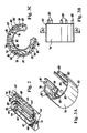
- Figs. 7 and 8 are perspective view drawings of another bearing plate to housing intermediary load structure 152.
- Bearing plate to housing intermediary load structure 54 in Figs. 1-6 was substantially one piece and monolithic.
- Bearing plate to housing intermediary load structure 152 is comprised of at least two discrete pieces 154 with spaces 158 in between pieces 154. Five pieces 154a, 154b, 154c, 154d, 154e are shown in Fig. 8 though any number of pieces could be used.
- Pieces 154 may be cylinders, spheres, flattened cylinders, pyramids, etc. An odd number of pieces may make it easier to tune bearing plate to housing intermediary load structure 152.
- Pieces 154 may be distributed around a circumference of sleeve 48, 50 so that each space 158 between each piece 154 is of the same size.
- Sleeve 48, 50 may comprise multiple pieces or a single piece.
- Each piece 154 has an internal arc with a radius of curvature 162 ( Fig. 8 ) that corresponds to or is slightly larger than a radius of curvature 160 of outer housing sleeve 48, 50.
- the inventor has discovered that the tolerance accuracy needed to manufacture monolithic bearing plate to housing intermediary load structure 52 ( Figs. 1-6 ) is quite high and therefore expensive to produce. In fact, a high percentage of manufactured pieces may need to be discarded because of the high necessary tolerances. If bearing plate to housing intermediary load structure 52 includes dimensions too far removed from defined tolerances, excess unbalanced pressure may be placed on outer housing sleeve 48, 50 and then on bearing balls 46 ( Fig. 1 ).
- bearing plate to housing intermediary load structure 152 having multiple pieces 154.
- Each piece 154 requires less tolerance accuracy which results in faster, less expensive manufacturing.
- Pieces 154 are less sensitive to twisting forces applied to outer housing sleeve 48, 50.
- Bearing plate to housing intermediary load structure 152 is less sensitive to out of "roundness" from each piece 154. Less material is used for bearing plate to housing intermediary load structure 152 and more manufacturing methods are available. Powder metal could be used to manufacture pieces 154.
- a retention member 156 (best seen in Fig. 8 ) may be used to affix bearing plate to housing intermediary load structure 152 to outer housing sleeve 48, 50.
- Retention member 156 could be, for example, a flare from each piece 154, a male extension, a female extension, etc.
- a corresponding mating retention member 164 may be disposed in outer housing sleeve 48, 50.
- Mating retention member 164 could be, for example, a recess, a female extension, a male extension, etc.
- Each piece 154 may be pliant and biased toward the position shown in the figures.
- each piece 154 may be pinched and inserted into recesses 164 of outer housing sleeve 48, 50 so that flares 156 are bent inwardly.
- the bias causes piece 154 to resume the position shown to mate with recesses 158.
- an interlock structure 170 may be formed on outer housing sleeves 48, 50 or on other sleeves used in a linear motion bearing assembly.
- One sleeve 48, 50 is shown in Fig. 9 for simplicity.
- Interlock structure 170 may be hermaphroditic including both male and female type structures.
- One interlock structure 170 may be formed on outer housing sleeve 48 and a second interlock structure 170 may be formed on outer housing sleeve 50.
- first interlock structure 170 is placed over and mates with second interlock structure 170 thereby holding linear motion bearing assembly 40 together.
- Interlock structures 170 may be placed around pieces 154a, 154b of bearing plate to housing intermediary load structure 152 discussed above so that piece 154a, 154 may be disposed in a space 176 defined by walls of interlock structure 170.
- FIG. 10 shows another structure that could be used to hold together linear motion bearing assembly 40.
- an interlock structure 180 may be formed on outer housing sleeves 48, 50 or on other sleeves used in a linear motion bearing assembly.
- Interlock structure 180 may include a tab 182, a cylindrical protrusion 184, and a recess 186.
- Tab 182 may be, for example, rectangular in cross-section.
- Outer housing sleeve 48 may include one tab 182a and outer housing sleeve 50 may include a second tab 182b.
- first interlock structure 180 is placed over second interlock structure 180, and tab 182a can be overlapped with tab 182b.
- Protrusion 184a can be placed into recess 186b and protrusion 184b can be placed into recess 186a thereby holding linear motion bearing assembly 40 together.
- Interlock structure 170 and interlock structure 180 could both be used in a single linear motion bearing assembly 40 - for example, on diametrically opposed sides.
- interlock structure 170 includes the same structure on both outer housing sleeve 48 and 50, the production of linear motion bearing assembly 40 may be simplified. Only a single type of sleeve may be produced as the sleeves are interchangeable.
- Interlock structures 170, 180 prevent linear motion bearing assembly 40 from being pulled apart due to forces extending longitudinally outward away from a center of linear motion bearing assembly 40. Locking clips 72 (discussed above with reference to Figs. 1-6 ) likely would not be able to resist such forces without interlock structures 170, 180. Interlock structures 170, 180 thus improve an integrity of linear motion bearing assembly 40.
Landscapes
- Engineering & Computer Science (AREA)
- General Engineering & Computer Science (AREA)
- Mechanical Engineering (AREA)
- Bearings For Parts Moving Linearly (AREA)
- Rolling Contact Bearings (AREA)
Applications Claiming Priority (2)
| Application Number | Priority Date | Filing Date | Title |
|---|---|---|---|
| US36455310P | 2010-07-15 | 2010-07-15 | |
| EP11741016.7A EP2593688B1 (de) | 2010-07-15 | 2011-07-15 | Linearbewegungslager mit verriegelungsstruktur |
Related Parent Applications (1)
| Application Number | Title | Priority Date | Filing Date |
|---|---|---|---|
| EP11741016.7A Division EP2593688B1 (de) | 2010-07-15 | 2011-07-15 | Linearbewegungslager mit verriegelungsstruktur |
Publications (1)
| Publication Number | Publication Date |
|---|---|
| EP3141770A1 true EP3141770A1 (de) | 2017-03-15 |
Family
ID=44511494
Family Applications (2)
| Application Number | Title | Priority Date | Filing Date |
|---|---|---|---|
| EP16188378.0A Withdrawn EP3141770A1 (de) | 2010-07-15 | 2011-07-15 | Linearbewegungslager mit verriegelungsstruktur |
| EP11741016.7A Not-in-force EP2593688B1 (de) | 2010-07-15 | 2011-07-15 | Linearbewegungslager mit verriegelungsstruktur |
Family Applications After (1)
| Application Number | Title | Priority Date | Filing Date |
|---|---|---|---|
| EP11741016.7A Not-in-force EP2593688B1 (de) | 2010-07-15 | 2011-07-15 | Linearbewegungslager mit verriegelungsstruktur |
Country Status (5)
| Country | Link |
|---|---|
| US (2) | US8979373B2 (de) |
| EP (2) | EP3141770A1 (de) |
| CN (1) | CN103140690B (de) |
| BR (1) | BR112013001043A2 (de) |
| WO (1) | WO2012009621A1 (de) |
Families Citing this family (7)
| Publication number | Priority date | Publication date | Assignee | Title |
|---|---|---|---|---|
| EP2579897A1 (de) | 2010-06-08 | 2013-04-17 | Genentech, Inc. | Cystein-manipulierte antikörper und konjugate |
| CN103154540B (zh) * | 2010-07-15 | 2015-06-24 | 托马森工业(有限)公司 | 具有带多个部件的板保持结构的直线运动轴承 |
| DE102013215619A1 (de) * | 2013-08-08 | 2015-02-12 | Schaeffler Technologies Gmbh & Co. Kg | Wälzlagerung für Turbolader und Verfahren zur Montage einer Wälzlagerung |
| JP6383553B2 (ja) * | 2014-03-28 | 2018-08-29 | 日本トムソン株式会社 | ボールスプライン |
| RU2017107502A (ru) | 2014-09-12 | 2018-10-12 | Дженентек, Инк. | Антитела и конъюгаты, сконструированные введением цистеина |
| US10935046B2 (en) | 2018-04-19 | 2021-03-02 | Raytheon Technologies Corporation | Integrally built up composite fan case |
| CN110500359B (zh) * | 2019-09-02 | 2020-10-23 | 蚌埠飞宇轴承有限公司 | 一种组合轴承 |
Citations (3)
| Publication number | Priority date | Publication date | Assignee | Title |
|---|---|---|---|---|
| US4123121A (en) * | 1975-12-19 | 1978-10-31 | Skf Industrial Trading & Development Company B.V. | Ball bearing assembly with plurality of ball guideways |
| US5346313A (en) * | 1993-07-20 | 1994-09-13 | Thomson Industries, Inc. | Linear motion bearing assembly |
| US5924745A (en) * | 1995-05-24 | 1999-07-20 | Petroline Wellsystems Limited | Connector assembly for an expandable slotted pipe |
Family Cites Families (6)
| Publication number | Priority date | Publication date | Assignee | Title |
|---|---|---|---|---|
| US4678350A (en) * | 1986-06-02 | 1987-07-07 | Statz Robert G | Bearing assembly |
| DE4038444A1 (de) * | 1990-12-01 | 1992-06-04 | Schaeffler Waelzlager Kg | Geschlitzter waelzkoerperkaefig |
| WO2000025034A1 (en) | 1998-10-27 | 2000-05-04 | Thomson Industries, Inc. | Nested track bearing |
| DE10023602C2 (de) * | 2000-05-15 | 2002-06-27 | Zf Lemfoerder Metallwaren Ag | Kugelhülsengelenk |
| JP4772381B2 (ja) * | 2004-06-03 | 2011-09-14 | Ntn株式会社 | 合成樹脂製保持器およびこの保持器を用いた玉軸受 |
| DE102004049069B4 (de) | 2004-10-08 | 2009-01-02 | Ab Skf | Verbinder und Lager für eine Längsbewegung mit dem Verbinder |
-
2011
- 2011-07-15 US US13/810,239 patent/US8979373B2/en active Active
- 2011-07-15 EP EP16188378.0A patent/EP3141770A1/de not_active Withdrawn
- 2011-07-15 CN CN201180034916.3A patent/CN103140690B/zh not_active Expired - Fee Related
- 2011-07-15 EP EP11741016.7A patent/EP2593688B1/de not_active Not-in-force
- 2011-07-15 BR BR112013001043A patent/BR112013001043A2/pt not_active Application Discontinuation
- 2011-07-15 WO PCT/US2011/044158 patent/WO2012009621A1/en active Application Filing
-
2015
- 2015-02-17 US US14/623,735 patent/US20150226257A1/en not_active Abandoned
Patent Citations (3)
| Publication number | Priority date | Publication date | Assignee | Title |
|---|---|---|---|---|
| US4123121A (en) * | 1975-12-19 | 1978-10-31 | Skf Industrial Trading & Development Company B.V. | Ball bearing assembly with plurality of ball guideways |
| US5346313A (en) * | 1993-07-20 | 1994-09-13 | Thomson Industries, Inc. | Linear motion bearing assembly |
| US5924745A (en) * | 1995-05-24 | 1999-07-20 | Petroline Wellsystems Limited | Connector assembly for an expandable slotted pipe |
Also Published As
| Publication number | Publication date |
|---|---|
| EP2593688B1 (de) | 2016-09-14 |
| US20130209008A1 (en) | 2013-08-15 |
| US20150226257A1 (en) | 2015-08-13 |
| CN103140690B (zh) | 2016-07-06 |
| BR112013001043A2 (pt) | 2016-05-24 |
| US8979373B2 (en) | 2015-03-17 |
| EP2593688A1 (de) | 2013-05-22 |
| WO2012009621A1 (en) | 2012-01-19 |
| CN103140690A (zh) | 2013-06-05 |
Similar Documents
| Publication | Publication Date | Title |
|---|---|---|
| EP2593688B1 (de) | Linearbewegungslager mit verriegelungsstruktur | |
| US9512877B2 (en) | Linear motion bearing with improved outer housing sleeve | |
| US6261005B1 (en) | Rolling bearing cage | |
| US6409387B1 (en) | Ball bushing | |
| US20070160313A1 (en) | Ball Chain | |
| US20180010637A1 (en) | Rolling bearing | |
| EP3164613B1 (de) | Wälzlagerkäfig | |
| US20160108956A1 (en) | Linear motion bearing system with self-aligning rail | |
| CN104334898A (zh) | 外筒被分割成三部分的直线运动轴承 | |
| EP2593687B1 (de) | Linearbewegungslager mit einer plattenhaltestruktur mit mehreren teilen | |
| EP1158190B1 (de) | Linearlager | |
| EP3135931A1 (de) | Zweischalige lageranordnung mit linearbewegung | |
| CN108884865B (zh) | 多列圆筒滚子轴承 | |
| JP5194551B2 (ja) | 軸受用クリープ防止機構 | |
| US9689426B2 (en) | Linear motion bearing with modular bearing segments | |
| US9638249B2 (en) | Bearing cage with resilient inserts between pockets | |
| JP5488938B2 (ja) | 軸受用クリープ防止機構 | |
| CN108884866B (zh) | 组合式圆筒滚子轴承 | |
| EP3250835A1 (de) | Linearbewegungslageranordnung mit modularen lagersegmenten |
Legal Events
| Date | Code | Title | Description |
|---|---|---|---|
| PUAI | Public reference made under article 153(3) epc to a published international application that has entered the european phase |
Free format text: ORIGINAL CODE: 0009012 |
|
| AC | Divisional application: reference to earlier application |
Ref document number: 2593688 Country of ref document: EP Kind code of ref document: P |
|
| AK | Designated contracting states |
Kind code of ref document: A1 Designated state(s): AL AT BE BG CH CY CZ DE DK EE ES FI FR GB GR HR HU IE IS IT LI LT LU LV MC MK MT NL NO PL PT RO RS SE SI SK SM TR |
|
| AX | Request for extension of the european patent |
Extension state: BA ME |
|
| STAA | Information on the status of an ep patent application or granted ep patent |
Free format text: STATUS: THE APPLICATION IS DEEMED TO BE WITHDRAWN |
|
| 18D | Application deemed to be withdrawn |
Effective date: 20170916 |