EP3141492A1 - Conteneur comprenant une porte rabatable ayant un mécanisme d'attache à axes multiples - Google Patents
Conteneur comprenant une porte rabatable ayant un mécanisme d'attache à axes multiples Download PDFInfo
- Publication number
- EP3141492A1 EP3141492A1 EP16187744.4A EP16187744A EP3141492A1 EP 3141492 A1 EP3141492 A1 EP 3141492A1 EP 16187744 A EP16187744 A EP 16187744A EP 3141492 A1 EP3141492 A1 EP 3141492A1
- Authority
- EP
- European Patent Office
- Prior art keywords
- door
- axis
- container
- rotation
- hinge
- Prior art date
- Legal status (The legal status is an assumption and is not a legal conclusion. Google has not performed a legal analysis and makes no representation as to the accuracy of the status listed.)
- Granted
Links
- 239000012815 thermoplastic material Substances 0.000 claims description 4
- 125000006850 spacer group Chemical group 0.000 description 6
- -1 for example Substances 0.000 description 3
- 230000007704 transition Effects 0.000 description 3
- 238000000034 method Methods 0.000 description 2
- 238000012986 modification Methods 0.000 description 2
- 230000004048 modification Effects 0.000 description 2
- 239000004698 Polyethylene Substances 0.000 description 1
- 239000004743 Polypropylene Substances 0.000 description 1
- 239000004676 acrylonitrile butadiene styrene Substances 0.000 description 1
- 230000008859 change Effects 0.000 description 1
- 238000009434 installation Methods 0.000 description 1
- 238000005259 measurement Methods 0.000 description 1
- 230000007246 mechanism Effects 0.000 description 1
- 229920000515 polycarbonate Polymers 0.000 description 1
- 239000004417 polycarbonate Substances 0.000 description 1
- 229920000573 polyethylene Polymers 0.000 description 1
- 229920000642 polymer Polymers 0.000 description 1
- 229920001155 polypropylene Polymers 0.000 description 1
- 230000008569 process Effects 0.000 description 1
- 238000000926 separation method Methods 0.000 description 1
Images


Classifications
-
- E—FIXED CONSTRUCTIONS
- E05—LOCKS; KEYS; WINDOW OR DOOR FITTINGS; SAFES
- E05D—HINGES OR SUSPENSION DEVICES FOR DOORS, WINDOWS OR WINGS
- E05D15/00—Suspension arrangements for wings
- E05D15/48—Suspension arrangements for wings allowing alternative movements
-
- B—PERFORMING OPERATIONS; TRANSPORTING
- B65—CONVEYING; PACKING; STORING; HANDLING THIN OR FILAMENTARY MATERIAL
- B65D—CONTAINERS FOR STORAGE OR TRANSPORT OF ARTICLES OR MATERIALS, e.g. BAGS, BARRELS, BOTTLES, BOXES, CANS, CARTONS, CRATES, DRUMS, JARS, TANKS, HOPPERS, FORWARDING CONTAINERS; ACCESSORIES, CLOSURES, OR FITTINGS THEREFOR; PACKAGING ELEMENTS; PACKAGES
- B65D19/00—Pallets or like platforms, with or without side walls, for supporting loads to be lifted or lowered
- B65D19/02—Rigid pallets with side walls, e.g. box pallets
- B65D19/06—Rigid pallets with side walls, e.g. box pallets with bodies formed by uniting or interconnecting two or more components
- B65D19/18—Rigid pallets with side walls, e.g. box pallets with bodies formed by uniting or interconnecting two or more components made wholly or mainly of plastics material
-
- B—PERFORMING OPERATIONS; TRANSPORTING
- B65—CONVEYING; PACKING; STORING; HANDLING THIN OR FILAMENTARY MATERIAL
- B65D—CONTAINERS FOR STORAGE OR TRANSPORT OF ARTICLES OR MATERIALS, e.g. BAGS, BARRELS, BOTTLES, BOXES, CANS, CARTONS, CRATES, DRUMS, JARS, TANKS, HOPPERS, FORWARDING CONTAINERS; ACCESSORIES, CLOSURES, OR FITTINGS THEREFOR; PACKAGING ELEMENTS; PACKAGES
- B65D19/00—Pallets or like platforms, with or without side walls, for supporting loads to be lifted or lowered
- B65D19/38—Details or accessories
-
- B—PERFORMING OPERATIONS; TRANSPORTING
- B65—CONVEYING; PACKING; STORING; HANDLING THIN OR FILAMENTARY MATERIAL
- B65D—CONTAINERS FOR STORAGE OR TRANSPORT OF ARTICLES OR MATERIALS, e.g. BAGS, BARRELS, BOTTLES, BOXES, CANS, CARTONS, CRATES, DRUMS, JARS, TANKS, HOPPERS, FORWARDING CONTAINERS; ACCESSORIES, CLOSURES, OR FITTINGS THEREFOR; PACKAGING ELEMENTS; PACKAGES
- B65D25/00—Details of other kinds or types of rigid or semi-rigid containers
- B65D25/005—Side walls formed with an aperture or a movable portion arranged to allow removal or insertion of contents
-
- E—FIXED CONSTRUCTIONS
- E05—LOCKS; KEYS; WINDOW OR DOOR FITTINGS; SAFES
- E05D—HINGES OR SUSPENSION DEVICES FOR DOORS, WINDOWS OR WINGS
- E05D3/00—Hinges with pins
- E05D3/02—Hinges with pins with one pin
-
- E—FIXED CONSTRUCTIONS
- E06—DOORS, WINDOWS, SHUTTERS, OR ROLLER BLINDS IN GENERAL; LADDERS
- E06B—FIXED OR MOVABLE CLOSURES FOR OPENINGS IN BUILDINGS, VEHICLES, FENCES OR LIKE ENCLOSURES IN GENERAL, e.g. DOORS, WINDOWS, BLINDS, GATES
- E06B5/00—Doors, windows, or like closures for special purposes; Border constructions therefor
-
- B—PERFORMING OPERATIONS; TRANSPORTING
- B65—CONVEYING; PACKING; STORING; HANDLING THIN OR FILAMENTARY MATERIAL
- B65D—CONTAINERS FOR STORAGE OR TRANSPORT OF ARTICLES OR MATERIALS, e.g. BAGS, BARRELS, BOTTLES, BOXES, CANS, CARTONS, CRATES, DRUMS, JARS, TANKS, HOPPERS, FORWARDING CONTAINERS; ACCESSORIES, CLOSURES, OR FITTINGS THEREFOR; PACKAGING ELEMENTS; PACKAGES
- B65D2519/00—Pallets or like platforms, with or without side walls, for supporting loads to be lifted or lowered
- B65D2519/00004—Details relating to pallets
- B65D2519/00009—Materials
- B65D2519/00014—Materials for the load supporting surface
- B65D2519/00034—Plastic
-
- B—PERFORMING OPERATIONS; TRANSPORTING
- B65—CONVEYING; PACKING; STORING; HANDLING THIN OR FILAMENTARY MATERIAL
- B65D—CONTAINERS FOR STORAGE OR TRANSPORT OF ARTICLES OR MATERIALS, e.g. BAGS, BARRELS, BOTTLES, BOXES, CANS, CARTONS, CRATES, DRUMS, JARS, TANKS, HOPPERS, FORWARDING CONTAINERS; ACCESSORIES, CLOSURES, OR FITTINGS THEREFOR; PACKAGING ELEMENTS; PACKAGES
- B65D2519/00—Pallets or like platforms, with or without side walls, for supporting loads to be lifted or lowered
- B65D2519/00004—Details relating to pallets
- B65D2519/00009—Materials
- B65D2519/00049—Materials for the base surface
- B65D2519/00069—Plastic
-
- B—PERFORMING OPERATIONS; TRANSPORTING
- B65—CONVEYING; PACKING; STORING; HANDLING THIN OR FILAMENTARY MATERIAL
- B65D—CONTAINERS FOR STORAGE OR TRANSPORT OF ARTICLES OR MATERIALS, e.g. BAGS, BARRELS, BOTTLES, BOXES, CANS, CARTONS, CRATES, DRUMS, JARS, TANKS, HOPPERS, FORWARDING CONTAINERS; ACCESSORIES, CLOSURES, OR FITTINGS THEREFOR; PACKAGING ELEMENTS; PACKAGES
- B65D2519/00—Pallets or like platforms, with or without side walls, for supporting loads to be lifted or lowered
- B65D2519/00004—Details relating to pallets
- B65D2519/00009—Materials
- B65D2519/00154—Materials for the side walls
- B65D2519/00174—Plastic
-
- B—PERFORMING OPERATIONS; TRANSPORTING
- B65—CONVEYING; PACKING; STORING; HANDLING THIN OR FILAMENTARY MATERIAL
- B65D—CONTAINERS FOR STORAGE OR TRANSPORT OF ARTICLES OR MATERIALS, e.g. BAGS, BARRELS, BOTTLES, BOXES, CANS, CARTONS, CRATES, DRUMS, JARS, TANKS, HOPPERS, FORWARDING CONTAINERS; ACCESSORIES, CLOSURES, OR FITTINGS THEREFOR; PACKAGING ELEMENTS; PACKAGES
- B65D2519/00—Pallets or like platforms, with or without side walls, for supporting loads to be lifted or lowered
- B65D2519/00004—Details relating to pallets
- B65D2519/00258—Overall construction
- B65D2519/00263—Overall construction of the pallet
- B65D2519/00273—Overall construction of the pallet made of more than one piece
-
- B—PERFORMING OPERATIONS; TRANSPORTING
- B65—CONVEYING; PACKING; STORING; HANDLING THIN OR FILAMENTARY MATERIAL
- B65D—CONTAINERS FOR STORAGE OR TRANSPORT OF ARTICLES OR MATERIALS, e.g. BAGS, BARRELS, BOTTLES, BOXES, CANS, CARTONS, CRATES, DRUMS, JARS, TANKS, HOPPERS, FORWARDING CONTAINERS; ACCESSORIES, CLOSURES, OR FITTINGS THEREFOR; PACKAGING ELEMENTS; PACKAGES
- B65D2519/00—Pallets or like platforms, with or without side walls, for supporting loads to be lifted or lowered
- B65D2519/00004—Details relating to pallets
- B65D2519/00258—Overall construction
- B65D2519/00283—Overall construction of the load supporting surface
- B65D2519/00293—Overall construction of the load supporting surface made of more than one piece
-
- B—PERFORMING OPERATIONS; TRANSPORTING
- B65—CONVEYING; PACKING; STORING; HANDLING THIN OR FILAMENTARY MATERIAL
- B65D—CONTAINERS FOR STORAGE OR TRANSPORT OF ARTICLES OR MATERIALS, e.g. BAGS, BARRELS, BOTTLES, BOXES, CANS, CARTONS, CRATES, DRUMS, JARS, TANKS, HOPPERS, FORWARDING CONTAINERS; ACCESSORIES, CLOSURES, OR FITTINGS THEREFOR; PACKAGING ELEMENTS; PACKAGES
- B65D2519/00—Pallets or like platforms, with or without side walls, for supporting loads to be lifted or lowered
- B65D2519/00004—Details relating to pallets
- B65D2519/00258—Overall construction
- B65D2519/00313—Overall construction of the base surface
- B65D2519/00323—Overall construction of the base surface made of more than one piece
-
- B—PERFORMING OPERATIONS; TRANSPORTING
- B65—CONVEYING; PACKING; STORING; HANDLING THIN OR FILAMENTARY MATERIAL
- B65D—CONTAINERS FOR STORAGE OR TRANSPORT OF ARTICLES OR MATERIALS, e.g. BAGS, BARRELS, BOTTLES, BOXES, CANS, CARTONS, CRATES, DRUMS, JARS, TANKS, HOPPERS, FORWARDING CONTAINERS; ACCESSORIES, CLOSURES, OR FITTINGS THEREFOR; PACKAGING ELEMENTS; PACKAGES
- B65D2519/00—Pallets or like platforms, with or without side walls, for supporting loads to be lifted or lowered
- B65D2519/00004—Details relating to pallets
- B65D2519/00258—Overall construction
- B65D2519/00313—Overall construction of the base surface
- B65D2519/00328—Overall construction of the base surface shape of the contact surface of the base
- B65D2519/00338—Overall construction of the base surface shape of the contact surface of the base contact surface having a discrete foot-like shape
-
- B—PERFORMING OPERATIONS; TRANSPORTING
- B65—CONVEYING; PACKING; STORING; HANDLING THIN OR FILAMENTARY MATERIAL
- B65D—CONTAINERS FOR STORAGE OR TRANSPORT OF ARTICLES OR MATERIALS, e.g. BAGS, BARRELS, BOTTLES, BOXES, CANS, CARTONS, CRATES, DRUMS, JARS, TANKS, HOPPERS, FORWARDING CONTAINERS; ACCESSORIES, CLOSURES, OR FITTINGS THEREFOR; PACKAGING ELEMENTS; PACKAGES
- B65D2519/00—Pallets or like platforms, with or without side walls, for supporting loads to be lifted or lowered
- B65D2519/00004—Details relating to pallets
- B65D2519/00258—Overall construction
- B65D2519/00492—Overall construction of the side walls
- B65D2519/00497—Overall construction of the side walls whereby at least one side wall is made of one piece
-
- B—PERFORMING OPERATIONS; TRANSPORTING
- B65—CONVEYING; PACKING; STORING; HANDLING THIN OR FILAMENTARY MATERIAL
- B65D—CONTAINERS FOR STORAGE OR TRANSPORT OF ARTICLES OR MATERIALS, e.g. BAGS, BARRELS, BOTTLES, BOXES, CANS, CARTONS, CRATES, DRUMS, JARS, TANKS, HOPPERS, FORWARDING CONTAINERS; ACCESSORIES, CLOSURES, OR FITTINGS THEREFOR; PACKAGING ELEMENTS; PACKAGES
- B65D2519/00—Pallets or like platforms, with or without side walls, for supporting loads to be lifted or lowered
- B65D2519/00004—Details relating to pallets
- B65D2519/00258—Overall construction
- B65D2519/00492—Overall construction of the side walls
- B65D2519/00502—Overall construction of the side walls whereby at least one side wall is made of two or more pieces
-
- B—PERFORMING OPERATIONS; TRANSPORTING
- B65—CONVEYING; PACKING; STORING; HANDLING THIN OR FILAMENTARY MATERIAL
- B65D—CONTAINERS FOR STORAGE OR TRANSPORT OF ARTICLES OR MATERIALS, e.g. BAGS, BARRELS, BOTTLES, BOXES, CANS, CARTONS, CRATES, DRUMS, JARS, TANKS, HOPPERS, FORWARDING CONTAINERS; ACCESSORIES, CLOSURES, OR FITTINGS THEREFOR; PACKAGING ELEMENTS; PACKAGES
- B65D2519/00—Pallets or like platforms, with or without side walls, for supporting loads to be lifted or lowered
- B65D2519/00004—Details relating to pallets
- B65D2519/00547—Connections
- B65D2519/00577—Connections structures connecting side walls, including corner posts, to each other
- B65D2519/00582—Connections structures connecting side walls, including corner posts, to each other structures intended to be disassembled, i.e. collapsible or dismountable
- B65D2519/00611—Connections structures connecting side walls, including corner posts, to each other structures intended to be disassembled, i.e. collapsible or dismountable side walls maintained connected to each other by means of auxiliary locking elements, e.g. spring loaded locking pins
-
- B—PERFORMING OPERATIONS; TRANSPORTING
- B65—CONVEYING; PACKING; STORING; HANDLING THIN OR FILAMENTARY MATERIAL
- B65D—CONTAINERS FOR STORAGE OR TRANSPORT OF ARTICLES OR MATERIALS, e.g. BAGS, BARRELS, BOTTLES, BOXES, CANS, CARTONS, CRATES, DRUMS, JARS, TANKS, HOPPERS, FORWARDING CONTAINERS; ACCESSORIES, CLOSURES, OR FITTINGS THEREFOR; PACKAGING ELEMENTS; PACKAGES
- B65D2519/00—Pallets or like platforms, with or without side walls, for supporting loads to be lifted or lowered
- B65D2519/00004—Details relating to pallets
- B65D2519/00547—Connections
- B65D2519/00636—Connections structures connecting side walls to the pallet
- B65D2519/00641—Structures intended to be disassembled
- B65D2519/00646—Structures intended to be disassembled by means of hinges
-
- B—PERFORMING OPERATIONS; TRANSPORTING
- B65—CONVEYING; PACKING; STORING; HANDLING THIN OR FILAMENTARY MATERIAL
- B65D—CONTAINERS FOR STORAGE OR TRANSPORT OF ARTICLES OR MATERIALS, e.g. BAGS, BARRELS, BOTTLES, BOXES, CANS, CARTONS, CRATES, DRUMS, JARS, TANKS, HOPPERS, FORWARDING CONTAINERS; ACCESSORIES, CLOSURES, OR FITTINGS THEREFOR; PACKAGING ELEMENTS; PACKAGES
- B65D2519/00—Pallets or like platforms, with or without side walls, for supporting loads to be lifted or lowered
- B65D2519/00004—Details relating to pallets
- B65D2519/00736—Details
- B65D2519/00805—Means for facilitating the removal of the load
-
- B—PERFORMING OPERATIONS; TRANSPORTING
- B65—CONVEYING; PACKING; STORING; HANDLING THIN OR FILAMENTARY MATERIAL
- B65D—CONTAINERS FOR STORAGE OR TRANSPORT OF ARTICLES OR MATERIALS, e.g. BAGS, BARRELS, BOTTLES, BOXES, CANS, CARTONS, CRATES, DRUMS, JARS, TANKS, HOPPERS, FORWARDING CONTAINERS; ACCESSORIES, CLOSURES, OR FITTINGS THEREFOR; PACKAGING ELEMENTS; PACKAGES
- B65D2519/00—Pallets or like platforms, with or without side walls, for supporting loads to be lifted or lowered
- B65D2519/00004—Details relating to pallets
- B65D2519/00736—Details
- B65D2519/00865—Collapsible, i.e. at least two constitutive elements remaining hingedly connected
- B65D2519/00875—Collapsible, i.e. at least two constitutive elements remaining hingedly connected collapsible side walls
- B65D2519/009—Collapsible, i.e. at least two constitutive elements remaining hingedly connected collapsible side walls whereby all side walls are hingedly connected to the base panel
-
- E—FIXED CONSTRUCTIONS
- E05—LOCKS; KEYS; WINDOW OR DOOR FITTINGS; SAFES
- E05D—HINGES OR SUSPENSION DEVICES FOR DOORS, WINDOWS OR WINGS
- E05D15/00—Suspension arrangements for wings
- E05D15/48—Suspension arrangements for wings allowing alternative movements
- E05D2015/485—Swinging or sliding movements
-
- E—FIXED CONSTRUCTIONS
- E05—LOCKS; KEYS; WINDOW OR DOOR FITTINGS; SAFES
- E05Y—INDEXING SCHEME ASSOCIATED WITH SUBCLASSES E05D AND E05F, RELATING TO CONSTRUCTION ELEMENTS, ELECTRIC CONTROL, POWER SUPPLY, POWER SIGNAL OR TRANSMISSION, USER INTERFACES, MOUNTING OR COUPLING, DETAILS, ACCESSORIES, AUXILIARY OPERATIONS NOT OTHERWISE PROVIDED FOR, APPLICATION THEREOF
- E05Y2999/00—Subject-matter not otherwise provided for in this subclass
Definitions
- the present specification generally relates to hinges for opening doors in a container and, more specifically, to hinges that provide multiple axes of rotation for a door of a shipping container.
- Containers can be utilized to assist with transporting and storing goods of various size, weight, and composition.
- a container can be provided as a box that provides a top opening for loading goods into the box.
- the container can include a lower interface for handling by a transport device.
- Typical transport devices can include forklifts, pallet jacks, front loaders, or the like.
- Some containers can be provided with drop down doors to facilitate the loading of goods into a container by expanding the size of the top opening.
- Some containers include locking features that secure the door to the container.
- locking features can be complex and make the door inefficient to open. Further, such locking features may alter the opening geometry and prevent the door from fully opening. The door can thus create an obstruction that makes the container more difficult to load and reduces the efficacy of the door.
- a multi-axis hinge can include a fixed axis body and an articulating body.
- the fixed axis body and the articulating body can be in rotational engagement and can be configured to rotate with respect to one another around a hinge rotational axis.
- the fixed axis body can include a first pillar and a second pillar that extends away from the hinge rotational axis.
- the first pillar and the second pillar can each include a panel engagement member.
- the articulating body can include a first articulating pillar and a second articulating pillar that extends away from the hinge rotational axis.
- the first articulating pillar and the second articulating pillar can each include a door engagement member.
- a container can include a multi-axis hinge, an access panel, and a door.
- the multi-axis hinge can include a fixed axis body and an articulating body.
- the fixed axis body and the articulating body can be in rotational engagement and can be configured to rotate with respect to one another around a hinge rotational axis.
- the access panel can comprise a doorway that forms a recess that extends from an upper perimeter of the container towards a base of the container.
- the fixed axis body of the multi-axis hinge can be in rotational engagement with the access panel.
- the door can be configured to selectively close and open with respect to the doorway.
- the articulating body of the multi-axis hinge can form a rotational and sliding engagement with the door.
- a container can include a multi-axis hinge, an access panel, and a door.
- the multi-axis hinge can include a fixed axis body and an articulating body.
- the fixed axis body and the articulating body can be in rotational engagement and can be configured to rotate with respect to one another around a hinge rotational axis.
- the access panel can comprise a doorway that forms a recess that extends from an upper perimeter of the container towards a base of the container.
- the fixed axis body of the multi-axis hinge can be in rotational engagement with the access panel to define a fixed axis of rotation.
- the door can be configured to selectively close and open with respect to the doorway.
- the articulating body of the multi-axis hinge can form a rotational and sliding engagement with the door to define a sliding rotational axis.
- the access panel can include one or more pocket members formed adjacent to the doorway, and the door can include one or more peg members configured to selectively lock with the pocket members of the access panel. Rotation of the door around the fixed axis of rotation can be mitigated, when the one or more peg members are locked with the one or more pocket members.
- the door can translate with respect to the sliding rotational axis between a first state and a second state.
- the door When in the first state, the door can enclose the doorway, and rotation of the door around the fixed axis of rotation can be mitigated.
- the door When in the second state, the door can enclose the doorway, and rotation of the door around the fixed axis of rotation can be permitted.
- the access panel can include an inner bounding feature that delimits the motion of the door with respect to the fixed axis of rotation.
- the multi-axis hinge can rotate with respect to the fixed axis of rotation, the hinge rotational axis, and the sliding rotational axis between the second state and an additional state.
- an exterior surface of the door can contact an exterior surface of the access panel.
- the door lays flat with respect to the access panel.
- the multi-axis hinge can include a stop feature that sets a predetermined angle between the fixed axis body and the articulating body with respect to the hinge rotational axis.
- the predetermined angle can be between 75° and 105°.
- the fixed axis body can include a pillar extending from the hinge rotational axis towards the fixed axis of rotation and including a panel engagement member.
- the panel engagement member can be in rotational engagement with the access panel along the fixed axis of rotation.
- the panel engagement member can include a substantially cylindrical pillar extending along the fixed axis of rotation.
- the panel engagement member can include a cylindrical bore formed along the fixed axis of rotation.
- the fixed axis body can include an articulating pillar extending from the hinge rotational axis towards the sliding rotational axis and including a door engagement member.
- the door engagement member can be in rotational and sliding engagement with the door.
- the door engagement member can include a substantially cylindrical pillar extending along the sliding rotational axis.
- the door engagement member can include an elongate slot.
- any of the multi-axis hinges and containers provided herein can include or be formed from a thermoplastic material.
- a cantilevered detent can extend from one or more of a first pillar of the fixed axis body, a second pillar of the fixed axis body, a first articulating pillar of the articulating body, and a second articulating pillar of the articulating body.
- the first pillar of the fixed axis body, the second pillar of the fixed axis body, the first articulating pillar of the articulating body, and the second articulating pillar of the articulating body can form an "H" shape.
- the fixed axis body and the articulating body can each include an angled face that bounds the motion of the fixed axis body and the articulating body around the hinge rotational axis at a predetermined angle.
- the predetermined angle can be between 75° and 105°.
- the first pillar of the fixed axis body can extend a shorter length than the first articulating pillar.
- a container comprising: an access panel that defines a doorway that forms a recess extending from an upper perimeter of the container towards a base of the container; a door configured to selectively close and open with respect to the doorway; and a multi-axis hinge comprising a fixed access body in rotational engagement with an articulating body, wherein: the fixed access body and the articulating body rotate with respect to one another around a hinge rotational axis; the fixed axis body is in rotational engagement with the access panel to define a fixed axis of rotation; and the articulating body of the multi-axis hinge is in rotational and sliding engagement with the door to define a sliding rotational axis.
- the access panel comprises one or more pocket members formed adjacent to the doorway;
- the door comprises one or more peg members configured to selectively lock with the pocket members of the access panel; and rotation of the door around the fixed axis of rotation is mitigated, when the one or more peg members are locked with the one or more pocket members.
- the door translates with respect to the sliding rotational axis between a first state and a second state; when in the first state, the door encloses the doorway, and rotation of the door around the fixed axis of rotation is mitigated; and when in the second state, the door encloses the doorway, and rotation of the door around the fixed axis of rotation is permitted.
- the access panel comprises an inner bounding feature that delimits the motion of the door with respect to the fixed axis of rotation.
- the multi-axis hinge rotates with respect to the fixed axis of rotation, the hinge rotational axis, and the sliding rotational axis between the second state and an additional state; and when in the additional state, the door lays flat with respect to the access panel.
- multi-axis hinge comprises a stop feature that sets a predetermined angle between the fixed axis body and the articulating body with respect to the hinge rotational axis.
- the predetermined angle is between 75° and 105°.
- the fixed axis body comprises a pillar extending from the hinge rotational axis towards the fixed axis of rotation and comprising a panel engagement member, wherein the panel engagement member is in rotational engagement with the access panel along the fixed axis of rotation.
- the panel engagement member comprises a substantially cylindrical pillar extending along the fixed axis of rotation.
- the panel engagement member comprises a cylindrical bore formed along the fixed axis of rotation.
- the fixed axis body comprises an articulating pillar extending from the hinge rotational axis towards the sliding rotational axis and comprising a door engagement member, wherein the door engagement member is in rotational and sliding engagement with the door.
- the door engagement member comprises a substantially cylindrical pillar extending along the sliding rotational axis.
- the door engagement member comprises an elongate slot.
- the container comprises thermoplastic material.
- the present invention also provides a multi-axis hinge comprising: a fixed axis body comprising a first pillar and a second pillar extending away from a hinge rotational axis, wherein the first pillar and the second pillar each include a panel engagement member; and an articulating body in rotational engagement with the fixed axis body along the hinge rotational axis, wherein the articulating body comprises a first articulating pillar and a second articulating pillar that extend away from the hinge rotational axis, and wherein the first articulating pillar and the second articulating pillar each include a door engagement member.
- the multi-axis hinge comprises a cantilevered detent extending from one or more of the first pillar of the fixed axis body, the second pillar of the fixed axis body, the first articulating pillar of the articulating body, and the second articulating pillar of the articulating body.
- the first pillar of the fixed axis body, the second pillar of the fixed axis body, the first articulating pillar of the articulating body, and the second articulating pillar of the articulating body form an "H" shape.
- the fixed axis body and the articulating body each comprises an angled face that bounds the motion of the fixed axis body and the articulating body around the hinge rotational axis at a predetermined angle, and wherein the predetermined angle is between 75° and 105°.
- the first pillar of the fixed axis body extends a shorter length than the first articulating pillar.
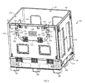
- the container 100 can be formed from thermoplastic material such as, for example, Acrylonitrile butadiene styrene (ABS), Polycarbonate, Polyethylene, Polypropylene, or any other heat moldable polymer.
- the container 100 can be configured to store and at least partially enclose goods.
- the container 100 can comprise a plurality of walls 102 that extend vertically from a base 104 to an upper perimeter 106 that forms an enclosure.
- the plurality of walls 102 and the base 104 can form a substantially rectangular shaped upper perimeter 106.
- the upper perimeter 106 can bound an opening that can be used to access the enclosure.
- the container 100 can furthermore be configured to be loaded and unloaded with devices such as, for example, a forklift, hand pallet truck, or the like. Accordingly, the container 100 can comprise feet 108 that raise the container 100 with respect to a work surface. The feet 108 can be offset to allow the forks of a forklift to be received beneath the base 104 of the container 100 and the work surface.
- one or more of the walls 102 can be provided as an access panel 110 that is configured to provide additional access to the enclosure formed by the container 100.
- the access panel 110 can comprise a doorway 112 that is formed through the access panel 110.
- the doorway 112 can form a recess that extends from the upper perimeter 106 of the container 100 towards the base 104 of the container 100. Accordingly, the enclosure can be accessed at a relatively lower height with respect to a work surface through the doorway 112 compared to the upper perimeter 106.
- the doorway 112 can be substantially rectangular shaped. Alternatively or additionally, the doorway 112 can comprise beveled corners.
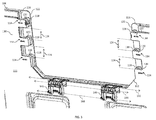
- the access panel 110 can comprise one or more pocket members 114 configured to selectively prevent motion of a door 130 with respect to a fixed axis of rotation 132.
- the pocket member 114 can form a cavity adjacent to the doorway 112.
- each pocket member 114 can form a cavity along a transitional feature 116 that is positioned along the access panel 110 adjacent to the doorway 112.
- the pocket member 114 can comprise a spacer 118 offset from the transitional feature 116 such that the spacer is nearer to the doorway 112 than the transitional feature 116.
- the pocket member 114 can further comprise an outer bounding feature 120 that spans the distance between the transitional feature 116 and the spacer 118.
- the outer bounding feature 120 can be thinner than the transitional feature 116 and the spacer 118. Accordingly, a cavity can be formed by the transitional feature 116, the spacer 118, and the outer bounding feature 120.
- the access panel 110 can comprise an inner bounding feature 122 configured to delimit the motion of the door 130 with respect to the fixed axis of rotation 132.
- the inner bounding feature 122 can extend from the doorway 112 towards the transitional feature 116.
- the inner bounding feature 122 can be offset from the outer bounding feature 120 by the spacer 118. Accordingly, the cavity can be located between the outer bounding feature 120 and the inner bounding feature 122.
- the pocket members 114 can be arranged in a substantially serrated pattern.
- the pocket members 114 can be aligned in a substantially linear column and separated from one another.
- Each outer bounding feature 120 can form projections having a span 124 there between.
- the inner bounding feature 122 can be larger than the outer bounding feature 120. Accordingly, the inner bounding feature 122 can at least partially cover the span 124 between each of the pocket members 114.
- the container 100 can comprise a door 130 that is configured to selectively close ( FIG. 1 ) and open ( FIG. 2 ) the door 130 with respect to the doorway 112.
- the door 130 can be a body that is correspondingly shaped to the doorway 112 of the container 100.
- the door 130 can comprise one or more peg members 133 that are configured to selectively lock with the pocket members 114 of the access panel 110.
- the peg members 133 can comprise a projecting member 134 that extends away from the door 130 and a locking member 136 that extends away from the projecting member 134.
- the projecting member 134 can be cantilevered from the door 130.
- the locking member 136 can extend away from a distal end of the projecting member 134 such that the locking member 136 is offset from the door 130.
- the locking member 136 and the projecting member 134 can form a substantially "L" shaped body.
- the locking member 136 can be configured to engage with the pocket member 114 of the doorway 112. Accordingly, the locking member 136 can be shaped to fit within the cavity bounded by the pocket member 114, i.e., the locking member 136 can be correspondingly shaped to the cavity. Alternatively or additionally, the locking member 136 can extend from the projecting member 134 towards the pocket member 114, when the door 130 is in the closed position. For example, when the door 130 is in the closed position, the locking member 136 can extend substantially downwards from the projecting member 134.
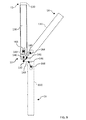
- the container 100 can comprise a multi-axis hinge 140 that is configured to facilitate articulation of the door 130 with respect to the doorway 112.
- the multi-axis hinge 140 can comprise a fixed axis body 142 in rotational engagement with an articulating body 144.
- the fixed axis body 142 and the articulating body 144 can be configured to rotate with respect to one another around a hinge rotational axis 146.
- the fixed axis body 142 can comprise a first joint member 148 and the articulating body 144 can comprise a second joint member 150.
- the first joint member 148 and the second joint member 150 can form a plurality of correspondingly shaped knuckles that can be in rotational engagement and configured to rotate with respect to one another around the hinge rotational axis 146.
- the plurality of correspondingly shaped knuckles of the first joint member 148 and the second joint member 150 can receive a pin.
- the pin can be aligned with the hinge rotational axis 146 such that the knuckles form a serrated joint that permits rotation of the fixed axis body 142 and the articulating body 144.
- the plurality of correspondingly shaped knuckles of the first joint member 148 and the second joint member 150 can interlock (e.g., snap fit), without a pin, to form the rotational engagement.
- the multi-axis hinge 140 can comprise a stop feature 152 configured to set a predetermined angle 154 between the fixed axis body 142 and the articulating body 144 with respect to the hinge rotational axis 146.
- the first joint member 148, the second joint member 150, or both can comprise an angled face 156 positioned adjacent to the hinge rotational axis 146.
- each of the first joint member 148 and the second joint member 150 can comprise an angled face 156 that bounds the motion of the fixed axis body 142 and the articulating body 144 around the hinge rotational axis 146.
- the predetermined angle 154 can be between about 75° and about 105° such as, for example, between about 80° and about 100° in one embodiment, or between about 80° and about 95°.
- the fixed axis body 142 can comprise a first pillar 158 and a second pillar 160 configured to offset the hinge rotational axis 146 from the fixed axis of rotation 132.
- each of the first pillar 158 and the second pillar 160 can be an elongate body that extends away from the first joint member 148 of the fixed axis body 142.
- the first pillar 158 and the second pillar 160 can be offset from one another along the fixed axis of rotation 132.
- the first pillar 158 and the second pillar 160 can be substantially parallel.
- Each of the first pillar 158 and the second pillar 160 can comprise a panel engagement member 162 that is configured to form a rotational engagement with the access panel 110 along the fixed axis of rotation 132. Accordingly, the panel engagement member 162 can be offset from the first joint member 146 of the fixed axis body 142.
- the panel engagement member 162 can be a substantially cylindrical pillar that extends from one or both of the first pillar 158 and the second pillar 160 and along the fixed axis of rotation 132.
- the panel engagement member 162 can be a cylindrical bore ( FIG. 6 ) formed in one or both of the first pillar 158 and the second pillar 160 and along the fixed axis of rotation 132. It is noted that in embodiments where the panel engagement members 162 extend from the first pillar 158 and the second pillar 160, the panel engagement members 162 can extend in substantially the same direction.
- the articulating body 144 can comprise a first articulating pillar 164 and a second articulating pillar 166 configured to offset a sliding rotational axis 168 from the fixed axis of rotation 132.
- each of the first articulating pillar 164 and the second articulating pillar 166 can be an elongate body that extends away from the second joint member 150 of the articulating body 144.
- the first articulating pillar 164 and the second articulating pillar 166 can be offset from one another along the sliding rotational axis 168.
- the first articulating pillar 164 and the second articulating pillar 166 can be substantially parallel.
- Each of the first articulating pillar 164 and the second articulating pillar 166 can comprise a door engagement member 170 that is configured to form a sliding and rotational engagement with the door 130 such that the door 130 can slide with and rotate along the sliding rotational axis 168. Accordingly, the door engagement member 170 can be offset from the second joint member 150 of the articulating body 144.
- the door engagement member 170 can be a substantially cylindrical pillar that extends from one or both of the first articulating pillar 164 and the second articulating pillar 166 and along the sliding rotational axis 168.
- the door engagement member 170 can be an elongate slot ( FIG.
- FIG. 6 which depicts an alternative embodiment of a multi-axis hinge 240) formed in one or both of the first articulating pillar 164 and the second articulating pillar 166. It is noted that in embodiments where the door engagement members 170 extend from the first articulating pillar 164 and the second articulating pillar 166, the door engagement members 170 can extend in substantially the same direction.
- the multi-axis hinge 140 can be substantially "H" shaped.
- the first pillar 158 of the fixed axis body 142 can be aligned with the first articulating pillar 164 of the articulating body 144 and the second pillar 160 of the fixed axis body 142 can be aligned with the second articulating pillar 166 of the articulating body 144.
- the hinge rotational axis 146 can be offset from the fixed axis of rotation 132 by a distance that is less than the offset between the hinge rotational axis 146 and the sliding rotational axis 168.
- first pillar 158 of the fixed axis body 142 can extend a shorter length than the first articulating pillar 164, the second articulating pillar 166, or both.
- second pillar 160 of the fixed axis body 142 can extend a shorter length than the first articulating pillar 164, the second articulating pillar 166, or both.
- the multi-axis hinge 140 can also comprise one or more cantilevered detents configured to couple the multi-axis hinge 140 to the container 100.
- the fixed axis body 142 can comprise a first cantilevered detent 172 that extends from the second pillar 160 towards the first pillar 158.
- the first cantilevered detent 172 can be substantially aligned with the fixed axis of rotation 132.
- the first cantilevered detent 172 can extend only partially across the span between the second pillar 160 and the first pillar 158.
- the articulating body 144 can comprise a second cantilevered detent 174 that extends from the second articulating pillar 166 towards the first articulating pillar 164.
- the second cantilevered detent 174 can be substantially aligned with the sliding rotational axis 168. In some embodiments, the second cantilevered detent 174 can extend only partially across the span between the second articulating pillar 166 and the first articulating pillar 164. Accordingly, the second cantilevered detent 174 can act as a follower to a surface substantially perpendicular to the hinge rotational axis 146 to guide articulation of the articulating body 144. It is noted that, while the first cantilevered detent 172 is depicted as extending from the second pillar 160, the first cantilevered detent 172 can extend from the first pillar 158 without departing from the scope of the present disclosure.
- each of the first cantilevered detent 172 and the second cantilevered detent 174 can be configured to flex or deflect during installation of the multi-axis hinge 140 to the container 100.
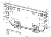
- the multi-axis hinge 140 can be in rotational engagement with the access panel 110 to promote a sequence of motion of the door 130.
- the access panel 110 can comprise one or more hinge engagement members 180 each configured to form a rotational engagement with the panel engagement member 162 of the fixed axis body 142 of the multi-axis hinge 140.
- the hinge engagement member 180 is correspondingly shaped to the panel engagement member 162.
- the hinge engagement member 180 can comprise a substantially cylindrical bore configured to receive the panel engagement member.
- the hinge engagement member 180 can comprise a substantially cylindrical pillar configured to be received by the panel engagement member 162 ( FIG. 6 ).
- the hinge engagement member 180 can comprise a delimiting body 182 that extends away from the access panel 110.
- the delimiting body 182 can extend from a panel recess 184 formed in the access panel 110 adjacent to the doorway 112.
- the delimiting body 182 can cooperate with the first cantilevered detent 172 to bound the motion of the fixed axis body 142, i.e., the delimiting body 184 and the first cantilevered detent 172 can mitigate separation of the hinge engagement member 180 and the panel engagement member 162.
- the multi-axis hinge 140 can be in rotational and sliding engagement with the door 130 to promote a sequence of motion of the door 130.
- the door 130 can comprise one or more sliding engagement members 186 each configured to form a rotational and sliding engagement with the door engagement member 170 of the articulating body 144 of the multi-axis hinge 140. Accordingly, the door 130 can translate with respect to the sliding rotational axis 168.
- the sliding engagement member 186 is correspondingly shaped to the door engagement member 170.
- the sliding engagement members 186 can comprise an elongate slot configured to receive the door engagement member 170 in a rotational and sliding engagement.
- the sliding engagement members 186 can comprise a substantially cylindrical pillar configured to be received by the door engagement member 170 ( FIG. 6 ).
- the sliding engagement members 186 can comprise a guide body 188 that extends away from the door 130.
- the guide body 188 can extend from a door recess 190.
- the guide body 188 can extend along a substantially linear path that is substantially perpendicular to the fixed axis of rotation 132.
- the guide body 188 can cooperate with the second cantilevered detent 174 of the articulating body 144 to promote linear translation of the door 130 with respect to the access panel 110 and bound the motion of the articulating body 144.
- the multi-axis hinge 140 can be in rotational engagement with the access panel 110 and in rotational and sliding engagement with the door 130 to promote a sequence of motion of the door 130 with respect to the access panel 110.
- the door 130 can be provided in a first state 10. When in the first state 10, the door 130 can be in a closed and locked position. Specifically, the door 130 can substantially enclose the doorway 112 of the access panel 110. The door 130 can be secured to the access panel 110 such that rotation of the door 130 around the fixed axis of rotation 132 is mitigated. For example, the peg members 133 of the door 130 can be received within the pocket members 114 of the access panel 100.
- the locking member 136 of the peg member 133 can be received by the cavity bounded by the pocket member 114. It is noted that, when in the first state 10, the fixed axis of rotation 132, the hinge rotational axis 146, and the sliding rotational axis 168 can be constrained into substantially linear alignment. It is furthermore noted that the fixed axis of rotation 132, the hinge rotational axis 146, and the sliding rotational axis 168 can be substantially parallel throughout the sequence of motion.
- the door 130 can be moved from the first state 10 to a second state 12. Likewise, the door 130 can be moved from the second state 12 to the first state 10.
- the door 130 can be in a closed and unlocked position. Specifically, the door 130 can substantially enclose the doorway 112 of the access panel 110.
- the door 130 can be unsecured from the access panel 110 such that rotation of the door 130 around the fixed axis of rotation 132 is permitted.
- the peg members 133 of the door 130 can be offset from the pocket members 114 of the access panel 100 and positioned within the span 124 between the pocket members 114. In some embodiments, the span 124 can be larger than the peg members 133. Accordingly, rotation of the door 130 around the fixed axis of rotation 132 can be unobstructed by the pocket members 114.
- the access panel 110 can comprise a panel engagement feature 191 such as a recess or corrugation provided along the bottom of the doorway 112 that is configured to receive a bottom edge 192 of the door 130.
- a panel engagement feature 191 such as a recess or corrugation provided along the bottom of the doorway 112 that is configured to receive a bottom edge 192 of the door 130.
- the panel engagement feature 191 can overlap the bottom edge 192 of the door 130 such that rotation of the door 130 around the fixed axis of rotation 132 is mitigated.
- the amount of overlap can be less the span 124 between the pocket members 114. Accordingly, motion of the door 130 can be unobstructed by the panel engagement feature 191 when the door 130 is in the second state 12.
- the door 130 can translate between the first state 10 and the second state 12 via substantially vertical motion along the doorway 112. Specifically, the door 130 can translate with respect to the sliding rotational axis 168.
- the sliding engagement member 186 of the door 130 and the door engagement member 170 of the multi-axis hinge 140 can move linearly with respect to one another to transition between the first state 10 and the second state 12.
- the door 130 and the multi-axis hinge 140 can be free to rotate with respect to the fixed axis of rotation 132, the hinge rotational axis 146, and the sliding rotational axis 168.
- the door 130 can be opened by rotating along the fixed axis of rotation 132, the hinge rotational axis 146, the sliding rotational axis 168, or a combination thereof to transition from the second state 12 to a third state 14.
- the door 130 can be closed by rotating along the fixed axis of rotation 132, the hinge rotational axis 146, the sliding rotational axis 168, or a combination thereof to transition from the third state 14 to the second state 12.
- the door 130 can be moved to a fourth state 16 such that the door 130 lays substantially flat with respect to the access panel 110.
- an exterior surface 138 of the door 130 can be placed into contact with an exterior surface 111 of the access panel 110.
- the multi-axis hinge 140 can promote a sequence of motion that permits the door 130 to be rotated throughout a wide angular range when moved throughout the first state 10 and the fourth state 16.
- the wide angular range can be between about 170° and about 190° such as, for example, about 180° in one embodiment.
- multi-axis hinge can be utilized to provide a container with a door that is configured to close and fully open such that the door lays flat against a panel of the container.
- the multi-axis hinges described herein can be provided to allow for a sequence of motion that can permit the use of locking mechanisms such as, for example, a peg and pocket system.
- the container can be provided with a door that is securely closed and easily opened.
- the door can be folded flat to provide substantially unobstructed access to the container via a doorway.
- an explicitly described range of "between about 75° and about 105°” should be considered to include narrower range between (and inclusive of) the minimum value of 75° and the maximum value of 105°; i.e., all ranges beginning with a minimum value of 75° or more and ending with a maximum value of 105°; or less, e.g., between about 75° and about 100°, between about 80° and about 95°, etc.
- directional references such as, but not limited to, vertical, downwards, or the like have been provided for clarity and without limitation. Specifically, it is noted such directional references are made with respect to the normal operation of the containers described herein, i.e., with the container supported by a work surface. Thus, the directions may be reversed or otherwise oriented in any direction by making corresponding changes to the provided directional references with respect to the structure to extend the examples described herein.
Landscapes
- Engineering & Computer Science (AREA)
- Mechanical Engineering (AREA)
- Civil Engineering (AREA)
- Structural Engineering (AREA)
- Closures For Containers (AREA)
- Hinges (AREA)
- Pivots And Pivotal Connections (AREA)
- Rigid Containers With Two Or More Constituent Elements (AREA)
Applications Claiming Priority (2)
| Application Number | Priority Date | Filing Date | Title |
|---|---|---|---|
| US201562217079P | 2015-09-11 | 2015-09-11 | |
| US15/255,375 US10167660B2 (en) | 2015-09-11 | 2016-09-02 | Multi-axis hinges and containers including the same |
Publications (2)
| Publication Number | Publication Date |
|---|---|
| EP3141492A1 true EP3141492A1 (fr) | 2017-03-15 |
| EP3141492B1 EP3141492B1 (fr) | 2020-01-29 |
Family
ID=57121008
Family Applications (1)
| Application Number | Title | Priority Date | Filing Date |
|---|---|---|---|
| EP16187744.4A Active EP3141492B1 (fr) | 2015-09-11 | 2016-09-08 | Conteneur comprenant une porte rabatable ayant un mécanisme d'attache à axes multiples |
Country Status (4)
| Country | Link |
|---|---|
| US (1) | US10167660B2 (fr) |
| EP (1) | EP3141492B1 (fr) |
| CA (2) | CA2941296C (fr) |
| MX (1) | MX2016011763A (fr) |
Cited By (3)
| Publication number | Priority date | Publication date | Assignee | Title |
|---|---|---|---|---|
| WO2018228742A1 (fr) * | 2017-06-14 | 2018-12-20 | Schoeller Allibert Gmbh | Caisse-palette grand volume munie d'un clapet pivotant |
| EP4134321A1 (fr) * | 2021-08-09 | 2023-02-15 | Schoeller Allibert GmbH | Récipient doté d'un dispositif d'articulation verrouillable |
| DE102022000488A1 (de) | 2022-02-08 | 2023-08-10 | Schoeller Allibert Gmbh | Großladungsträger |
Families Citing this family (4)
| Publication number | Priority date | Publication date | Assignee | Title |
|---|---|---|---|---|
| JP6917059B2 (ja) * | 2017-06-08 | 2021-08-11 | 三甲株式会社 | 容器 |
| US20220034142A1 (en) * | 2020-07-31 | 2022-02-03 | Kevin Martin | System, apparatus, and method for storing material |
| US11674346B2 (en) * | 2021-05-12 | 2023-06-13 | Schweitzer Engineering Laboratories, Inc. | Ambidextrous hold open hinge |
| US11834258B2 (en) | 2021-09-03 | 2023-12-05 | A. R. Arena Products, Inc. | Intermediate bulk container systems and methods of using same |
Citations (6)
| Publication number | Priority date | Publication date | Assignee | Title |
|---|---|---|---|---|
| GB2015968A (en) * | 1978-03-09 | 1979-09-19 | Allibert Exploitation | Handling and/or storage case |
| GB2357078A (en) * | 1999-12-09 | 2001-06-13 | Lin Pac Mouldings | Collapsible container assembly |
| GB2426237A (en) * | 2005-05-17 | 2006-11-22 | Rehrig Pacific Co | Collapsible container with a pallet base and walls hinged such that they fold outwards and inwards on different axis |
| US7331480B1 (en) * | 2002-09-27 | 2008-02-19 | Roger Nolan | Articulated hinge apparatus and related methods |
| WO2009023830A1 (fr) * | 2007-08-15 | 2009-02-19 | Orbis Corporation | Système de charnière pour conteneur de vrac modulaire |
| CN102582912A (zh) * | 2012-02-13 | 2012-07-18 | 上海鸿润科技有限公司 | 侧门关闭免提拉的容器 |
Family Cites Families (7)
| Publication number | Priority date | Publication date | Assignee | Title |
|---|---|---|---|---|
| US3330612A (en) * | 1965-07-16 | 1967-07-11 | Honeywell Inc | Cover suspension device |
| US4014458A (en) * | 1976-03-19 | 1977-03-29 | Sanchez Enterprises, Inc. | Three-function container |
| AU6096796A (en) * | 1995-06-07 | 1996-12-30 | Ropak Corporation | Collapsible container with hinged sidewalls |
| WO2001076960A1 (fr) * | 2000-04-07 | 2001-10-18 | Arca Xytec Systems, Inc. | Conteneur demontable dote de parois laterales fermees a panneaux multiples |
| FR2902775B1 (fr) * | 2006-06-21 | 2011-08-05 | Peugeot Citroen Automobiles Sa | Conteneur modulable et empilable |
| US20080169285A1 (en) * | 2007-01-16 | 2008-07-17 | Nick Marazita | Collapsible container |
| US8757412B2 (en) * | 2012-01-09 | 2014-06-24 | Monoflo International, Inc. | Foldable container with access opening |
-
2016
- 2016-09-02 US US15/255,375 patent/US10167660B2/en active Active
- 2016-09-07 CA CA2941296A patent/CA2941296C/fr not_active Expired - Fee Related
- 2016-09-07 CA CA3039617A patent/CA3039617A1/fr not_active Abandoned
- 2016-09-08 EP EP16187744.4A patent/EP3141492B1/fr active Active
- 2016-09-09 MX MX2016011763A patent/MX2016011763A/es active IP Right Grant
Patent Citations (6)
| Publication number | Priority date | Publication date | Assignee | Title |
|---|---|---|---|---|
| GB2015968A (en) * | 1978-03-09 | 1979-09-19 | Allibert Exploitation | Handling and/or storage case |
| GB2357078A (en) * | 1999-12-09 | 2001-06-13 | Lin Pac Mouldings | Collapsible container assembly |
| US7331480B1 (en) * | 2002-09-27 | 2008-02-19 | Roger Nolan | Articulated hinge apparatus and related methods |
| GB2426237A (en) * | 2005-05-17 | 2006-11-22 | Rehrig Pacific Co | Collapsible container with a pallet base and walls hinged such that they fold outwards and inwards on different axis |
| WO2009023830A1 (fr) * | 2007-08-15 | 2009-02-19 | Orbis Corporation | Système de charnière pour conteneur de vrac modulaire |
| CN102582912A (zh) * | 2012-02-13 | 2012-07-18 | 上海鸿润科技有限公司 | 侧门关闭免提拉的容器 |
Cited By (10)
| Publication number | Priority date | Publication date | Assignee | Title |
|---|---|---|---|---|
| WO2018228742A1 (fr) * | 2017-06-14 | 2018-12-20 | Schoeller Allibert Gmbh | Caisse-palette grand volume munie d'un clapet pivotant |
| DE102017113053A1 (de) * | 2017-06-14 | 2018-12-20 | Schoeller Allibert Gmbh | Großladungsträger mit Schwenkklappe |
| CN110770135A (zh) * | 2017-06-14 | 2020-02-07 | 舒乐埃丽伯特有限公司 | 具有枢转翻盖的重型载具 |
| CN110770135B (zh) * | 2017-06-14 | 2021-09-21 | 舒乐埃丽伯特有限公司 | 具有枢转翻盖的重型载具 |
| EP3971100A1 (fr) * | 2017-06-14 | 2022-03-23 | Schoeller Allibert GmbH | Support de charges à grande capacité pourvu de rabat pivotant |
| US11453527B2 (en) | 2017-06-14 | 2022-09-27 | Schoeller Allibert Gmbh | Heavy load carrier with swivel flap |
| DE102017113053B4 (de) | 2017-06-14 | 2023-01-05 | Schoeller Allibert Gmbh | Großladungsträger mit Schwenkklappe |
| EP4134321A1 (fr) * | 2021-08-09 | 2023-02-15 | Schoeller Allibert GmbH | Récipient doté d'un dispositif d'articulation verrouillable |
| DE102022000488A1 (de) | 2022-02-08 | 2023-08-10 | Schoeller Allibert Gmbh | Großladungsträger |
| EP4227238A1 (fr) | 2022-02-08 | 2023-08-16 | Schoeller Allibert GmbH | Support de charge de grande dimension |
Also Published As
| Publication number | Publication date |
|---|---|
| US20170074017A1 (en) | 2017-03-16 |
| CA2941296A1 (fr) | 2017-03-11 |
| EP3141492B1 (fr) | 2020-01-29 |
| US10167660B2 (en) | 2019-01-01 |
| CA3039617A1 (fr) | 2017-03-11 |
| CA2941296C (fr) | 2019-05-28 |
| MX2016011763A (es) | 2018-03-08 |
Similar Documents
| Publication | Publication Date | Title |
|---|---|---|
| EP3141492A1 (fr) | Conteneur comprenant une porte rabatable ayant un mécanisme d'attache à axes multiples | |
| FI123448B (fi) | Häkki tavaroiden käsittelyä tai säilyttämistä varten | |
| EP1043239B1 (fr) | Récipient à parois repliables | |
| US10507973B2 (en) | Foldable container | |
| US9050986B2 (en) | Roll container | |
| US4923079A (en) | Collapsible container | |
| CN110772008B (zh) | 便携式容器和相关联的联接组件 | |
| AU2001273891A1 (en) | A container with collapsible sides | |
| US9398806B2 (en) | Snap together safety storage cabinet | |
| US20140252018A1 (en) | Hinge System For a Modular Bulk Container | |
| EP2726379B1 (fr) | Receptacle en plastique a paroi laterale repliable, et utilisation d'un receptacle | |
| JP2018518426A (ja) | 容器 | |
| KR20190112769A (ko) | 잠금구 및 이를 구비하는 팔레트 박스 | |
| US9452881B2 (en) | Cargo locker with doors | |
| JP6977980B2 (ja) | 輸送用コンテナ | |
| FI127110B (en) | Door, closing system and logistics container | |
| DK2899132T3 (en) | Container with lockable cargo opening | |
| JP2014118179A (ja) | 折畳み容器 | |
| EP2397416A1 (fr) | Conteneur de transport et de stockage pliable | |
| EP3170762A1 (fr) | Conteneur de transport | |
| EP3286097B1 (fr) | Boîte pliante avec mécanisme de verrouillage protégé | |
| NL9500208A (nl) | Een verbeterde opvouwbare container voor het verpakken, transporteren en tonen van verschillende artikelen. | |
| EP4227238A1 (fr) | Support de charge de grande dimension | |
| EP4134321A1 (fr) | Récipient doté d'un dispositif d'articulation verrouillable | |
| EP1790575A1 (fr) | Conteneur pliable |
Legal Events
| Date | Code | Title | Description |
|---|---|---|---|
| PUAI | Public reference made under article 153(3) epc to a published international application that has entered the european phase |
Free format text: ORIGINAL CODE: 0009012 |
|
| STAA | Information on the status of an ep patent application or granted ep patent |
Free format text: STATUS: THE APPLICATION HAS BEEN PUBLISHED |
|
| AK | Designated contracting states |
Kind code of ref document: A1 Designated state(s): AL AT BE BG CH CY CZ DE DK EE ES FI FR GB GR HR HU IE IS IT LI LT LU LV MC MK MT NL NO PL PT RO RS SE SI SK SM TR |
|
| AX | Request for extension of the european patent |
Extension state: BA ME |
|
| STAA | Information on the status of an ep patent application or granted ep patent |
Free format text: STATUS: REQUEST FOR EXAMINATION WAS MADE |
|
| 17P | Request for examination filed |
Effective date: 20170914 |
|
| RBV | Designated contracting states (corrected) |
Designated state(s): AL AT BE BG CH CY CZ DE DK EE ES FI FR GB GR HR HU IE IS IT LI LT LU LV MC MK MT NL NO PL PT RO RS SE SI SK SM TR |
|
| STAA | Information on the status of an ep patent application or granted ep patent |
Free format text: STATUS: EXAMINATION IS IN PROGRESS |
|
| 17Q | First examination report despatched |
Effective date: 20171205 |
|
| GRAP | Despatch of communication of intention to grant a patent |
Free format text: ORIGINAL CODE: EPIDOSNIGR1 |
|
| STAA | Information on the status of an ep patent application or granted ep patent |
Free format text: STATUS: GRANT OF PATENT IS INTENDED |
|
| INTG | Intention to grant announced |
Effective date: 20190517 |
|
| GRAS | Grant fee paid |
Free format text: ORIGINAL CODE: EPIDOSNIGR3 |
|
| GRAJ | Information related to disapproval of communication of intention to grant by the applicant or resumption of examination proceedings by the epo deleted |
Free format text: ORIGINAL CODE: EPIDOSDIGR1 |
|
| GRAL | Information related to payment of fee for publishing/printing deleted |
Free format text: ORIGINAL CODE: EPIDOSDIGR3 |
|
| STAA | Information on the status of an ep patent application or granted ep patent |
Free format text: STATUS: EXAMINATION IS IN PROGRESS |
|
| INTC | Intention to grant announced (deleted) | ||
| GRAP | Despatch of communication of intention to grant a patent |
Free format text: ORIGINAL CODE: EPIDOSNIGR1 |
|
| STAA | Information on the status of an ep patent application or granted ep patent |
Free format text: STATUS: GRANT OF PATENT IS INTENDED |
|
| GRAA | (expected) grant |
Free format text: ORIGINAL CODE: 0009210 |
|
| STAA | Information on the status of an ep patent application or granted ep patent |
Free format text: STATUS: THE PATENT HAS BEEN GRANTED |
|
| INTG | Intention to grant announced |
Effective date: 20191202 |
|
| AK | Designated contracting states |
Kind code of ref document: B1 Designated state(s): AL AT BE BG CH CY CZ DE DK EE ES FI FR GB GR HR HU IE IS IT LI LT LU LV MC MK MT NL NO PL PT RO RS SE SI SK SM TR |
|
| REG | Reference to a national code |
Ref country code: GB Ref legal event code: FG4D |
|
| REG | Reference to a national code |
Ref country code: CH Ref legal event code: EP |
|
| REG | Reference to a national code |
Ref country code: AT Ref legal event code: REF Ref document number: 1228365 Country of ref document: AT Kind code of ref document: T Effective date: 20200215 |
|
| REG | Reference to a national code |
Ref country code: IE Ref legal event code: FG4D |
|
| REG | Reference to a national code |
Ref country code: DE Ref legal event code: R096 Ref document number: 602016028594 Country of ref document: DE |
|
| REG | Reference to a national code |
Ref country code: NL Ref legal event code: MP Effective date: 20200129 |
|
| PG25 | Lapsed in a contracting state [announced via postgrant information from national office to epo] |
Ref country code: PT Free format text: LAPSE BECAUSE OF FAILURE TO SUBMIT A TRANSLATION OF THE DESCRIPTION OR TO PAY THE FEE WITHIN THE PRESCRIBED TIME-LIMIT Effective date: 20200621 Ref country code: NO Free format text: LAPSE BECAUSE OF FAILURE TO SUBMIT A TRANSLATION OF THE DESCRIPTION OR TO PAY THE FEE WITHIN THE PRESCRIBED TIME-LIMIT Effective date: 20200429 Ref country code: FI Free format text: LAPSE BECAUSE OF FAILURE TO SUBMIT A TRANSLATION OF THE DESCRIPTION OR TO PAY THE FEE WITHIN THE PRESCRIBED TIME-LIMIT Effective date: 20200129 Ref country code: RS Free format text: LAPSE BECAUSE OF FAILURE TO SUBMIT A TRANSLATION OF THE DESCRIPTION OR TO PAY THE FEE WITHIN THE PRESCRIBED TIME-LIMIT Effective date: 20200129 |
|
| REG | Reference to a national code |
Ref country code: LT Ref legal event code: MG4D |
|
| PG25 | Lapsed in a contracting state [announced via postgrant information from national office to epo] |
Ref country code: BG Free format text: LAPSE BECAUSE OF FAILURE TO SUBMIT A TRANSLATION OF THE DESCRIPTION OR TO PAY THE FEE WITHIN THE PRESCRIBED TIME-LIMIT Effective date: 20200429 Ref country code: IS Free format text: LAPSE BECAUSE OF FAILURE TO SUBMIT A TRANSLATION OF THE DESCRIPTION OR TO PAY THE FEE WITHIN THE PRESCRIBED TIME-LIMIT Effective date: 20200529 Ref country code: HR Free format text: LAPSE BECAUSE OF FAILURE TO SUBMIT A TRANSLATION OF THE DESCRIPTION OR TO PAY THE FEE WITHIN THE PRESCRIBED TIME-LIMIT Effective date: 20200129 Ref country code: SE Free format text: LAPSE BECAUSE OF FAILURE TO SUBMIT A TRANSLATION OF THE DESCRIPTION OR TO PAY THE FEE WITHIN THE PRESCRIBED TIME-LIMIT Effective date: 20200129 Ref country code: LV Free format text: LAPSE BECAUSE OF FAILURE TO SUBMIT A TRANSLATION OF THE DESCRIPTION OR TO PAY THE FEE WITHIN THE PRESCRIBED TIME-LIMIT Effective date: 20200129 Ref country code: GR Free format text: LAPSE BECAUSE OF FAILURE TO SUBMIT A TRANSLATION OF THE DESCRIPTION OR TO PAY THE FEE WITHIN THE PRESCRIBED TIME-LIMIT Effective date: 20200430 |
|
| PG25 | Lapsed in a contracting state [announced via postgrant information from national office to epo] |
Ref country code: NL Free format text: LAPSE BECAUSE OF FAILURE TO SUBMIT A TRANSLATION OF THE DESCRIPTION OR TO PAY THE FEE WITHIN THE PRESCRIBED TIME-LIMIT Effective date: 20200129 |
|
| PG25 | Lapsed in a contracting state [announced via postgrant information from national office to epo] |
Ref country code: ES Free format text: LAPSE BECAUSE OF FAILURE TO SUBMIT A TRANSLATION OF THE DESCRIPTION OR TO PAY THE FEE WITHIN THE PRESCRIBED TIME-LIMIT Effective date: 20200129 Ref country code: DK Free format text: LAPSE BECAUSE OF FAILURE TO SUBMIT A TRANSLATION OF THE DESCRIPTION OR TO PAY THE FEE WITHIN THE PRESCRIBED TIME-LIMIT Effective date: 20200129 Ref country code: LT Free format text: LAPSE BECAUSE OF FAILURE TO SUBMIT A TRANSLATION OF THE DESCRIPTION OR TO PAY THE FEE WITHIN THE PRESCRIBED TIME-LIMIT Effective date: 20200129 Ref country code: CZ Free format text: LAPSE BECAUSE OF FAILURE TO SUBMIT A TRANSLATION OF THE DESCRIPTION OR TO PAY THE FEE WITHIN THE PRESCRIBED TIME-LIMIT Effective date: 20200129 Ref country code: EE Free format text: LAPSE BECAUSE OF FAILURE TO SUBMIT A TRANSLATION OF THE DESCRIPTION OR TO PAY THE FEE WITHIN THE PRESCRIBED TIME-LIMIT Effective date: 20200129 Ref country code: RO Free format text: LAPSE BECAUSE OF FAILURE TO SUBMIT A TRANSLATION OF THE DESCRIPTION OR TO PAY THE FEE WITHIN THE PRESCRIBED TIME-LIMIT Effective date: 20200129 Ref country code: SM Free format text: LAPSE BECAUSE OF FAILURE TO SUBMIT A TRANSLATION OF THE DESCRIPTION OR TO PAY THE FEE WITHIN THE PRESCRIBED TIME-LIMIT Effective date: 20200129 Ref country code: SK Free format text: LAPSE BECAUSE OF FAILURE TO SUBMIT A TRANSLATION OF THE DESCRIPTION OR TO PAY THE FEE WITHIN THE PRESCRIBED TIME-LIMIT Effective date: 20200129 |
|
| REG | Reference to a national code |
Ref country code: DE Ref legal event code: R097 Ref document number: 602016028594 Country of ref document: DE |
|
| REG | Reference to a national code |
Ref country code: AT Ref legal event code: MK05 Ref document number: 1228365 Country of ref document: AT Kind code of ref document: T Effective date: 20200129 |
|
| PLBE | No opposition filed within time limit |
Free format text: ORIGINAL CODE: 0009261 |
|
| STAA | Information on the status of an ep patent application or granted ep patent |
Free format text: STATUS: NO OPPOSITION FILED WITHIN TIME LIMIT |
|
| 26N | No opposition filed |
Effective date: 20201030 |
|
| PG25 | Lapsed in a contracting state [announced via postgrant information from national office to epo] |
Ref country code: IT Free format text: LAPSE BECAUSE OF FAILURE TO SUBMIT A TRANSLATION OF THE DESCRIPTION OR TO PAY THE FEE WITHIN THE PRESCRIBED TIME-LIMIT Effective date: 20200129 Ref country code: AT Free format text: LAPSE BECAUSE OF FAILURE TO SUBMIT A TRANSLATION OF THE DESCRIPTION OR TO PAY THE FEE WITHIN THE PRESCRIBED TIME-LIMIT Effective date: 20200129 |
|
| PG25 | Lapsed in a contracting state [announced via postgrant information from national office to epo] |
Ref country code: PL Free format text: LAPSE BECAUSE OF FAILURE TO SUBMIT A TRANSLATION OF THE DESCRIPTION OR TO PAY THE FEE WITHIN THE PRESCRIBED TIME-LIMIT Effective date: 20200129 Ref country code: SI Free format text: LAPSE BECAUSE OF FAILURE TO SUBMIT A TRANSLATION OF THE DESCRIPTION OR TO PAY THE FEE WITHIN THE PRESCRIBED TIME-LIMIT Effective date: 20200129 |
|
| REG | Reference to a national code |
Ref country code: DE Ref legal event code: R119 Ref document number: 602016028594 Country of ref document: DE |
|
| PG25 | Lapsed in a contracting state [announced via postgrant information from national office to epo] |
Ref country code: MC Free format text: LAPSE BECAUSE OF FAILURE TO SUBMIT A TRANSLATION OF THE DESCRIPTION OR TO PAY THE FEE WITHIN THE PRESCRIBED TIME-LIMIT Effective date: 20200129 |
|
| REG | Reference to a national code |
Ref country code: CH Ref legal event code: PL |
|
| GBPC | Gb: european patent ceased through non-payment of renewal fee |
Effective date: 20200908 |
|
| REG | Reference to a national code |
Ref country code: BE Ref legal event code: MM Effective date: 20200930 |
|
| PG25 | Lapsed in a contracting state [announced via postgrant information from national office to epo] |
Ref country code: LU Free format text: LAPSE BECAUSE OF NON-PAYMENT OF DUE FEES Effective date: 20200908 |
|
| PG25 | Lapsed in a contracting state [announced via postgrant information from national office to epo] |
Ref country code: FR Free format text: LAPSE BECAUSE OF NON-PAYMENT OF DUE FEES Effective date: 20200930 Ref country code: DE Free format text: LAPSE BECAUSE OF NON-PAYMENT OF DUE FEES Effective date: 20210401 |
|
| PG25 | Lapsed in a contracting state [announced via postgrant information from national office to epo] |
Ref country code: CH Free format text: LAPSE BECAUSE OF NON-PAYMENT OF DUE FEES Effective date: 20200930 Ref country code: BE Free format text: LAPSE BECAUSE OF NON-PAYMENT OF DUE FEES Effective date: 20200930 Ref country code: IE Free format text: LAPSE BECAUSE OF NON-PAYMENT OF DUE FEES Effective date: 20200908 Ref country code: GB Free format text: LAPSE BECAUSE OF NON-PAYMENT OF DUE FEES Effective date: 20200908 Ref country code: LI Free format text: LAPSE BECAUSE OF NON-PAYMENT OF DUE FEES Effective date: 20200930 |
|
| PG25 | Lapsed in a contracting state [announced via postgrant information from national office to epo] |
Ref country code: TR Free format text: LAPSE BECAUSE OF FAILURE TO SUBMIT A TRANSLATION OF THE DESCRIPTION OR TO PAY THE FEE WITHIN THE PRESCRIBED TIME-LIMIT Effective date: 20200129 Ref country code: MT Free format text: LAPSE BECAUSE OF FAILURE TO SUBMIT A TRANSLATION OF THE DESCRIPTION OR TO PAY THE FEE WITHIN THE PRESCRIBED TIME-LIMIT Effective date: 20200129 Ref country code: CY Free format text: LAPSE BECAUSE OF FAILURE TO SUBMIT A TRANSLATION OF THE DESCRIPTION OR TO PAY THE FEE WITHIN THE PRESCRIBED TIME-LIMIT Effective date: 20200129 |
|
| PG25 | Lapsed in a contracting state [announced via postgrant information from national office to epo] |
Ref country code: MK Free format text: LAPSE BECAUSE OF FAILURE TO SUBMIT A TRANSLATION OF THE DESCRIPTION OR TO PAY THE FEE WITHIN THE PRESCRIBED TIME-LIMIT Effective date: 20200129 Ref country code: AL Free format text: LAPSE BECAUSE OF FAILURE TO SUBMIT A TRANSLATION OF THE DESCRIPTION OR TO PAY THE FEE WITHIN THE PRESCRIBED TIME-LIMIT Effective date: 20200129 |