EP3141203A1 - Ablationseinrichtung zur grossflächigen mukosaablation - Google Patents
Ablationseinrichtung zur grossflächigen mukosaablation Download PDFInfo
- Publication number
- EP3141203A1 EP3141203A1 EP15184682.1A EP15184682A EP3141203A1 EP 3141203 A1 EP3141203 A1 EP 3141203A1 EP 15184682 A EP15184682 A EP 15184682A EP 3141203 A1 EP3141203 A1 EP 3141203A1
- Authority
- EP
- European Patent Office
- Prior art keywords
- ablation device
- head
- ablation
- electrodes
- channel
- Prior art date
- Legal status (The legal status is an assumption and is not a legal conclusion. Google has not performed a legal analysis and makes no representation as to the accuracy of the status listed.)
- Granted
Links
Images


Classifications
-
- A—HUMAN NECESSITIES
- A61—MEDICAL OR VETERINARY SCIENCE; HYGIENE
- A61B—DIAGNOSIS; SURGERY; IDENTIFICATION
- A61B18/00—Surgical instruments, devices or methods for transferring non-mechanical forms of energy to or from the body
- A61B18/04—Surgical instruments, devices or methods for transferring non-mechanical forms of energy to or from the body by heating
- A61B18/042—Surgical instruments, devices or methods for transferring non-mechanical forms of energy to or from the body by heating using additional gas becoming plasma
-
- A—HUMAN NECESSITIES
- A61—MEDICAL OR VETERINARY SCIENCE; HYGIENE
- A61B—DIAGNOSIS; SURGERY; IDENTIFICATION
- A61B18/00—Surgical instruments, devices or methods for transferring non-mechanical forms of energy to or from the body
- A61B18/04—Surgical instruments, devices or methods for transferring non-mechanical forms of energy to or from the body by heating
- A61B18/12—Surgical instruments, devices or methods for transferring non-mechanical forms of energy to or from the body by heating by passing a current through the tissue to be heated, e.g. high-frequency current
-
- A—HUMAN NECESSITIES
- A61—MEDICAL OR VETERINARY SCIENCE; HYGIENE
- A61B—DIAGNOSIS; SURGERY; IDENTIFICATION
- A61B18/00—Surgical instruments, devices or methods for transferring non-mechanical forms of energy to or from the body
- A61B18/04—Surgical instruments, devices or methods for transferring non-mechanical forms of energy to or from the body by heating
- A61B18/12—Surgical instruments, devices or methods for transferring non-mechanical forms of energy to or from the body by heating by passing a current through the tissue to be heated, e.g. high-frequency current
- A61B18/14—Probes or electrodes therefor
- A61B18/1492—Probes or electrodes therefor having a flexible, catheter-like structure, e.g. for heart ablation
-
- A—HUMAN NECESSITIES
- A61—MEDICAL OR VETERINARY SCIENCE; HYGIENE
- A61B—DIAGNOSIS; SURGERY; IDENTIFICATION
- A61B17/00—Surgical instruments, devices or methods
- A61B2017/00477—Coupling
-
- A—HUMAN NECESSITIES
- A61—MEDICAL OR VETERINARY SCIENCE; HYGIENE
- A61B—DIAGNOSIS; SURGERY; IDENTIFICATION
- A61B18/00—Surgical instruments, devices or methods for transferring non-mechanical forms of energy to or from the body
- A61B2018/00053—Mechanical features of the instrument of device
- A61B2018/00166—Multiple lumina
-
- A—HUMAN NECESSITIES
- A61—MEDICAL OR VETERINARY SCIENCE; HYGIENE
- A61B—DIAGNOSIS; SURGERY; IDENTIFICATION
- A61B18/00—Surgical instruments, devices or methods for transferring non-mechanical forms of energy to or from the body
- A61B2018/00315—Surgical instruments, devices or methods for transferring non-mechanical forms of energy to or from the body for treatment of particular body parts
- A61B2018/00482—Digestive system
- A61B2018/00494—Stomach, intestines or bowel
-
- A—HUMAN NECESSITIES
- A61—MEDICAL OR VETERINARY SCIENCE; HYGIENE
- A61B—DIAGNOSIS; SURGERY; IDENTIFICATION
- A61B18/00—Surgical instruments, devices or methods for transferring non-mechanical forms of energy to or from the body
- A61B2018/00571—Surgical instruments, devices or methods for transferring non-mechanical forms of energy to or from the body for achieving a particular surgical effect
- A61B2018/00577—Ablation
-
- A—HUMAN NECESSITIES
- A61—MEDICAL OR VETERINARY SCIENCE; HYGIENE
- A61B—DIAGNOSIS; SURGERY; IDENTIFICATION
- A61B18/00—Surgical instruments, devices or methods for transferring non-mechanical forms of energy to or from the body
- A61B2018/00571—Surgical instruments, devices or methods for transferring non-mechanical forms of energy to or from the body for achieving a particular surgical effect
- A61B2018/00595—Cauterization
-
- A—HUMAN NECESSITIES
- A61—MEDICAL OR VETERINARY SCIENCE; HYGIENE
- A61B—DIAGNOSIS; SURGERY; IDENTIFICATION
- A61B18/00—Surgical instruments, devices or methods for transferring non-mechanical forms of energy to or from the body
- A61B2018/0091—Handpieces of the surgical instrument or device
-
- A—HUMAN NECESSITIES
- A61—MEDICAL OR VETERINARY SCIENCE; HYGIENE
- A61B—DIAGNOSIS; SURGERY; IDENTIFICATION
- A61B18/00—Surgical instruments, devices or methods for transferring non-mechanical forms of energy to or from the body
- A61B2018/00982—Surgical instruments, devices or methods for transferring non-mechanical forms of energy to or from the body combined with or comprising means for visual or photographic inspections inside the body, e.g. endoscopes
-
- A—HUMAN NECESSITIES
- A61—MEDICAL OR VETERINARY SCIENCE; HYGIENE
- A61B—DIAGNOSIS; SURGERY; IDENTIFICATION
- A61B18/00—Surgical instruments, devices or methods for transferring non-mechanical forms of energy to or from the body
- A61B18/04—Surgical instruments, devices or methods for transferring non-mechanical forms of energy to or from the body by heating
- A61B18/12—Surgical instruments, devices or methods for transferring non-mechanical forms of energy to or from the body by heating by passing a current through the tissue to be heated, e.g. high-frequency current
- A61B18/14—Probes or electrodes therefor
- A61B2018/1467—Probes or electrodes therefor using more than two electrodes on a single probe
-
- A—HUMAN NECESSITIES
- A61—MEDICAL OR VETERINARY SCIENCE; HYGIENE
- A61B—DIAGNOSIS; SURGERY; IDENTIFICATION
- A61B18/00—Surgical instruments, devices or methods for transferring non-mechanical forms of energy to or from the body
- A61B18/04—Surgical instruments, devices or methods for transferring non-mechanical forms of energy to or from the body by heating
- A61B18/12—Surgical instruments, devices or methods for transferring non-mechanical forms of energy to or from the body by heating by passing a current through the tissue to be heated, e.g. high-frequency current
- A61B18/14—Probes or electrodes therefor
- A61B18/16—Indifferent or passive electrodes for grounding
- A61B2018/167—Passive electrodes capacitively coupled to the skin
Definitions
- the invention relates to an ablation device, in particular for mucosa ablation.
- the therapeutic mucosa ablation e.g. tumor ablation or destruction of gastric wall-influencing cells, advantageously for weight loss, is typically performed by endoscopic intervention, whereby special probes may be used for ablation.
- an endoscope with an end cap is known to be placed on the mucosa and in the interior of an argon plasma coagulation is performed.
- the cap is intended to limit the area of action of argon plasma coagulation and thus define mucosal coagulation.
- Extensive mucosa ablation poses special challenges to the practitioner in terms of patience and dexterity. This in particular when flexible instruments intended for general use, such as polypectomy snares or the like, are used. With such loops only a resection of the mucosa of about 2 cm 2 is performed in one step. In the fundus and cardia area of the stomach, resection using a flexible endoscope is very difficult. There is also the risk of perforation.
- Ablation of the mucosa should be rejected in the same way as too low a level of exposure, as it could damage tissue layers underneath, as well as perforating the stomach.
- the ablation device has a head with two channels and electrodes arranged in the channels.
- the channels and / or the electrodes enclose an acute angle with each other. This is preferably between 10 ° and 60 °, preferably it is 10 ° to 30 °, more preferably 25 °.
- the channels are gas ducts through which suitable gas, such as argon, can be passed. In this way, an argon plasma can be generated with the aid of sparks emanating from the electrodes, which can be used to coagulate the tissue lying in front of the electrodes.
- the ablation device has at least two electrodes, it is preferably a monopolar instrument. This means that the neutral electrode is not provided on the instrument, but is attached over a large area to the patient. The current flow thus takes place between the biological tissue and the electrodes of the ablation device.
- the channels and / or arranging the electrodes at an acute angle to each other, it can be achieved that the plasma currents emanating from the two channels diverge and coagulate a broad strip-like region of the mucosa when the ablation device is moved along the mucosa.
- the plasma streams emerging from the two channels can together form an approximately fan-shaped current, i. a jet of non-circular (e.g., oval or strip-like) cross-section.
- the outlet openings of the two channels are preferably on a line which is oriented transversely to the direction of movement of the ablation device.
- the amount of gas and the electrical impingement of the two electrodes can be achieved that across the width of the coagulated strip of mucosa a more uniform , results in the therapeutic sense uniform depth of action. This makes it possible to achieve uniform and extensive tissue ablation.
- the concept according to the invention paves the way to the design of a particularly narrow, slender head which can hardly be wider or, in individual cases, narrower than the trace of coagulated mucosal tissue produced by it.
- This in turn makes it possible to simplify the handling and installation of the ablation device on an endoscope, in particular the attachment of the ablation device to the distal end of the endoscope, whereby its channels remain free for other instruments and for the extraction of smoke.
- the endoscope and the attached ablation device can be arranged in a film tube. This may have two separate lumens so that the endoscope is passed through a lumen and the ablation device through the second lumen.
- a guide element for example a spiral tube may be used, in which the ablation device is displaceable.
- the displaceability of the head of the ablation device in the axial direction, i. in the longitudinal direction of the endoscope, facilitates handling especially in the ablation of tissue layers in large hollow organs, such as ablation of the mucosa in the stomach.
- the head of the device can be extended, for example, between 0 mm and 100 mm, with an extendability of up to 50 mm as an advantage, further 30 mm extension length considered optimal.
- the head has a non-circular cross section at its distal end and the socket assigned to it has a corresponding complementary recess into which the head can retract in the proximal direction when retracted.
- the head is thereby limited in the socket in its rotational mobility. This greatly facilitates the handling of the ablation device.
- it can be ensured that the head is arranged by retreating in a specific rotational position, which he maintains even after pushing out.
- the head can advantageously be brought in the extended state by a survey on the tube at the proximal end of the socket by a groove provided for this purpose in a desired position.
- a fluid duct can also be arranged on the head, which is used to eject a fluid jet, for example a jet of water can serve.
- a fluid jet for example a jet of water can serve.
- the mouth of this channel is preferably arranged between the mouths of the gas channels.
- a liquid jet may be formed with a pressure or flow required, for example, to inject the mucosa.
- the gas channels are preferably provided with a ceramic lining. This allows for continuous operation of the ablation device, especially for ablation of larger areas of the mucosa.
- the two electrodes are preferably electrically insulated from each other and connected to separate leads.
- the two supply lines can be guided through a common gas supply channel or through separate gas supply channels.
- the two electrodes are alternately supplied with electrical power via the separate lines, whereby a particularly uniform ablation effect and a uniform coagulation depth measured across the width of the generated ablation strip can be achieved. This is especially true if alternating high-frequency voltage in the range of several hundred kHz is applied to the two electrodes, wherein the switching frequency (alternation frequency) between the two electrodes is a few Hz.
- the power delivered to the electrodes may be, for example, between 10 W and 200 W, for example 80 W or 120 W. Further details of advantageous embodiments of the invention are the subject of the description, the drawings or claims. Show it:
- FIG. 1 an ablation device according to the invention on an endoscope in use, in a schematic representation
- FIG. 2 one end of an endoscope with ablation device placed thereon, in a sectional side view
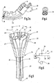
- FIG. 3a / 3b / 3c the endoscope with the ablation device after FIG. 2 , in perspective view
- FIG. 4 the endoscope and the ablation device after FIG. 2 and 3 , in front view
- FIG. 5 the ablation device, in a sectioned sectional view
- FIG. 6 the electrical wiring of the ablation device, as a circuit diagram
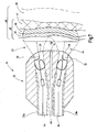
- FIG. 7 a modified embodiment of an ablation device in a schematic, longitudinal sectional view in operation when exposed to the mucosa.
- the ablation device 11 of the invention attached to an endoscope 10 is illustrated during the process of mucosal ablation on a stomach 12.
- the endoscope 10 and the ablation device 11 are inserted through the esophagus 13 into the interior of the stomach 12.
- Operating elements 14 permit the movement of the endoscope 10 such that, for example, a distal end 15 of the endoscope 10 can be curved in a targeted manner and / or moved along the stomach inner wall, as a result of which different locations of the inner stomach wall can be easily reached.
- the endoscope 10 may include one or more channels 16 (see 3a ), in which work equipment, such as surgical instruments, can be introduced and can be added and removed via the gaseous and liquid fluids.
- the endoscope 10 may include image transfer means to visually control the treatment.
- FIGS. 2 to 4 illustrate the distal end 15 of the endoscope 10 with the ablation device 11 attached thereto. It is arranged together with the endoscope 10 in a tubular sheath 17 which contains a first lumen 18 for the ablation device 11 and a second lumen 19 for the endoscope 10.
- the first and / or the second lumens 18, 19 may, as in FIG. 2 and 3 illustrated slit formed to facilitate curving of the endoscope.
- the tubular sheath 17 may consist of a thin plastic film which encloses the endoscope 10 and the ablation device 11 with a corresponding clearance.
- the ablation device 11 is formed in the present embodiment as externally attached to the endoscope 10, along the same extending device.
- the ablation device may also be designed as a device guided within an endoscope.
- it has a head 20, which is preferably movably mounted, preferably in the axial direction 21, which coincides with the longitudinal direction of the distal end of the endoscope 10.
- the head 20 is associated with a socket 22 which is held in or on the endoscope 10.
- the socket 22 has a passage opening into which the head 20 can retract and through which a supply hose 23 for the head 20 extends.
- the supply hose 23 is preferably tension and compression stiff, but easily bendable. Therefore, the head 20 can be reciprocated in the axial direction 21 by pushing or pulling the hose 23 back and forth accordingly.
- the head 20 is in FIG. 4 illustrated in plan view and in FIG. 5 shown separately in longitudinal section. It can be seen that the head 20 has a deviating from the circular cross section, in particular an oval cross section. In any case, the deviation of the cross section of the passage opening of the socket 22 and the shape of the head 20 are such that the head 20 finds when retreating into the through hole of the socket 22 and thereby rotates in the desired angular position.
- the head 20 preferably has a circular cross-section at its proximal end 24. He is trained there as a circular cone, for example. The cross-section of the cone then proceeds gradually from the proximal end 24 in the direction of the distal end 25 in the FIG. 4 apparent oval shape, wherein the outer surface of the head 20 is free of steps, which could be at the mouth of the through hole of the socket 22 and thus hinder the retraction of the head 20.
- This design contributes significantly to the handling ease of the ablation device 11. If the head 20 is pushed far out of the socket 20, so that only the proximal end 24 is in the socket 22 or that the head 20 is pushed out of the socket 20, the head 20 can be rotated by turning the relatively stiff supply hose 23 in FIG various Angular positions are rotated. However, if the head 20 is retracted, it will find its way into the socket 22, which will then rotate the head 20 to the predetermined angular position. The transfer of the head 20 in the in FIG. 3 and 4 illustrated target position is thus automatically given by a positive connection between the head 20 and the socket 22.
- the shape of the head 20 and the socket 22 are coordinated so that not only in its final position, when fully retracted into the socket 22, the head 20 is fixed in the radial direction, but substantially maintains this orientation until the head 20 completely out of the socket 22.
- the length of the axial displacement, wherein the head 20 substantially retains its position in the radial direction is 15 mm, preferably 10 mm, particularly preferably 8 mm.
- the head 20 may be made of a heat-resistant, electrically non-thermally and slightly thermally conductive material, such as heat-resistant plastic, thermoset, ceramic or the like. It is also possible to head 20, as in FIG. 5 indicated to be made of plastic and provided with ceramic inserts 26, 27, for example in tube form. The head can also be formed entirely of ceramic.
- this anti-twist device 53 has a protruding shaped nose in the form of a spring 51.
- This spring 51 dips into a provided on the socket 22 groove 52, and thus secures in the extended state of the head 20, the desired position ( Figure 3c ).
- the anti-rotation 53 may for example be designed as a plastic extrusion.
- the anti-rotation 53 may be formed so that it forms an end stop together with the socket 22, the maximum length limited, the head 20 can be moved in the axial direction. It is possible to arrange the anti-rotation device 53 at a distance from the holder 22 on the supply hose 23, thereby ensuring the rotational orientation of the head 20 in each axial position. For this purpose, it is then necessary that shortly before leaving the head 20 from the socket 22, the spring 51 already engages in the groove 52 or at least partially engages.
- the anti-rotation device 53 it is also possible to arrange the anti-rotation device 53 so that the head 20 is held freely movable between its end regions in the direction of rotation. With such an arrangement, the rotational fixation of the head 20 is granted until it leaves the socket 22, and again when the spring 51 enters the groove 52.
- the fixed direction of rotation of the head 20 in the regions of its respective end positions can each occupy approximately 15 mm. In between, the head 20 can be kept freely movable about 20 mm also in the radial direction.
- the head 20 encloses at least two channels 28, 29, which serve to supply the treatment site gas, in particular inert gas such as argon. However, it is also possible to supply active gases, aerosols or the like, for which purpose the channels 28, 29 can equally serve.
- the channels 28, 29 fed via the single supply hose 23 together with gas.
- the channels 28, 29 may have a circular cross section or deviating cross sections such as oval cross section, polygonal cross sections or the like. At their openings they have differently oriented opening axes 30, 31, which in FIG.
- the opening axes are the central axes of the openings of the channels 28, 29 and enclose an angle ⁇ with one another, which is preferably in the range between 10 and 60 °, preferably between 10 ° and 30 ° and in the preferred case is 25 °.
- the channels 28, 29 can also be combined to form a common channel with oval cross section or slot cross section, in which both electrodes 32, 33 are arranged.
- the distance between the electrodes 32, 33 is preferably several millimeters (3 mm to 12 mm), with a distance of 5 mm to 10 mm, in particular 7.5 mm is advantageous to achieve a uniform broad-stripe tissue ablation with a homogeneous Ablationstiefe.
- the diameter of the electrodes is preferably in the range of 0.2 mm to 1 mm, wherein in the present embodiment, a diameter of 0.4 mm has been selected. On the other hand, this has proven advantageous on account of the high field strengths occurring due to the small wire diameter and therefore the good ignitability of the electrodes on the one hand and the tissue effects to be achieved therewith on the other hand.
- rod-shaped or needle-shaped electrodes 32, 33 are arranged, which are oriented longitudinally to the opening axes 30, 31.
- the tips of the electrodes 32, 33 may be within the channels 28, 29 or, as it is FIG. 5 suggests, look out of these.
- the electrodes 32, 33 which may for example be formed of a refractory metal such as tungsten, are by suitable means, in FIG. 5 symbolically indicated by a resilient conductor loop, approximately centrally held in the channels 28, 29.
- leads 34, 35 are connected, which are electrically insulated from each other and lead through the supply tube 23.
- FIG. 6 illustrates, the lines 34, 35 connected via a switch assembly 36 to an electrical source 37, for example in the form of a high-frequency generator 38.
- This provides an RF voltage of several hundred kHz (for example 350 kHz) and a suitable voltage above 1000 V (eg 4500 V).
- the HF generator 38 can produce a power of more than 100 W (for example, 120 W).
- the voltage is provided relative to a zero potential to which the patient is connected via at least one neutral electrode 39.
- This neutral electrode 39 is attached over a large area at a suitable location of the patient's body.
- the switch assembly 36 connects the leads 34, 35 and thus the electrodes 32, 33 alternately, i. alternately with the output of the electrical source 37.
- the switching frequency at which the electrodes 32, 33 are alternately activated is in the range of a few Hz, preferably between 1 Hz and 20 Hz, preferably 5 Hz.
- a fluid conduit 40 may extend through the supply tube 23 and be connected to a nozzle provided on the end face of the head 20.
- the nozzle has at its distal end an outlet opening 41 through which a liquid, for example sodium chloride solution, for example, can be ejected as a jet. This allows tissue sections to be processed, for example, injected, when the jet emerges with the appropriate pressure, flow and shape, so that it can penetrate into the tissue like a needle.
- the ablation device 11 described so far operates as follows: For planar ablation of the mucosa, for example for the therapeutic treatment of diseased tissue changes, for influencing the weight and eating behavior of patients or for other therapeutic reasons, the endoscope 10 provided with the ablation device 11 is moved as shown in FIG FIG. 1 introduced through the esophagus 13 of the patient in the stomach 12. By means of the control elements 14 of the endoscope 10 whose distal end 15 is positioned at the desired ablation site so that the tissue site to be treated in the field of view of the Endoscope 10 is located. The head 20 of the ablation device 1 is then slightly advanced by corresponding displacement of the supply tube 13, so that it is at the desired distance, for example 3 mm, to the mucosa 42.
- fluid Prior to thermal ablation of mucosa 42 by way of example, fluid is introduced into the gastric wall 49 through the outlet 41 in such a way that a fluid cushion advantageously forms below the desired ablation site.
- gas such as argon.
- the generator 38 and the switch assembly 36 are activated so that the electrodes 32, 33 can be alternately ignited and skip a spark to the mucosa 42.
- the enveloping argon beam forms in front of each electrode 30, 31 a plasma jet 43, 44, the example of the embodiment according to FIG. 7 is apparent. They can combine to form a fan-shaped jet.
- the plasma jets 43, 44 meet at a time offset from each other on the mucosa 42 and coagulate their top layer, in particular their epithelium 45 and the lamina Propria 46 and parts of the submucosa 47.
- the Muscularis Propria 48 is preferably spared by previously formed the liquid pad.
- the alternating activation of the two plasma jets at 5 Hz leads macroscopically to the unification of the plasma jets 43, 44.
- a broad fabric strip 50 with a uniform depth of action is coagulated.
- the width of the fabric strip 50 may be about 10 mm and in some cases about 14 mm by the angular arrangement of the electrodes 32, 33 and the channels 28, 29.
- the treatment continues as the user guides the head 20 along a pathway across the mucosa by means of the controls 14 of the endoscope 10 and by appropriately guiding the supply tube 23 (see FIG FIG. 7 perpendicular to the plane of the drawing), leaving a coagulated strip of tissue about 12 mm to 14 mm wide. In this way, the mucosa 42 to be coagulated in high reliability with reduced risk of muscularis damage.
- FIG. 7 illustrates a modified embodiment of the ablation device 11.
- the difference is in the formation of the head 20, the channels 28, 29 are fed by separate supply tubes 23a, 23b. Accordingly, the lines 34, 35 without separate insulation in these supply hoses 23a, 23b are performed.
- the above description applies accordingly for this embodiment, based on the same reference numerals.
- the ablation device 11 is characterized by a head 20 having a non-circular cross-section and electrodes 32, 33 which are at an acute angle to one another. Due to the angular arrangement of the electrodes and corresponding formation of the channels 28, 29, an approximately fan-shaped plasma jet is obtained with which, in particular with alternating activation of the two electrodes, a broad stripe-shaped ablation region, for example, hollow organs of living beings can be achieved.
- the handling is reliable and simplified and the treatment time compared to existing measures shortened.
Landscapes
- Health & Medical Sciences (AREA)
- Life Sciences & Earth Sciences (AREA)
- Surgery (AREA)
- Engineering & Computer Science (AREA)
- Plasma & Fusion (AREA)
- General Health & Medical Sciences (AREA)
- Otolaryngology (AREA)
- Physics & Mathematics (AREA)
- Veterinary Medicine (AREA)
- Biomedical Technology (AREA)
- Heart & Thoracic Surgery (AREA)
- Medical Informatics (AREA)
- Molecular Biology (AREA)
- Animal Behavior & Ethology (AREA)
- Nuclear Medicine, Radiotherapy & Molecular Imaging (AREA)
- Public Health (AREA)
- Cardiology (AREA)
- Surgical Instruments (AREA)
Abstract
Description
- Die Erfindung betrifft eine Ablationsvorrichtung insbesondere für die Mucosaablation.
- Die therapeutische Mucosaablation, z.B. zur Tumorablation oder Zerstörung von das Essverhalten beeinflussenden Zellen der Magenwand, vorteilhafthafterweise zur Gewichtsreduktion, wird typischerweise durch endoskopische Intervention durchgeführt, wobei zur Ablation spezielle Sonden zur Anwendung kommen können.
- Beispielsweise ist dazu aus der
WO 2011/022069 A ein Endoskop mit einer Endkappe bekannt, die auf die Mucosa aufzusetzen ist und in deren Innenraum eine Argonplasmakoagulation durchgeführt wird. Die Kappe soll den Einwirkungsbereich der Argonplasmakoagulation begrenzen und somit die Mucosakoagulation definieren. - Aus der
US 8 641 711 B2 ist ein Instrument zur Abtragung von Gewebeschichten von Hohlorganen bekannt, wobei das Instrument einen elektrisch aktiven Kopf mit Elektroden aufweist, an dem ein expandierbares Element vorgesehen ist, um den Kopf des Instruments in Bezug auf die gegenüber liegende Gewebewand definiert zu positionieren. Dieses Instrument setzt Hohlorgane mit beschränktem Durchmesser voraus, wie es zum Beispiel im Darm der Fall ist. - Die großflächige Mucosaablation stellt an den Behandler besondere Herausforderungen hinsichtlich Geduld und Fingerfertigkeit. Dies insbesondere, wenn dazu für den allgemeinen Gebrauch vorgesehene flexible Instrumente, wie Polypektomieschlingen oder dergleichen, eingesetzt werden. Mit solchen Schlingen wird in einem Arbeitsschritt lediglich eine Resektion der Mucosa von ca. 2 cm2 ausgeführt. Im Fundus- und Cardia-Bereich des Magens ist eine Resektion mit Hilfe eines flexiblen Endoskops sehr schwierig. Außerdem besteht das Risiko der Perforation.
- Bei der Ablation der Mucosa ist eine nicht ausreichende Ablation ebenso abzulehnen wie eine zu tiefe Einwirkung, weil dadurch darunter liegende Gewebeschichten geschädigt werden könnten, bis hin zur Perforation des Magens.
- Es besteht demnach der Wunsch nach einem Instrument und einem Verfahren, nach dem sich die Mucosaablation prozesssicher und gegebenenfalls über größere Flächen erstreckend und in guter Qualität durchführen lässt.
- Diese Aufgabe wird mit dem Instrument nach Anspruch 1 und einem Verfahren nach Anspruch 16 gelöst.
- Die erfindungsgemäße Ablationsvorrichtung weist einen Kopf mit zwei Kanälen und in den Kanälen angeordneten Elektroden auf. Die Kanäle und/oder die Elektroden schließen miteinander einen spitzen Winkel ein. Dieser liegt vorzugsweise zwischen 10° und 60°, vorzugsweise beträgt er 10° bis 30°, weiter vorzugsweise 25°. Die Kanäle sind Gasleitungskanäle, durch die geeignetes Gas, wie beispielsweise Argon, geleitet werden kann. Damit kann mit Hilfe von den Elektroden ausgehender Funken ein Argon-Plasma erzeugt werden, das zu einer Koagulation des vor den Elektroden liegenden Gewebes genutzt werden kann. Obwohl die Ablationsvorrichtung wenigstens zwei Elektroden aufweist, ist sie vorzugsweise ein monopolares Instrument. Dies bedeutet, dass die Neutralelektrode nicht an dem Instrument vorgesehen ist, sondern großflächig an dem Patienten befestigt wird. Der Stromfluss findet somit zwischen dem biologischen Gewebe und den Elektroden der Ablationsvorrichtung statt.
- Durch die Anordnung der Kanäle und/oder durch die Anordnung der Elektroden in einem spitzen Winkel zueinander kann erreicht werden, dass die von den beiden Kanälen ausgehenden Plasmaströme divergieren und einen breiten streifenförmigen Bereich der Mucosa koagulieren, wenn die Ablationsvorrichtung entlang der Mucosa bewegt wird. Die aus den beiden Kanälen austretenden Plasmaströme können gemeinsam einen etwa fächerförmigen Strom bilden, d.h. einen Strahl mit nichtkreisförmigem (z.B. ovalem oder streifenartigem) Querschnitt. Die Austrittsöffnungen der beiden Kanäle liegen vorzugsweise auf einer Linie, die quer zur Bewegungsrichtung der Ablationsvorrichtung orientiert ist. Bei geeigneter Festlegung des Winkels zwischen den beiden Kanälen und/oder zwischen den beiden Elektroden sowie der Ausströmgeschwindigkeit des Gases aus den Kanälen, der Gasmenge sowie der elektrischen Beaufschlagung der beiden Elektroden kann erreicht werden, dass sich über die Breite des koagulierten Streifens der Mucosa eine einheitlichere, im therapeutischen Sinne einheitliche Wirkungstiefe ergibt. Damit lässt sich eine gleichmäßig und großflächige Gewebeablation erreichen.
- Das erfindungsgemäße Konzept ebnet den Weg zu der Gestaltung eines besonders schmalen, schlanken Kopfs der kaum breiter oder im Einzelfall auch schmaler sein kann als die von ihm erzeugte Spur koagulierten Mucosagewebes. Dies ermöglicht wiederum eine Vereinfachung der Handhabung und den Anbau der Ablationsvorrichtung an einem Endoskop, insbesondere das Befestigen der Ablationsvorrichtung an dem distalen Ende des Endoskops, wodurch dessen Kanäle für weitere Instrumente sowie zur Absaugung von Rauch frei bleiben. Das Endoskop sowie die aufgesetzte Ablationsvorrichtung können in einem Folienschlauch angeordnet sein. Dieser kann zwei getrennte Lumen aufweisen, so dass das Endoskop durch ein Lumen und die Ablationsvorrichtung durch das zweite Lumen geführt wird. In das Lumen für die Ablationsvorrichtung kann ein Führungselement, beispielsweise ein Spiralschlauch eingesetzt sein, in welchem die Ablationsvorrichtung verschiebbar ist.
- Die Verschiebbarkeit des Kopfs der Ablationsvorrichtung in Axialrichtung, d.h. in Längsrichtung des Endoskops, erleichtert die Handhabung insbesondere bei der Ablation von Gewebeschichten in großen Hohlorganen, wie beispielsweise Ablation der Mucosa im Magen. Der Kopf der Vorrichtung kann zum Beispiel zwischen 0 mm und 100 mm ausgefahren werden, wobei eine Ausfahrbarkeit bis 50 mm als vorteilhaft, weiter werden 30mm Ausfahrlänge als optimal angesehen.
- Es wird als besonders vorteilhaft angesehen, wenn der Kopf an seinem distalen Ende einen unrunden Querschnitt aufweist und die ihm zugeordnete Fassung eine entsprechende komplementäre Ausnehmung aufweist, in die der Kopf bei Rückzug in proximaler Richtung einfahren kann. Der Kopf wird dadurch in der Fassung in seiner Drehbeweglichkeit eingeschränkt. Dies erleichtert die Handhabung der Ablationsvorrichtung erheblich. Insbesondere kann sichergestellt werden, dass der Kopf durch Rückzug in einer bestimmten Drehlage angeordnet ist, die er auch nach dem Ausschieben beibehält. Der Kopf kann vorteilhaft auch in dem ausgefahrenen Zustand durch eine Erhebung am Schlauch am proximalen Ende der Fassung durch eine dafür vorgesehene Nut in einer gewünschten Lage gebracht werden.
- An dem Kopf kann neben einem oder mehreren Gasleitungskanälen auch ein Fluidleitungskanal angeordnet sein, der zum Ausstoßen eines Fluidstrahls beispielsweise eines Wasserstrahls dienen kann. Die Mündung dieses Kanals ist vorzugsweise zwischen den Mündungen der Gaskanäle angeordnet. Es kann ein Flüssigkeitsstrahl mit einem zum Beispiel zum Unterspritzen der Mucosa erforderlichen Druck bzw. Flow ausgebildet werden.
- Die Gaskanäle sind vorzugsweise mit einer keramischen Auskleidung versehen. Dies ermöglicht Dauerbetrieb der Ablationsvorrichtung, insbesondere zum Abtragen größerer Bereiche der Mucosa.
- Die beiden Elektroden sind vorzugsweise elektrisch gegeneinander isoliert und an gesonderte Zuleitungen angeschlossen. Die beiden Zuleitungen können durch einen gemeinsamen Gaszuführungskanal oder durch getrennte Gaszuführungskanäle geführt sein. Vorzugsweise werden die beiden Elektroden über die gesonderten Leitungen abwechselnd mit elektrischer Leistung beaufschlagt, wodurch sich ein besonderer gleichmäßiger Ablationseffekt und eine, über die Breite des erzeugten Ablationsstreifens gemessen, einheitliche Koagulationstiefe erreichen lässt. Dies insbesondere, wenn an den beiden Elektroden alternierend hochfrequente Spannung im Bereich mehrerer Hundert kHz anliegt, wobei die Umschaltfrequenz (Alternierungsfrequenz) zwischen beiden Elektroden wenige Hz beträgt. Die an die Elektroden abgegebene Leistung kann beispielsweise zwischen 10 W und 200 W, beispielsweise 80 W oder 120 W betragen. Weitere Einzelheiten vorteilhafter Ausführungsformen der Erfindung sind Gegenstand der Beschreibung, der Zeichnung oder von Ansprüchen. Es zeigen:
-
Figur 1 eine erfindungsgemäße Ablationsvorrichtung an einem Endoskop im Einsatz, in schematischer Darstellung, -
Figur 2 ein Ende eines Endoskops mit darauf aufgesetzter Ablationsvorrichtung, in ausschnittsweiser Seitenansicht, -
Figur 3a /3b/ 3c das Endoskop mit der Ablationsvorrichtung nachFigur 2 , in perspektivischer Ansicht, -
Figur 4 das Endoskop und die Ablationsvorrichtung nachFigur 2 und3 , in Stirnansicht, -
Figur 5 die Ablationsvorrichtung, in ausschnittsweiser Schnittdarstellung, -
Figur 6 die elektrische Beschaltung der Ablationsvorrichtung, als Schaltschema, und -
Figur 7 eine abgewandelte Ausführungsform einer Ablationsvorrichtung in schematischer, längsgeschnittener Darstellung in Betrieb bei Einwirkung auf die Mucosa. - In
Figur 1 ist die erfindungsgemäße, an einem Endoskop 10 angebrachte Ablationsvorrichtung 11 während des Vorgangs der Mucosaablation an einem Magen 12 veranschaulicht. Zur Behandlung werden das Endoskop 10 und die Ablationsvorrichtung 11 durch die Speiseröhre 13 in den Innenraum des Magens 12 eingefügt. Bedienelemente 14 gestatten dabei die Bewegung des Endoskops 10 so, dass sich beispielsweise ein distales Ende 15 des Endoskops 10 gezielt krümmen und/oder entlang der Mageninnenwand bewegen lässt, wodurch verschiedene Stellen der Mageninnenwand leicht erreichbar sind. Das Endoskop 10 kann ein oder mehrere Kanäle 16 (sieheFig.3a ) enthalten, in die Arbeitsmittel, wie beispielsweise chirurgische Instrumente, eingeführt werden können und über die gasförmige und flüssige Fluide zu oder abgeführt werden können. Außerdem kann das Endoskop 10 Mittel zur Bildübertragung enthalten, um die Behandlung optisch kontrollieren zu können. - Die
Figuren 2 bis 4 veranschaulichen das distale Ende 15 des Endoskops 10 mit der daran befestigten Ablationsvorrichtung 11. Diese ist gemeinsam mit dem Endoskop 10 in einer Schlauchhülle 17 angeordnet, die ein erstes Lumen 18 für die Ablationsvorrichtung 11 und ein zweites Lumen 19 für das Endoskop 10 enthält. Das erste und/oder das zweite Lumen 18, 19 können, wie inFigur 2 und3 veranschaulicht, geschlitzt ausgebildet sein, um ein Krümmen des Endoskops zu erleichtern. Die Schlauchhülle 17 kann aus einer dünnen Kunststofffolie bestehen, die das Endoskop 10 und die Ablationsvorrichtung 11 mit entsprechendem Spiel umschließt. - Die Ablationsvorrichtung 11 ist im vorliegenden Ausführungsbeispiel als an dem Endoskop 10 außen angebrachte, sich längs desselben erstreckende Vorrichtung ausgebildet. Die Erfindung ist darauf jedoch nicht beschränkt. Die Ablationsvorrichtung kann auch als innerhalb eines Endoskops geführte Vorrichtung ausgebildet sein. Jedenfalls weist sie einen Kopf 20 auf, der vorzugsweise beweglich gelagert, vorzugsweise in Axialrichtung 21 beweglich ist, die mit der Längsrichtung des distalen Endes des Endoskops 10 übereinstimmt. Dem Kopf 20 ist eine Fassung 22 zugeordnet, die in oder an dem Endoskop 10 gehalten ist. Die Fassung 22 weist eine Durchgangsöffnung auf, in die der Kopf 20 einfahren kann und durch die sich ein Versorgungsschlauch 23 für den Kopf 20 erstreckt. Der Versorgungsschlauch 23 ist vorzugsweise zug- und drucksteif, jedoch leicht biegbar. Deswegen kann der Kopf 20 in Axialrichtung 21 hin und her bewegt werden, indem der Schlauch 23 entsprechend hin und her geschoben bzw. gezogen wird.
- Der Kopf 20 ist in
Figur 4 in Draufsicht veranschaulicht und inFigur 5 gesondert im Längsschnitt dargestellt. Es ist ersichtlich, dass der Kopf 20 einen von der Kreisform abweichenden Querschnitt aufweist, insbesondere einen Ovalquerschnitt. Jedenfalls sind die Abweichung des Querschnitts der Durchgangsöffnung der Fassung 22 und die Form des Kopfes 20 derart, dass der Kopf 20 beim Rückziehen in die Durchgangsöffnung der Fassung 22 findet und sich dabei in die gewünschte Winkelposition dreht. Um dies zu bewirken, weist der Kopf 20 vorzugsweise an seinem proximalen Ende 24 einen Kreisquerschnitt auf. Er ist dort zum Beispiel als Kreiskegel ausgebildet. Der Querschnitt des Kegels geht dann ausgehend vom proximalen Ende 24 in Richtung des distalen Endes 25 allmählich in die ausFigur 4 ersichtliche Ovalform über, wobei die Außenfläche des Kopf 20 frei von Stufen ist, die an der Mündung der Durchgangsöffnung der Fassung 22 aufsetzen und somit das Rückziehen des Kopfs 20 behindern könnten. - Diese Bauform trägt erheblich zur Handhabungserleichterung der Ablationsvorrichtung 11 bei. Wird der Kopf 20 weit aus der Fassung 20 herausgeschoben, so dass lediglich noch das proximale Ende 24 in der Fassung 22 steht oder dass der Kopf 20 ganz aus der Fassung 20 rausgeschoben ist, kann der Kopf 20 über ein Drehen des relativ steifen Versorgungsschlauchs 23 in verschiedene Winkelpositionen gedreht werden. Wird der Kopf 20 jedoch zurückgezogen, findet er in die Fassung 22 ein, die den Kopf 20 dann in die vorgegebene Winkelposition dreht. Die Überführung des Kopfs 20 in die in
Figur 3 und4 veranschaulichte Sollposition ist somit automatisch durch Formschluss zwischen dem Kopf 20 und der Fassung 22 gegeben. Die Form des Kopfs 20 und der Fassung 22 sind so aufeinander abgestimmt, dass der Kopf 20 nicht nur in seiner Endposition, wenn er ganz in die Fassung 22 eingezogen ist, in radialer Richtung fixiert ist, sondern diese Orientierung im Wesentlichen beibehält, bis der Kopf 20 komplett aus der Fassung 22 austritt. Dadurch ist es möglich, den Kopf 20 in axialer Richtung zu verschieben, und trotzdem behält er seine Rotationsorientierung im Wesentlichen bei. Die Länge der axialen Verschiebung, wobei der Kopf 20 seine Position in radialer Richtung im Wesentlichen beibehält, beträgt 15 mm, vorzugsweise 10 mm, besonders vorzugsweise 8 mm. Der Kopf 20 kann aus einem hitzebeständigen, elektrisch nicht und thermisch wenig leitenden Material bereitgestellt sein, wie beispielsweise hitzebeständigem Kunststoff, Duroplast, Keramik oder dergleichen. Es ist auch möglich, den Kopf 20, wie inFigur 5 angedeutet, aus Kunststoff auszubilden und mit keramischen Einlagen 26, 27 beispielsweise in Rohrform zu versehen. Der Kopf kann auch im Ganzen aus Keramik ausgebildet sein. - Um die Orientierung des Kopfs 20 in radialer Richtung sicherzustellen, wenn der Kopf 20 in axialer Richtung soweit bewegt worden, dass er aus der Fassung 22 austritt, kann der Versorgungschlauch 23 mit einer Verdrehsicherung 53 gemäß
Figur 3b und 3c ausgebildet sein. Diese Verdrehsicherung 53 weist dazu eine vorstehende Formnase in Form einer Feder 51 auf. Diese Feder 51 taucht in eine an der Fassung 22 vorgesehene Nut 52 ein, und sichert somit im ausgefahrenen Zustand des Kopfs 20 die gewünschte Lage (Figur 3c ). Die Verdrehsicherung 53 kann beispielsweise als Kunststoffumspritzung ausgeführt sein. Die Verdrehsicherung 53 kann so ausgebildet sein, dass sie zusammen mit der Fassung 22 einen Endanschlag bildet, der die maximale Länge begrenzt, die der Kopf 20 in axialer Richtung bewegt werden kann. Es ist möglich, die Verdrehsicherung 53 in einem Abstand zur Fassung 22 am Versorgungsschlauch 23 anzuordnen, so dass dadurch die Rotationsorientierung des Kopfs 20 in jeder Axialposition sichergestellt ist. Dazu ist es dann erforderlich, dass kurz vor dem Verlassen des Kopfs 20 aus der Fassung 22 die Feder 51 bereits in die Nut 52 eingreift oder wenigstens teilweise eingreift. - Es ist auch möglich, die Verdrehsicherung 53 so anzuordnen, dass der Kopf 20 zwischen seinen Endbereichen in Rotationsrichtung frei beweglich gehalten ist. Bei solch einer Anordnung ist die Rotationsfixierung des Kopfs 20 solange gewährt, bis er die Fassung 22 verlässt, und dann wieder, wenn die Feder 51 in die Nut 52 eintritt. Bei einer gesamten Axialbewegung des Kopfs 20 von beispielsweise 50 mm kann die fixierte Rotationsrichtung des Kopfs 20 in den Bereichen seiner jeweiligen Endlagen jeweils ca. 15 mm einnehmen. Dazwischen kann der Kopf 20 ca. 20 mm auch in radialer Richtung frei beweglich gehalten sein.
- Der Kopf 20 umschließt wenigstens zwei Kanäle 28, 29, die dazu dienen, dem Behandlungsort Gas, insbesondere Inertgas wie beispielsweise Argon, zuzuführen. Es können jedoch auch Aktivgase, Aerosole oder dergleichen zuzuführen sein, wozu die Kanäle 28, 29 gleichermaßen dienen können. Im vorliegenden Ausführungsbeispiel werden die Kanäle 28, 29 über den einzigen Versorgungsschlauch 23 gemeinsam mit Gas gespeist. Die Kanäle 28, 29 können einen Kreisquerschnitt oder auch abweichende Querschnitte wie Ovalquerschnitt, Mehreckquerschnitte oder dergleichen aufweisen. An ihren Öffnungen weisen sie unterschiedlich orientierte Öffnungsachsen 30, 31 auf, die in
Figur 5 durch strichpunktierte Linien markiert sind, die Öffnungsachsen sind die Mittelachsen der Öffnungen der Kanäle 28, 29 und schließen miteinander einen Winkel α ein, der vorzugsweise im Bereich zwischen 10 und 60°, vorzugsweise zwischen 10° und 30° liegt und im bevorzugten Fall 25° beträgt. Die Kanäle 28, 29 können auch zu einem gemeinsamen Kanal mit Ovalquerschnitt oder Schlitzquerschnitt vereinigt sein, in dem beide Elektroden 32, 33 angeordnet sind. - Der Abstand zwischen den Elektroden 32, 33 beträgt vorzugsweise mehrere Millimeter (3 mm bis 12 mm), wobei ein Abstand von 5 mm bis 10 mm, insbesondere 7,5 mm vorteilhaft ist, um eine gleichmäßige breitstreifige Gewebeablation mit homogener Ablationstiefe zu erreichen. Der Durchmesser der Elektroden liegt vorzugsweise im Bereich von 0,2 mm bis 1 mm, wobei im vorliegenden Ausführungsbeispiel ein Durchmesser von 0,4 mm gewählt worden ist. Dies hat sich wegen der aufgrund des geringen Drahtdurchmessers auftretenden hohen Feldstärken und deswegen der guten Zündwilligkeit der Elektroden einerseits und der damit zu erzielenden Gewebeeffekte anderseits als vorteilhaft herausgestellt.
- Vorzugsweise mittig in den Öffnungen der Kanäle 28, 29 sind stab- oder nadelförmige Elektroden 32, 33 angeordnet, die längs zu den Öffnungsachsen 30, 31 orientiert sind. Die Spitzen der Elektroden 32, 33 können innerhalb der Kanäle 28, 29 liegen oder, wie es
Figur 5 andeutet, aus diesen herausschauen. Die Elektroden 32, 33, die beispielsweise aus einem hitzebeständigen Metall wie Wolfram ausgebildet sein können, sind durch geeignete Mittel, inFigur 5 symbolisch angedeutet durch eine federnde Leiterschleife, etwa zentrisch in den Kanälen 28, 29 gehalten. An die Elektroden 32, 33 sind Zuleitungen 34, 35 angeschlossen, die gegeneinander elektrisch isoliert sind und durch den Versorgungsschlauch 23 führen. WieFigur 6 veranschaulicht, sind die Leitungen 34, 35 über eine Schalteranordnung 36 mit einer elektrischen Quelle 37 zum Beispiel in Gestalt eines Hochfrequenzgenerators 38 angeschlossen. Dieser stellt eine HF-Spannung mit mehreren hundert kHz (zum Beispiel 350 kHz) und einer geeigneten Spannung oberhalb 1000 V (z.B. 4500 V) bereit. Der HF-Generator 38 kann eine Leistung vom mehr als 100 W (zum Beispiel 120 W) aufbringen. - Die Spannung wird bezogen auf ein Null-Potential bereitgestellt, an das der Patient über mindestens eine Neutralelektrode 39 angeschlossen ist. Diese Neutralelektrode 39 wird großflächig an einer geeigneten Stelle des Körpers des Patienten angebracht. Die Schalteranordnung 36 verbindet die Leitungen 34, 35 und somit die Elektroden 32, 33 alternierend, d.h. abwechselnd mit dem Ausgang der elektrischen Quelle 37. Die Schaltfrequenz, mit der die Elektroden 32, 33 abwechselnd aktiviert werden, liegt im Bereich einiger Hz, vorzugsweise zwischen 1 Hz und 20 Hz, vorzugsweise 5 Hz.
- Zusätzlich kann sich eine Fluidleitung 40 durch den Versorgungsschlauch 23 erstrecken und mit einer an der Stirnseite des Kopfs 20 vorgesehenen Düse verbunden sein. Die Düse weist an ihrem distalen Ende eine Austrittsöffnung 41 auf durch die eine Flüssigkeit, zum Beispiel Natriumchlorid-Lösung, beispielweise als Strahl ausgestoßen werden kann. Damit lassen sich Gewebepartien bearbeiten, beispielsweise unterspritzen, wenn der Strahl mit entsprechendem Druck, Flow und Form austritt, dass er wie eine Nadel in das Gewebe eindringen kann.
- Die insoweit beschriebene Ablationsvorrichtung 11 arbeitet wie folgt: Zur flächenhaften Ablation der Mucosa, beispielsweise zur therapeutischen Behandlung krankhafter Gewebeveränderungen, zur Beeinflussung des Gewichts- und Essverhaltens von Patienten oder aus anderen therapeutischen Gründen, wird das mit der Ablationsvorrichtung 11 versehene Endoskop 10 gemäß
Figur 1 durch die Speiseröhre 13 des Patienten in dessen Magen 12 eingeführt. Mittels der Bedienelemente 14 des Endoskops 10 wird dessen distales Ende 15 an die gewünschte Ablationsstelle so positioniert, dass die zu behandelnde Gewebestelle im Sichtfeld des Endoskops 10 liegt. Es wird nun durch entsprechendes Schieben des Versorgungsschlauchs 13 der Kopf 20 der Ablationsvorrichtung 1 etwas vorgeschoben, so dass er im gewünschten Abstand, beispielsweise 3 mm zu der Mucosa 42 steht. - Vor thermischer Ablation beispielhaft der Mukosa 42 wird durch die Austrittsöffnung 41 Flüssigkeit in die Magenwand 49 so eingebracht, dass sich ein Flüssigkeitskissen vorteilhaft unter der gewünschten Ablationsstelle bildet. Durch die Kanäle 28, 29 strömt Gas, beispielsweise Argon. Es werden nun der Generator 38 und die Schalteranordnung 36 aktiviert, so dass die Elektroden 32, 33 abwechselnd zünden und einen Funken zur Mucosa 42 überspringen lassen. Der einhüllende Argonstrahl bildet vor jeder Elektrode 30, 31 einen Plasmastrahl 43, 44, der am Beispiel der Ausführungsform nach
Figur 7 ersichtlich ist. Sie können sich dabei zu einem fächerförmigen Strahl vereinigen. Die Plasmastrahlen 43, 44 treffen zeitlich versetzt nebeneinander auf der Mucosa 42 auf und koagulieren deren oberste Schicht, insbesondere deren Epithel 45 sowie der Lamina Propria 46 und Teile der Submucosa 47. Die Muscularis Propria 48 wird jedoch durch zuvor gebildete das Flüssigkeitskissen vorzugsweise verschont. - Durch das abwechselnde Ansteuern der beiden Plasmastrahlen mit 5 Hz kommt es makroskopisch zur Vereinigung der Plasmastrahlen 43, 44. So wird ein breiter Gewebestreifen 50 mit einheitlicher Wirktiefe koaguliert. Die Breite des Gewebestreifens 50 kann durch die Winkelanordnung der Elektroden 32, 33 und der Kanäle 28, 29 über 10 mm und im Einzelfall etwa 14 mm betragen. Die Behandlung nimmt ihren Fortgang, indem der Anwender mittels der Bedienelemente 14 des Endoskops 10 und durch entsprechende Führung des Versorgungsschlauchs 23 den Kopf 20 entlang eines Wegs über die Mucosa führt (in
Figur 7 senkrecht zur Zeichenebene), wobei er einen koagulierten Streifen Gewebes von etwa 12 mm bis 14 mm Breite hinterlässt. Auf diese Weise kann die Mucosa 42 in großer Zuverlässigkeit mit reduzierter Gefahr der Muscularisschädigung koaguliert werden. -
Figur 7 veranschaulicht eine abgewandelte Ausführungsform der Ablationsvorrichtung 11. Der Unterschied besteht in der Ausbildung des Kopfs 20, dessen Kanäle 28, 29 von gesonderten Versorgungsschläuchen 23a, 23b gespeist werden. Entsprechend können die Leitungen 34, 35 ohne gesonderte Isolierung in diesen Versorgungschläuchen 23a, 23b geführt werden. Im Übrigen gilt für diese Ausführungsform die obige Beschreibung entsprechend unter Zugrundelegung gleicher Bezugszeichen. - Die erfindungsgemäße Ablationsvorrichtung 11 zeichnet sich durch einen Kopf 20 mit unrundem Querschnitt und in einem spitzen Winkel zueinander stehenden Elektroden 32, 33 aus. Durch die Winkelanordnung der Elektroden und entsprechende Ausbildung der Kanäle 28, 29 ergibt sich ein etwa fächerförmiger Plasmastrahl mit dem insbesondere mit alternierender Aktivierung der beiden Elektroden ein breiter streifenförmiger Ablationsbereich z.B. Hohlorganen von Lebewesen erzielbar ist. Die Handhabung ist zuverlässig und vereinfacht und die Behandlungszeit im Vergleich zu vorhanden Maßnahmen verkürzt.
Bezugszeichen: 10 Endoskop 11 Ablationsvorrichtung 12 Magen 13 Speiseröhre 14 Bedienelemente 15 distales Ende des Endoskops 10 16 Kanal des Endoskops 10 17 Schlauchhülle 18 erstes Lumen der Schlauchhülle 17 19 zweites Lumen der Schlauchhülle 17 20 Kopf 21 Axialrichtung 22 Fassung 23, 23a, 23b Versorgungsschlauch 24 proximales Ende des Kopfs 20 25 distales Ende des Kopfs 20 26, 27 keramische Einlagen 28, 29 Kanäle 30, 31 Öffnungsachsen α Winkel zwischen den Öffnungsachsen 30, 31 32, 33 Elektroden 34, 35 Leitungen 36 Schalteranordnung 37 elektrische Quelle 38 HF-Generator 39 Neutralelektrode 40 Fluidleitung 41 Austrittsöffnung 42 Mucosa 43, 44 Plasmastrahl 45 Epithel 46 Lamina Propria 47 Submucosa 48 Muscularis Propria 49 Magenwand 50 Gewebestreifen 51 Formnase, Feder 52 Nut, Schlitz 53 Verdrehsicherung
Claims (18)
- Ablationsvorrichtung (11), insbesondere für die Mucosaablation,
mit einem Kopf (20), der einen ersten Kanal (28) mit einer wenigstens teilweise darin angeordneten ersten Elektrode (32) und einen zweiten Kanal (29) mit einer wenigstens teilweise darin angeordneten zweite Elektrode (33) aufweist,
wobei der erste Kanal (28) und der zweite Kanal (29) miteinander und/oder die erste Elektrode (32) und die zweite Elektrode (33) miteinander einen spitzen Winkel (α) einschließen. - Ablationsvorrichtung nach Anspruch 1, dadurch gekennzeichnet, dass der erste Kanal (28) und der zweite Kanal (29) Gasleitungskanäle sind.
- Ablationsvorrichtung nach einem der vorstehenden Ansprüche, dadurch gekennzeichnet, dass die Kanäle (28, 29) jeweils eine gerundete Mündung mit zentrisch in dieser platzierten Elektrode (32, 33) aufweisen.
- Ablationsvorrichtung nach einem der vorstehenden Ansprüche, dadurch gekennzeichnet, dass die Kanäle (28, 29) zumindest an ihren distalen Enden aus einem hitzebeständigen Kunststoff oder Keramik ausgebildet sind.
- Ablationsvorrichtung nach einem der vorstehenden Ansprüche, dadurch gekennzeichnet, dass der erste Kanal (28) und der zweite Kanal (29) an eine gemeinsame Versorgungsleitung (23) angeschlossen sind.
- Ablationsvorrichtung nach einem der vorstehenden Ansprüche, dadurch gekennzeichnet, dass der erste Kanal (28) und der zweite Kanal (29) an gesonderte Versorgungsleitungen (23a, 23b) angeschlossen sind.
- Ablationsvorrichtung nach einem der vorstehenden Ansprüche, dadurch gekennzeichnet, dass sich durch die Versorgungsleitung (23, 23a, 23b) eine elektrische Zuleitung (34, 35) für wenigstens eine der Elektroden (32, 33) erstreckt.
- Ablationsvorrichtung nach Anspruch 7, dadurch gekennzeichnet, dass die elektrischen Zuleitungen (34, 35) der beiden Elektroden (32, 33) gegeneinander elektrisch isoliert sind.
- Ablationsvorrichtung nach einem der vorstehenden Ansprüche, dadurch gekennzeichnet, dass der Kopf (20) sich ausgehend von seinem distalen Ende (25) in proximaler Richtung verjüngend ausgebildet ist.
- Ablationsvorrichtung nach einem der vorstehenden Ansprüche, dadurch gekennzeichnet, dass der Kopf (20) an seinem distalen Ende (25) einen unrunden Querschnitt aufweist.
- Ablationsvorrichtung nach einem der vorstehenden Ansprüche, dadurch gekennzeichnet, dass dem Kopf (20) eine Fassung (22) mit einer Halteeinrichtung zu Befestigung an einem Endoskop (10) zugeordnet ist, wobei der Kopf (20) in Bezug auf die Fassung (22) axial beweglich ist.
- Ablationsvorrichtung nach Anspruch 9 und 10, dadurch gekennzeichnet, dass die Drehbeweglichkeit des Kopfs (20) in der Fassung (22) eingeschränkt ist.
- Ablationsvorrichtung nach einem der vorstehenden Ansprüche, dadurch gekennzeichnet, dass an dem Kopf (20) eine Austrittsöffnung (41) für eine Flüssigkeit angeordnet ist.
- Ablationsvorrichtung nach Anspruch 12, dadurch gekennzeichnet, dass die Austrittsöffnung (41) eine Düse ist.
- Ablationsvorrichtung nach Anspruch 12 oder 13, dadurch gekennzeichnet, dass die Austrittsöffnung (41) mittig zwischen den Elektroden (32, 33) angeordnet ist.
- Verfahren zur Gewebeablation, insbesondere Gewebeablation mit einer Ablationsvorrichtung nach Anspruch 1, dadurch gekennzeichnet, dass der Kopf (20) des Instruments quer zu einer die Elektroden (31, 32) verbindenden Linie in einem Abstand zu dem abzutragenden Gewebe entlang eines Weges bewegt wird.
- Verfahren nach Anspruch 16, dadurch gekennzeichnet, dass die an den beiden Elektroden (33, 32) anliegende HF-Spannung alternierend gepulst ist.
- Verfahren nach Anspruch 17 oder 18, dadurch gekennzeichnet, dass vor der thermischen Ablation der Mukosa (42) mittels des Instruments nach einem der Ansprüche 1 bis 15 Flüssigkeit in die Magenwand (49) so eingebracht wird, dass sich unter der gewünschten Ablationsstelle ein Flüssigkeitskissen bildet.
Priority Applications (8)
| Application Number | Priority Date | Filing Date | Title |
|---|---|---|---|
| EP15184682.1A EP3141203B1 (de) | 2015-09-10 | 2015-09-10 | Ablationseinrichtung zur grossflächigen mukosaablation |
| PL15184682T PL3141203T3 (pl) | 2015-09-10 | 2015-09-10 | Urządzenie do ablacji, do przeprowadzania obejmującej dużą powierzchnię ablacji śluzówki |
| BR102016016736-1A BR102016016736B1 (pt) | 2015-09-10 | 2016-07-20 | Dispositivo de ablação para ablação da mucosa de grande área |
| KR1020160111369A KR102280370B1 (ko) | 2015-09-10 | 2016-08-31 | 대면적 점막 절제를 위한 절제 디바이스 |
| JP2016172236A JP6723880B2 (ja) | 2015-09-10 | 2016-09-02 | 広範囲粘膜切除のための切除装置 |
| CN201610805223.4A CN106510838B (zh) | 2015-09-10 | 2016-09-05 | 用于大面积粘膜消融的消融装置 |
| US15/261,392 US10624689B2 (en) | 2015-09-10 | 2016-09-09 | Ablation device for large-area mucosal ablation |
| RU2016136233A RU2724014C1 (ru) | 2015-09-10 | 2016-09-09 | Устройство для абляции слизистой оболочки большой площади |
Applications Claiming Priority (1)
| Application Number | Priority Date | Filing Date | Title |
|---|---|---|---|
| EP15184682.1A EP3141203B1 (de) | 2015-09-10 | 2015-09-10 | Ablationseinrichtung zur grossflächigen mukosaablation |
Publications (2)
| Publication Number | Publication Date |
|---|---|
| EP3141203A1 true EP3141203A1 (de) | 2017-03-15 |
| EP3141203B1 EP3141203B1 (de) | 2022-04-20 |
Family
ID=54106226
Family Applications (1)
| Application Number | Title | Priority Date | Filing Date |
|---|---|---|---|
| EP15184682.1A Active EP3141203B1 (de) | 2015-09-10 | 2015-09-10 | Ablationseinrichtung zur grossflächigen mukosaablation |
Country Status (8)
| Country | Link |
|---|---|
| US (1) | US10624689B2 (de) |
| EP (1) | EP3141203B1 (de) |
| JP (1) | JP6723880B2 (de) |
| KR (1) | KR102280370B1 (de) |
| CN (1) | CN106510838B (de) |
| BR (1) | BR102016016736B1 (de) |
| PL (1) | PL3141203T3 (de) |
| RU (1) | RU2724014C1 (de) |
Cited By (4)
| Publication number | Priority date | Publication date | Assignee | Title |
|---|---|---|---|---|
| EP3412234A1 (de) * | 2017-06-07 | 2018-12-12 | Erbe Elektromedizin GmbH | Instrument mit einem mehrstrominstrumentenkopf zur argon-plasma-koagulation |
| EP3494861A1 (de) | 2017-12-05 | 2019-06-12 | Erbe Elektromedizin GmbH | Vorrichtung mit einem arbeitskanalführungselement |
| EP3661443A4 (de) * | 2017-08-04 | 2021-06-09 | U.S. Patent Innovations LLC | Diffusiver applikator für kaltes atmosphärenplasmasystem |
| CN114271934A (zh) * | 2021-12-09 | 2022-04-05 | 东莞康华医院有限公司 | 一种医用一次性针电极 |
Families Citing this family (8)
| Publication number | Priority date | Publication date | Assignee | Title |
|---|---|---|---|---|
| US20170100190A1 (en) * | 2015-10-12 | 2017-04-13 | Mysore Wifiltronics PVT LTD | High performance material for electro-surgical vaporization electrodes |
| CN109394333A (zh) * | 2018-10-19 | 2019-03-01 | 江苏邦士医疗科技有限公司 | 一种提高内窥镜复合手术功能的等离子体手术器械 |
| US11944281B2 (en) | 2019-02-19 | 2024-04-02 | Olympus Corporation | Method for treating gastro esophageal reflux disease |
| WO2021140609A1 (ja) * | 2020-01-09 | 2021-07-15 | オリンパス株式会社 | 内視鏡用処置具および内視鏡的治療方法 |
| WO2021022510A1 (en) * | 2019-08-07 | 2021-02-11 | Covidien Lp | Electrosurgical systems |
| CN112353484B (zh) * | 2020-10-20 | 2022-02-25 | 上海交通大学 | 一种柔性微传感器系统、可延展柔性器件及制备方法 |
| CN112353489A (zh) * | 2020-11-27 | 2021-02-12 | 安徽康昕医疗器械有限公司 | 一种腹腔手术用滴水型吸引电钩 |
| EP4606333A1 (de) | 2024-02-23 | 2025-08-27 | Erbe Elektromedizin GmbH | Elektrochirurgisches instrument mit kohlenstofffaserelektrode |
Citations (6)
| Publication number | Priority date | Publication date | Assignee | Title |
|---|---|---|---|---|
| WO2000009053A1 (en) * | 1998-08-11 | 2000-02-24 | Arthrocare Corporation | Systems and methods for electrosurgical tissue treatment in the presence of electrically conductive fluid |
| DE10000091A1 (de) * | 2000-01-04 | 2001-07-05 | Ingo F Herrmann | Endoskop |
| WO2008090004A1 (de) * | 2007-01-25 | 2008-07-31 | Erbe Elektromedizin Gmbh | Bipolares instrument und verfahren zur elektrochirurgischen behandlung von gewebe |
| WO2011022069A2 (en) | 2009-08-20 | 2011-02-24 | H. Lee Moffitt Cancer Center & Research Institute | Endoscopic caps for ionized plasma confinement, shaping and control for therapeutic purposes |
| US20110184408A1 (en) * | 2010-01-28 | 2011-07-28 | Bovie Medical Corporation | Electrosurgical apparatus to generate a dual plasma stream and method thereof |
| US8641711B2 (en) | 2007-05-04 | 2014-02-04 | Covidien Lp | Method and apparatus for gastrointestinal tract ablation for treatment of obesity |
Family Cites Families (14)
| Publication number | Priority date | Publication date | Assignee | Title |
|---|---|---|---|---|
| US5730127A (en) * | 1993-12-03 | 1998-03-24 | Avitall; Boaz | Mapping and ablation catheter system |
| GB9900964D0 (en) | 1999-01-15 | 1999-03-10 | Gyrus Medical Ltd | An electrosurgical system |
| US6047700A (en) | 1998-03-30 | 2000-04-11 | Arthrocare Corporation | Systems and methods for electrosurgical removal of calcified deposits |
| US6579270B2 (en) | 1998-06-04 | 2003-06-17 | Alcon Manufacturing, Ltd. | Liquefracture handpiece tip |
| US20050059963A1 (en) | 2003-09-12 | 2005-03-17 | Scimed Life Systems, Inc. | Systems and method for creating transmural lesions |
| DE10351370B4 (de) | 2003-11-04 | 2011-08-11 | Erbe Elektromedizin GmbH, 72072 | Instrument für die Plasma-Koagulation |
| US7658738B2 (en) * | 2004-05-14 | 2010-02-09 | Ethicon Endo-Surgery, Inc. | Medical devices for use with endoscope |
| DE102005038694A1 (de) * | 2005-04-11 | 2006-10-26 | Erbe Elektromedizin Gmbh | Endoskopisches Chirurgiegerät |
| US7625368B2 (en) * | 2005-10-17 | 2009-12-01 | Galil Medical Ltd. | Endometrial ablation device and method |
| DE102009041167B4 (de) * | 2009-09-11 | 2021-08-12 | Erbe Elektromedizin Gmbh | Multifunktionsinstrument und Verfahren zur Verhinderung der Karbonisierung von Gewebe mittels eines Multifunktionsinstrument |
| US20110098704A1 (en) | 2009-10-28 | 2011-04-28 | Ethicon Endo-Surgery, Inc. | Electrical ablation devices |
| US20120029498A1 (en) | 2010-07-30 | 2012-02-02 | Daniel Igor Branovan | Bipolar Radio Frequency Ablation Instrument |
| JP5755121B2 (ja) * | 2011-11-30 | 2015-07-29 | Hoya株式会社 | 内視鏡用高周波処置具 |
| CN202397597U (zh) * | 2011-12-23 | 2012-08-29 | 王广众 | 一种可弯曲双极电极 |
-
2015
- 2015-09-10 EP EP15184682.1A patent/EP3141203B1/de active Active
- 2015-09-10 PL PL15184682T patent/PL3141203T3/pl unknown
-
2016
- 2016-07-20 BR BR102016016736-1A patent/BR102016016736B1/pt active IP Right Grant
- 2016-08-31 KR KR1020160111369A patent/KR102280370B1/ko active Active
- 2016-09-02 JP JP2016172236A patent/JP6723880B2/ja active Active
- 2016-09-05 CN CN201610805223.4A patent/CN106510838B/zh active Active
- 2016-09-09 RU RU2016136233A patent/RU2724014C1/ru active
- 2016-09-09 US US15/261,392 patent/US10624689B2/en active Active
Patent Citations (6)
| Publication number | Priority date | Publication date | Assignee | Title |
|---|---|---|---|---|
| WO2000009053A1 (en) * | 1998-08-11 | 2000-02-24 | Arthrocare Corporation | Systems and methods for electrosurgical tissue treatment in the presence of electrically conductive fluid |
| DE10000091A1 (de) * | 2000-01-04 | 2001-07-05 | Ingo F Herrmann | Endoskop |
| WO2008090004A1 (de) * | 2007-01-25 | 2008-07-31 | Erbe Elektromedizin Gmbh | Bipolares instrument und verfahren zur elektrochirurgischen behandlung von gewebe |
| US8641711B2 (en) | 2007-05-04 | 2014-02-04 | Covidien Lp | Method and apparatus for gastrointestinal tract ablation for treatment of obesity |
| WO2011022069A2 (en) | 2009-08-20 | 2011-02-24 | H. Lee Moffitt Cancer Center & Research Institute | Endoscopic caps for ionized plasma confinement, shaping and control for therapeutic purposes |
| US20110184408A1 (en) * | 2010-01-28 | 2011-07-28 | Bovie Medical Corporation | Electrosurgical apparatus to generate a dual plasma stream and method thereof |
Cited By (7)
| Publication number | Priority date | Publication date | Assignee | Title |
|---|---|---|---|---|
| EP3412234A1 (de) * | 2017-06-07 | 2018-12-12 | Erbe Elektromedizin GmbH | Instrument mit einem mehrstrominstrumentenkopf zur argon-plasma-koagulation |
| US12156687B2 (en) | 2017-06-07 | 2024-12-03 | Erbe Elektromedizin Gmbh | Instrument with a multistream instrument head for argon plasma coagulation |
| EP3661443A4 (de) * | 2017-08-04 | 2021-06-09 | U.S. Patent Innovations LLC | Diffusiver applikator für kaltes atmosphärenplasmasystem |
| EP3494861A1 (de) | 2017-12-05 | 2019-06-12 | Erbe Elektromedizin GmbH | Vorrichtung mit einem arbeitskanalführungselement |
| US11771305B2 (en) | 2017-12-05 | 2023-10-03 | Erbe Elektromedizin Gmbh | Device with a working channel guiding element |
| CN114271934A (zh) * | 2021-12-09 | 2022-04-05 | 东莞康华医院有限公司 | 一种医用一次性针电极 |
| CN114271934B (zh) * | 2021-12-09 | 2023-12-12 | 东莞康华医院有限公司 | 一种医用一次性针电极 |
Also Published As
| Publication number | Publication date |
|---|---|
| JP2017051615A (ja) | 2017-03-16 |
| CN106510838B (zh) | 2020-06-30 |
| RU2724014C1 (ru) | 2020-06-18 |
| US20170071653A1 (en) | 2017-03-16 |
| PL3141203T3 (pl) | 2022-06-13 |
| CN106510838A (zh) | 2017-03-22 |
| EP3141203B1 (de) | 2022-04-20 |
| BR102016016736B1 (pt) | 2022-08-02 |
| BR102016016736A2 (pt) | 2017-03-14 |
| KR20170031031A (ko) | 2017-03-20 |
| US10624689B2 (en) | 2020-04-21 |
| KR102280370B1 (ko) | 2021-07-22 |
| JP6723880B2 (ja) | 2020-07-15 |
Similar Documents
| Publication | Publication Date | Title |
|---|---|---|
| EP3141203B1 (de) | Ablationseinrichtung zur grossflächigen mukosaablation | |
| EP1044654B1 (de) | Anordnung zur elektro-thermischen Behandlung des menschlichen oder tierischen Körpers | |
| EP0954246B1 (de) | Koagulationsvorrichtung zur koagulation biologischer gewebe | |
| DE602005001776T2 (de) | Bipolare elektrochirurgische Schlinge | |
| DE102009041167B4 (de) | Multifunktionsinstrument und Verfahren zur Verhinderung der Karbonisierung von Gewebe mittels eines Multifunktionsinstrument | |
| EP2451374B1 (de) | Elektrochirurgisches instrument und verfahren zur herstellung eines elektrochirurgischen instruments | |
| EP2231046B1 (de) | Plasma-applikatoren für plasmachirurgische verfahren | |
| DE19820240C2 (de) | Elektrochirurgisches Instrument | |
| DE69636259T2 (de) | Flexibler Argon-Plasma-Endoskopiekoagulator | |
| DE69733556T2 (de) | Feuchtigkeitsförderungssystem für berührungselektrokoagulation | |
| DE69634786T2 (de) | Radiofrequenzvorrichtung zur Ablation von Gewebemassen | |
| DE69609473T3 (de) | Elektrochirurgisches instrument | |
| DE60028863T2 (de) | Elektrochirurgisches Handstück zur Behandlung von Gewebe | |
| EP3372183B1 (de) | Instrument zur ablation | |
| EP1567079B1 (de) | Bipolares medizinisches instrument sowie elektrochirurgisches system mit einem solchen instrument | |
| EP0886495B1 (de) | Schneidvorrichtung zur elektrotomie | |
| DE102005021304A1 (de) | Endoskopische Chirurgieeinrichtung für eine Argon-Plasma-Koagulation (APC) | |
| DE10354275A1 (de) | Diathermie-Messer | |
| EP3141204B1 (de) | Ablationssystem zur grossflächigen oberflächenkoagulation biologischer gewebe | |
| WO2004110294A1 (de) | Elektrochirurgisches instrument für ein endoskop oder einen katheter | |
| DE102004017469A1 (de) | Hochfrequenzmesser | |
| DE102007003836A1 (de) | Bipolares Instrument und Verfahren zur elektrochirurgischen Behandlung von Gewebe | |
| DE102006006052B4 (de) | Hochfrequenz-Behandlungsgerät für ein Endoskop | |
| WO2015049071A1 (de) | Elektrochirurgieanordnung, führungshülse und verfahren zum betreiben einer elektrochirurgieanordnung | |
| DE3642077C2 (de) | Vorrichtung, mit einem Generator und einer damit verbundenen Applikationssonde |
Legal Events
| Date | Code | Title | Description |
|---|---|---|---|
| PUAI | Public reference made under article 153(3) epc to a published international application that has entered the european phase |
Free format text: ORIGINAL CODE: 0009012 |
|
| STAA | Information on the status of an ep patent application or granted ep patent |
Free format text: STATUS: REQUEST FOR EXAMINATION WAS MADE |
|
| 17P | Request for examination filed |
Effective date: 20150910 |
|
| AK | Designated contracting states |
Kind code of ref document: A1 Designated state(s): AL AT BE BG CH CY CZ DE DK EE ES FI FR GB GR HR HU IE IS IT LI LT LU LV MC MK MT NL NO PL PT RO RS SE SI SK SM TR |
|
| AX | Request for extension of the european patent |
Extension state: BA ME |
|
| STAA | Information on the status of an ep patent application or granted ep patent |
Free format text: STATUS: EXAMINATION IS IN PROGRESS |
|
| 17Q | First examination report despatched |
Effective date: 20180911 |
|
| GRAP | Despatch of communication of intention to grant a patent |
Free format text: ORIGINAL CODE: EPIDOSNIGR1 |
|
| STAA | Information on the status of an ep patent application or granted ep patent |
Free format text: STATUS: GRANT OF PATENT IS INTENDED |
|
| INTG | Intention to grant announced |
Effective date: 20211207 |
|
| GRAJ | Information related to disapproval of communication of intention to grant by the applicant or resumption of examination proceedings by the epo deleted |
Free format text: ORIGINAL CODE: EPIDOSDIGR1 |
|
| STAA | Information on the status of an ep patent application or granted ep patent |
Free format text: STATUS: EXAMINATION IS IN PROGRESS |
|
| GRAS | Grant fee paid |
Free format text: ORIGINAL CODE: EPIDOSNIGR3 |
|
| STAA | Information on the status of an ep patent application or granted ep patent |
Free format text: STATUS: GRANT OF PATENT IS INTENDED |
|
| GRAA | (expected) grant |
Free format text: ORIGINAL CODE: 0009210 |
|
| STAA | Information on the status of an ep patent application or granted ep patent |
Free format text: STATUS: THE PATENT HAS BEEN GRANTED |
|
| INTC | Intention to grant announced (deleted) | ||
| INTG | Intention to grant announced |
Effective date: 20220303 |
|
| AK | Designated contracting states |
Kind code of ref document: B1 Designated state(s): AL AT BE BG CH CY CZ DE DK EE ES FI FR GB GR HR HU IE IS IT LI LT LU LV MC MK MT NL NO PL PT RO RS SE SI SK SM TR |
|
| REG | Reference to a national code |
Ref country code: GB Ref legal event code: FG4D Free format text: NOT ENGLISH |
|
| REG | Reference to a national code |
Ref country code: CH Ref legal event code: EP |
|
| REG | Reference to a national code |
Ref country code: DE Ref legal event code: R096 Ref document number: 502015015773 Country of ref document: DE |
|
| REG | Reference to a national code |
Ref country code: IE Ref legal event code: FG4D Free format text: LANGUAGE OF EP DOCUMENT: GERMAN |
|
| REG | Reference to a national code |
Ref country code: AT Ref legal event code: REF Ref document number: 1484572 Country of ref document: AT Kind code of ref document: T Effective date: 20220515 |
|
| REG | Reference to a national code |
Ref country code: LT Ref legal event code: MG9D |
|
| REG | Reference to a national code |
Ref country code: NL Ref legal event code: MP Effective date: 20220420 |
|
| PG25 | Lapsed in a contracting state [announced via postgrant information from national office to epo] |
Ref country code: NL Free format text: LAPSE BECAUSE OF FAILURE TO SUBMIT A TRANSLATION OF THE DESCRIPTION OR TO PAY THE FEE WITHIN THE PRESCRIBED TIME-LIMIT Effective date: 20220420 |
|
| PG25 | Lapsed in a contracting state [announced via postgrant information from national office to epo] |
Ref country code: SE Free format text: LAPSE BECAUSE OF FAILURE TO SUBMIT A TRANSLATION OF THE DESCRIPTION OR TO PAY THE FEE WITHIN THE PRESCRIBED TIME-LIMIT Effective date: 20220420 Ref country code: PT Free format text: LAPSE BECAUSE OF FAILURE TO SUBMIT A TRANSLATION OF THE DESCRIPTION OR TO PAY THE FEE WITHIN THE PRESCRIBED TIME-LIMIT Effective date: 20220822 Ref country code: NO Free format text: LAPSE BECAUSE OF FAILURE TO SUBMIT A TRANSLATION OF THE DESCRIPTION OR TO PAY THE FEE WITHIN THE PRESCRIBED TIME-LIMIT Effective date: 20220720 Ref country code: LT Free format text: LAPSE BECAUSE OF FAILURE TO SUBMIT A TRANSLATION OF THE DESCRIPTION OR TO PAY THE FEE WITHIN THE PRESCRIBED TIME-LIMIT Effective date: 20220420 Ref country code: HR Free format text: LAPSE BECAUSE OF FAILURE TO SUBMIT A TRANSLATION OF THE DESCRIPTION OR TO PAY THE FEE WITHIN THE PRESCRIBED TIME-LIMIT Effective date: 20220420 Ref country code: GR Free format text: LAPSE BECAUSE OF FAILURE TO SUBMIT A TRANSLATION OF THE DESCRIPTION OR TO PAY THE FEE WITHIN THE PRESCRIBED TIME-LIMIT Effective date: 20220721 Ref country code: FI Free format text: LAPSE BECAUSE OF FAILURE TO SUBMIT A TRANSLATION OF THE DESCRIPTION OR TO PAY THE FEE WITHIN THE PRESCRIBED TIME-LIMIT Effective date: 20220420 Ref country code: ES Free format text: LAPSE BECAUSE OF FAILURE TO SUBMIT A TRANSLATION OF THE DESCRIPTION OR TO PAY THE FEE WITHIN THE PRESCRIBED TIME-LIMIT Effective date: 20220420 Ref country code: BG Free format text: LAPSE BECAUSE OF FAILURE TO SUBMIT A TRANSLATION OF THE DESCRIPTION OR TO PAY THE FEE WITHIN THE PRESCRIBED TIME-LIMIT Effective date: 20220720 |
|
| PG25 | Lapsed in a contracting state [announced via postgrant information from national office to epo] |
Ref country code: RS Free format text: LAPSE BECAUSE OF FAILURE TO SUBMIT A TRANSLATION OF THE DESCRIPTION OR TO PAY THE FEE WITHIN THE PRESCRIBED TIME-LIMIT Effective date: 20220420 Ref country code: LV Free format text: LAPSE BECAUSE OF FAILURE TO SUBMIT A TRANSLATION OF THE DESCRIPTION OR TO PAY THE FEE WITHIN THE PRESCRIBED TIME-LIMIT Effective date: 20220420 Ref country code: IS Free format text: LAPSE BECAUSE OF FAILURE TO SUBMIT A TRANSLATION OF THE DESCRIPTION OR TO PAY THE FEE WITHIN THE PRESCRIBED TIME-LIMIT Effective date: 20220820 |
|
| REG | Reference to a national code |
Ref country code: DE Ref legal event code: R097 Ref document number: 502015015773 Country of ref document: DE |
|
| PG25 | Lapsed in a contracting state [announced via postgrant information from national office to epo] |
Ref country code: SM Free format text: LAPSE BECAUSE OF FAILURE TO SUBMIT A TRANSLATION OF THE DESCRIPTION OR TO PAY THE FEE WITHIN THE PRESCRIBED TIME-LIMIT Effective date: 20220420 Ref country code: SK Free format text: LAPSE BECAUSE OF FAILURE TO SUBMIT A TRANSLATION OF THE DESCRIPTION OR TO PAY THE FEE WITHIN THE PRESCRIBED TIME-LIMIT Effective date: 20220420 Ref country code: RO Free format text: LAPSE BECAUSE OF FAILURE TO SUBMIT A TRANSLATION OF THE DESCRIPTION OR TO PAY THE FEE WITHIN THE PRESCRIBED TIME-LIMIT Effective date: 20220420 Ref country code: EE Free format text: LAPSE BECAUSE OF FAILURE TO SUBMIT A TRANSLATION OF THE DESCRIPTION OR TO PAY THE FEE WITHIN THE PRESCRIBED TIME-LIMIT Effective date: 20220420 Ref country code: DK Free format text: LAPSE BECAUSE OF FAILURE TO SUBMIT A TRANSLATION OF THE DESCRIPTION OR TO PAY THE FEE WITHIN THE PRESCRIBED TIME-LIMIT Effective date: 20220420 Ref country code: CZ Free format text: LAPSE BECAUSE OF FAILURE TO SUBMIT A TRANSLATION OF THE DESCRIPTION OR TO PAY THE FEE WITHIN THE PRESCRIBED TIME-LIMIT Effective date: 20220420 |
|
| PLBE | No opposition filed within time limit |
Free format text: ORIGINAL CODE: 0009261 |
|
| STAA | Information on the status of an ep patent application or granted ep patent |
Free format text: STATUS: NO OPPOSITION FILED WITHIN TIME LIMIT |
|
| 26N | No opposition filed |
Effective date: 20230123 |
|
| PG25 | Lapsed in a contracting state [announced via postgrant information from national office to epo] |
Ref country code: AL Free format text: LAPSE BECAUSE OF FAILURE TO SUBMIT A TRANSLATION OF THE DESCRIPTION OR TO PAY THE FEE WITHIN THE PRESCRIBED TIME-LIMIT Effective date: 20220420 |
|
| PG25 | Lapsed in a contracting state [announced via postgrant information from national office to epo] |
Ref country code: MC Free format text: LAPSE BECAUSE OF FAILURE TO SUBMIT A TRANSLATION OF THE DESCRIPTION OR TO PAY THE FEE WITHIN THE PRESCRIBED TIME-LIMIT Effective date: 20220420 |
|
| REG | Reference to a national code |
Ref country code: CH Ref legal event code: PL |
|
| REG | Reference to a national code |
Ref country code: BE Ref legal event code: MM Effective date: 20220930 |
|
| PG25 | Lapsed in a contracting state [announced via postgrant information from national office to epo] |
Ref country code: SI Free format text: LAPSE BECAUSE OF FAILURE TO SUBMIT A TRANSLATION OF THE DESCRIPTION OR TO PAY THE FEE WITHIN THE PRESCRIBED TIME-LIMIT Effective date: 20220420 |
|
| PG25 | Lapsed in a contracting state [announced via postgrant information from national office to epo] |
Ref country code: LU Free format text: LAPSE BECAUSE OF NON-PAYMENT OF DUE FEES Effective date: 20220910 |
|
| PG25 | Lapsed in a contracting state [announced via postgrant information from national office to epo] |
Ref country code: LI Free format text: LAPSE BECAUSE OF NON-PAYMENT OF DUE FEES Effective date: 20220930 Ref country code: IE Free format text: LAPSE BECAUSE OF NON-PAYMENT OF DUE FEES Effective date: 20220910 Ref country code: CH Free format text: LAPSE BECAUSE OF NON-PAYMENT OF DUE FEES Effective date: 20220930 |
|
| PG25 | Lapsed in a contracting state [announced via postgrant information from national office to epo] |
Ref country code: BE Free format text: LAPSE BECAUSE OF NON-PAYMENT OF DUE FEES Effective date: 20220930 |
|
| REG | Reference to a national code |
Ref country code: AT Ref legal event code: MM01 Ref document number: 1484572 Country of ref document: AT Kind code of ref document: T Effective date: 20220910 |
|
| PG25 | Lapsed in a contracting state [announced via postgrant information from national office to epo] |
Ref country code: AT Free format text: LAPSE BECAUSE OF NON-PAYMENT OF DUE FEES Effective date: 20220910 |
|
| PG25 | Lapsed in a contracting state [announced via postgrant information from national office to epo] |
Ref country code: HU Free format text: LAPSE BECAUSE OF FAILURE TO SUBMIT A TRANSLATION OF THE DESCRIPTION OR TO PAY THE FEE WITHIN THE PRESCRIBED TIME-LIMIT; INVALID AB INITIO Effective date: 20150910 |
|
| PG25 | Lapsed in a contracting state [announced via postgrant information from national office to epo] |
Ref country code: CY Free format text: LAPSE BECAUSE OF FAILURE TO SUBMIT A TRANSLATION OF THE DESCRIPTION OR TO PAY THE FEE WITHIN THE PRESCRIBED TIME-LIMIT Effective date: 20220420 |
|
| PG25 | Lapsed in a contracting state [announced via postgrant information from national office to epo] |
Ref country code: MK Free format text: LAPSE BECAUSE OF FAILURE TO SUBMIT A TRANSLATION OF THE DESCRIPTION OR TO PAY THE FEE WITHIN THE PRESCRIBED TIME-LIMIT Effective date: 20220420 |
|
| PG25 | Lapsed in a contracting state [announced via postgrant information from national office to epo] |
Ref country code: TR Free format text: LAPSE BECAUSE OF FAILURE TO SUBMIT A TRANSLATION OF THE DESCRIPTION OR TO PAY THE FEE WITHIN THE PRESCRIBED TIME-LIMIT Effective date: 20220420 |
|
| PG25 | Lapsed in a contracting state [announced via postgrant information from national office to epo] |
Ref country code: MT Free format text: LAPSE BECAUSE OF FAILURE TO SUBMIT A TRANSLATION OF THE DESCRIPTION OR TO PAY THE FEE WITHIN THE PRESCRIBED TIME-LIMIT Effective date: 20220420 |
|
| PG25 | Lapsed in a contracting state [announced via postgrant information from national office to epo] |
Ref country code: BG Free format text: LAPSE BECAUSE OF FAILURE TO SUBMIT A TRANSLATION OF THE DESCRIPTION OR TO PAY THE FEE WITHIN THE PRESCRIBED TIME-LIMIT Effective date: 20220420 |
|
| PG25 | Lapsed in a contracting state [announced via postgrant information from national office to epo] |
Ref country code: BG Free format text: LAPSE BECAUSE OF FAILURE TO SUBMIT A TRANSLATION OF THE DESCRIPTION OR TO PAY THE FEE WITHIN THE PRESCRIBED TIME-LIMIT Effective date: 20220420 |
|
| PGFP | Annual fee paid to national office [announced via postgrant information from national office to epo] |
Ref country code: DE Payment date: 20250926 Year of fee payment: 11 |
|
| PGFP | Annual fee paid to national office [announced via postgrant information from national office to epo] |
Ref country code: PL Payment date: 20250818 Year of fee payment: 11 Ref country code: IT Payment date: 20250922 Year of fee payment: 11 |
|
| PGFP | Annual fee paid to national office [announced via postgrant information from national office to epo] |
Ref country code: GB Payment date: 20250923 Year of fee payment: 11 |
|
| PGFP | Annual fee paid to national office [announced via postgrant information from national office to epo] |
Ref country code: FR Payment date: 20250925 Year of fee payment: 11 |