EP3140808B1 - Determining an orientation of a mobile device - Google Patents
Determining an orientation of a mobile device Download PDFInfo
- Publication number
- EP3140808B1 EP3140808B1 EP15718685.9A EP15718685A EP3140808B1 EP 3140808 B1 EP3140808 B1 EP 3140808B1 EP 15718685 A EP15718685 A EP 15718685A EP 3140808 B1 EP3140808 B1 EP 3140808B1
- Authority
- EP
- European Patent Office
- Prior art keywords
- mobile device
- angle
- reference axis
- module
- illuminated
- Prior art date
- Legal status (The legal status is an assumption and is not a legal conclusion. Google has not performed a legal analysis and makes no representation as to the accuracy of the status listed.)
- Active
Links
Images


Classifications
-
- G—PHYSICS
- G06—COMPUTING OR CALCULATING; COUNTING
- G06V—IMAGE OR VIDEO RECOGNITION OR UNDERSTANDING
- G06V20/00—Scenes; Scene-specific elements
-
- G—PHYSICS
- G01—MEASURING; TESTING
- G01S—RADIO DIRECTION-FINDING; RADIO NAVIGATION; DETERMINING DISTANCE OR VELOCITY BY USE OF RADIO WAVES; LOCATING OR PRESENCE-DETECTING BY USE OF THE REFLECTION OR RERADIATION OF RADIO WAVES; ANALOGOUS ARRANGEMENTS USING OTHER WAVES
- G01S5/00—Position-fixing by co-ordinating two or more direction or position line determinations; Position-fixing by co-ordinating two or more distance determinations
- G01S5/16—Position-fixing by co-ordinating two or more direction or position line determinations; Position-fixing by co-ordinating two or more distance determinations using electromagnetic waves other than radio waves
- G01S5/163—Determination of attitude
-
- G—PHYSICS
- G06—COMPUTING OR CALCULATING; COUNTING
- G06T—IMAGE DATA PROCESSING OR GENERATION, IN GENERAL
- G06T7/00—Image analysis
- G06T7/70—Determining position or orientation of objects or cameras
-
- G—PHYSICS
- G06—COMPUTING OR CALCULATING; COUNTING
- G06T—IMAGE DATA PROCESSING OR GENERATION, IN GENERAL
- G06T7/00—Image analysis
- G06T7/70—Determining position or orientation of objects or cameras
- G06T7/73—Determining position or orientation of objects or cameras using feature-based methods
Definitions
- the following relates generally to techniques for determining the orientation of a mobile device, particularly in an X-Y plane (e.g., parallel to the earth's surface).
- Many mobile devices e.g., cellular devices, computers, vehicles, robotic machines, etc.
- a compass for determining the mobile device's orientation in an X-Y plane.
- magnetic inflquences from large metal structures such as metal structures inside walls, floors, and/or furniture, can interfere with the compass' ability to accurately measure the earth's magnetic flux.
- a mobile device's compass may provide an approximately correct orientation of the mobile device in an indoor environment
- a more accurate orientation may be needed for some navigation purposes (e.g., for directing a user of the mobile device to an object and/or location in a store; for directing a user of the mobile device to targeted advertising; for steering a robotic machine; etc.).
- WO 2014/048475 A1 relates to a method of determining a position and orientation of a device, wherein position and orientation is determined based on multiple degrees of freedom and the device is associated with a capturing device for capturing at least one image.
- US 2005/0213109 A1 relates to the estimation of position and orientation of an object with respect to a local or a global coordinate system.
- US 8923622 B2 relates to a system for orientation compensation using a mobile device camera and a reference marker.
- WO 2015/001444 A1 relates to a method of determining the distance or position of a camera relative to a light source based on an image of that light source captured by the camera.
- US 2011/0115902 A1 relates to a mobile station which determines its orientation using an image of an object produced by the mobile station and a top view of that object obtained from an online server.
- US 4933864 A relates navigation of a moving vehicle and to a vision system which includes a camera carried by the vehicle which views ceiling lights and which infers navigation data from the alignment thereof.
- US 2014/0084050 A1 relates to a method and system for locationing of a mobile device within an environment which includes light sources disposed within the environment and modified to provide a plurality of unique identity patterns associated with particular locations within the environment.
- the described features generally relate to one or more improved methods and devices for determining an orientation of a mobile device.
- the invention is defined by the independent method claim 1 and mobile device claim 8. Specific embodiments are set out in dependent claims 2-7 and 9-11.
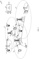
- the wireless communication system 100 may include a plurality of access points 105 (e.g ., base stations, eNBs, or Wi-Fi access points), a number of mobile devices 115, and a core network 130. Some of the access points 105 may communicate with the mobile devices 115 under the control of a base station controller (not shown), which may be part of the core network 130 or certain access points 105 ( e.g ., base stations or eNBs) in various embodiments. Some of the access points 105 may communicate control information and/or user data with the core network 130 through backhaul 132.
- a base station controller not shown
- certain access points 105 e.g ., base stations or eNBs
- Some of the access points 105 may communicate control information and/or user data with the core network 130 through backhaul 132.
- some of the access points 105 may communicate, either directly or indirectly, with each other over backhaul links 134, which may be wired or wireless communication links.
- the wireless communication system 100 may support operation on multiple carriers (e.g ., waveform signals of different frequencies).
- Multi-carrier transmitters may transmit modulated signals simultaneously on the multiple carriers.
- each communication link 125 may be a multi-carrier signal modulated according to various radio technologies.
- Each modulated signal may be sent on a different carrier and may carry control information (e.g ., reference signals, control channels, etc.), overhead information, data, etc.
- the access points 105 may wirelessly communicate with the mobile devices 115 via one or more access point antennas. Each of the access points 105 may provide communication coverage for a respective coverage area 110.
- an access point 105 may be referred to as a base station, a base transceiver station (BTS), a radio base station, a radio transceiver, a basic service set (BSS), an extended service set (ESS), a NodeB, an evolved NodeB (eNB), a Home NodeB, a Home eNodeB, a WLAN access point, or some other suitable terminology.
- the coverage area 110 for an access point 105 may be divided into sectors making up only a portion of the coverage area (not shown).
- the wireless communication system 100 may include access points 105 of different types (e.g ., macro, micro, and/or pico base stations).
- the access points 105 may also utilize different radio technologies and/or may be associated with the same or different access networks.
- the coverage areas of different access points 105, including the coverage areas of the same or different types of access points 105, utilizing the same or different radio technologies, and/or belonging to the same or different access networks, may overlap.
- a macro cell may generally cover a relatively large geographic area (e.g ., several kilometers in radius) and may allow unrestricted access by UEs with service subscriptions with the network provider.
- a pico cell may generally cover a relatively smaller geographic area and may allow unrestricted access by UEs with service subscriptions with the network provider.
- a femto cell may also generally cover a relatively small geographic area (e.g ., a home) and, in addition to unrestricted access, may also provide restricted access by UEs having an association with the femto cell (e.g ., UEs in a closed subscriber group (CSG), UEs for users in the home, and the like).
- CSG closed subscriber group
- An eNB for a macro cell may be referred to as a macro eNB.
- An eNB for a pico cell may be referred to as a pico eNB.
- an eNB for a femto cell may be referred to as a femto eNB or a home eNB.
- An eNB may support one or multiple ( e.g ., two, three, four, and the like) cells.
- the mobile devices 115 may be dispersed throughout the wireless communication system 100.
- a mobile device 115 may also be referred to by those skilled in the art as a user equipment (UE), a mobile station, a subscriber station, a mobile unit, a subscriber unit, a wireless unit, a remote unit, a wireless device, a wireless communication device, a remote device, a mobile subscriber station, an access terminal, a mobile terminal, a wireless terminal, a remote terminal, a handset, a user agent, a mobile client, a client, or some other suitable terminology.
- UE user equipment
- a mobile device 115 may, in some cases, be or include a cellular device (e.g., a smartphone), a computer (e.g., a tablet computer), a wearable device (e.g., a watch or electronic glasses), a module or assembly associated with a vehicle or robotic machine ( e.g ., a module or assembly associated with a forklift or vacuum cleaner), etc.
- a mobile device 115 may be able to communicate with macro eNBs, pico eNBs, femto eNBs, relays, and the like.
- a mobile device 115 may also be able to communicate over different access networks, such as other cellular or WWAN networks, or WLAN access networks (e.g ., Wi-Fi networks).
- the communication links 125 shown in wireless communication system 100 may include uplinks for carrying uplink (UL) transmissions (e.g ., from a mobile device 115 to an access point 105) and/or downlinks for carrying downlink (DL) transmissions (e.g ., from an access point 105 to a mobile device 115).
- UL uplink
- DL downlink
- the UL transmissions may also be called reverse link transmissions, while the DL transmissions may also be called forward link transmissions.
- a mobile device 115 may include an image sensor capable of capturing an image, as described below, for example, with reference to FIG. 2 .
- the mobile device 115 may obtain the electronically stored information and/or offload processing by communicating with one or more devices (e.g., an access point 105) of a wireless communication system such as the wireless communication system 100.
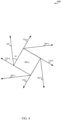
- a diagram 200 illustrates an example of a mobile device 115-a positioned below a number of square or rectangular light fixtures 205-a, 205-b, 205-c, 205-d, 205-e, and 205-f.
- the mobile device 115-a is a wireless communication device a cellular device (e.g., a smartphone), a computer ( e.g., a tablet computer), a wearable device (e.g., a watch or electronic glasses), or robotic machine ( e.g ., a module or assembly associated with a forklift or vacuum cleaner), etc.
- the mobile device 115-a may be an example of the mobile devices 115 illustrated in FIG.
- the light fixtures 205-a, 205-b, 205-c, 205-d, 205-e, and 205-f in some examples are overhead light fixtures in a building, which overhead light fixtures may have fixed orientations with respect to a common reference axis shared by the light fixtures 205-a, 205-b, 205-c, 205-d, 205-e, and 205-f and the mobile device 115-a.
- the common reference axis may be a meridian passing through magnetic north 220.
- the mobile device 115-a includes an image sensor (e.g., a camera of the mobile device 115-a). As the mobile device 115-a moves (or is moved) under one or more of the light fixtures 205-a, 205-b, 205-c, 205-d, 205-e, and 205-f, the image sensor of the mobile device 115-a captures an image of part or all of one or more of the light fixtures 205-a, 205-b, 205-c, 205-d, 205-e, and 205-f.
- the captured image includes an illuminated reference axis, such as the illuminated edge 220 of the light fixture 205-f.
- the mobile device 115-a Upon capturing an image including the illuminated reference axis, the mobile device 115-a determines a first angle, between the illuminated reference axis and a device reference axis of the mobile device 115-a.
- the device reference axis may in some cases correspond to a side of the image sensor, a side of a screen of the mobile device 115-a, or a side of the mobile device 115-a.
- the mobile device 115-a also determines a second angle, between the illuminated reference axis and the common reference axis.
- the mobile device 115-a also estimates a third angle, between the device reference axis and the common reference axis, the common reference axis corresponding to a compass heading.
- the third angle may be estimated, in some cases, by acquiring a compass reading of the mobile device 115-a (e.g., a reading captured using a compass on-board the mobile device 115-a), and estimating the third angle based at least in part on the compass reading.
- a compass reading of the mobile device 115-a e.g., a reading captured using a compass on-board the mobile device 115-a
- the mobile device 115-a may determine its orientation in an X-Y plane. For example, the mobile device 115-a may determine, from at least the first angle and the second angle, a set of at least two possible orientations of the mobile device 115-a.
- the set of at least two possible orientations of the mobile device 115-a may include two possible orientations of the mobile device 115-a (assuming, that is, that the mobile device 115-a can determine whether the illuminated reference axis is a long edge or a short edge of the rectangular light fixture).
- the set of at least two possible orientations of the mobile device 115-a may include four possible orientations of the mobile device 115-a.
- the mobile device 115-a may select its orientation, from the set of at least two possible orientations, based at least in part on the third angle.
- the third angle e.g ., an angle based on a compass reading that may be somewhat imprecise because of the effects of magnetic influences inside a building or other structure
- the third angle may be used to select a more precise orientation of the mobile device 115-a from a set of at least two possible orientations of the mobile device 115-a (wherein the at least two possible orientations are based at least in part on known orientations of the light fixtures 205-a, 205-b, 205-c, 205-d, 205-e, and 205-f).
- some or all of the determinations indicated to be made by the mobile device 115-a may be made remote from the mobile device 115-a and communicated to the mobile device 115-a.
- the orientation may be used for navigation.
- one or more applications running on-board (or remote from) the mobile device 115-a may instruct a user of the mobile device 115-a on where to look and/or how to move to locate a location and/or object.
- the one or more applications may also or alternately cause a control system to move the mobile device 115-a to the location and/or object.
- the image 305 of the at least one illuminated object may be captured using an image sensor 320 of the mobile device 115-b.
- the device reference axis 315 may in some cases correspond to a side of the image sensor 320. Alternately, the device reference axis may correspond to, for example, a side of a screen of the mobile device 115-b, or a side of the mobile device 115-b.
- FIG. 4 illustrates an example 400 of determining a second angle, M, between an illuminated reference axis 310-a of at least one illuminated object 305-a and a common reference axis 405, the common reference axis corresponding to a compass heading (e.g ., a meridian passing through magnetic north).
- the at least one illuminated object 305-a is at least one overhead light fixture ( e.g., one of the light fixtures 205-a, 205-b, 205-c, 205-d, 205-e, and/or 205-f described with reference to Fig 2 ).
- the illuminated reference axis 310-a may be or include an illuminated edge of a polygonal light fixture or light bulb, an illuminated edge of a light fixture or light bulb having an illuminated edge, a line segment defined by a light rope, and/or a line segment defined by at least two illuminated points.
- the at least one illuminated object 305-a is shown in FIG. 4 to be a square light fixture, and the illuminated reference axis 310-a is shown to be an illuminated edge of the square light fixture.
- a mobile device 115 captures an image of the at least one illuminated object 305-a.
- the image includes an image of the illuminated reference axis 310-a.
- a number of illuminated reference axes e.g ., illuminated reference axis 310-a, 310-b, 310-c, or 310-d
- the mobile device 115 captured, and ambiguity regarding the illuminated reference axis 310-a, 310-b, 310-c, or 310-d to which the second angle, M, applies.
- a mobile device 115 can determine whether an illuminated reference axis corresponds to the long edge or the short edge of the rectangular light fixture (and the second angle may be indexed based on its correspondence to the long edge or the short edge), there are two illuminated reference axes to which the second angle may apply.
- FIG. 5 illustrates an example of estimating a third angle, X, between a device reference axis 315-a of a mobile device 115-c and a common reference axis 505, which corresponds to a compass heading (e.g., a meridian passing through magnetic north).
- the determination of the third angle may be based at least in part on a compass reading acquired by a compass of the mobile device 115-c.
- the estimation of the third angle may in some cases be somewhat imprecise, because, for example, of the effects of magnetic influences inside a building or other structure.
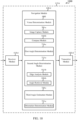
- a block diagram 600 illustrates an example of a mobile device 115-d capable of determining its orientation.
- the mobile device 115-d may be an example of one or more aspects of one of the mobile devices 115 described with reference to FIG. 1 , 2 , 3 , and/or 5.
- the mobile device 115-d is a wireless communication device and is a cellular device (e.g., a smartphone), a computer (e.g., a tablet computer), a wearable device (e.g., a watch or electronic glasses), or robotic machine (e.g., a module or assembly associated with a forklift or vacuum cleaner), etc.
- the mobile device 115-d may include a receiver module 610, a navigation module 620, and/or a transmitter module 630. Each of these components may be in communication with each other.
- the receiver module 610 may include an image sensor (e.g., an image sensor of a camera).
- the image sensor may be used to receive an image of at least one illuminated object, such as an image of a light fixture, a light bulb, a light rope, and/or other form of illuminated object.
- the image sensor may also be used to receive one or more VLC signals (e.g., a VLC signal received from an illuminated object acting as a VLC transmitter and/or a VLC transmitter associated with an illuminated object (e.g., an LED)).
- the receiver module 610 may also or alternately include a VLC receiver (e.g., a photodiode) that is separate from the image sensor.
- the receiver module 610 may also include a radio frequency (RF) receiver, such as a wireless wide area network (WWAN) receiver (e.g ., a cellular receiver and/or LTE/LTE-A receiver), a wireless local area network (WLAN) receiver ( e . g ., a Wi-Fi receiver), a Bluetooth (BT) receiver, and/or a BT Low Energy (BTLE) receiver.
- RF radio frequency
- WWAN wireless wide area network
- WLAN wireless local area network
- BT Bluetooth
- BTLE BT Low Energy
- the RF receiver may be used to receive various types of data and/or control signals (i.e ., transmissions) over one or more RF communication channels of a wireless communication system such as the wireless communication system 100 described with reference to FIG. 1 .
- the transmitter module 630 may include an RF transmitter, such as a WWAN transmitter (e.g ., a cellular transmitter and/or LTE/LTE-A transmitter), a WLAN transmitter, ( e.g ., Wi-Fi transmitter), a BT transmitter, and/or a BTLE transmitter.
- the RF transmitter may be used to transmit various types of data and/or control signals (i.e ., transmissions) over one or more RF communication channels of a wireless communication system such as the wireless communication system 100 described with reference to FIG. 1 .
- the RF receiver(s) of the receiver module 610 and the RF transmitter(s) of the transmitter module 630 may be provided by a WWAN radio (e.g ., a cellular radio and/or LTE/LTE-A radio) and/or a WLAN radio (e.g., a Wi-Fi radio).
- a WWAN radio e.g ., a cellular radio and/or LTE/LTE-A radio
- a WLAN radio e.g., a Wi-Fi radio
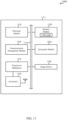
- a block diagram 700 illustrates an example of a mobile device 115-e capable of determining its orientation.
- the mobile device 115-e may be an example of one or more aspects of one of the mobile devices 115 described with reference to FIG. 1 , 2 , 3 , 5 , and/or 6.
- the mobile device 115-e is a wireless communications device and is a cellular device (e.g., a smartphone), a computer (e.g., a tablet computer), a wearable device (e.g., a watch or electronic glasses), or robotic machine ( e.g ., a module or assembly associated with a forklift or vacuum cleaner), etc.
- the mobile device 115-e may include a receiver module 610-a, a navigation module 620-a, and/or a transmitter module 630-a. Each of these components may be in communication with each other.
- the navigation module 620-a may perform various functions.
- the navigation module 620-a may be an example of the navigation module 620 described with reference to FIG. 6 .
- the navigation module 620-a may include an image capture module 705, a first angle determination module 710, a second angle determination module 715, a third angle estimation module 720, and/or an orientation determination module 725.
- the image capture module 705 is used to capture an image of at least one illuminated object defining an illuminated reference axis.
- the image of the at least one illuminated object is an image of at least part of at least one overhead light fixture.
- the illuminated reference axis may be or include an illuminated edge of a polygonal light fixture or light bulb, an illuminated edge of a light fixture or light bulb having an illuminated edge, a line segment defined by a light rope, and/or a line segment defined by at least two illuminated points.
- the first angle determination module 710 may be used to determine a first angle, between the illuminated reference axis and a device reference axis of the mobile device 115-e.
- the device reference axis may in some cases correspond to a side of an image sensor (e.g., a side of an image sensor that captures the image of the at least one illuminated object), a side of a screen of the mobile device 115-e, or a side of the mobile device 115-e.
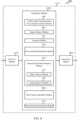
- a block diagram 800 illustrates an example of a mobile device 115-f capable of determining its orientation.
- the mobile device 115-f may be an example of one or more aspects of one of the mobile devices 115 described with reference to FIG. 1 , 2 , 3 , 5 , 6 , and/or 7.
- the mobile device 115-f is included in a cellular device (e.g., a smartphone), a computer (e.g., a tablet computer), a wearable device (e.g., a watch or electronic glasses), or robotic machine (e.g., a module or assembly associated with a forklift or vacuum cleaner), etc.
- the mobile device 115-f may include a receiver module 610-b, a navigation module 620-b, and/or a transmitter module 630-b. Each of these components may be in communication with each other.
- the navigation module 620-b may perform various functions.
- the navigation module 620-b may be an example of the navigation module 620 described with reference to FIG. 6 and/or 7.
- the navigation module 620-b may include a VLC signal analysis module 805, an image capture module 705-a, a compass module 810, a first angle determination module 710-a, a second angle determination module 715-a, a third angle estimation module 720-a, and/or an orientation determination module 725-a.
- the VLC signal analysis module 805 may be used to receive a VLC signal including an identifier of an illuminated object.
- the VLC signal analysis module 805 may receive the VLC signal from an illuminated object acting as a VLC transmitter and/or from a VLC transmitter associated with an illuminated object (e.g., an LED).
- the VLC signal analysis module 805 may decode the VLC signal to extract the identifier of the illuminated object.
- the image capture module 705-a may be an example of the image capture module 705 described with reference to FIG. 7 .
- the image capture module 705-a may be used to capture an image of at least one illuminated object defining an illuminated reference axis.
- the at least one illuminated object may include an illuminated object identified by a VLC signal received by the VLC signal analysis module 805.
- the at least one illuminated object is a light fixture.
- the image of the at least one illuminated object may include an image of at least part of at least one overhead light fixture.
- the illuminated reference axis may be or include an illuminated edge of a polygonal light fixture or light bulb, an illuminated edge of a light fixture or light bulb having an illuminated edge, a line segment defined by a light rope, and/or a line segment defined by at least two illuminated points.
- An example of the operation(s) performed by the image capture module 705-a and/or the first angle determination module 710-a is described with reference to FIG. 3 .
- An example of the operation(s) performed by the compass module 810 is described with reference to FIG. 5 .
- the second angle determination module 715-a may be an example of the second angle determination module 715 described with reference to FIG. 7 .
- the second angle determination module 715-a may be used to determine a second angle, between the illuminated reference axis and a common reference axis, based at least in part on an identifier of an illuminated object received by the VLC signal analysis module 805 (and optionally, based at least in part on a relative length of an edge identified by the edge analysis module 815).
- the common reference axis corresponds to a compass heading (e.g., a meridian passing through magnetic north).
- the second angle determination module 715-a may include an edge analysis module 815 and an angle retrieval module 820.
- the edge analysis module 815 may be used to identify an edge of at least one illuminated object in an image captured by the image capture module 705-a.
- the edge analysis module 815 may also be used to determine a relative length of the edge.
- the relative length of the edge may be a length of the edge relative to another feature (e.g., another edge) of at least one illuminated object in an image captured by the image capture module 705-a.
- the determined relative length of the edge may include an indication of whether the edge is the long edge or the short edge of a rectangular light fixture.
- the edge identified by the edge analysis module 815 may in some cases be an edge that defines the illuminated reference axis of an image captured by the image capture module 705-a.
- the angle retrieval module 820 may be used to obtain the second angle from electronically stored information (e.g., an electronically stored map and/or database). In some examples, the angle retrieval module 820 may use an identifier of an illuminated object received by the VLC signal analysis module 805 to retrieve, e.g., from electronically stored information, a second angle corresponding to the identified illuminated object.
- electronically stored information e.g., an electronically stored map and/or database
- the angle retrieval module 820 may use an identifier of an illuminated object received by the VLC signal analysis module 805 to retrieve, e.g., from electronically stored information, a second angle corresponding to the identified illuminated object.
- the angle retrieval module 820 may use an identifier of an illuminated object received by the VLC signal analysis module 805, in conjunction with a determined relative length of an edge of at least one illuminated object in an image captured by the image capture module 705-a, to retrieve, e.g., from electronically stored information, a second angle corresponding to both the identified illuminated object and the identified edge.
- obtaining the second angle from electronically stored information may include accessing the electronically stored information over a network (e.g., a cellular network or a Wi-Fi network), while in some examples, obtaining the second angle from electronically stored information may include accessing the electronically stored information on the mobile device 115-f.
- the electronically stored information may correspond to a building or other venue, and may be downloaded to the mobile device 115-f upon entering or nearing the venue.
- the third angle estimation module 720-a may be an example of the third angle estimation module 720 described with reference to FIG. 7 . In some examples, the third angle estimation module 720-a may be used to estimate a third angle, between the device reference axis and the common reference axis, based at least in part on a compass reading acquired by the compass module 810.
- the orientation determination module 725-a may be an example of the orientation determination module 725 described with reference to FIG. 7 .
- the orientation determination module 725-a may be used to determine an orientation of the mobile device 115-f based at least in part on the first angle, the second angle, and the third angle. More particularly, and in some examples, the orientation determination module 725-a may determine, from at least the first angle and the second angle, a set of at least two possible orientations of the mobile device 115-f.
- the set of at least two possible orientations of the mobile device 115-f may include two possible orientations of the mobile device 115-f.
- the set of at least two possible orientations of the mobile device 115-f may include four possible orientations of the mobile device 115-f.
- the orientation determination module 725-a may select the orientation of the mobile device 115-f, from the set of at least two possible orientations of the mobile device 115-f, based at least in part on the third angle estimated by the third angle estimation module 720-a.
- the third angle e.g., an angle based on a compass reading that may be somewhat imprecise because of the effects of magnetic influences inside a building or other structure
- the third angle may be used to select a more precise orientation of the mobile device 115-f from a set of at least two possible orientations of the mobile device 115-f.
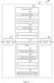
- a block diagram 900 illustrates an example of a mobile device 115-g capable of determining its orientation.
- the mobile device 115-g may be an example of one or more aspects of one of the mobile devices 115 described with reference to FIG. 1 , 2 , 3 , 5 , 6 , and/or 7.
- the mobile device 115-g is a wireless communcation device and is a cellular device (e.g., a smartphone), a computer (e.g., a tablet computer), a wearable device (e.g., a watch or electronic glasses), or robotic machine (e.g., a module or assembly associated with a forklift or vacuum cleaner), etc.
- the mobile device 115-g may include a receiver module 610-c, a navigation module 620-c, and/or a transmitter module 630-c. Each of these components may be in communication with each other.
- the receiver module 610-c and/or the transmitter module 630-c may in some cases be configured similarly to the receiver module 610 and/or the transmitter module 630 described with reference to FIG. 6 .
- the navigation module 620-c may perform various functions.
- the navigation module 620-c may be an example of the navigation module 620 described with reference to FIG. 6 and/or 7.
- the navigation module 620-c may include an image capture module 705-b, an object identification module 905, a compass module 810-a, a first angle determination module 710-b, a second angle determination module 715-b, a third angle estimation module 720-b, and/or an orientation determination module 725-b.
- the image capture module 705-b may be an example of the image capture module 705 described with reference to FIG. 7 .
- the image capture module 705-b may be used to capture an image of at least one illuminated object defining an illuminated reference axis.
- the at least one illuminated object is a light fixture.
- the image of the at least one illuminated object includes least part of at least one overhead light fixture.
- the illuminated reference axis may be or include an illuminated edge of a polygonal light fixture or light bulb, an illuminated edge of a light fixture or light bulb having an illuminated edge, a line segment defined by a light rope, and/or a line segment defined by at least two illuminated points.
- the object identification module 905 may be used determine, from the image of the at least one illuminated object, a visual identifier of an illuminated object in the image.
- the visual identifier may include a visually illuminated indicia on the illuminated object, such as a unique or quasi-unique pattern of light and dark elements, color, and/or pattern of colored elements.
- the compass module 810-a may be used to acquire a compass reading of the mobile device 115-g (e.g., from a compass of the mobile device 115-g).
- An example of the operation(s) performed by the image capture module 705-b and/or the first angle determination module 710-b is described with reference to FIG. 3 .
- An example of the operation(s) performed by the compass module 810-a is described with reference to FIG. 5 .
- the second angle determination module 715-b may be an example of the second angle determination module 715 described with reference to FIG. 7 .
- the second angle determination module 715-b may be used to determine a second angle, between the illuminated reference axis and a common reference axis, based at least in part on a visual identifier of an illuminated object determined by the object identification module 905 (and optionally, based at least in part on a relative length of an edge identified by an edge analysis module 815-a).
- the common reference axis may correspond to a compass heading (e.g., a meridian passing through magnetic north).
- the second angle determination module 715-b may include the edge analysis module 815-a and an angle retrieval module 820-a.
- the edge analysis module 815-a may be used to identify an edge of at least one illuminated object in an image captured by the image capture module 705-b.
- the edge analysis module 815-a may also be used to determine a relative length of the edge.
- the relative length of the edge may be a length of the edge relative to another feature (e.g., another edge) of at least one illuminated object in an image captured by the image capture module 705-b.
- the determined relative length of the edge may include an indication of whether the edge is the long edge or the short edge of a rectangular light fixture.
- the edge identified by the edge analysis module 815-a may, in some cases, be an edge that defines the illuminated reference axis of an image captured by the image capture module 705-b.
- the angle retrieval module 820-a may be used to obtain the second angle from electronically stored information (e.g., an electronically stored map and/or database). In some examples, the angle retrieval module 820-a may use a visual identifier of an illuminated object determined by the object identification module 905 to retrieve, e.g., from electronically stored information, a second angle corresponding to the visually identified illuminated object.
- electronically stored information e.g., an electronically stored map and/or database
- the angle retrieval module 820-a may use a visual identifier of an illuminated object determined by the object identification module 905 to retrieve, e.g., from electronically stored information, a second angle corresponding to the visually identified illuminated object.
- the angle retrieval module 820-a may use a visual identifier of an illuminated object determined by the object identification module 905, in conjunction with a determined relative length of an edge of at least one illuminated object in an image captured by the image capture module 705-b, to retrieve, e.g., from electronically stored information, a second angle corresponding to both the visually identified illuminated object and the identified edge.
- obtaining the second angle from electronically stored information may include accessing the electronically stored information over a network (e.g., a cellular network or a Wi-Fi network), while in some examples, obtaining the second angle from electronically stored information may include accessing the electronically stored information on the mobile device 115-g.
- the electronically stored information may correspond to a building or other venue, and may be downloaded to the mobile device 115-g upon entering or nearing the venue.
- the third angle estimation module 720-b may be an example of the third angle estimation module 720 described with reference to FIG. 7 . In some examples, the third angle estimation module 720-b may be used to estimate a third angle, between the device reference axis and the common reference axis, based at least in part on a compass reading acquired by the compass module 810-a.
- the orientation determination module 725-b may be an example of the orientation determination module 725 described with reference to FIG. 7 .
- the orientation determination module 725-b may be used to determine an orientation of the mobile device 115-g based at least in part on the first angle, the second angle, and the third angle. More particularly, and in some examples, the orientation determination module 725-b may determine, from at least the first angle and the second angle, a set of at least two possible orientations of the mobile device 115-g.
- the set of at least two possible orientations of the mobile device 115-g may include two possible orientations of the mobile device 115-g.
- the set of at least two possible orientations of the mobile device 115-g may include four possible orientations of the mobile device 115-g.
- a block diagram 1000 illustrates an example of a mobile device 115-h capable of determining its orientation.
- the mobile device 115-h may be an example of one or more aspects of one of the mobile devices 115 described with reference to FIG. 1 , 2 , 3 , 5 , 6 , and/or 7.
- the mobile device 115-h is a mobile communication device and is a cellular device (e.g., a smartphone), a computer (e.g., a tablet computer), a wearable device (e.g., a watch or electronic glasses), a module or assembly associated with a vehicle or robotic machine (e.g., a module or assembly associated with a forklift or vacuum cleaner), etc.
- the mobile device 115-h may include a receiver module 610-d, a navigation module 620-d, and/or a transmitter module 630-d. Each of these components may be in communication with each other.
- the venue determination module 1005 may be used to determine a venue in which the mobile device 115-h is located (e.g., a building or other structure in which the mobile device 115-h is located). In some examples, the venue may be determined based on global positioning system (GPS) signals or the identity of a Wi-Fi network accessible to the mobile device 115-h.
- GPS global positioning system
- the compass module 810-b may be used to acquire a compass reading of the mobile device 115-h (e.g., from a compass of the mobile device 115-h).
- the first angle determination module 710-c may be an example of the first angle determination module 710 described with reference to FIG. 7 . In some examples, the first angle determination module 710-c may be used to determine a first angle, between the illuminated reference axis and a device reference axis of the mobile device 115-h.
- the device reference axis may in some cases correspond to a side of an image sensor (e.g., a side of an image sensor that captures the image of the at least one illuminated object), a side of a screen of the mobile device 115-h, or a side of the mobile device 115-h.
- the second angle determination module 715-c may be an example of the second angle determination module 715 described with reference to FIG. 7 .
- the second angle determination module 715-c may be used to determine a second angle, between the illuminated reference axis and a common reference axis, based at least in part on the venue of the mobile device 115-h (and optionally, based at least in part on a relative length of an edge identified by an edge analysis module 815-b).
- the common reference axis may correspond to a compass heading (e.g., a meridian passing through magnetic north).
- the third angle estimation module 720-c may be an example of the third angle estimation module 720 described with reference to FIG. 7 . In some examples, the third angle estimation module 720-c may be used to estimate a third angle, between the device reference axis and the common reference axis, based at least in part on a compass reading acquired by the compass module 810-b.
- the orientation determination module 725-c may be an example of the orientation determination module 725 described with reference to FIG. 7 .
- the orientation determination module 725-c may be used to determine an orientation of the mobile device 115-h based at least in part on the first angle, the second angle, and the third angle. More particularly, and in some examples, the orientation determination module 725-c may determine, from at least the first angle and the second angle, a set of at least two possible orientations of the mobile device 115-h.
- the set of at least two possible orientations of the mobile device 115-h may include two possible orientations of the mobile device 115-h.
- the set of at least two possible orientations of the mobile device 115-h may include four possible orientations of the mobile device 115-h.
- the orientation determination module 725-c may select the orientation of the mobile device 115-h, from the set of at least two possible orientations of the mobile device 115-h, based at least in part on the third angle estimated by the third angle estimation module 720-c.
- the third angle e.g., an angle based on a compass reading that may be somewhat imprecise because of the effects of magnetic influences inside a building or other structure
- the third angle may be used to select a more precise orientation of the mobile device 115-h from a set of at least two possible orientations of the mobile device 115-h.
- FIG. 11 is a block diagram 1100 illustrating an example of a mobile device 115-i capable of determining its orientation.
- the mobile device 115-i may be an example of one or more aspects of one of the mobile devices 115 described with reference to FIG. 1 , 2 , 3 , 5 , 6 , 7 , 8 , 9 , and/or 10.
- the mobile device 115-i is a wireless communication device and is a cellular device (e.g., a smartphone), a computer (e.g., a tablet computer), a wearable device (e.g., a watch or electronic glasses), or robotic machine (e.g., a module or assembly associated with a forklift or vacuum cleaner), etc.
- the mobile device 115-i may have an internal power supply (not shown), such as a small battery, to facilitate mobile operation.
- the memory module 1120 may include random access memory (RAM) and/or read-only memory (ROM).
- the memory module 1120 may store computer-readable, computer-executable code 1125 containing instructions that are configured to, when executed, cause the processor module 1110 to perform various functions described herein for connecting to and/or configuring one or more other devices.
- the code 1125 may not be directly executable by the processor module 1110 but be configured to cause the mobile device 115-i (e.g., when compiled and executed) to perform various of the functions described herein.
- the processor module 1110 may include an intelligent hardware device, e.g., a CPU, such as an ARM ® based processor or those made by Intel ® Corporation or AMD ® , a microcontroller, an ASIC, etc.
- the processor module 1110 may process information received through the transceiver module(s) 1130 and/or image sensor 1160, as well as information to be sent to the transceiver module(s) 1130 for transmission via the antenna(s) 1140.
- the processor module 1110 may handle, alone or in connection with the navigation module 620-e, various aspects pertaining to device navigation, including, for example, the determination of an orientation of the mobile device 115-i.
- the image sensor 1160 may in some cases include a complimentary metal-oxide semiconductor (CMOS) image sensor.
- CMOS complimentary metal-oxide semiconductor
- the image sensor 1160 may receive light emitted from one or more illuminated objects and/or one or more VLC transmitters.
- the mobile device 115-i may also include an ambient light sensor, such as an ambient light sensor including one or more photodiodes capable of detecting VLC signals transmitted by VLC transmitters.
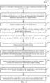
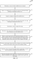
- FIG. 12 is a flow chart illustrating a method 1200 for determining an orientation of a mobile device.
- the method 1200 is described below with reference to aspects of one or more of the mobile devices 115 described with reference to FIG. 1 , 2 , 3 , 5 , 6 , 7 , 8 , 9 , 10 , and/or 11.
- the navigation module 620 described with reference to FIG. 6 , 7 , 8 , 9 , 10 , and/or 11 may execute one or more sets of codes to control the functional elements of a mobile device 115 to perform the functions described below.
- the method 1200 includes capturing, at a mobile device 115, an image of at least one illuminated object defining an illuminated reference axis.
- the mobile device 115 is a wireless communication device and is a cellular device (e.g., a smartphone), a computer (e.g., a tablet computer), a wearable device (e.g., a watch or electronic glasses), or robotic machine (e.g., a module or assembly associated with a forklift or vacuum cleaner), etc.
- Capturing the image of the at least one illuminated object includes capturing an image of at least part of at least one overhead light fixture.
- the method 1200 may be used for wireless communication. It should be noted that the method 1200 is just one implementation and that the operations of the method 1200 may be rearranged or otherwise modified such that other implementations are possible.
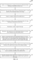
- the method 1300 includes capturing, at a mobile device 115, an image of at least one illuminated object defining an illuminated reference axis.
- the at least one illuminated object may include the illuminated object identified by the VLC signal received at block 1305.
- the mobile device 115 is a wireless communication device and is a cellular device (e.g., a smartphone), a computer (e.g., a tablet computer), a wearable device (e.g., a watch or electronic glasses), or robotic machine (e.g., a module or assembly associated with a forklift or vacuum cleaner), etc.
- Capturing the image of the at least one illuminated object includes capturing an image of at least part of at least one overhead light fixture.
- the method 1300 include determining an orientation of the mobile device 115 based at least in part on the first angle, the second angle, and the third angle. More particularly, and at block 1345, the method 1300 may include determining, from at least the first angle and the second angle, a set of at least two possible orientations of the mobile device.
- the at least one illuminated object includes a rectangular light fixture and the illuminated reference axis includes an edge of the rectangular light fixture
- the set of at least two possible orientations of the mobile device may include two possible orientations of the mobile device.
- the set of at least two possible orientations of the mobile device may include four possible orientations of the mobile device.
- the method may include selecting the orientation of the mobile device, from the set of at least two possible orientations of the mobile device, based at least in part on the third angle.
- the third angle e.g., an angle based on a compass reading that may be somewhat imprecise because of the effects of magnetic influences inside a building or other structure
- the third angle may be used to select a more precise orientation of the mobile device from a set of at least two possible orientations of the mobile device.
- capturing the image of the at least one illuminated object may include capturing an image of at least part of at least one overhead light fixture.
- the illuminated reference axis may be or include an illuminated edge of a polygonal light fixture or light bulb, an illuminated edge of a light fixture or light bulb having an illuminated edge, a line segment defined by a light rope, and/or a line segment defined by at least two illuminated points.
- the operation(s) at block 1405 may be performed and/or managed using the navigation module 620 described with reference to FIG. 6 , 7 , 8 , 9 , 10 , and/or 11, and/or the image capture module 705 described with reference to FIG. 7 , 8 , 9 , and/or 10. An example of the operation(s) performed at block 1405 is described with reference to FIG. 3 .
- the method 1400 may include determining, from the image of the at least one illuminated object, a visual identifier of an illuminated object in the image.
- the visual identifier may include a visually illuminated indicia on the illuminated object, such as a unique or quasi-unique pattern of light and dark elements, color, and/or pattern of colored elements.
- the operation(s) at block 1410 may be performed and/or managed using the navigation module 620 described with reference to FIG. 6 , 7 , 8 , 9 , 10 , and/or 11, and/or the object identification module 905 described with reference to FIG. 9 .
- the method 1400 may include acquiring a compass reading of the mobile device 115 (e.g., from a compass of the mobile device 115).
- the operation(s) at block 1415 may be performed and/or managed using the navigation module 620 described with reference to FIG. 6 , 7 , 8 , 9 , 10 , and/or 11, and/or the compass module 810 described with reference to FIG. 8 .
- An example of the operation(s) performed at block 1415 is described with reference to FIG. 5 .
- the method 1400 may include identifying an edge of one of the at least one illuminated object.
- the edge may define the illuminated reference axis.
- the method 1400 may include determining a relative length of the edge.
- the relative length of the edge may be a length of the edge relative to another feature (e.g., another edge) of the at least one illuminated object in the image of the at least one illuminated object.
- the determined relative length of the edge may include an indication of whether the edge is the long edge or the short edge of a rectangular light fixture.
- the operation(s) at block 1420 and/or block 1425 may be performed and/or managed using the navigation module 620 described with reference to FIG.
- the method 1400 may include determining a first angle, between the illuminated reference axis and a device reference axis of the mobile device 115.
- the device reference axis may in some cases correspond to a side of an image sensor (e.g., a side of an image sensor that captures the image of the at least one illuminated object), a side of a screen of the mobile device 115, or a side of the mobile device 115.
- the operation(s) at block 1430 may be performed and/or managed using the navigation module 620 described with reference to FIG. 6 , 7 , 8 , 9 , 10 , and/or 11, and/or the first angle determination module 710 described with reference to FIG. 7 , 8 , 9 , and/or 10. An example of the operation(s) performed at block 1430 is described with reference to FIG. 3 .
- the method 1400 may include determining a second angle, between the illuminated reference axis and a common reference axis, based at least in part on the visual identifier of the illuminated object determined at block 1410 (and optionally, based at least in part on the relative length of the edge identified at block 1420).
- the visual identifier of the illuminated object may be used to retrieve, e.g., from electronically stored information, a second angle corresponding to the identified illuminated object.
- the visual identifier of the illuminated object and the relative length of the edge may be used to retrieve, e.g., from electronically stored information, a second angle corresponding to both the visually identified illuminated object and the identified edge.
- the electronically stored information may include an electronically stored map and/or database.
- obtaining the second angle from electronically stored information may include accessing the electronically stored information over a network (e.g., a cellular network or a Wi-Fi network), while in some examples, obtaining the second angle from electronically stored information may include accessing the electronically stored information on the mobile device 115.
- the electronically stored information may correspond to a building or other venue, and may be downloaded to the mobile device 115 upon entering or nearing the venue.
- the common reference axis may correspond to a compass heading (e.g., a meridian passing through magnetic north).
- the operation(s) at block 1435 may be performed and/or managed using the navigation module 620 described with reference to FIG.
- the method 1400 may include estimating a third angle, between the device reference axis and the common reference axis, based at least in part on the compass reading acquired at block 1415.
- the operation(s) at block 1440 may be performed and/or managed using the navigation module 620 described with reference to FIG. 6 , 7 , 8 , 9 , 10 , and/or 11, and/or the third angle estimation module 720 described with reference to FIG. 7 , 8 , 9 , and/or 10.
- An example of the operation(s) performed at block 1440 is described with reference to FIG. 5 .
- the method 1400 may include determining an orientation of the mobile device 115 based at least in part on the first angle, the second angle, and the third angle. More particularly, and at block 1445, the method 1400 may include determining, from at least the first angle and the second angle, a set of at least two possible orientations of the mobile device.
- the at least one illuminated object includes a rectangular light fixture and the illuminated reference axis includes an edge of the rectangular light fixture
- the set of at least two possible orientations of the mobile device may include two possible orientations of the mobile device.
- the set of at least two possible orientations of the mobile device may include four possible orientations of the mobile device.
- the method may include selecting the orientation of the mobile device, from the set of at least two possible orientations of the mobile device, based at least in part on the third angle.
- the third angle e.g., an angle based on a compass reading that may be somewhat imprecise because of the effects of magnetic influences inside a building or other structure
- the third angle may be used to select a more precise orientation of the mobile device from a set of at least two possible orientations of the mobile device.
- the operation(s) at block 1445 and/or block 1450 may be performed and/or managed using the navigation module 620 described with reference to FIG. 6 , 7 , 8 , 9 , 10 , and/or 11, and/or the orientation determination module 725 described with reference to FIG. 7 , 8 , 9 , and/or 10.
- An example of the operation(s) performed at block 1445 and/or block 1450 is described with reference to FIG. 5 .
- FIG. 15 is a flow chart illustrating a method 1500 for determining an orientation of a mobile device.
- the method 1500 is described below with reference to aspects of one or more of the mobile devices 115 described with reference to FIG. 1 , 2 , 3 , 5 , 6 , 7 , 8 , 9 , 10 , and/or 11.
- the navigation module 620 described with reference to FIG. 6 , 7 , 8 , 9 , 10 , and/or 11 may execute one or more sets of codes to control the functional elements of a mobile device 115 to perform the functions described below.
- the method 1500 may include determining a venue in which a mobile device 115 is located (e.g., a building or other structure in which the mobile device 115 is located).
- the venue may be determined based on global positioning system (GPS) signals or the identity of a Wi-Fi network accessible to the mobile device 115.
- GPS global positioning system
- the operation(s) at block 1505 may be performed and/or managed using the navigation module 620 described with reference to FIG. 6 , 7 , 8 , 9 , 10 , and/or 11, and/or the venue determination module 1005 described with reference to FIG. 10 .
- the method 1500 includes capturing, at a mobile device 115, an image of at least one illuminated object defining an illuminated reference axis.
- the mobile device 115 is a wireless communication device and is a cellular device (e.g., a smartphone), a computer (e.g., a tablet computer), a wearable device ( e . g ., a watch or electronic or robotic machine (e.g., a module or assembly associated with a forklift or vacuum cleaner), etc.
- Capturing the image of the at least one illuminated obj ect includes capturing an image of at least part of at least one overhead light fixture.
- the method 1500 may include acquiring a compass reading of the mobile device 115 (e.g., from a compass of the mobile device 115).
- the operation(s) at block 1515 may be performed and/or managed using the navigation module 620 described with reference to FIG. 6 , 7 , 8 , 9 , 10 , and/or 11, and/or the compass module 810 described with reference to FIG. 8 .
- An example of the operation(s) performed at block 1515 is described with reference to FIG. 5 .
- the method 1500 includes determining a first angle, between the illuminated reference axis and a device reference axis of the mobile device 115.
- the device reference axis may in some cases correspond to a side of an image sensor (e.g., a side of an image sensor that captures the image of the at least one illuminated object), a side of a screen of the mobile device 115, or a side of the mobile device 115.
- the operation(s) at block 1530 may be performed and/or managed using the navigation module 620 described with reference to FIG. 6 , 7 , 8 , 9 , 10 , and/or 11, and/or the first angle determination module 710 described with reference to FIG. 7 , 8 , 9 , and/or 10. An example of the operation(s) performed at block 1530 is described with reference to FIG. 3 .
- the electronically stored information may include an electronically stored map and/or database.
- obtaining the second angle from electronically stored information may include accessing the electronically stored information over a network (e.g., a cellular network or a Wi-Fi network), while in some examples, obtaining the second angle from electronically stored information may include accessing the electronically stored information on the mobile device 115.
- the electronically stored information may correspond to a building or other venue, and may be downloaded to the mobile device 115 upon entering or nearing the venue.
- the common reference axis corresponds to a compass heading (e.g., a meridian passing through magnetic north).
- the operation(s) at block 1535 may be performed and/or managed using the navigation module 620 described with reference to FIG.
- the operation(s) at block 1545 and/or block 1550 may be performed and/or managed using the navigation module 620 described with reference to FIG. 6 , 7 , 8 , 9 , 10 , and/or 11, and/or the orientation determination module 725 described with reference to FIG. 7 , 8 , 9 , and/or 10.
- An example of the operation(s) performed at block 1545 and/or block 1550 is described with reference to FIG. 5 .
- the method 1500 may be used for wireless communication. It should be noted that the method 1500 is just one implementation and that the operations of the method 1500 may be rearranged or otherwise modified such that other implementations are possible.
- aspects of the methods 1200, 1300, 1400, and/or 1500 may be combined.
- a CDMA system may implement a radio technology such as CDMA2000, Universal Terrestrial Radio Access (UTRA), etc.
- CDMA2000 covers IS-2000, IS-95, and IS-856 standards.
- IS-2000 Releases 0 and A are commonly referred to as CDMA2000 1X, 1X, etc.
- IS-856 (TIA-856) is commonly referred to as CDMA2000 1xEV-DO, High Rate Packet Data (HRPD), etc.
- UTRA includes Wideband CDMA (WCDMA) and other variants of CDMA.
- a TDMA system may implement a radio technology such as Global System for Mobile Communications (GSM).
- GSM Global System for Mobile Communications
- An OFDMA system may implement a radio technology such as Ultra Mobile Broadband (UMB), Evolved UTRA (E-UTRA), IEEE 802.11 (Wi-Fi), IEEE 802.16 (WiMAX), IEEE 802.20, Flash-OFDM ⁇ , etc.
- UMB Ultra Mobile Broadband
- E-UTRA Evolved UTRA
- Wi-Fi Wi-Fi
- WiMAX IEEE 802.16
- IEEE 802.20 Flash-OFDM ⁇
- UMB Ultra Mobile Broadband
- E-UTRA Evolved UTRA
- Wi-Fi IEEE 802.11
- WiMAX IEEE 802.16
- Flash-OFDM ⁇ Flash-OFDM ⁇
- UMB Ultra Mobile Broadband
- E-UTRA Evolved UTRA
- Wi-Fi IEEE 802.11
- UTRA, E-UTRA, UMTS, LTE, LTE-A, and GSM are described in documents from an organization named "3rd Generation Partnership Project” (3GPP).
- CDMA2000 and UMB are described in documents from an organization named “3rd Generation Partnership Project 2" (3GPP2).
- the techniques described herein may be used for the systems and radio technologies mentioned above as well as other systems and radio technologies.
- ASICs application-specific integrated circuits
- DSP digital signal processor
- a general-purpose processor may be a microprocessor, any conventional processor, controller, microcontroller, state machine, or combination thereof.
- Disk and disc include compact disc (CD), laser disc, optical disc, digital versatile disc (DVD), floppy disk and Blu-ray disc where disks usually reproduce data magnetically, while discs reproduce data optically with lasers. Combinations of the above are also included within the scope of computer-readable media.
Landscapes
- Engineering & Computer Science (AREA)
- Physics & Mathematics (AREA)
- General Physics & Mathematics (AREA)
- Electromagnetism (AREA)
- Radar, Positioning & Navigation (AREA)
- Remote Sensing (AREA)
- Theoretical Computer Science (AREA)
- Computer Vision & Pattern Recognition (AREA)
- Multimedia (AREA)
- Image Analysis (AREA)
- Optical Communication System (AREA)
- Circuit Arrangement For Electric Light Sources In General (AREA)
- Telephone Function (AREA)
- Length Measuring Devices By Optical Means (AREA)
Applications Claiming Priority (2)
| Application Number | Priority Date | Filing Date | Title |
|---|---|---|---|
| US14/271,202 US9317747B2 (en) | 2014-05-06 | 2014-05-06 | Determining an orientation of a mobile device |
| PCT/US2015/024435 WO2015171232A1 (en) | 2014-05-06 | 2015-04-06 | Determining an orientation of a mobile device |
Publications (2)
| Publication Number | Publication Date |
|---|---|
| EP3140808A1 EP3140808A1 (en) | 2017-03-15 |
| EP3140808B1 true EP3140808B1 (en) | 2023-12-20 |
Family
ID=53005666
Family Applications (1)
| Application Number | Title | Priority Date | Filing Date |
|---|---|---|---|
| EP15718685.9A Active EP3140808B1 (en) | 2014-05-06 | 2015-04-06 | Determining an orientation of a mobile device |
Country Status (6)
| Country | Link |
|---|---|
| US (1) | US9317747B2 (enExample) |
| EP (1) | EP3140808B1 (enExample) |
| JP (1) | JP2017523387A (enExample) |
| KR (1) | KR20170004976A (enExample) |
| CN (1) | CN106415308B (enExample) |
| WO (1) | WO2015171232A1 (enExample) |
Families Citing this family (9)
| Publication number | Priority date | Publication date | Assignee | Title |
|---|---|---|---|---|
| TWI791236B (zh) | 2015-12-30 | 2023-02-01 | 美商艾倫神火公司 | 光學窄播 |
| US20170244482A1 (en) * | 2016-02-24 | 2017-08-24 | Qualcomm Incorporated | Light-based communication processing |
| US9857162B1 (en) | 2016-09-22 | 2018-01-02 | Qualcomm Incorporated | Mobile device positioning using modulated light signals and coarse positioning information |
| US9917652B1 (en) | 2017-06-06 | 2018-03-13 | Surefire Llc | Adaptive communications focal plane array |
| US10473439B2 (en) | 2018-01-05 | 2019-11-12 | Aron Surefire, Llc | Gaming systems and methods using optical narrowcasting |
| US10236986B1 (en) | 2018-01-05 | 2019-03-19 | Aron Surefire, Llc | Systems and methods for tiling free space optical transmissions |
| US10250948B1 (en) | 2018-01-05 | 2019-04-02 | Aron Surefire, Llc | Social media with optical narrowcasting |
| US11115765B2 (en) * | 2019-04-16 | 2021-09-07 | Biamp Systems, LLC | Centrally controlling communication at a venue |
| KR102537614B1 (ko) | 2022-10-25 | 2023-06-01 | 김찬녕 | 다중제어방식의 쐐기식 말뚝재하장치를 이용한 말뚝시공방법 |
Citations (1)
| Publication number | Priority date | Publication date | Assignee | Title |
|---|---|---|---|---|
| US4933864A (en) * | 1988-10-04 | 1990-06-12 | Transitions Research Corporation | Mobile robot navigation employing ceiling light fixtures |
Family Cites Families (19)
| Publication number | Priority date | Publication date | Assignee | Title |
|---|---|---|---|---|
| US5155684A (en) | 1988-10-25 | 1992-10-13 | Tennant Company | Guiding an unmanned vehicle by reference to overhead features |
| WO2001037060A1 (en) | 1999-11-18 | 2001-05-25 | The Procter & Gamble Company | Home cleaning robot |
| US20050213109A1 (en) | 2004-03-29 | 2005-09-29 | Evolution Robotics, Inc. | Sensing device and method for measuring position and orientation relative to multiple light sources |
| US7720554B2 (en) | 2004-03-29 | 2010-05-18 | Evolution Robotics, Inc. | Methods and apparatus for position estimation using reflected light sources |
| US7605702B2 (en) * | 2004-06-25 | 2009-10-20 | Nec Corporation | Article position management system, article position management method, terminal device, server, and article position management program |
| US8381982B2 (en) * | 2005-12-03 | 2013-02-26 | Sky-Trax, Inc. | Method and apparatus for managing and controlling manned and automated utility vehicles |
| WO2008152545A1 (en) * | 2007-06-14 | 2008-12-18 | Koninklijke Philips Electronics N.V. | Object localization method, system, tag, and user interface device |
| GB2475273B (en) | 2009-11-12 | 2011-09-28 | Liberation Consulting Ltd | Toy systems and position systems |
| JP2012164229A (ja) * | 2011-02-08 | 2012-08-30 | Ihi Corp | 屋内用自律走行移動体の自己位置測定方法及び装置 |
| US9239849B2 (en) * | 2011-06-08 | 2016-01-19 | Qualcomm Incorporated | Mobile device access of location specific images from a remote database |
| US8248467B1 (en) * | 2011-07-26 | 2012-08-21 | ByteLight, Inc. | Light positioning system using digital pulse recognition |
| US8994799B2 (en) * | 2011-07-26 | 2015-03-31 | ByteLight, Inc. | Method and system for determining the position of a device in a light based positioning system using locally stored maps |
| EP2748950B1 (en) * | 2011-10-14 | 2018-11-28 | Philips Lighting Holding B.V. | Coded light detector |
| US8752761B2 (en) * | 2012-09-21 | 2014-06-17 | Symbol Technologies, Inc. | Locationing using mobile device, camera, and a light source |
| CN104662435A (zh) | 2012-09-27 | 2015-05-27 | Metaio有限公司 | 确定与用于捕获至少一个图像的捕获装置关联的装置的位置和方向的方法 |
| US8923622B2 (en) | 2012-12-10 | 2014-12-30 | Symbol Technologies, Inc. | Orientation compensation using a mobile device camera and a reference marker |
| US10378897B2 (en) * | 2013-06-21 | 2019-08-13 | Qualcomm Incorporated | Determination of positioning information of a mobile device using modulated light signals |
| EP2994720B1 (en) | 2013-07-04 | 2016-10-26 | Philips Lighting Holding B.V. | Distance or position determination |
| US20150036016A1 (en) * | 2013-07-30 | 2015-02-05 | Qualcomm Incorporated | Methods and apparatus for determining the orientation of a mobile phone in an indoor environment |
-
2014
- 2014-05-06 US US14/271,202 patent/US9317747B2/en active Active
-
2015
- 2015-04-06 EP EP15718685.9A patent/EP3140808B1/en active Active
- 2015-04-06 WO PCT/US2015/024435 patent/WO2015171232A1/en not_active Ceased
- 2015-04-06 CN CN201580023097.0A patent/CN106415308B/zh active Active
- 2015-04-06 KR KR1020167030347A patent/KR20170004976A/ko not_active Withdrawn
- 2015-04-06 JP JP2016566744A patent/JP2017523387A/ja active Pending
Patent Citations (1)
| Publication number | Priority date | Publication date | Assignee | Title |
|---|---|---|---|---|
| US4933864A (en) * | 1988-10-04 | 1990-06-12 | Transitions Research Corporation | Mobile robot navigation employing ceiling light fixtures |
Also Published As
| Publication number | Publication date |
|---|---|
| KR20170004976A (ko) | 2017-01-11 |
| CN106415308A (zh) | 2017-02-15 |
| WO2015171232A1 (en) | 2015-11-12 |
| EP3140808A1 (en) | 2017-03-15 |
| JP2017523387A (ja) | 2017-08-17 |
| US9317747B2 (en) | 2016-04-19 |
| CN106415308B (zh) | 2019-07-30 |
| US20150324642A1 (en) | 2015-11-12 |
Similar Documents
| Publication | Publication Date | Title |
|---|---|---|
| EP3140808B1 (en) | Determining an orientation of a mobile device | |
| EP3011271B1 (en) | Determination of positioning information of a mobile device using modulated light signals | |
| US9749782B2 (en) | Light fixture commissioning using encoded light signals | |
| EP3080636B1 (en) | Use of mobile device with image sensor to retrieve information associated with light fixture | |
| TWI537581B (zh) | 用於定位的增強量測間隙組態支援 | |
| ES2869927T3 (es) | Posicionamiento basado en radiodifusión para servicios de proximidad de dispositivo a dispositivo | |
| US20170142684A1 (en) | Method and apparatus for determining position of a user equipment | |
| KR20240023014A (ko) | 무선 통신 시스템에서 무선 신호 송수신 방법 및 장치 | |
| US20240404098A1 (en) | Using light and shadow in vision-aided precise positioning | |
| WO2024212112A1 (en) | Device and method of communication | |
| EP4518439A1 (en) | Systems and methods of adjusting wireless communication configurations according to location | |
| US20240426964A1 (en) | Perception sharing between devices | |
| US20170367066A1 (en) | Terrestrial transceiver-based positioning data download for semi-connected devices | |
| KR20250099438A (ko) | 무선 통신 시스템에서 무선 신호 송수신 방법 및 장치 | |
| KR20250149939A (ko) | 무선 통신 시스템에서 무선 신호 송수신 방법 및 장치 | |
| KR20250048180A (ko) | 무선 통신 시스템에서 무선 신호 송수신 방법 및 장치 | |
| KR20250047808A (ko) | 사이드링크 포지셔닝 동기화 소스들을 식별하기 위한 방법 |
Legal Events
| Date | Code | Title | Description |
|---|---|---|---|
| STAA | Information on the status of an ep patent application or granted ep patent |
Free format text: STATUS: THE INTERNATIONAL PUBLICATION HAS BEEN MADE |
|
| PUAI | Public reference made under article 153(3) epc to a published international application that has entered the european phase |
Free format text: ORIGINAL CODE: 0009012 |
|
| STAA | Information on the status of an ep patent application or granted ep patent |
Free format text: STATUS: REQUEST FOR EXAMINATION WAS MADE |
|
| 17P | Request for examination filed |
Effective date: 20160928 |
|
| AK | Designated contracting states |
Kind code of ref document: A1 Designated state(s): AL AT BE BG CH CY CZ DE DK EE ES FI FR GB GR HR HU IE IS IT LI LT LU LV MC MK MT NL NO PL PT RO RS SE SI SK SM TR |
|
| AX | Request for extension of the european patent |
Extension state: BA ME |
|
| DAV | Request for validation of the european patent (deleted) | ||
| DAX | Request for extension of the european patent (deleted) | ||
| STAA | Information on the status of an ep patent application or granted ep patent |
Free format text: STATUS: EXAMINATION IS IN PROGRESS |
|
| 17Q | First examination report despatched |
Effective date: 20191128 |
|
| GRAP | Despatch of communication of intention to grant a patent |
Free format text: ORIGINAL CODE: EPIDOSNIGR1 |
|
| STAA | Information on the status of an ep patent application or granted ep patent |
Free format text: STATUS: GRANT OF PATENT IS INTENDED |
|
| INTG | Intention to grant announced |
Effective date: 20230629 |
|
| GRAS | Grant fee paid |
Free format text: ORIGINAL CODE: EPIDOSNIGR3 |
|
| GRAA | (expected) grant |
Free format text: ORIGINAL CODE: 0009210 |
|
| STAA | Information on the status of an ep patent application or granted ep patent |
Free format text: STATUS: THE PATENT HAS BEEN GRANTED |
|
| AK | Designated contracting states |
Kind code of ref document: B1 Designated state(s): AL AT BE BG CH CY CZ DE DK EE ES FI FR GB GR HR HU IE IS IT LI LT LU LV MC MK MT NL NO PL PT RO RS SE SI SK SM TR |
|
| REG | Reference to a national code |
Ref country code: GB Ref legal event code: FG4D |
|
| REG | Reference to a national code |
Ref country code: DE Ref legal event code: R096 Ref document number: 602015086995 Country of ref document: DE |
|
| REG | Reference to a national code |
Ref country code: CH Ref legal event code: EP |
|
| REG | Reference to a national code |
Ref country code: IE Ref legal event code: FG4D |
|
| PG25 | Lapsed in a contracting state [announced via postgrant information from national office to epo] |
Ref country code: GR Free format text: LAPSE BECAUSE OF FAILURE TO SUBMIT A TRANSLATION OF THE DESCRIPTION OR TO PAY THE FEE WITHIN THE PRESCRIBED TIME-LIMIT Effective date: 20240321 |
|
| REG | Reference to a national code |
Ref country code: LT Ref legal event code: MG9D |
|
| PG25 | Lapsed in a contracting state [announced via postgrant information from national office to epo] |
Ref country code: LT Free format text: LAPSE BECAUSE OF FAILURE TO SUBMIT A TRANSLATION OF THE DESCRIPTION OR TO PAY THE FEE WITHIN THE PRESCRIBED TIME-LIMIT Effective date: 20231220 |
|
| REG | Reference to a national code |
Ref country code: NL Ref legal event code: MP Effective date: 20231220 |
|
| PG25 | Lapsed in a contracting state [announced via postgrant information from national office to epo] |
Ref country code: ES Free format text: LAPSE BECAUSE OF FAILURE TO SUBMIT A TRANSLATION OF THE DESCRIPTION OR TO PAY THE FEE WITHIN THE PRESCRIBED TIME-LIMIT Effective date: 20231220 |
|
| PG25 | Lapsed in a contracting state [announced via postgrant information from national office to epo] |
Ref country code: LT Free format text: LAPSE BECAUSE OF FAILURE TO SUBMIT A TRANSLATION OF THE DESCRIPTION OR TO PAY THE FEE WITHIN THE PRESCRIBED TIME-LIMIT Effective date: 20231220 Ref country code: GR Free format text: LAPSE BECAUSE OF FAILURE TO SUBMIT A TRANSLATION OF THE DESCRIPTION OR TO PAY THE FEE WITHIN THE PRESCRIBED TIME-LIMIT Effective date: 20240321 Ref country code: FI Free format text: LAPSE BECAUSE OF FAILURE TO SUBMIT A TRANSLATION OF THE DESCRIPTION OR TO PAY THE FEE WITHIN THE PRESCRIBED TIME-LIMIT Effective date: 20231220 Ref country code: ES Free format text: LAPSE BECAUSE OF FAILURE TO SUBMIT A TRANSLATION OF THE DESCRIPTION OR TO PAY THE FEE WITHIN THE PRESCRIBED TIME-LIMIT Effective date: 20231220 Ref country code: BG Free format text: LAPSE BECAUSE OF FAILURE TO SUBMIT A TRANSLATION OF THE DESCRIPTION OR TO PAY THE FEE WITHIN THE PRESCRIBED TIME-LIMIT Effective date: 20240320 |
|
| PGFP | Annual fee paid to national office [announced via postgrant information from national office to epo] |
Ref country code: GB Payment date: 20240314 Year of fee payment: 10 |
|
| REG | Reference to a national code |
Ref country code: AT Ref legal event code: MK05 Ref document number: 1643110 Country of ref document: AT Kind code of ref document: T Effective date: 20231220 |
|
| PG25 | Lapsed in a contracting state [announced via postgrant information from national office to epo] |
Ref country code: NL Free format text: LAPSE BECAUSE OF FAILURE TO SUBMIT A TRANSLATION OF THE DESCRIPTION OR TO PAY THE FEE WITHIN THE PRESCRIBED TIME-LIMIT Effective date: 20231220 |
|
| PG25 | Lapsed in a contracting state [announced via postgrant information from national office to epo] |
Ref country code: SE Free format text: LAPSE BECAUSE OF FAILURE TO SUBMIT A TRANSLATION OF THE DESCRIPTION OR TO PAY THE FEE WITHIN THE PRESCRIBED TIME-LIMIT Effective date: 20231220 Ref country code: RS Free format text: LAPSE BECAUSE OF FAILURE TO SUBMIT A TRANSLATION OF THE DESCRIPTION OR TO PAY THE FEE WITHIN THE PRESCRIBED TIME-LIMIT Effective date: 20231220 Ref country code: NO Free format text: LAPSE BECAUSE OF FAILURE TO SUBMIT A TRANSLATION OF THE DESCRIPTION OR TO PAY THE FEE WITHIN THE PRESCRIBED TIME-LIMIT Effective date: 20240320 Ref country code: NL Free format text: LAPSE BECAUSE OF FAILURE TO SUBMIT A TRANSLATION OF THE DESCRIPTION OR TO PAY THE FEE WITHIN THE PRESCRIBED TIME-LIMIT Effective date: 20231220 Ref country code: LV Free format text: LAPSE BECAUSE OF FAILURE TO SUBMIT A TRANSLATION OF THE DESCRIPTION OR TO PAY THE FEE WITHIN THE PRESCRIBED TIME-LIMIT Effective date: 20231220 Ref country code: HR Free format text: LAPSE BECAUSE OF FAILURE TO SUBMIT A TRANSLATION OF THE DESCRIPTION OR TO PAY THE FEE WITHIN THE PRESCRIBED TIME-LIMIT Effective date: 20231220 |
|
| PGFP | Annual fee paid to national office [announced via postgrant information from national office to epo] |
Ref country code: FR Payment date: 20240315 Year of fee payment: 10 |
|
| PG25 | Lapsed in a contracting state [announced via postgrant information from national office to epo] |
Ref country code: IS Free format text: LAPSE BECAUSE OF FAILURE TO SUBMIT A TRANSLATION OF THE DESCRIPTION OR TO PAY THE FEE WITHIN THE PRESCRIBED TIME-LIMIT Effective date: 20240420 |
|
| PG25 | Lapsed in a contracting state [announced via postgrant information from national office to epo] |
Ref country code: CZ Free format text: LAPSE BECAUSE OF FAILURE TO SUBMIT A TRANSLATION OF THE DESCRIPTION OR TO PAY THE FEE WITHIN THE PRESCRIBED TIME-LIMIT Effective date: 20231220 Ref country code: AT Free format text: LAPSE BECAUSE OF FAILURE TO SUBMIT A TRANSLATION OF THE DESCRIPTION OR TO PAY THE FEE WITHIN THE PRESCRIBED TIME-LIMIT Effective date: 20231220 |
|
| PG25 | Lapsed in a contracting state [announced via postgrant information from national office to epo] |
Ref country code: SK Free format text: LAPSE BECAUSE OF FAILURE TO SUBMIT A TRANSLATION OF THE DESCRIPTION OR TO PAY THE FEE WITHIN THE PRESCRIBED TIME-LIMIT Effective date: 20231220 |
|
| PG25 | Lapsed in a contracting state [announced via postgrant information from national office to epo] |
Ref country code: SM Free format text: LAPSE BECAUSE OF FAILURE TO SUBMIT A TRANSLATION OF THE DESCRIPTION OR TO PAY THE FEE WITHIN THE PRESCRIBED TIME-LIMIT Effective date: 20231220 Ref country code: SK Free format text: LAPSE BECAUSE OF FAILURE TO SUBMIT A TRANSLATION OF THE DESCRIPTION OR TO PAY THE FEE WITHIN THE PRESCRIBED TIME-LIMIT Effective date: 20231220 Ref country code: RO Free format text: LAPSE BECAUSE OF FAILURE TO SUBMIT A TRANSLATION OF THE DESCRIPTION OR TO PAY THE FEE WITHIN THE PRESCRIBED TIME-LIMIT Effective date: 20231220 Ref country code: IT Free format text: LAPSE BECAUSE OF FAILURE TO SUBMIT A TRANSLATION OF THE DESCRIPTION OR TO PAY THE FEE WITHIN THE PRESCRIBED TIME-LIMIT Effective date: 20231220 Ref country code: IS Free format text: LAPSE BECAUSE OF FAILURE TO SUBMIT A TRANSLATION OF THE DESCRIPTION OR TO PAY THE FEE WITHIN THE PRESCRIBED TIME-LIMIT Effective date: 20240420 Ref country code: EE Free format text: LAPSE BECAUSE OF FAILURE TO SUBMIT A TRANSLATION OF THE DESCRIPTION OR TO PAY THE FEE WITHIN THE PRESCRIBED TIME-LIMIT Effective date: 20231220 Ref country code: CZ Free format text: LAPSE BECAUSE OF FAILURE TO SUBMIT A TRANSLATION OF THE DESCRIPTION OR TO PAY THE FEE WITHIN THE PRESCRIBED TIME-LIMIT Effective date: 20231220 Ref country code: AT Free format text: LAPSE BECAUSE OF FAILURE TO SUBMIT A TRANSLATION OF THE DESCRIPTION OR TO PAY THE FEE WITHIN THE PRESCRIBED TIME-LIMIT Effective date: 20231220 |
|
| PG25 | Lapsed in a contracting state [announced via postgrant information from national office to epo] |
Ref country code: PT Free format text: LAPSE BECAUSE OF FAILURE TO SUBMIT A TRANSLATION OF THE DESCRIPTION OR TO PAY THE FEE WITHIN THE PRESCRIBED TIME-LIMIT Effective date: 20240422 Ref country code: PL Free format text: LAPSE BECAUSE OF FAILURE TO SUBMIT A TRANSLATION OF THE DESCRIPTION OR TO PAY THE FEE WITHIN THE PRESCRIBED TIME-LIMIT Effective date: 20231220 |
|
| REG | Reference to a national code |
Ref country code: DE Ref legal event code: R097 Ref document number: 602015086995 Country of ref document: DE |
|
| PG25 | Lapsed in a contracting state [announced via postgrant information from national office to epo] |
Ref country code: DK Free format text: LAPSE BECAUSE OF FAILURE TO SUBMIT A TRANSLATION OF THE DESCRIPTION OR TO PAY THE FEE WITHIN THE PRESCRIBED TIME-LIMIT Effective date: 20231220 |
|
| PLBE | No opposition filed within time limit |
Free format text: ORIGINAL CODE: 0009261 |
|
| STAA | Information on the status of an ep patent application or granted ep patent |
Free format text: STATUS: NO OPPOSITION FILED WITHIN TIME LIMIT |
|
| PG25 | Lapsed in a contracting state [announced via postgrant information from national office to epo] |
Ref country code: SI Free format text: LAPSE BECAUSE OF FAILURE TO SUBMIT A TRANSLATION OF THE DESCRIPTION OR TO PAY THE FEE WITHIN THE PRESCRIBED TIME-LIMIT Effective date: 20231220 |
|
| PG25 | Lapsed in a contracting state [announced via postgrant information from national office to epo] |
Ref country code: SI Free format text: LAPSE BECAUSE OF FAILURE TO SUBMIT A TRANSLATION OF THE DESCRIPTION OR TO PAY THE FEE WITHIN THE PRESCRIBED TIME-LIMIT Effective date: 20231220 Ref country code: DK Free format text: LAPSE BECAUSE OF FAILURE TO SUBMIT A TRANSLATION OF THE DESCRIPTION OR TO PAY THE FEE WITHIN THE PRESCRIBED TIME-LIMIT Effective date: 20231220 |
|
| PG25 | Lapsed in a contracting state [announced via postgrant information from national office to epo] |
Ref country code: MC Free format text: LAPSE BECAUSE OF FAILURE TO SUBMIT A TRANSLATION OF THE DESCRIPTION OR TO PAY THE FEE WITHIN THE PRESCRIBED TIME-LIMIT Effective date: 20231220 |
|
| 26N | No opposition filed |
Effective date: 20240923 |
|
| PG25 | Lapsed in a contracting state [announced via postgrant information from national office to epo] |
Ref country code: MC Free format text: LAPSE BECAUSE OF FAILURE TO SUBMIT A TRANSLATION OF THE DESCRIPTION OR TO PAY THE FEE WITHIN THE PRESCRIBED TIME-LIMIT Effective date: 20231220 |
|
| REG | Reference to a national code |
Ref country code: CH Ref legal event code: PL |
|
| PG25 | Lapsed in a contracting state [announced via postgrant information from national office to epo] |
Ref country code: LU Free format text: LAPSE BECAUSE OF NON-PAYMENT OF DUE FEES Effective date: 20240406 |
|
| REG | Reference to a national code |
Ref country code: BE Ref legal event code: MM Effective date: 20240430 |
|
| PG25 | Lapsed in a contracting state [announced via postgrant information from national office to epo] |
Ref country code: LU Free format text: LAPSE BECAUSE OF NON-PAYMENT OF DUE FEES Effective date: 20240406 |
|
| PG25 | Lapsed in a contracting state [announced via postgrant information from national office to epo] |
Ref country code: BE Free format text: LAPSE BECAUSE OF NON-PAYMENT OF DUE FEES Effective date: 20240430 |
|
| PG25 | Lapsed in a contracting state [announced via postgrant information from national office to epo] |
Ref country code: BE Free format text: LAPSE BECAUSE OF NON-PAYMENT OF DUE FEES Effective date: 20240430 Ref country code: CH Free format text: LAPSE BECAUSE OF NON-PAYMENT OF DUE FEES Effective date: 20240430 |
|
| PG25 | Lapsed in a contracting state [announced via postgrant information from national office to epo] |
Ref country code: IE Free format text: LAPSE BECAUSE OF NON-PAYMENT OF DUE FEES Effective date: 20240406 |
|
| PG25 | Lapsed in a contracting state [announced via postgrant information from national office to epo] |
Ref country code: CY Free format text: LAPSE BECAUSE OF FAILURE TO SUBMIT A TRANSLATION OF THE DESCRIPTION OR TO PAY THE FEE WITHIN THE PRESCRIBED TIME-LIMIT; INVALID AB INITIO Effective date: 20150406 |
|
| PG25 | Lapsed in a contracting state [announced via postgrant information from national office to epo] |
Ref country code: HU Free format text: LAPSE BECAUSE OF FAILURE TO SUBMIT A TRANSLATION OF THE DESCRIPTION OR TO PAY THE FEE WITHIN THE PRESCRIBED TIME-LIMIT; INVALID AB INITIO Effective date: 20150406 |