EP3138820B1 - Apparatus and method for pre-heating feedstock to a melter using melter exhaust - Google Patents
Apparatus and method for pre-heating feedstock to a melter using melter exhaust Download PDFInfo
- Publication number
- EP3138820B1 EP3138820B1 EP16187117.3A EP16187117A EP3138820B1 EP 3138820 B1 EP3138820 B1 EP 3138820B1 EP 16187117 A EP16187117 A EP 16187117A EP 3138820 B1 EP3138820 B1 EP 3138820B1
- Authority
- EP
- European Patent Office
- Prior art keywords
- exhaust
- feedstock
- heat exchange
- conduit
- exchange area
- Prior art date
- Legal status (The legal status is an assumption and is not a legal conclusion. Google has not performed a legal analysis and makes no representation as to the accuracy of the status listed.)
- Revoked
Links
Images


Classifications
-
- C—CHEMISTRY; METALLURGY
- C03—GLASS; MINERAL OR SLAG WOOL
- C03B—MANUFACTURE, SHAPING, OR SUPPLEMENTARY PROCESSES
- C03B3/00—Charging the melting furnaces
- C03B3/02—Charging the melting furnaces combined with preheating, premelting or pretreating the glass-making ingredients, pellets or cullet
- C03B3/023—Preheating
-
- C—CHEMISTRY; METALLURGY
- C03—GLASS; MINERAL OR SLAG WOOL
- C03B—MANUFACTURE, SHAPING, OR SUPPLEMENTARY PROCESSES
- C03B5/00—Melting in furnaces; Furnaces so far as specially adapted for glass manufacture
- C03B5/16—Special features of the melting process; Auxiliary means specially adapted for glass-melting furnaces
- C03B5/235—Heating the glass
- C03B5/2356—Submerged heating, e.g. by using heat pipes, hot gas or submerged combustion burners
-
- C—CHEMISTRY; METALLURGY
- C03—GLASS; MINERAL OR SLAG WOOL
- C03B—MANUFACTURE, SHAPING, OR SUPPLEMENTARY PROCESSES
- C03B2211/00—Heating processes for glass melting in glass melting furnaces
- C03B2211/20—Submerged gas heating
- C03B2211/22—Submerged gas heating by direct combustion in the melt
-
- Y—GENERAL TAGGING OF NEW TECHNOLOGICAL DEVELOPMENTS; GENERAL TAGGING OF CROSS-SECTIONAL TECHNOLOGIES SPANNING OVER SEVERAL SECTIONS OF THE IPC; TECHNICAL SUBJECTS COVERED BY FORMER USPC CROSS-REFERENCE ART COLLECTIONS [XRACs] AND DIGESTS
- Y02—TECHNOLOGIES OR APPLICATIONS FOR MITIGATION OR ADAPTATION AGAINST CLIMATE CHANGE
- Y02P—CLIMATE CHANGE MITIGATION TECHNOLOGIES IN THE PRODUCTION OR PROCESSING OF GOODS
- Y02P40/00—Technologies relating to the processing of minerals
- Y02P40/50—Glass production, e.g. reusing waste heat during processing or shaping
Definitions
- the present disclosure relates generally to the field of combustion melters and apparatus, and method of use, and more specifically to submerged and conventional combustion melters, and method of their use, particularly for melting glass-forming materials, mineral wool forming materials, and other non-metallic inorganic materials.
- a submerged combustion melter may be employed to melt glass batch and/or waste glass materials to produce molten glass, or may melt mineral wool feedstock to make mineral or rock wool, by passing oxygen, oxygen-enriched mixtures, or air along with a liquid, gaseous and/or particulate fuel (some of which may be in one or more of the feedstock materials), directly into a molten pool of glass or other material, usually through burners submerged in a turbulent melt pool.
- SC submerged combustion
- melters operate primarily by combusting fuel and oxidant above the molten pol of melt, and are very laminar in flow characteristics compared to SCMs. While most of the present disclosure discusses SCM, the disclosure is pertinent to conventional melters as well.
- Oxy-fuel burners and technologies provide high heat transfer rates, fuel consumption reductions (energy savings), reduced volume of flue gas, and reduction of pollutants emission, such as oxides of nitrogen (NOx), carbon monoxide (CO), and particulates.
- pollutants emission such as oxides of nitrogen (NOx), carbon monoxide (CO), and particulates.
- a significant amount of energy is lost in the flue gas (also referred to herein as exhaust or exhaust gases), especially for high temperature processes.
- exhaust or exhaust gases also referred to herein as exhaust or exhaust gases
- an oxy-fuel fired glass furnace where all the fuel is combusted with pure oxygen, and for which the temperature of the flue gas at the furnace exhaust is of the order of 1350° C., typically 30% to 40% of the energy released by the combustion of the fuel is lost in the flue gas. It would be advantageous to recover some of the energy available from the flue gas in order to improve the economics of operating an oxy-fuel fired furnace, whether SCM or conventional melter.
- One technique consists in using the energy available in the flue gas to preheat and/or dry out the raw materials before loading them into the furnace.
- the raw materials may comprise recycled glass, commonly referred to as cullet, and other minerals and chemicals in a pulverized form referred to as batch materials that have a relatively high water content.
- the energy exchange between the flue gas and the raw materials may be carried out in a batch/cullet preheater.
- Such devices are commonly available, for example from Zippe Inc. of Wertheim, Germany.
- this technology is difficult to operate when the batch represents more than 50% of the raw materials because of a tendency to plug. This limits the applicability of the technique to a limited number of glass melting operations that use a large fraction of cullet.
- basalt rock sometimes referred to as lava rock.
- US20120104306 discloses a method for manufacturing basalt filament, comprising the steps of grinding basalt rock as a material, washing a resultant ground rock, melting the ground rock that has been washed, transforming a molten product into fiber, and drawing the fiber in an aligned manner, and winding it.
- the temperature of the molten product in the melting step is 1400 to 1650° C.
- log ⁇ is 2.15 to 2.35 dPa ⁇ s and more preferably 2.2 to 2.3 dPa ⁇ s, where ⁇ is the viscosity of the molten product.
- the size of basalt rock may be on the order of several mm to several dozens of mm, or several ⁇ m to several dozens of mm, according to this reference.
- US1610376 discloses an angled exhaust conduit (6) and a 4-way flow connector ( figure 1 ).
- the 4-way connector is fluidly connecting two angled exhaust conduits (23 , 24) and the vertical feedstock supply conduit (28).
- SC burner panels are described that may reduce or eliminate problems with known SC burners, melters, and method of using the melters to produce molten glass and other non-metallic inorganic materials, such as rock wool and mineral wool.
- One aspect of this disclosure is a system according to claim 1.
- the angle is ranging from 25 to 60 degrees.
- the heat exchange area is at least sectional configured for direct heat exchange from the exhaust to the feedstock.
- the heat exchange area is at least sectional configured for indirect heat exchange from the exhaust to the feedstock.
- an internal feedstock conduit may be provided in an exhaust conduit.
- the heat exchange substructure may comprise one or more internal structures for causing a tortuous flow path for the feedstock and for the exhaust.
- an auxiliary exhaust conduit is provided, the auxiliary exhaust conduit connecting at least two of the exhaust conduits.
- At least one control mechanism may be provided in at least one of the exhaust conduits, the control mechanism being configured for varying the flow rate of exhaust through the exhaust conduits.
- the feedstock supply structure comprises a feedstock advancing mechanism and/or a feedstock control component.
- the feedstock supply structure may comprise a vent conduit fluidly connected to an exhaust conduit, the vent conduit being configured for allowing to escape exhaust from the feedstock supply structure to the exhaust conduit.
- At least one auxiliary batch feeder may be provided, the auxiliary batch feeder being connected to the heat exchange area.
- the feedstock supply structure, the exhaust conduits and/or the heat exchange area (A) may be at least sectional isolated.
- a method using an above mentioned system comprises:
- the granules or pellets may range from 1cm to 10cm, especially from 1cm to 5cm, especially from 1cm to 2cm.
- a feedstock supply structure apparatus for a system according to claim 1 is provided.
- the angle is ranging from 25 to 60 degrees.
- a system may comprise (or consisting essentially of, or consisting of):
- the angle is greater than 80 degrees, and the feedstock supply structure includes a feedstock advancing mechanism.
- the system may comprise:
- each of the angles ranges from about 10 to about 75 degrees, preferably from about 25 to about 60 degrees. In a special version of the preferred embodiment, each of the angles is greater than 80 degrees, and the feedstock supply structure includes a feedstock advancing mechanism.
- the feedstock supply structure and the heat exchange substructure are configured to allow feedstock having granule or pellet size feedstock to flow, preferably by gravity only, into the melting chamber and allow indirect heat exchange from at least some of the exhaust flowing from the melting chamber to at least some of the feedstock.
- the feedstock supply structure and the heat exchange substructure are configured to allow feedstock having granule or pellet size feedstock to flow, preferably by gravity only, into the melting chamber and allow direct heat exchange from at least some of the exhaust flowing from the melting chamber to at least some of the feedstock.
- the size of the feedstock granules or pellets ranges from about 1 cm to about 10 cm, preferably from about 1-5 cm and even more preferred from about 1-2 cm. It is preferred that the feedstock has a large enough minimum particle, granule or pellet size that it flows to the melter and withstands to be carried away by the exhaust, at least in the embodiments with direct heat transfer from the exhaust to the feedstock. Therefore, it is preferred that the gravity forces to the minimum sized particles, granules or pellets are higher than the flow resistance forces caused by the interaction of the particles, granules or pellets and the reverse course of the exhaust.
- the feedstock supply structure comprises; a horizontal feedstock supply conduit fluidly connected to the at least one of the one or more exhaust conduits, preferably to a vertical exhaust conduit, above the heat exchange substructure, a feedstock supply container fluidly connected to the horizontal feedstock supply conduit, and a feedstock advancing mechanism disposed in the horizontal feedstock supply conduit, the feedstock advancing mechanism in turn connected to a prime mover.
- the heat exchange substructure comprises one or more internal structures (baffles, distributor plates and grids) for causing a tortuous flow path for the feedstock and/or for the exhaust, wherein the internal structures are preferably out of the group baffles, distributor plates and grids.
- At least one of the one or more exhaust conduits comprises the first vertical exhaust conduit comprising the heat exchange substructure fluidly connecting the melting chamber to a first 3-way flow connector, the first 3-way flow connector fluidly connecting the first vertical exhaust conduit comprising the heat exchange substructure with a second vertical exhaust conduit and an angled exhaust conduit, that can optionally serve as an angled insulated feed conduit, the angled exhaust conduit being at an angle ranging from about 25 to about 60 degrees to vertical, the angled exhaust conduit fluidly connected to a second 3-way flow connector, the second 3-way flow connector fluidly connecting the angled exhaust conduit to a third vertical exhaust conduit and with an angled feedstock supply conduit, and the feedstock supply structure comprises:
- the system comprises an auxiliary exhaust connection between the second and third vertical exhaust conduits.
- At least one of the one or more exhaust conduits comprises an angled exhaust conduit serving as the heat exchange substructure, the angled exhaust conduit fluidly connecting the melter chamber to a 3-way flow connector, the 3-way flow connector fluidly connecting the angled exhaust conduit with an angled feedstock supply conduit and to a vertical exhaust conduit, the feedstock supply structure comprises a feedstock supply container fluidly connected to the angled feedstock supply conduit.
- system comprises a vent conduit fluidly connecting the feedstock supply container to the second vertical exhaust conduit.
- feedstock supply structure apparatus preferably for a system as it is described above and below comprising (or consisting essentially of, or consisting of):
- the feedstock supply structure apparatus (preferably for a system as described above and below) comprises:
- the exhaust conduit is at an angle of 0 degrees to vertical
- the feedstock supply structure comprises; a horizontal feedstock supply conduit fluidly connected to the exhaust conduit above the heat exchange substructure, a feedstock supply container fluidly connected to the horizontal feedstock supply conduit, and a feedstock advancing mechanism disposed in the horizontal feedstock supply conduit, the feedstock advancing mechanism in turn connected to a prime mover.
- the exhaust conduit comprises a first vertical exhaust conduit comprising the heat exchange substructure fluidly connected to a first 3-way flow connector, the first 3-way flow connector fluidly connecting the first vertical exhaust conduit comprising the heat exchange substructure with a second vertical exhaust conduit and an angled exhaust conduit, the angled exhaust conduit being at an angle ranging from about 25 to about 60 degrees to vertical, the angled exhaust conduit fluidly connected to a second 3-way flow connector, the second 3-way flow connector fluidly connecting the angled exhaust conduit to a third vertical exhaust conduit and with an angled feedstock supply conduit, the feedstock supply structure further comprising:
- At least one of the one or more the exhaust conduits comprises a first vertical exhaust conduit and a second exhaust conduit fluidly connectable to the heat exchange substructure and the melting chamber by a first 3-way flow connector, the first 3-way flow connector fluidly connecting the first vertical exhaust conduit comprising the heat exchange substructure with a second vertical exhaust conduit via an angled, insulated feed conduit, the angled, insulated feed conduit being at an angle ranging from about 25 to about 60 degrees to vertical, the angled, insulated feed conduit fluidly connected to a second 3-way flow connector, the second 3-way flow connector fluidly connecting the angled, insulated feed conduit to the second vertical exhaust conduit and with an angled feedstock supply conduit, the feedstock supply structure further comprising:
- the exhaust conduit (in special embodiments at least one of the one or more exhaust conduits) comprises an angled exhaust conduit serving as the heat exchange substructure, the angled exhaust conduit fluidly connecting the melter chamber to a 3-way flow connector, the 3-way flow connector fluidly connecting the angled exhaust conduit with an angled feedstock supply conduit and to a vertical exhaust conduit, the feedstock supply structure comprises a feedstock supply container fluidly connected to the angled feedstock supply conduit.
- Another aspect of this disclosure is a method comprising (or consisting essentially of, or consisting of):
- the supplying is by gravity feed only, wherein the size of the feedstock granules or pellets ranges from about 1 cm to about 10 cm, preferably from about 1-5 cm and even more preferred from about 1-2 cm.
- the fuel may be a substantially gaseous fuel selected from the group consisting of methane, natural gas, liquefied natural gas, propane, carbon monoxide, hydrogen, steam-reformed natural gas, atomized oil or mixtures thereof, and the oxidant may be an oxygen stream comprising at least 90 mole percent oxygen.
- melters especially those employing oxy-fuel burners and technologies, despite the fact that they provide high heat transfer rates, fuel consumption reductions (energy savings), reduced volume of flue gas, and reduction of pollutants emission, such as oxides of nitrogen (NOx), carbon monoxide (CO), and particulates
- a significant amount of energy is lost in the flue gas (also referred to herein as exhaust or exhaust gases), especially for high temperature processes.
- flue gas also referred to herein as exhaust or exhaust gases
- exhaust gases also referred to herein as exhaust or exhaust gases
- feedstock means pieces of porous, semi-porous, or solid rock or other non-metallic inorganic material having a weight average particle size ranging from about 1 cm to about 10 cm, or from about 2 to about 5 cm, or from about 1 to about 2 cm.
- the only upper limit on feedstock weight average particle size is the internal diameter of feedstock supply structure components, as described herein, while the lower size limit is determined by angle of flow, flow rate of feedstock, and (in those embodiments where heat exchange is direct) flow rate of exhaust.
- Submerged as used herein means that combustion gases emanate from combustion burners or combustion burner panels under the level of the molten glass; the burners or burner panels may be floor-mounted, wall-mounted, or in melter embodiments comprising more than one submerged combustion burner, any combination thereof (for example, two floor mounted burner panels and one wall mounted burner panel).
- Burner panels (such as described in assignee's U.S. Patent Application Serial No. 14/838,148, filed August 27, 2015 may form part of an SCM floor and/or wall structure. In certain embodiments one or more burner panels described herein may form the entire floor.
- a “burner panel” is simply a panel equipped to emit fuel and oxidant, or in some embodiments only one of these (for example a burner panel may only emit fuel, while another burner panel emits only oxidant, and vice versa).
- SC as used herein means “submerged combustion” unless otherwise specifically noted, and “SCM” means submerged combustion melter unless otherwise specifically noted.
- combustion gases means substantially gaseous mixtures comprised primarily of combustion products, such as oxides of carbon (such as carbon monoxide, carbon dioxide), oxides of nitrogen, oxides of sulfur, and water, as well as partially combusted fuel, non-combusted fuel, and any excess oxidant.
- Combustion products may include liquids and solids, for example soot and unburned liquid fuels.
- exhaust “melter exhaust”, and “melter flue gas” are equivalent terms and refer to a combination of combustion gases and effluent from the feedstock being melted, such as adsorbed water, water of hydration, CO2 liberated from CaCO3, and the like.
- exhaust may comprise oxygen or other oxidants, nitrogen, combustion products (including but not limited to, carbon dioxide, carbon monoxide, NOx, SOx, H2S, and water), uncombusted fuel, reaction products of melt-forming ingredients (for example, but not limited to, basalt, sand (primarily SiO2), clay, limestone (primarily CaCO3), burnt dolomitic lime, borax and boric acid, and the like.
- combustion products including but not limited to, carbon dioxide, carbon monoxide, NOx, SOx, H2S, and water
- uncombusted fuel for example, but not limited to, basalt, sand (primarily SiO2), clay, limestone (primarily CaCO3), burnt dolomitic lime, borax and boric acid, and the like.
- Oxidant as used herein includes air, gases having the same molar concentration of oxygen as air (for example “synthetic air"), oxygen-enriched air (air having oxygen concentration greater than 21 mole percent), and “pure” oxygen grades, such as industrial grade oxygen, food grade oxygen, and cryogenic oxygen.
- Oxygen-enriched air may have 50 mole percent or more oxygen, and in certain embodiments may be 90 mole percent or more oxygen.
- fuel means a combustible composition comprising a major portion of, for example, methane, natural gas, liquefied natural gas, propane, hydrogen, steam-reformed natural gas, atomized hydrocarbon oil, combustible powders and other flowable solids (for example coal powders, carbon black, soot, and the like), and the like.
- Fuels useful in the disclosure may comprise minor amounts of non-fuels therein, including oxidants, for purposes such as premixing the fuel with the oxidant, or atomizing liquid or particulate fuels.
- fuel includes gaseous fuels, liquid fuels, flowable solids, such as powdered carbon or particulate material, waste materials, slurries, and mixtures or other combinations thereof.
- the sources of oxidant and fuel may be one or more conduits, pipelines, storage facilities, cylinders, or, in embodiments where the oxidant is air, ambient air.
- Oxygen-enriched oxidants may be supplied from a pipeline, cylinder, storage facility, cryogenic air separation unit, membrane permeation separator, or adsorption unit such as a vacuum swing adsorption unit.
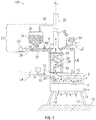
- FIGS. 1 , 2 , and 3 are schematic side elevation views, partially in cross-section, of three system and method embodiments 100, 200, and 300 in accordance with the present disclosure.
- Systems, apparatus, and methods of the present disclosure aim to solve or at least reduce the problem of energy loss as heat in combustion melters, and even in purely electric (Joule heated) melters.
- Embodiment 100 illustrated schematically in FIG. 1 includes a structure 2 (otherwise referred to herein as a melter) defining a melting chamber 4, a plurality of SC burners 6 producing a turbulent melt 8 of molten glass, molten rock, and the like, as indicated by curved arrows in turbulent melt 8 in melting chamber 4.
- a turbulent surface 10 is illustrated as viewable in cutout section 11.
- Batch feed conduit 15 may be positioned at an angle ⁇ 4 ranging from about 25 to about 75 degrees.
- a melter outlet 14, system supports 16, and plant floor 18 are illustrated schematically in FIG. 1 , as are exhaust conduit longitudinal axis L1.
- melter 2 and SC burners 6 produce an exhaust, indicated at arrow 20 in embodiment 100 of FIG. 1 .
- exhaust 20 would pass up exhaust conduit 22 and much energy as heat would be wasted.
- a feedstock heat exchange substructure 24 is provided as a section of exhaust conduit 22, substructure 24 including in embodiment 100 a refractory lining 26 and a metal superstructure 28, the latter possibly fluid-cooled or insulated as conditions dictate.
- One or more feedstock flow diverters 30 is provided internal of substructure 24 in embodiment 100 for effecting direct heat exchange from exhaust 20 flowing tortuously upward to feedstock 35 flowing tortuously downward.
- Feedstock flow diverters 30 may for example comprise one or more baffles, distributor plates, grids, and the like for causing a tortuous flow path for feedstock 35 and for exhaust 20.
- Feedstock flow diverters 30 may take any shape, for example flat plates, corrugated plates, plates having a variety of projections or protuberances therefrom such as spikes, knobs, lumps, bumps, and the like, of a variety of sizes, or all the same size.
- the relative flow of feedstock and exhaust through feedstock heat exchange substructure 24 may be counter-current, co-current, or cross-current. Flow of feedstock may be continuous, semi-continuous, semi-batch, or batch.
- feedstock could flow into feedstock heat exchange substructure 24 until feedstock heat exchange substructure 24 is partially full or completely full of feedstock, then the pre-heated stock may be dumped into melting chamber 4.
- feedstock heat exchange substructure 24 could flow into feedstock heat exchange substructure 24 until feedstock heat exchange substructure 24 is partially full or completely full of feedstock, then the pre-heated stock may be dumped into melting chamber 4.
- One way of accomplishing may be by use of a grating at the bottom of feedstock heat exchange substructure 24 having openings slightly smaller than the feedstock particle size.
- a feedstock supply structure 33 is provided in embodiment 100 comprising a horizontal feedstock supply conduit 32, one or more feedstock supply containers 34, and a feedstock advancing mechanism 36.
- Horizontal feedstock supply conduit 32 is at an angle to vertical ⁇ of about 90 degrees in embodiment 100.
- the section of the exhaust conduit 22 which connects the feedstock supply conduit 32 with the heat exchange substructure 24 and the heat exchange substructure 24 defines a heat exchange area A which is configured for a heat exchange from the exhaust 20 to the feedstock 35.
- Feedstock advancing mechanism 36 may be a piston, plunger, or other like component within horizontal feedstock supply conduit 32, and may be connected via a tie rod 38 or other feature to a prime mover 40, such as a reciprocating engine or motor.
- a feedstock flow control component 60 may comprise a sliding gate device, valve, or other component that functions to control and/or stop flow of feedstock in case of emergency.
- a vent conduit 42 may be provided, allowing any exhaust that should escape exhaust conduit 22 and travel into the feedstock supply structure to be vented back to exhaust conduit 22.
- One or more pressure relief devices may also be provided.
- feedstock supply structure 33 may be required in other embodiments where feedstock supply conduit 32 is not strictly horizontal, such as when angle to vertical ⁇ is less than 90 degrees, such as 85, 80, 75 degrees, or lower, depending on the feedstock composition, average particle size, size of equipment (internal diameters) and the like.
- a shaker device in addition to or in place of feedstock advancing mechanism, may be employed, with suitable flexible connections between components (or no physical connection) that shakes or agitates feedstock supply conduit 32.
- auxiliary batch feeders 64 may be provided, feeding batch or other material through an auxiliary batch feed conduit 65 and valve 62 into exhaust conduit 22 to be pre-heated in feedstock heat exchange substructure 24. Such arrangement may be beneficial if feedstock heat exchange substructure 24 is shut down for repair or renovation.
- Auxiliary batch feed conduit 65 may be positioned at an angle ⁇ 3 ranging from about 25 to about 75 degrees.
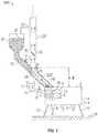
- FIG. 2 illustrates another system embodiment 200 in accordance with the present disclosure.
- System 200 includes a non-submerged combustion melter 44 having a plurality of non-SC burners 50 that combust a fuel with an oxidant above a non-turbulent molten pool of melt 46.
- a non-turbulent surface 48 of non-turbulent molten pool of melt 46 is very calm compared to the very turbulent SC embodiment illustrated schematically in FIG. 1 , embodiment 100.
- Embodiment 200 comprises a primary exhaust conduit 22A having a longitudinal axis L1, an offset exhaust conduit 22B having a longitudinal axis L2, an auxiliary exhaust conduit 22C, and an insulated exhaust conduit 22D.
- Feedstock supply structure 33A includes an angled feedstock supply conduit 32 including an insulated section 54, and insulation 55.
- Insulated section 54 is at an angle of ⁇ 1 ranging from about 25 to about 75 degrees to axis L1
- feedstock supply conduit 32 is at an angle of ⁇ 2 ranging from about 25 to about 75 degrees to axis L2, where ⁇ 1 and ⁇ 2 may be the same or different; in certain embodiments ⁇ 1 may be more than ⁇ 2 (for example, ⁇ 1 may be about 75 degrees, and ⁇ 2 may be about 45 degrees).
- Exhaust conduits 22A and 22D fluidly connect to insulated section 54 of feedstock supply conduit 32 through a first 3-way connector 56, while a second 3-way connector 58 fluidly connects insulated section 54, feedstock supply conduit 32, and offset exhaust conduit 22B.
- First and second 3-way connectors may be Y-connectors, T-connectors, and the like.
- Feedstock 35 flows by gravity out of feedstock supply container 34, controlled by size of angled feedstock supply conduit 32 and angle ⁇ 2 ranging from about 25 to about 75 degrees, or from about 25 to about 60 degrees, and optionally by valve, through insulated section 54 and into heat exchange substructure 24, and finally into melting chamber 4 of melter 44, as viewable in cutout section 11.
- a damper or other flow diverter mechanism 52 is provided to divert part or all of flow of exhaust 20 from melter 44 to flow through insulated conduit 54 rather than through primary exhaust conduit 22A.
- direct heat exchange may be provided only in heat exchange substructure 24, if flow diverter 52 is open, or direct heat exchange may be provided in both heat exchange substructure 24 and in insulated conduit 54, if flow diverter 52 is closed or partially closed.
- Flow diverter mechanism 52 is in turn connected to a prime mover (not illustrated) controlled for example by a supervisory melter controller.
- the heat exchange area A is defined by the heat exchange substructure 24, the insulated exhaust conduit 22D and the insulated section 54.
- conduit 54 the feedstock may be tumbling and closely packed, while in heat exchange substructure 24 the feedstock is falling and may be less compact, providing essentially two different heat exchange opportunities.
- non-SC combustion burners 50 may be replaced by SC burners; Joule heating elements may be employed in conjunction with SC or non-SC burners, or as complete replacements for all burners, although roof burners may be desired for start-up.
- FIG. 3 illustrates another system embodiment 300 in accordance with the present disclosure, wherein at least one of the one or more exhaust conduits comprises an angled, insulated exhaust conduit 22E serving as the heat exchange substructure.
- the angled, insulated exhaust conduit 22E fluidly connects melting chamber 4 to a 3-way flow connector 56, the 3-way flow connector 56 fluidly connecting angled, insulated exhaust conduit 22E with an angled feedstock supply conduit 32 and to a vertical exhaust conduit 22F.
- angled, insulated exhaust conduit 22E and feedstock supply conduit 32 are each positioned at an angle of ⁇ ranging from about 25 to about 75 degrees to axis L of vertical exhaust conduit 22F.
- Embodiment 300 may also include an exhaust flow control mechanism 52 (damper or other component) to vary the flow rate of exhaust through exhaust conduits 22E, 22F; for example, it may be desired to decrease the flow of exhaust 20 in order to provide more time for heat transfer from exhaust 20 to feedstock 35.
- embodiment 300 may include a feedstock flow control mechanism 70 to control or completely shut off flow of feedstock.
- the heat exchange area A is defined by the exhaust conduit 22E.
- FIGS. 4A and 4B are schematic side cross-sectional and axial cross-sectional views (A-A), respectively, of one indirect heat exchange substructure embodiment 24A in accordance with the present disclosure, including an internal plenum 80 (refractory, noble metal, or other high-temperature material) serving to route exhaust 20 from melter 2 through a space between plenum 80 and refractory 26.
- Plenum 80 also serves to define a passage for feedstock 35 to fall without directly contacting exhaust 20.
- a downcomer 82 optionally angled away from the melting chamber, for example at an angle ⁇ 5 to vertical ranging from about 25 to about 75 degrees, may be provided to enhance the tendency of exhaust 20 to travel up through the space between plenum 80 and refractory 26.
- plenum 80 is illustrated schematically in FIG. 4B as circular, but this could vary to other shapes such as rectangular, triangular, and the like, and a plurality of plenums 80 may be provided, for example two or more conduits having internal diameters larger than the feedstock size.
- the cross-sectional shape of refractory 26 and metal superstructure 28 may also vary from rectangular as illustrated in FIG. 4B .
- FIGS. 5A and 5B are schematic side cross-sectional and axial cross-sectional views (B-B), respectively, of another indirect heat exchange embodiment in accordance with the present disclosure.
- an internal feedstock supply conduit 90 is provided, which may be simply a continuation of feedstock supply conduit 32 illustrated in embodiments 100, 200, and 300.
- internal feedstock supply conduit may have a distal end 92 protruding in to melter 2 a short distance I order to enhance the tendency of melter exhaust 20 to traverse around internal feedstock supply conduit 90 as illustrated.
- distal end 92 may comprise one or more high-temperature refractory materials or one or more noble metals. While FIG. 5B illustrates internal feedstock conduit 90 and insulated exhaust conduit 22E as having circular cross-sections, other shapes such as rectangular, triangular, and the like may be employed.
- System 100 may be operated by a method comprising:
- Yet other methods may comprise:
- the initial raw material feedstock 35 may include any material suitable for forming molten inorganic materials having a weight average particle size such that most if not all of the feedstock is not fluidized when traversing through the heat exchange structure or exhaust conduit serving as the heat exchange structure.
- Such materials may include glass precursors or other non-metallic inorganic materials, such as, for example, limestone, glass cullet, feldspar, basalt or other rock wool forming material, and mixtures thereof.
- Typical examples of basalt that are compositionally stable and available in large quantities are reported in the aforementioned U.S.
- Patent Publication 2012/0104306 namely an ore having a larger amount of SiO2 (A, for high-temperature applications) and an ore having a smaller amount of SiO2 (B, for intermediate-temperature applications), both of which have approximately the same amount of Al2O3.
- Ore A can be spun into fiber, the resultant basalt fiber has heat-resistance problem at temperature ranges exceeding 750° C.
- Ore B is associated with higher energy cost for mass production of fiber.
- the basalt rock material feedstock for use on the systems and methods of the present disclosure may be selected from: (1) high-temperature ore (A) having substantially the same amount of Al2O3 and a larger amount of SiO2; (2) intermediate-temperature ore (B) having substantially the same amount of Al2O3 and a smaller amount of SiO2; and (3) a mixture of the high-temperature basalt rock ore (A) and the intermediate-temperature basalt rock ore (B).
- Basalt rock (basalt ore) is an igneous rock.
- major examples of the constituent mineral include: (1) plagioclase: Na(AlSi3O8)-Ca(Al2SiO8); (2) pyroxene: (Ca, Mg, Fe2+, Fe3+, Al, Ti)2[(Si, Al)2O6]; and (3) olivine: (Fe, Mg)2SiO4. Ukrainian products are inexpensive and good-quality.
- Tables 1 and 2 show examples of element ratios (wt. %) and the oxide-equivalent composition ratios (wt. %) determined by ICP analysis (using an inductively-coupled plasma spectrometer ICPV-8100 by Shimadzu Corporation) performed on a high-temperature basalt ore (for high-temperature applications), an intermediate-temperature basalt ore (for intermediate-temperature applications), and a glass consisting of 85% high-temperature ore and 15% intermediate-temperature ore.
- ICP analysis using an inductively-coupled plasma spectrometer ICPV-8100 by Shimadzu Corporation
- one glass composition for producing glass fibers is "E-glass," which typically includes 52-56% SiO2, 12-16% Al2O3, 0-0.8% Fe2O3, 16-25% CaO, 0-6% MgO, 0-10% B2O3, 0-2% Na2O+K2O, 0-1.5% TiO2 and 0-1% F2.
- Other glass batch compositions may be used, such as those described in assignee's published U.S. application 20080276652 .
- submerged combustion burners and burner panels may produce violent turbulence of the molten inorganic material in the SCM and may result in sloshing of molten material, pulsing of combustion burners, popping of large bubbles above submerged burners, ejection of molten material from the melt against the walls and ceiling of melter, and the like.
- one or more of these phenomena may result in undesirably short life of temperature sensors and other components used to monitor a submerged combustion melter's operation, making monitoring difficult, and use of signals from these sensors for melter control all but impossible for more than a limited time period.
- Processes and systems of the present disclosure may include indirect measurement of melt temperature in the melter itself, as disclosed in assignee's U.S.
- Patent 9,096,453 using one or more thermocouples for monitoring and/or control of the melter, for example using a controller.
- a signal may be transmitted by wire or wirelessly from a thermocouple to a controller, which may control the melter by adjusting any number of parameters, for example feed rate of feeder may be adjusted through a signal, and one or more of fuel and/or oxidant conduits 24, 22 may be adjusted via a signal, it being understood that suitable transmitters and actuators, such as valves and the like, are not illustrated for clarity.
- Melter apparatus in accordance with the present disclosure may also comprise one or more wall-mounted submerged combustion burners, and/or one or more roof-mounted burners (not illustrated). Roof-mounted burners may be useful to pre-heat the melter apparatus melting zone, and serve as ignition sources for one or more submerged combustion burners and/or burner panels. Melter apparatus having only wall-mounted, submerged-combustion burners or burner panels are also considered within the present disclosure. Roof-mounted burners may be oxy-fuel burners, but as they are only used in certain situations, are more likely to be air/fuel burners. Most often they would be shut-off after pre-heating the melter and/or after starting one or more submerged combustion burners.
- all submerged combustion burners and burner panels may be oxy/fuel burners or oxy-fuel burner panels (where "oxy" means oxygen, or oxygen-enriched air, as described earlier), but this is not necessarily so in all embodiments; some or all of the submerged combustion burners or burner panels may be air/fuel burners.
- heating may be supplemented by electrical heating in certain embodiments, in certain melter zones.
- Certain system embodiment may comprise burner panels as described in assignee's U.S. Patent Application Serial No. 14/838,148 filed August 27, 2014 comprising a burner panel body and one or more sets of concentric conduits for flow of oxidant and fuel.
- Certain burner panels disclosed therein include those wherein the outer conduit of at least some of the sets of concentric conduits are oxidant conduits, and the at least one inner conduit is one or more fuel conduits.
- Certain burner panel embodiments may comprise non-fluid cooled or fluid-cooled protective members comprising one or more noble metals.
- Certain burner panel embodiments may comprise non-fluid cooled or fluid-cooled protective members consisting essentially of one or more noble metals.
- Certain burner panel embodiments may comprise non-fluid cooled or fluid-cooled protective members consisting of one or more noble metals. Certain burner panel embodiments may comprise those wherein the lower fluid-cooled portion and the upper non-fluid cooled portion are positioned in layers, with the lower fluid-cooled portion supporting the sets of conduits and the associated protective members. Certain burner panel embodiments may comprise those wherein the non-fluid cooled protective member is a shaped annular disk having a through passage, the through passage of the shaped annular disk having an internal diameter substantially equal to but not larger than an internal diameter of the outer conduit.
- Certain burner panel embodiments may comprise those wherein an internal surface of the through passage of the shaped annular disk and a portion of a top surface of the shaped annular disk are not engulfed by the fluid-cooled or non-fluid-cooled portions of the panel body.
- Certain combustion burner panels may comprise a panel body having a first major surface defined by a lower fluid-cooled portion of the panel body, and a second major surface defined by an upper non-fluid cooled portion of the panel body, the panel body having at least one through passage extending from the first to the second major surface, the through passage diameter being greater in the lower fluid-cooled portion than in the upper non-fluid cooled portion, the panel body supporting at least one set of substantially concentric at least one inner conduit and an outer conduit, each conduit comprising proximal and distal ends, the at least one inner conduit forming a primary passage and the outer conduit forming a secondary passage between the outer conduit and the at least one inner conduit; and (b) a fluid-cooled protective member associated with each set and having connections for coolant fluid supply and return, each fluid-cooled protective member positioned adjacent at least a portion of the circumference of the outer conduit between the proximal and distal ends thereof at approximately a position of the fluid-cooled portion of the panel body.
- Certain burner panel embodiments may comprise those wherein each fluid-cooled protective member is a fluid-cooled collar having an internal diameter about the same as an external diameter of the outer conduit, the fluid-cooled collar having an external diameter larger than the internal diameter.
- Certain burner panel embodiments may comprise a mounting sleeve.
- the mounting sleeve having a diameter at least sufficient to accommodate the external diameter of the fluid-cooled collar.
- the burner panel may include only one or more fuel conduits, or only one or more oxidant conduits. These embodiments may be paired with other panels supplying fuel or oxidant (as the case might be), the pair resulting in combustion of the fuel from one panel with the oxidant from the other panel.
- the burner panel may comprise a pre-disposed layer or layers of glass, ceramic, refractory, and/or refractory metal or other protective material as a protective skull over the non-fluid cooled body portion or layer.
- the layer or layers of protective material may or may not be the same as the material to be melted in the SCM.
- Suitable materials for glass-contact refractory which may be present in SCMs and non-SC melters and downstream flow channels, and refractory panel bodies of burner panels, include AZS (alumina-zirconia-silica), ⁇ / ⁇ alumina, zirconium oxide, chromium oxide, chrome corundum, so-called "dense chrome", and the like.
- AZS alumina-zirconia-silica
- ⁇ / ⁇ alumina zirconium oxide
- chromium oxide chrome corundum
- so-called "dense chrome” material is available from Saint Gobain under the trade name SEFPRO, such as C1215 and C1221.
- Other useable "dense chrome” materials are available from the North American Refractories Co., Cleveland, Ohio (U.S.A.) under the trade designations SERV 50 and SERV 95.
- fused zirconia ZrO2
- fused cast AZS alumina-zirconia-silica
- rebonded AZS rebonded AZS
- fused cast alumina Al2O3
- the choice of a particular material may be dictated by the geometry of the apparatus, the type of material being produced, operating temperature, burner body panel geometry, and type of glass or other product being produced.
- fluid-cooled means use of a coolant fluid (heat transfer fluid) to transfer heat away from the component in question (such as structural walls of an SCM), either by the fluid traveling through the refractory of the panel, through conduits positioned in or adjacent the refractory of the panel, and the like, and does not include natural heat transfer that may occur by ambient air flowing past the panel, or ambient air merely existing adjacent a panel.
- heat transfer fluids may be any gaseous, liquid, slurry, or some combination of gaseous, liquid, and slurry compositions that functions or is capable of being modified to function as a heat transfer fluid.
- Gaseous heat transfer fluids may be selected from air, including ambient air and treated air (for example, air treated to remove moisture), inorganic gases, such as nitrogen, argon, and helium, organic gases such as fluoro-, chloro- and chlorofluorocarbons, including perfluorinated versions, such as tetrafluoromethane, and hexafluoroethane, and tetrafluoroethylene, and the like, and mixtures of inert gases with small portions of non-inert gases, such as hydrogen.
- Heat transfer liquids and slurries may be selected from liquids and slurries that may be organic, inorganic, or some combination thereof, for example, water, salt solutions, glycol solutions, oils and the like.
- Heat transfer fluids include steam (if cooler than the expected glass melt temperature), carbon dioxide, or mixtures thereof with nitrogen.
- Heat transfer fluids may be compositions comprising both gas and liquid phases, such as the higher chlorofluorocarbons.
- Certain SCMs and method embodiments of this disclosure may include fluid-cooled panels such as disclosed in assignee's U.S. Patent No. 8,769,992 .
- one or more fuel and/or oxidant conduits in the SCM and/or flow channel(s) downstream thereof may be adjustable with respect to direction of flow of the fuel or oxidant or both. Adjustment may be via automatic, semi-automatic, or manual control.
- Certain system embodiments may comprise a mount that mounts the fuel or oxidant conduit in a burner panel of the SCM and/or flow channel comprising a refractory, or refractory-lined ball joint.
- Other mounts may comprise rails mounted in slots in the wall or roof.
- the fuel and/or oxidant conduits may be mounted outside of the melter or channel, on supports that allow adjustment of the fuel or oxidant flow direction. Useable supports include those comprising ball joints, cradles, rails, and the like.
- Certain systems and processes of the present disclosure may utilize measurement and control schemes such as described in Applicant's U.S. Patent 9,096,453 , and/or feed batch densification systems and methods as described in assignee's co-pending U.S. Patent Application Serial No. 13/540,704, filed July 3, 2012 .
- Certain SCMs and processes of the present disclosure may utilize devices for delivery of treating compositions such as disclosed in assignee's U.S. Patent 8,973,405 .
- combustion (flame) temperature may be controlled by monitoring one or more parameters selected from velocity of the fuel, velocity of the primary oxidant, mass and/or volume flow rate of the fuel, mass and/or volume flow rate of the primary oxidant, energy content of the fuel, temperature of the fuel as it enters burners or burner panels, temperature of the primary oxidant as it enters burners or burner panels, temperature of the effluent (exhaust) at melter exhaust exit, pressure of the primary oxidant entering burners or burner panels, humidity of the oxidant, burner or burner panel geometry, combustion ratio, and combinations thereof.
- Certain SCMs and processes of this disclosure may also measure and/or monitor feed rate of batch or other feedstock materials, such as rock wool or mineral wool feedstock, glass batch, cullet, mat or wound roving and treatment compositions, mass of feed, and use these measurements for control purposes.
- Flow diverter positions may be adjusted or controlled to increase heat transfer in heat transfer substructures and exhaust conduits.
- conduits such as feedstock supply conduits, exhaust conduits, oxidant and fuel conduits of burners or burner panels of the present disclosure may be comprised of metal, ceramic, ceramic-lined metal, or combination thereof.
- Suitable metals include carbon steels, stainless steels, for example, but not limited to, 306 and 316 steel, as well as titanium alloys, aluminum alloys, and the like.
- High-strength materials like C-110 and C-125 metallurgies that are NACE qualified may be employed for burner body components.
- NACE corrosion prevention organization formerly known as the National Association of Corrosion Engineers, now operating under the name NACE International, Houston, Texas.
- Use of high strength steel and other high strength materials may significantly reduce the conduit wall thickness required, reducing weight of the conduits and/or space required for conduits. In certain locations, precious metals and/or noble metals (or alloys) may be used for portions or all of these conduits.
- a protective layer or layers or components may comprise an 80 wt. percent platinum/20 wt. percent rhodium alloy attached to a base metal using brazing, welding or soldering of certain regions, as further explained in assignee's International Patent Application Serial No. PCT/US13/42182, filed May 22, 2013 , now published WO2014189504 .
- alloys of two or more noble metals may have any range of noble metals.
- alloys of two noble metals may have a range of about 0.01 to about 99.99 percent of a first noble metal and 99.99 to 0.01 percent of a second noble metal.
- any and all ranges in between 0 and 99.99 percent first noble metal and 99.99 and 0 percent second noble metal are considered within the present disclosure, including 0 to about 99 percent of first noble metal; 0 to about 98 percent; 0 to about 97 percent; 0 to about 96; 0 to about 95; 0 to about 90; 0 to about 80; 0 to about 75; 0 to about 70; 0 to about 65; 0 to about 60; 0 to about 55; 0 to about 50; 0 to about 45, 0 to about 40; 0 to about 35; 0 to about 30; 0 to about 25; 0 to about 20; 0 to about 19; 0 to about 18; 0 to about 17; 0 to about 16; 0 to about 15; 0 to about 14; 0 to about 13; 0 to about 12; 0 to about 1 1 ; 0 to about 10; 0 to about 9; 0 to about 8; 0 to about 7; 0 to about 6; 0 to about 5; 0 to about
- the percentages of each individual noble metal may range from equal amounts of all noble metals in the composition (about 33.33 percent of each), to compositions comprising, or consisting essentially of, or consisting of 0.01 percent of a first noble metal, 0.01 percent of a second noble metal, and 99.98 percent of a third noble metal. Any and all ranges in between about 33.33 percent of each, and 0.01 percent of a first noble metal, 0.01 percent of a second noble metal, and 99.98 percent of a third noble metal, are considered within the present disclosure.
- the total quantities of fuel and oxidant used by burners or burner panels of the present disclosure may be such that the flow of oxygen may range from about 0.9 to about 1.2 of the theoretical stoichiometric flow of oxygen necessary to obtain the complete combustion of the fuel flow. Another expression of this statement is that the combustion ratio may range from about 0.9 to about 1.2.
- the amount of heat needed to be produced by combustion of fuel in the melter (and/or Joule heating) will depend upon the efficiency of the preheating of the feedstock in the feedstock heat exchange substructure. The larger the amount of heat transferred to the feedstock, the lower the heat energy required in the melter from the fuel and/or Joule elements.
- the velocity of the fuel in the various burners and/or burner panel embodiments depends on the burner/burner panel geometry used, but generally is at least about 15 meters/second (m/s).
- the upper limit of fuel velocity depends primarily on the desired penetration of flame and/or combustion products into the glass melt and the geometry of the burner panel; if the fuel velocity is too low, the flame temperature may be too low, providing inadequate temperature in the melter, which is not desired, and if the fuel flow is too high, flame and/or combustion products might impinge on a melter wall or roof, or cause carryover of melt into the exhaust, or be wasted, which is also not desired.
- Baffles may be provided extending from the roof, and/or in the melter exhaust conduit, such as in the heat exchange substructure, in order to safeguard against this.
- oxidant velocity should be monitored so that flame and/or combustion products do not impinge on an SCM wall or roof, or cause carryover of melt into the exhaust, or be wasted. Oxidant velocities depend on fuel flow rate and fuel velocity, but in general should not exceed about 200 ft/sec at 400 scfh flow rate.
- a combustion and/or Joule heating process control scheme may be employed.
- a master controller may be employed, but the disclosure is not so limited, as any combination of controllers could be used.
- the controller may be selected from PI controllers, PID controllers (including any known or reasonably foreseeable variations of these), and may compute a residual equal to a difference between a measured value and a set point to produce an output to one or more control elements.
- the controller may compute the residual continuously or non-continuously.
- Other possible implementations of the disclosure are those wherein the controller comprises more specialized control strategies, such as strategies selected from feed forward, cascade control, internal feedback loops, model predictive control, neural networks, and Kalman filtering techniques.
- control means to verify or regulate by comparing with a standard or desired value.
- Control may be closed loop, feedback, feed-forward, cascade, model predictive, adaptive, heuristic and combinations thereof.
- controller means a device at least capable of accepting input from sensors and meters in real time or near-real time, and sending commands directly to burner panel control elements, and/or to local devices associated with burner panel control elements able to accept commands.
- a controller may also be capable of accepting input from human operators; accessing databases, such as relational databases; sending data to and accessing data in databases, data warehouses or data marts; and sending information to and accepting input from a display device readable by a human.
- a controller may also interface with or have integrated therewith one or more software application modules, and may supervise interaction between databases and one or more software application modules.
- PID controller means a controller using proportional, integral, and derivative features. In some cases the derivative mode may not be used or its influence reduced significantly so that the controller may be deemed a PI controller. It will also be recognized by those of skill in the control art that there are existing variations of PI and PID controllers, depending on how the discretization is performed. These known and foreseeable variations of PI, PID and other controllers are considered within the disclosure.
- the controller may utilize Model Predictive Control (MPC).
- MPC is an advanced multivariable control method for use in multiple input/multiple output (MIMO) systems.
- MPC computes a sequence of manipulated variable adjustments in order to optimise the future behavior of the process in question. It may be difficult to explicitly state stability of an MPC control scheme, and in certain embodiments of the present disclosure it may be necessary to use nonlinear MPC.
- PID control may be used on strong mono-variable loops with few or nonproblematic interactions, while one or more networks of MPC might be used, or other multivariable control structures, for strong interconnected loops.
- computing time considerations may be a limiting factor.
- Some embodiments may employ nonlinear MPC.
- a feed forward algorithm if used, will in the most general sense be task specific, meaning that it will be specially designed to the task it is designed to solve. This specific design might be difficult to design, but a lot is gained by using a more general algorithm, such as a first or second order filter with a given gain and time constants.
Description
- This application claims priority of
U.S. Patent Application No. 14/844,198, filed on September 3, 2015 - The present disclosure relates generally to the field of combustion melters and apparatus, and method of use, and more specifically to submerged and conventional combustion melters, and method of their use, particularly for melting glass-forming materials, mineral wool forming materials, and other non-metallic inorganic materials.
- A submerged combustion melter (SCM) may be employed to melt glass batch and/or waste glass materials to produce molten glass, or may melt mineral wool feedstock to make mineral or rock wool, by passing oxygen, oxygen-enriched mixtures, or air along with a liquid, gaseous and/or particulate fuel (some of which may be in one or more of the feedstock materials), directly into a molten pool of glass or other material, usually through burners submerged in a turbulent melt pool. The introduction of high flow rates of products of combustion of the oxidant and fuel into the molten material, and the expansion of the gases during submerged combustion (SC), cause rapid melting of the feedstock and much turbulence and foaming. Conventional melters operate primarily by combusting fuel and oxidant above the molten pol of melt, and are very laminar in flow characteristics compared to SCMs. While most of the present disclosure discusses SCM, the disclosure is pertinent to conventional melters as well.
- Oxy-fuel burners and technologies provide high heat transfer rates, fuel consumption reductions (energy savings), reduced volume of flue gas, and reduction of pollutants emission, such as oxides of nitrogen (NOx), carbon monoxide (CO), and particulates. Despite the reduction of the flue gas volume that the substitution of combustion with air by combustion with pure oxygen or oxygen-enriched air yields, a significant amount of energy is lost in the flue gas (also referred to herein as exhaust or exhaust gases), especially for high temperature processes. For example, in an oxy-fuel fired glass furnace where all the fuel is combusted with pure oxygen, and for which the temperature of the flue gas at the furnace exhaust is of the order of 1350° C., typically 30% to 40% of the energy released by the combustion of the fuel is lost in the flue gas. It would be advantageous to recover some of the energy available from the flue gas in order to improve the economics of operating an oxy-fuel fired furnace, whether SCM or conventional melter.
- One technique consists in using the energy available in the flue gas to preheat and/or dry out the raw materials before loading them into the furnace. In the case of glass melting, the raw materials may comprise recycled glass, commonly referred to as cullet, and other minerals and chemicals in a pulverized form referred to as batch materials that have a relatively high water content. The energy exchange between the flue gas and the raw materials may be carried out in a batch/cullet preheater. Such devices are commonly available, for example from Zippe Inc. of Wertheim, Germany. Experience shows that this technology is difficult to operate when the batch represents more than 50% of the raw materials because of a tendency to plug. This limits the applicability of the technique to a limited number of glass melting operations that use a large fraction of cullet. Another drawback of this technique (according to the known art) is that the inlet temperature of the flue gas in the materials preheater must be generally kept lower than 600° C. In the case of an oxy-fuel fired furnace where the flue gas is produced at a temperature higher than 1000° C., one reference (
US 6,250,916 ) discloses that cooling of the flue gas prior to the materials preheater would be required. This would be counterproductive. - One low-cost non-metallic inorganic material being used to make inorganic fibers is basalt rock, sometimes referred to as lava rock.
US20120104306 discloses a method for manufacturing basalt filament, comprising the steps of grinding basalt rock as a material, washing a resultant ground rock, melting the ground rock that has been washed, transforming a molten product into fiber, and drawing the fiber in an aligned manner, and winding it. The temperature of the molten product in the melting step is 1400 to 1650° C., and log η is 2.15 to 2.35 dPa·s and more preferably 2.2 to 2.3 dPa·s, where η is the viscosity of the molten product. The size of basalt rock may be on the order of several mm to several dozens of mm, or several µm to several dozens of mm, according to this reference. - It would be an advanced in the melter art, and in particular the submerged combustion melter art, to improve energy usage while avoiding the heat loss from the exhaust while melting granular or pellets-size material (much larger than several dozens of mm), and prolong the run-length or campaign length of submerged combustion melters.
-
US1610376 discloses an angled exhaust conduit (6) and a 4-way flow connector (figure 1 ). The 4-way connector is fluidly connecting two angled exhaust conduits (23 , 24) and the vertical feedstock supply conduit (28). - In accordance with the present disclosure, submerged combustion (SC) burner panels are described that may reduce or eliminate problems with known SC burners, melters, and method of using the melters to produce molten glass and other non-metallic inorganic materials, such as rock wool and mineral wool.
- One aspect of this disclosure is a system according to
claim 1. - In an optional embodiment, the angle is ranging from 25 to 60 degrees.
- According to an embodiment of the invention, the heat exchange area is at least sectional configured for direct heat exchange from the exhaust to the feedstock.
- According to a further embodiment of the invention, the heat exchange area is at least sectional configured for indirect heat exchange from the exhaust to the feedstock.
- In these embodiments, an internal feedstock conduit may be provided in an exhaust conduit.
- The heat exchange substructure may comprise one or more internal structures for causing a tortuous flow path for the feedstock and for the exhaust.
- According to further embodiments of the invention, an auxiliary exhaust conduit is provided, the auxiliary exhaust conduit connecting at least two of the exhaust conduits.
- At least one control mechanism may be provided in at least one of the exhaust conduits, the control mechanism being configured for varying the flow rate of exhaust through the exhaust conduits.
- According to further embodiments of the invention, the feedstock supply structure comprises a feedstock advancing mechanism and/or a feedstock control component.
- The feedstock supply structure may comprise a vent conduit fluidly connected to an exhaust conduit, the vent conduit being configured for allowing to escape exhaust from the feedstock supply structure to the exhaust conduit.
- At least one auxiliary batch feeder may be provided, the auxiliary batch feeder being connected to the heat exchange area.
- The feedstock supply structure, the exhaust conduits and/or the heat exchange area (A) may be at least sectional isolated.
- According to another aspect of the invention, a method using an above mentioned system comprises:
- (a) Supplying a granular or pellet-sized feedstock from a feedstock supply structure to the heat exchange area,
- (b) supplying exhaust from the melting chamber to the heat exchange area,
- (c) preheating the granular or pellet-sized feedstock by direct and/or indirect contact with melter exhaust in the heat exchange area.
- The granules or pellets may range from 1cm to 10cm, especially from 1cm to 5cm, especially from 1cm to 2cm.
- According to another aspect of the invention, a feedstock supply structure apparatus for a system according to
claim 1 is provided. - In a preferred embodiment, the angle is ranging from 25 to 60 degrees.
- Furthermore, a system may comprise (or consisting essentially of, or consisting of):
- (a) A structure defining a melting chamber;
- (b) one or more exhaust conduits fluidly connected to the structure defining the melting chamber and comprising a heat exchange substructure, the one or more exhaust conduits positioned at an angle to vertical ranging from 0 to about 90 degrees (or from about 10 to about 75 degrees, or from about 25 to about 60 degrees); and
- (c) a feedstock supply structure fluidly connected to the one or more exhaust conduits.
- The angle is greater than 80 degrees, and the feedstock supply structure includes a feedstock advancing mechanism.
- The system may comprise:
- (a) A structure defining a melting chamber and a feedstock supply structure fluidly connected thereto;
- (b) one or more exhaust conduits and one or more feed conduits fluidly connected to the structure defining the melting chamber and the feedstock supply structure and comprising a heat exchange substructure, the one or more exhaust conduits positioned at an angle and the one or more feed conduits positioned at an angle to vertical ranging from 0 to about 90 degrees;
- (c) the feedstock supply structure fluidly connected to the one or more exhaust conduits.
- It advantageously if each of the angles ranges from about 10 to about 75 degrees, preferably from about 25 to about 60 degrees. In a special version of the preferred embodiment, each of the angles is greater than 80 degrees, and the feedstock supply structure includes a feedstock advancing mechanism.
- The feedstock supply structure and the heat exchange substructure are configured to allow feedstock having granule or pellet size feedstock to flow, preferably by gravity only, into the melting chamber and allow indirect heat exchange from at least some of the exhaust flowing from the melting chamber to at least some of the feedstock.
- The feedstock supply structure and the heat exchange substructure are configured to allow feedstock having granule or pellet size feedstock to flow, preferably by gravity only, into the melting chamber and allow direct heat exchange from at least some of the exhaust flowing from the melting chamber to at least some of the feedstock.
- The size of the feedstock granules or pellets ranges from about 1 cm to about 10 cm, preferably from about 1-5 cm and even more preferred from about 1-2 cm. It is preferred that the feedstock has a large enough minimum particle, granule or pellet size that it flows to the melter and withstands to be carried away by the exhaust, at least in the embodiments with direct heat transfer from the exhaust to the feedstock. Therefore, it is preferred that the gravity forces to the minimum sized particles, granules or pellets are higher than the flow resistance forces caused by the interaction of the particles, granules or pellets and the reverse course of the exhaust.
- In another aspect, optionally at least one of the one or more exhaust conduits is at an angle of 0 degrees to vertical, and the feedstock supply structure comprises;
a horizontal feedstock supply conduit fluidly connected to the at least one of the one or more exhaust conduits, preferably to a vertical exhaust conduit, above the heat exchange substructure,
a feedstock supply container fluidly connected to the horizontal feedstock supply conduit, and
a feedstock advancing mechanism disposed in the horizontal feedstock supply conduit, the feedstock advancing mechanism in turn connected to a prime mover. - In another aspect, the heat exchange substructure comprises one or more internal structures (baffles, distributor plates and grids) for causing a tortuous flow path for the feedstock and/or for the exhaust, wherein the internal structures are preferably out of the group baffles, distributor plates and grids.
- In another aspect, at least one of the one or more exhaust conduits comprises the first vertical exhaust conduit comprising the heat exchange substructure fluidly connecting the melting chamber to a first 3-way flow connector, the first 3-way flow connector fluidly connecting the first vertical exhaust conduit comprising the heat exchange substructure with a second vertical exhaust conduit and an angled exhaust conduit, that can optionally serve as an angled insulated feed conduit, the angled exhaust conduit being at an angle ranging from about 25 to about 60 degrees to vertical, the angled exhaust conduit fluidly connected to a second 3-way flow connector, the second 3-way flow connector fluidly connecting the angled exhaust conduit to a third vertical exhaust conduit and with an angled feedstock supply conduit, and the feedstock supply structure comprises:
- a feedstock supply container fluidly connected to the angled feedstock supply conduit, and
- the first 3-way flow connector or the second vertical exhaust conduit comprising a damper mechanism disposed therein for diverting at least a portion of the exhaust to the first angled exhaust conduit, the damper mechanism in turn connected to a prime mover.
- In another aspect of the invention, the system comprises an auxiliary exhaust connection between the second and third vertical exhaust conduits.
- In another aspect of the invention, at least one of the one or more exhaust conduits comprises an angled exhaust conduit serving as the heat exchange substructure, the angled exhaust conduit fluidly connecting the melter chamber to a 3-way flow connector, the 3-way flow connector fluidly connecting the angled exhaust conduit with an angled feedstock supply conduit and to a vertical exhaust conduit, the feedstock supply structure comprises a feedstock supply container fluidly connected to the angled feedstock supply conduit.
- In another aspect, the system comprises a vent conduit fluidly connecting the feedstock supply container to the second vertical exhaust conduit.
- Another aspect is a feedstock supply structure apparatus preferably for a system as it is described above and below comprising (or consisting essentially of, or consisting of):
- (a) An exhaust conduit fluidly and mechanically connectable to a structure defining a melting chamber, the exhaust conduit positioned at an angle to vertical ranging from 0 to about 90 degrees;
- (b) the exhaust conduit comprising a heat exchange substructure; and
- (c) a feedstock supply structure fluidly connected to the exhaust conduit.
- In another aspect the feedstock supply structure apparatus (preferably for a system as described above and below) comprises:
- (a) one or more exhaust conduits and one or more feed conduits fluidly and mechanically connectable to a structure defining a melting chamber, the one or more exhaust conduit positioned at an angle to vertical ranging from 0 to about 90 degrees and the one or more feed conduits positioned at an angle to vertical ranging from 0 to about 90 degrees;
- (b) the one or more exhaust conduits and one or more feed conduits comprising an angled, insulated feed conduit; and
- (c) a feedstock supply structure fluidly connected to the heat exchange substructure.
- In another aspect of the feedstock supply structure, the exhaust conduit is at an angle of 0 degrees to vertical, and the feedstock supply structure comprises;
a horizontal feedstock supply conduit fluidly connected to the exhaust conduit above the heat exchange substructure,
a feedstock supply container fluidly connected to the horizontal feedstock supply conduit, and
a feedstock advancing mechanism disposed in the horizontal feedstock supply conduit, the feedstock advancing mechanism in turn connected to a prime mover. - In another aspect of the feedstock supply structure, the exhaust conduit comprises a first vertical exhaust conduit comprising the heat exchange substructure fluidly connected to a first 3-way flow connector, the first 3-way flow connector fluidly connecting the first vertical exhaust conduit comprising the heat exchange substructure with a second vertical exhaust conduit and an angled exhaust conduit, the angled exhaust conduit being at an angle ranging from about 25 to about 60 degrees to vertical, the angled exhaust conduit fluidly connected to a second 3-way flow connector, the second 3-way flow connector fluidly connecting the angled exhaust conduit to a third vertical exhaust conduit and with an angled feedstock supply conduit, the feedstock supply structure further comprising:
- A feedstock supply container fluidly connected to the angled feedstock supply conduit, and
- the first 3-way flow connector or the second vertical exhaust conduit comprising a damper mechanism disposed therein for diverting at least a portion of the exhaust to the first angled exhaust conduit, the damper mechanism in turn connected to a prime mover.
- According to another aspect, at least one of the one or more the exhaust conduits comprises a first vertical exhaust conduit and a second exhaust conduit fluidly connectable to the heat exchange substructure and the melting chamber by a first 3-way flow connector, the first 3-way flow connector fluidly connecting the first vertical exhaust conduit comprising the heat exchange substructure with a second vertical exhaust conduit via an angled, insulated feed conduit, the angled, insulated feed conduit being at an angle ranging from about 25 to about 60 degrees to vertical, the angled, insulated feed conduit fluidly connected to a second 3-way flow connector, the second 3-way flow connector fluidly connecting the angled, insulated feed conduit to the second vertical exhaust conduit and with an angled feedstock supply conduit, the feedstock supply structure further comprising:
- A feedstock supply container fluidly connected to the angled feedstock supply conduit, and
- the first 3-way flow connector or the second vertical exhaust conduit comprising a damper mechanism disposed therein for diverting at least a portion of the exhaust to the angled, insulated exhaust conduit.
- In another aspect of the feedstock supply structure, the exhaust conduit (in special embodiments at least one of the one or more exhaust conduits) comprises an angled exhaust conduit serving as the heat exchange substructure, the angled exhaust conduit fluidly connecting the melter chamber to a 3-way flow connector, the 3-way flow connector fluidly connecting the angled exhaust conduit with an angled feedstock supply conduit and to a vertical exhaust conduit, the feedstock supply structure comprises a feedstock supply container fluidly connected to the angled feedstock supply conduit.
- Another aspect of this disclosure is a method comprising (or consisting essentially of, or consisting of):
- (a) Supplying a granular or pellet-sized feedstock to an exhaust conduit from a melter, the exhaust conduit comprising a heat exchange substructure or the exhaust conduit serving as a heat exchange substructure;
- (b) preheating the granular or pellet-sized feedstock by indirect or direct contact with melter exhaust in the heat exchange substructure.
- In another aspect of the method the supplying is by gravity feed only, wherein the size of the feedstock granules or pellets ranges from about 1 cm to about 10 cm, preferably from about 1-5 cm and even more preferred from about 1-2 cm.
- Other system, apparatus, and method embodiments, such as methods of producing molten non-metallic inorganic materials such as molten glass or molten rock, in conventional melters and SCMs, are considered aspects of this disclosure. Certain methods within the disclosure include methods wherein the fuel may be a substantially gaseous fuel selected from the group consisting of methane, natural gas, liquefied natural gas, propane, carbon monoxide, hydrogen, steam-reformed natural gas, atomized oil or mixtures thereof, and the oxidant may be an oxygen stream comprising at least 90 mole percent oxygen.
- Systems, apparatus, and methods of the disclosure will become more apparent upon review of the brief description of the drawings, the detailed description of the disclosure, and the claims that follow.
- The manner in which the objectives of the disclosure and other desirable characteristics can be obtained is explained in the following description and attached drawings in which:
-
FIGS. 1 ,2 , and3 are schematic side elevation views, partially in cross-section, of three system and method embodiments in accordance with the present disclosure; -
FIGS. 4A and 4B are schematic side cross-sectional and axial cross-sectional views, respectively, of one indirect heat exchange embodiment in accordance with the present disclosure; and -
FIGS. 5A and 5B are schematic side cross-sectional and axial cross-sectional views, respectively, of another indirect heat exchange embodiment in accordance with the present disclosure. - It is to be noted, however, that the appended drawings are schematic in nature, may not be to scale, and illustrate only typical embodiments of this disclosure and are therefore not to be considered limiting of its scope, for the disclosure may admit to other equally effective embodiments.
- In the following description, numerous details are set forth to provide an understanding of the disclosed systems, apparatus, and methods. However, it will be understood by those skilled in the art that the systems, apparatus, and methods covered by the claims may be practiced without these details and that numerous variations or modifications from the specifically described embodiments may be possible and are deemed within the claims. For example, wherever the term "comprising" is used, embodiments and/or components where "consisting essentially of" and "consisting of" are explicitly disclosed herein and are part of this disclosure. All published patent applications and patents referenced herein are hereby explicitly incorporated herein by reference. In the event definitions of terms in the referenced patents and applications conflict with how those terms are defined in the present application, the definitions for those terms that are provided in the present application shall be deemed controlling. All percentages herein are based on weight unless otherwise specified.
- As explained briefly in the Background, one drawback to present melters, especially those employing oxy-fuel burners and technologies, despite the fact that they provide high heat transfer rates, fuel consumption reductions (energy savings), reduced volume of flue gas, and reduction of pollutants emission, such as oxides of nitrogen (NOx), carbon monoxide (CO), and particulates, a significant amount of energy is lost in the flue gas (also referred to herein as exhaust or exhaust gases), especially for high temperature processes. For example, in an oxy-fuel fired glass furnace where all the fuel is combusted with pure oxygen, and for which the temperature of the flue gas at the furnace exhaust is of the order of 1350° C., typically 30% to 40% of the energy released by the combustion of the fuel is lost in the flue gas. The present application is devoted to resolving this challenge by pre-heating large size feedstock prior to that feedstock entering the melter. As used herein, unless indicated to the contrary, "feedstock" means pieces of porous, semi-porous, or solid rock or other non-metallic inorganic material having a weight average particle size ranging from about 1 cm to about 10 cm, or from about 2 to about 5 cm, or from about 1 to about 2 cm. The only upper limit on feedstock weight average particle size is the internal diameter of feedstock supply structure components, as described herein, while the lower size limit is determined by angle of flow, flow rate of feedstock, and (in those embodiments where heat exchange is direct) flow rate of exhaust.
- Various terms are used throughout this disclosure. "Submerged" as used herein means that combustion gases emanate from combustion burners or combustion burner panels under the level of the molten glass; the burners or burner panels may be floor-mounted, wall-mounted, or in melter embodiments comprising more than one submerged combustion burner, any combination thereof (for example, two floor mounted burner panels and one wall mounted burner panel). Burner panels (such as described in assignee's
U.S. Patent Application Serial No. 14/838,148, filed August 27, 2015 - As used herein the phrase "combustion gases" as used herein means substantially gaseous mixtures comprised primarily of combustion products, such as oxides of carbon (such as carbon monoxide, carbon dioxide), oxides of nitrogen, oxides of sulfur, and water, as well as partially combusted fuel, non-combusted fuel, and any excess oxidant. Combustion products may include liquids and solids, for example soot and unburned liquid fuels. "Exhaust", "melter exhaust", and "melter flue gas" are equivalent terms and refer to a combination of combustion gases and effluent from the feedstock being melted, such as adsorbed water, water of hydration, CO2 liberated from CaCO3, and the like. Therefore exhaust may comprise oxygen or other oxidants, nitrogen, combustion products (including but not limited to, carbon dioxide, carbon monoxide, NOx, SOx, H2S, and water), uncombusted fuel, reaction products of melt-forming ingredients (for example, but not limited to, basalt, sand (primarily SiO2), clay, limestone (primarily CaCO3), burnt dolomitic lime, borax and boric acid, and the like.
- "Oxidant" as used herein includes air, gases having the same molar concentration of oxygen as air (for example "synthetic air"), oxygen-enriched air (air having oxygen concentration greater than 21 mole percent), and "pure" oxygen grades, such as industrial grade oxygen, food grade oxygen, and cryogenic oxygen. Oxygen-enriched air may have 50 mole percent or more oxygen, and in certain embodiments may be 90 mole percent or more oxygen.
- The term "fuel", according to this disclosure, means a combustible composition comprising a major portion of, for example, methane, natural gas, liquefied natural gas, propane, hydrogen, steam-reformed natural gas, atomized hydrocarbon oil, combustible powders and other flowable solids (for example coal powders, carbon black, soot, and the like), and the like. Fuels useful in the disclosure may comprise minor amounts of non-fuels therein, including oxidants, for purposes such as premixing the fuel with the oxidant, or atomizing liquid or particulate fuels. As used herein the term "fuel" includes gaseous fuels, liquid fuels, flowable solids, such as powdered carbon or particulate material, waste materials, slurries, and mixtures or other combinations thereof.
- The sources of oxidant and fuel may be one or more conduits, pipelines, storage facilities, cylinders, or, in embodiments where the oxidant is air, ambient air. Oxygen-enriched oxidants may be supplied from a pipeline, cylinder, storage facility, cryogenic air separation unit, membrane permeation separator, or adsorption unit such as a vacuum swing adsorption unit.
-
FIGS. 1 ,2 , and3 are schematic side elevation views, partially in cross-section, of three system andmethod embodiments Embodiment 100 illustrated schematically inFIG. 1 includes a structure 2 (otherwise referred to herein as a melter) defining amelting chamber 4, a plurality ofSC burners 6 producing aturbulent melt 8 of molten glass, molten rock, and the like, as indicated by curved arrows inturbulent melt 8 inmelting chamber 4. Aturbulent surface 10 is illustrated as viewable incutout section 11. Abatch feeder 12 for feeding particulates and/or powdered batch materials (materials having weight average particle size less than about 1 cm, or less than about 1 mm) through abatch feed conduit 15 andvalve arrangement 13, such as one or more glass batch materials, is illustrated fluidly attached tomelter 2.Batch feed conduit 15 may be positioned at an angle θ4 ranging from about 25 to about 75 degrees. Amelter outlet 14, system supports 16, andplant floor 18 are illustrated schematically inFIG. 1 , as are exhaust conduit longitudinal axis L1. - During operation of
embodiment 100,melter 2 andSC burners 6 produce an exhaust, indicated atarrow 20 inembodiment 100 ofFIG. 1 . In previously known systems and methods,exhaust 20 would pass upexhaust conduit 22 and much energy as heat would be wasted. In accordance withembodiment 100 of the present disclosure, a feedstockheat exchange substructure 24 is provided as a section ofexhaust conduit 22,substructure 24 including in embodiment 100 arefractory lining 26 and ametal superstructure 28, the latter possibly fluid-cooled or insulated as conditions dictate. One or morefeedstock flow diverters 30 is provided internal ofsubstructure 24 inembodiment 100 for effecting direct heat exchange fromexhaust 20 flowing tortuously upward tofeedstock 35 flowing tortuously downward.Feedstock flow diverters 30 may for example comprise one or more baffles, distributor plates, grids, and the like for causing a tortuous flow path forfeedstock 35 and forexhaust 20.Feedstock flow diverters 30 may take any shape, for example flat plates, corrugated plates, plates having a variety of projections or protuberances therefrom such as spikes, knobs, lumps, bumps, and the like, of a variety of sizes, or all the same size. In certain embodiments the relative flow of feedstock and exhaust through feedstockheat exchange substructure 24 may be counter-current, co-current, or cross-current. Flow of feedstock may be continuous, semi-continuous, semi-batch, or batch. For example, in certain embodiments feedstock could flow into feedstockheat exchange substructure 24 until feedstockheat exchange substructure 24 is partially full or completely full of feedstock, then the pre-heated stock may be dumped intomelting chamber 4. One way of accomplishing that may be by use of a grating at the bottom of feedstockheat exchange substructure 24 having openings slightly smaller than the feedstock particle size. - Referring again to
FIG. 1 andembodiment 100, afeedstock supply structure 33 is provided inembodiment 100 comprising a horizontalfeedstock supply conduit 32, one or morefeedstock supply containers 34, and afeedstock advancing mechanism 36. Horizontalfeedstock supply conduit 32 is at an angle to vertical θ of about 90 degrees inembodiment 100. - The section of the
exhaust conduit 22 which connects thefeedstock supply conduit 32 with theheat exchange substructure 24 and theheat exchange substructure 24 defines a heat exchange area A which is configured for a heat exchange from theexhaust 20 to thefeedstock 35. -
Feedstock advancing mechanism 36 may be a piston, plunger, or other like component within horizontalfeedstock supply conduit 32, and may be connected via atie rod 38 or other feature to aprime mover 40, such as a reciprocating engine or motor. A feedstockflow control component 60 may comprise a sliding gate device, valve, or other component that functions to control and/or stop flow of feedstock in case of emergency. Avent conduit 42 may be provided, allowing any exhaust that should escapeexhaust conduit 22 and travel into the feedstock supply structure to be vented back toexhaust conduit 22. One or more pressure relief devices (not illustrated) may also be provided. It should be recognized that such an arrangement of feedstock supply structure 33 (including a feedstock advancing mechanism) may be required in other embodiments wherefeedstock supply conduit 32 is not strictly horizontal, such as when angle to vertical θ is less than 90 degrees, such as 85, 80, 75 degrees, or lower, depending on the feedstock composition, average particle size, size of equipment (internal diameters) and the like. In yet other embodiments, in addition to or in place of feedstock advancing mechanism, a shaker device (not illustrated) may be employed, with suitable flexible connections between components (or no physical connection) that shakes or agitatesfeedstock supply conduit 32. - Optionally, one or more
auxiliary batch feeders 64 may be provided, feeding batch or other material through an auxiliarybatch feed conduit 65 andvalve 62 intoexhaust conduit 22 to be pre-heated in feedstockheat exchange substructure 24. Such arrangement may be beneficial if feedstockheat exchange substructure 24 is shut down for repair or renovation. Auxiliarybatch feed conduit 65 may be positioned at an angle θ3 ranging from about 25 to about 75 degrees. -
FIG. 2 illustrates anothersystem embodiment 200 in accordance with the present disclosure.System 200 includes anon-submerged combustion melter 44 having a plurality ofnon-SC burners 50 that combust a fuel with an oxidant above a non-turbulent molten pool ofmelt 46. Anon-turbulent surface 48 of non-turbulent molten pool ofmelt 46 is very calm compared to the very turbulent SC embodiment illustrated schematically inFIG. 1 ,embodiment 100.Embodiment 200 comprises aprimary exhaust conduit 22A having a longitudinal axis L1, an offsetexhaust conduit 22B having a longitudinal axis L2, anauxiliary exhaust conduit 22C, and aninsulated exhaust conduit 22D.Feedstock supply structure 33A includes an angledfeedstock supply conduit 32 including an insulatedsection 54, andinsulation 55.Insulated section 54 is at an angle of θ1 ranging from about 25 to about 75 degrees to axis L1, andfeedstock supply conduit 32 is at an angle of θ2 ranging from about 25 to about 75 degrees to axis L2, where θ1 and θ2 may be the same or different; in certain embodiments θ1 may be more than θ2 (for example, θ1 may be about 75 degrees, and θ2 may be about 45 degrees). -
Exhaust conduits insulated section 54 offeedstock supply conduit 32 through a first 3-way connector 56, while a second 3-way connector 58 fluidly connects insulatedsection 54,feedstock supply conduit 32, and offsetexhaust conduit 22B. First and second 3-way connectors may be Y-connectors, T-connectors, and the like.Feedstock 35 flows by gravity out offeedstock supply container 34, controlled by size of angledfeedstock supply conduit 32 and angle θ2 ranging from about 25 to about 75 degrees, or from about 25 to about 60 degrees, and optionally by valve, throughinsulated section 54 and intoheat exchange substructure 24, and finally intomelting chamber 4 ofmelter 44, as viewable incutout section 11. A damper or otherflow diverter mechanism 52 is provided to divert part or all of flow ofexhaust 20 frommelter 44 to flow through insulatedconduit 54 rather than throughprimary exhaust conduit 22A. Inembodiment 200, direct heat exchange may be provided only inheat exchange substructure 24, ifflow diverter 52 is open, or direct heat exchange may be provided in bothheat exchange substructure 24 and ininsulated conduit 54, ifflow diverter 52 is closed or partially closed.Flow diverter mechanism 52 is in turn connected to a prime mover (not illustrated) controlled for example by a supervisory melter controller. - In this embodiment, the heat exchange area A is defined by the
heat exchange substructure 24, the insulatedexhaust conduit 22D and theinsulated section 54. - During operation of
embodiment 200, inconduit 54 the feedstock may be tumbling and closely packed, while inheat exchange substructure 24 the feedstock is falling and may be less compact, providing essentially two different heat exchange opportunities. - It will be understood that one or more
non-SC combustion burners 50 may be replaced by SC burners; Joule heating elements may be employed in conjunction with SC or non-SC burners, or as complete replacements for all burners, although roof burners may be desired for start-up. -
FIG. 3 illustrates anothersystem embodiment 300 in accordance with the present disclosure, wherein at least one of the one or more exhaust conduits comprises an angled,insulated exhaust conduit 22E serving as the heat exchange substructure. The angled,insulated exhaust conduit 22E fluidly connects meltingchamber 4 to a 3-way flow connector 56, the 3-way flow connector 56 fluidly connecting angled,insulated exhaust conduit 22E with an angledfeedstock supply conduit 32 and to avertical exhaust conduit 22F. Inembodiment 300, angled,insulated exhaust conduit 22E andfeedstock supply conduit 32 are each positioned at an angle of θ ranging from about 25 to about 75 degrees to axis L ofvertical exhaust conduit 22F.Embodiment 300 may also include an exhaust flow control mechanism 52 (damper or other component) to vary the flow rate of exhaust throughexhaust conduits exhaust 20 in order to provide more time for heat transfer fromexhaust 20 tofeedstock 35. Similarly,embodiment 300 may include a feedstockflow control mechanism 70 to control or completely shut off flow of feedstock. - In this embodiment, the heat exchange area A is defined by the
exhaust conduit 22E. -
FIGS. 4A and 4B are schematic side cross-sectional and axial cross-sectional views (A-A), respectively, of one indirect heatexchange substructure embodiment 24A in accordance with the present disclosure, including an internal plenum 80 (refractory, noble metal, or other high-temperature material) serving to routeexhaust 20 frommelter 2 through a space betweenplenum 80 and refractory 26.Plenum 80 also serves to define a passage forfeedstock 35 to fall without directly contactingexhaust 20. Adowncomer 82, optionally angled away from the melting chamber, for example at an angle θ5 to vertical ranging from about 25 to about 75 degrees, may be provided to enhance the tendency ofexhaust 20 to travel up through the space betweenplenum 80 and refractory 26. The cross-sectional shape ofplenum 80 is illustrated schematically inFIG. 4B as circular, but this could vary to other shapes such as rectangular, triangular, and the like, and a plurality ofplenums 80 may be provided, for example two or more conduits having internal diameters larger than the feedstock size. The cross-sectional shape of refractory 26 andmetal superstructure 28 may also vary from rectangular as illustrated inFIG. 4B . -
FIGS. 5A and 5B are schematic side cross-sectional and axial cross-sectional views (B-B), respectively, of another indirect heat exchange embodiment in accordance with the present disclosure. In this embodiment an internalfeedstock supply conduit 90 is provided, which may be simply a continuation offeedstock supply conduit 32 illustrated inembodiments FIG. 5A , internal feedstock supply conduit may have adistal end 92 protruding in to melter 2 a short distance I order to enhance the tendency ofmelter exhaust 20 to traverse around internalfeedstock supply conduit 90 as illustrated. Due to the high temperatures experienced at thedistal end 92, distal end 92 (or a part or all of internal feedstock conduit 90) may comprise one or more high-temperature refractory materials or one or more noble metals. WhileFIG. 5B illustratesinternal feedstock conduit 90 andinsulated exhaust conduit 22E as having circular cross-sections, other shapes such as rectangular, triangular, and the like may be employed. - Methods of the disclosure may be summarized for
system embodiment System 100 may be operated by a method comprising: - (a) Supplying a granular or pellet-sized feedstock to an exhaust conduit from a melter, the exhaust conduit comprising a heat exchange substructure;
- (b) preheating the granular or pellet-sized feedstock by indirect contact with melter exhaust in the heat exchange substructure.
- Other methods may comprise:
- (a) Supplying a granular or pellet-sized feedstock to an exhaust conduit from a melter, the exhaust conduit comprising a heat exchange substructure;
- (b) preheating the granular or pellet-sized feedstock by direct contact with melter exhaust in the heat exchange substructure.
- Yet other methods may comprise:
- (a) Supplying a granular or pellet-sized feedstock to an exhaust conduit from a melter, the exhaust conduit serving as a heat exchange substructure;
- (b) preheating the granular or pellet-sized feedstock by direct contact with melter exhaust in the exhaust conduit.
- The initial
raw material feedstock 35 may include any material suitable for forming molten inorganic materials having a weight average particle size such that most if not all of the feedstock is not fluidized when traversing through the heat exchange structure or exhaust conduit serving as the heat exchange structure. Such materials may include glass precursors or other non-metallic inorganic materials, such as, for example, limestone, glass cullet, feldspar, basalt or other rock wool forming material, and mixtures thereof. Typical examples of basalt that are compositionally stable and available in large quantities are reported in the aforementionedU.S. Patent Publication 2012/0104306 , namely an ore having a larger amount of SiO2 (A, for high-temperature applications) and an ore having a smaller amount of SiO2 (B, for intermediate-temperature applications), both of which have approximately the same amount of Al2O3. Although ore A can be spun into fiber, the resultant basalt fiber has heat-resistance problem at temperature ranges exceeding 750° C. Ore B, on the other hand, is associated with higher energy cost for mass production of fiber. The basalt rock material feedstock for use on the systems and methods of the present disclosure may be selected from: (1) high-temperature ore (A) having substantially the same amount of Al2O3 and a larger amount of SiO2; (2) intermediate-temperature ore (B) having substantially the same amount of Al2O3 and a smaller amount of SiO2; and (3) a mixture of the high-temperature basalt rock ore (A) and the intermediate-temperature basalt rock ore (B). - Basalt rock (basalt ore) is an igneous rock. According to
U.S. Patent Publication 2012/0104306 , major examples of the constituent mineral include: (1) plagioclase: Na(AlSi3O8)-Ca(Al2SiO8); (2) pyroxene: (Ca, Mg, Fe2+, Fe3+, Al, Ti)2[(Si, Al)2O6]; and (3) olivine: (Fe, Mg)2SiO4. Ukrainian products are inexpensive and good-quality. - Tables 1 and 2 (from
U.S. Patent Publication 2012/0104306 ) show examples of element ratios (wt. %) and the oxide-equivalent composition ratios (wt. %) determined by ICP analysis (using an inductively-coupled plasma spectrometer ICPV-8100 by Shimadzu Corporation) performed on a high-temperature basalt ore (for high-temperature applications), an intermediate-temperature basalt ore (for intermediate-temperature applications), and a glass consisting of 85% high-temperature ore and 15% intermediate-temperature ore.TABLE 1 Ore (for high-temp.) (wt %) Ore (for intermediate-temp.) (wt %) Ore (for high-temp.) 85 wt % Ore (for intermediate-temp.) 15 wt % (wt %) Si 23.5∼28.8 23.5∼28.5 25.0∼28.8 Al 8.7∼9.3 8.7∼9.3 9.0∼9.5 Fe 6.0∼6.6 6.0∼7.1 5.7∼6.7 Ca 4.0∼4.5 5.6∼6.1 4.2∼4.7 Na 2.1∼2.3 1.8∼2.0 2.0∼2.3 K 1.4∼1.8 1.2∼1.5 1.4∼1.9 Mg 0.1∼1.6 1.4∼3.0 1.5∼1.7 Ti 0.4∼0.6 0.5∼0.7 0.4∼0.6 Mn 0.1∼0.2 0.1∼0.2 0.1∼0.2 P 0.05∼0.10 0.05∼0.09 0.07∼0.10 B 0.02∼0.08 0.01∼0.06 0.03∼0.10 Ba 0.03∼0.05 0.03∼0.05 0.09 Sr 0.02∼0.04 0.02∼0.04 0.02∼0.05 Zr 0.01∼0.04 0.01∼0.04 0.01∼0.03 Cr 0.01∼0.03 0.01∼0.03 0.01∼0.03 S 0.01∼0.03 0.01∼0.03 0.01∼0.03 TABLE 2 Ore (for high-temp.) (wt %) Ore (for intermediate-temp.) (wt %) Ore (for high-temp.) 85 wt % Ore (for intermediate-temp.) 15 wt % (wt %) SiO2 57.1∼61.2 54.0∼58.2 57.7∼60.6 Al2O3 16.1∼19.2 14.9∼18.1 16.5∼18.9 FeO + Fe2O3 8.0∼9.7 8.1∼9.6 7.7∼9.6 CaO 5.5∼6.8 7.5∼8.8 5.8∼7.0 Na2O 2.8∼3.3 2.2∼2.9 2.6∼3.2 K2O 1.8∼2.1 1.4∼1.8 1.8∼2.2 MgO 0.20∼2.5 1.4∼4.8 0.2∼2.8 TiO2 0.7∼1.0 0.8∼1.1 0.1∼0.3 MnO 0.1∼0.3 0.1∼0.3 0.1∼0.3 P2O5 0.1∼0.3 0.1∼0.3 0.1∼0.3 B2O3 0.1∼0.3 0.04∼0.20 0.04∼0.30 BaO 0.03∼0.07 0.02∼0.06 0.03∼0.12 SrO 0.02∼0.06 0.02∼0.07 0.01∼0.06 ZrO2 0.02∼0.05 0.02∼0.05 0.01∼0.30 Cr2O3 0.01∼0.05 0.01∼0.05 0.01∼0.04 SO 0.01∼0.03 0.01∼0.03 0.01∼0.03 - In embodiments wherein glass batch is used as a supplemental feedstock, one glass composition for producing glass fibers is "E-glass," which typically includes 52-56% SiO2, 12-16% Al2O3, 0-0.8% Fe2O3, 16-25% CaO, 0-6% MgO, 0-10% B2O3, 0-2% Na2O+K2O, 0-1.5% TiO2 and 0-1% F2. Other glass batch compositions may be used, such as those described in assignee's published
U.S. application 20080276652 . - As noted herein, submerged combustion burners and burner panels may produce violent turbulence of the molten inorganic material in the SCM and may result in sloshing of molten material, pulsing of combustion burners, popping of large bubbles above submerged burners, ejection of molten material from the melt against the walls and ceiling of melter, and the like. Frequently, one or more of these phenomena may result in undesirably short life of temperature sensors and other components used to monitor a submerged combustion melter's operation, making monitoring difficult, and use of signals from these sensors for melter control all but impossible for more than a limited time period. Processes and systems of the present disclosure may include indirect measurement of melt temperature in the melter itself, as disclosed in assignee's
U.S. Patent 9,096,453 oxidant conduits - Melter apparatus in accordance with the present disclosure may also comprise one or more wall-mounted submerged combustion burners, and/or one or more roof-mounted burners (not illustrated). Roof-mounted burners may be useful to pre-heat the melter apparatus melting zone, and serve as ignition sources for one or more submerged combustion burners and/or burner panels. Melter apparatus having only wall-mounted, submerged-combustion burners or burner panels are also considered within the present disclosure. Roof-mounted burners may be oxy-fuel burners, but as they are only used in certain situations, are more likely to be air/fuel burners. Most often they would be shut-off after pre-heating the melter and/or after starting one or more submerged combustion burners. In certain embodiments, if there is a possibility of carryover of batch particles to the exhaust, one or more roof-mounted burners could be used to form a curtain to prevent particulate carryover. In certain embodiments, all submerged combustion burners and burner panels may be oxy/fuel burners or oxy-fuel burner panels (where "oxy" means oxygen, or oxygen-enriched air, as described earlier), but this is not necessarily so in all embodiments; some or all of the submerged combustion burners or burner panels may be air/fuel burners. Furthermore, heating may be supplemented by electrical heating in certain embodiments, in certain melter zones.
- Certain system embodiment may comprise burner panels as described in assignee's
U.S. Patent Application Serial No. 14/838,148 filed August 27, 2014 - Suitable materials for glass-contact refractory, which may be present in SCMs and non-SC melters and downstream flow channels, and refractory panel bodies of burner panels, include AZS (alumina-zirconia-silica), α/β alumina, zirconium oxide, chromium oxide, chrome corundum, so-called "dense chrome", and the like. One "dense chrome" material is available from Saint Gobain under the trade name SEFPRO, such as C1215 and C1221. Other useable "dense chrome" materials are available from the North American Refractories Co., Cleveland, Ohio (U.S.A.) under the trade designations SERV 50 and SERV 95. Other suitable materials for components that require resistance to high temperatures are fused zirconia (ZrO2), fused cast AZS (alumina-zirconia-silica), rebonded AZS, or fused cast alumina (Al2O3). The choice of a particular material may be dictated by the geometry of the apparatus, the type of material being produced, operating temperature, burner body panel geometry, and type of glass or other product being produced.
- The term "fluid-cooled" means use of a coolant fluid (heat transfer fluid) to transfer heat away from the component in question (such as structural walls of an SCM), either by the fluid traveling through the refractory of the panel, through conduits positioned in or adjacent the refractory of the panel, and the like, and does not include natural heat transfer that may occur by ambient air flowing past the panel, or ambient air merely existing adjacent a panel. For example, portions of the heat transfer substructure nearest the melter, distal portion of feedstock supply conduits, and the like may require fluid cooling. Heat transfer fluids may be any gaseous, liquid, slurry, or some combination of gaseous, liquid, and slurry compositions that functions or is capable of being modified to function as a heat transfer fluid. Gaseous heat transfer fluids may be selected from air, including ambient air and treated air (for example, air treated to remove moisture), inorganic gases, such as nitrogen, argon, and helium, organic gases such as fluoro-, chloro- and chlorofluorocarbons, including perfluorinated versions, such as tetrafluoromethane, and hexafluoroethane, and tetrafluoroethylene, and the like, and mixtures of inert gases with small portions of non-inert gases, such as hydrogen. Heat transfer liquids and slurries may be selected from liquids and slurries that may be organic, inorganic, or some combination thereof, for example, water, salt solutions, glycol solutions, oils and the like. Other possible heat transfer fluids include steam (if cooler than the expected glass melt temperature), carbon dioxide, or mixtures thereof with nitrogen. Heat transfer fluids may be compositions comprising both gas and liquid phases, such as the higher chlorofluorocarbons. Certain SCMs and method embodiments of this disclosure may include fluid-cooled panels such as disclosed in assignee's
U.S. Patent No. 8,769,992 . - In certain SCMs, one or more fuel and/or oxidant conduits in the SCM and/or flow channel(s) downstream thereof may be adjustable with respect to direction of flow of the fuel or oxidant or both. Adjustment may be via automatic, semi-automatic, or manual control. Certain system embodiments may comprise a mount that mounts the fuel or oxidant conduit in a burner panel of the SCM and/or flow channel comprising a refractory, or refractory-lined ball joint. Other mounts may comprise rails mounted in slots in the wall or roof. In yet other embodiments the fuel and/or oxidant conduits may be mounted outside of the melter or channel, on supports that allow adjustment of the fuel or oxidant flow direction. Useable supports include those comprising ball joints, cradles, rails, and the like.
- Certain systems and processes of the present disclosure may utilize measurement and control schemes such as described in Applicant's
U.S. Patent 9,096,453 U.S. Patent Application Serial No. 13/540,704, filed July 3, 2012 U.S. Patent 8,973,405 . - Certain systems, apparatus, and method embodiments of this disclosure may be controlled by one or more controllers. For example, combustion (flame) temperature may be controlled by monitoring one or more parameters selected from velocity of the fuel, velocity of the primary oxidant, mass and/or volume flow rate of the fuel, mass and/or volume flow rate of the primary oxidant, energy content of the fuel, temperature of the fuel as it enters burners or burner panels, temperature of the primary oxidant as it enters burners or burner panels, temperature of the effluent (exhaust) at melter exhaust exit, pressure of the primary oxidant entering burners or burner panels, humidity of the oxidant, burner or burner panel geometry, combustion ratio, and combinations thereof. Certain SCMs and processes of this disclosure may also measure and/or monitor feed rate of batch or other feedstock materials, such as rock wool or mineral wool feedstock, glass batch, cullet, mat or wound roving and treatment compositions, mass of feed, and use these measurements for control purposes. Flow diverter positions may be adjusted or controlled to increase heat transfer in heat transfer substructures and exhaust conduits.
- Various conduits, such as feedstock supply conduits, exhaust conduits, oxidant and fuel conduits of burners or burner panels of the present disclosure may be comprised of metal, ceramic, ceramic-lined metal, or combination thereof. Suitable metals include carbon steels, stainless steels, for example, but not limited to, 306 and 316 steel, as well as titanium alloys, aluminum alloys, and the like. High-strength materials like C-110 and C-125 metallurgies that are NACE qualified may be employed for burner body components. (As used herein, "NACE" refers to the corrosion prevention organization formerly known as the National Association of Corrosion Engineers, now operating under the name NACE International, Houston, Texas.) Use of high strength steel and other high strength materials may significantly reduce the conduit wall thickness required, reducing weight of the conduits and/or space required for conduits. In certain locations, precious metals and/or noble metals (or alloys) may be used for portions or all of these conduits. Noble metals and/or other exotic corrosion and/or fatigue-resistant materials such as platinum (Pt), ruthenium (Ru), rhodium (Rh), palladium (Pd), silver (Ag), osmium (Os), iridium (Ir), and gold (Au); alloys of two or more noble metals; and alloys of one or more noble metals with a base metal may be employed. In certain embodiments a protective layer or layers or components may comprise an 80 wt. percent platinum/20 wt. percent rhodium alloy attached to a base metal using brazing, welding or soldering of certain regions, as further explained in assignee's International Patent Application Serial No.
PCT/US13/42182, filed May 22, 2013 , now publishedWO2014189504 . - When in alloyed form, alloys of two or more noble metals may have any range of noble metals. For example, alloys of two noble metals may have a range of about 0.01 to about 99.99 percent of a first noble metal and 99.99 to 0.01 percent of a second noble metal. Any and all ranges in between 0 and 99.99 percent first noble metal and 99.99 and 0 percent second noble metal are considered within the present disclosure, including 0 to about 99 percent of first noble metal; 0 to about 98 percent; 0 to about 97 percent; 0 to about 96; 0 to about 95; 0 to about 90; 0 to about 80; 0 to about 75; 0 to about 70; 0 to about 65; 0 to about 60; 0 to about 55; 0 to about 50; 0 to about 45, 0 to about 40; 0 to about 35; 0 to about 30; 0 to about 25; 0 to about 20; 0 to about 19; 0 to about 18; 0 to about 17; 0 to about 16; 0 to about 15; 0 to about 14; 0 to about 13; 0 to about 12; 0 to about 1 1 ; 0 to about 10; 0 to about 9; 0 to about 8; 0 to about 7; 0 to about 6; 0 to about 5; 0 to about 4; 0 to about 3; 0 to about 2; 0 to about 1 ; and 0 to about 0.5 percent of a first noble metal; with the balance comprising a second noble metal, or consisting essentially of (or consisting of) a second noble metal (for example with one or more base metals present at no more than about 10 percent, or no more than about 9 percent base metal, or no more than about 8, or about 7, or about 6, or about 5, or about 4, or about 3, or about 2, or no more than about 1 percent base metal).
- In certain noble metal alloy embodiments comprising three or more noble metals, the percentages of each individual noble metal may range from equal amounts of all noble metals in the composition (about 33.33 percent of each), to compositions comprising, or consisting essentially of, or consisting of 0.01 percent of a first noble metal, 0.01 percent of a second noble metal, and 99.98 percent of a third noble metal. Any and all ranges in between about 33.33 percent of each, and 0.01 percent of a first noble metal, 0.01 percent of a second noble metal, and 99.98 percent of a third noble metal, are considered within the present disclosure.
- The choice of a particular material is dictated among other parameters by the chemistry, pressure, and temperature of fuel and oxidant used and type of melt to be produced with certain feedstocks. The skilled artisan, having knowledge of the particular application, pressures, temperatures, and available materials, will be able design the most cost effective, safe, and operable heat transfer substructures, feedstock and exhaust conduits, burners, burner panels, and melters for each particular application without undue experimentation.
- The total quantities of fuel and oxidant used by burners or burner panels of the present disclosure may be such that the flow of oxygen may range from about 0.9 to about 1.2 of the theoretical stoichiometric flow of oxygen necessary to obtain the complete combustion of the fuel flow. Another expression of this statement is that the combustion ratio may range from about 0.9 to about 1.2. The amount of heat needed to be produced by combustion of fuel in the melter (and/or Joule heating) will depend upon the efficiency of the preheating of the feedstock in the feedstock heat exchange substructure. The larger the amount of heat transferred to the feedstock, the lower the heat energy required in the melter from the fuel and/or Joule elements.
- In SCMs, the velocity of the fuel in the various burners and/or burner panel embodiments depends on the burner/burner panel geometry used, but generally is at least about 15 meters/second (m/s). The upper limit of fuel velocity depends primarily on the desired penetration of flame and/or combustion products into the glass melt and the geometry of the burner panel; if the fuel velocity is too low, the flame temperature may be too low, providing inadequate temperature in the melter, which is not desired, and if the fuel flow is too high, flame and/or combustion products might impinge on a melter wall or roof, or cause carryover of melt into the exhaust, or be wasted, which is also not desired. Baffles may be provided extending from the roof, and/or in the melter exhaust conduit, such as in the heat exchange substructure, in order to safeguard against this. Similarly, oxidant velocity should be monitored so that flame and/or combustion products do not impinge on an SCM wall or roof, or cause carryover of melt into the exhaust, or be wasted. Oxidant velocities depend on fuel flow rate and fuel velocity, but in general should not exceed about 200 ft/sec at 400 scfh flow rate.
- A combustion and/or Joule heating process control scheme may be employed. A master controller may be employed, but the disclosure is not so limited, as any combination of controllers could be used. The controller may be selected from PI controllers, PID controllers (including any known or reasonably foreseeable variations of these), and may compute a residual equal to a difference between a measured value and a set point to produce an output to one or more control elements. The controller may compute the residual continuously or non-continuously. Other possible implementations of the disclosure are those wherein the controller comprises more specialized control strategies, such as strategies selected from feed forward, cascade control, internal feedback loops, model predictive control, neural networks, and Kalman filtering techniques.
- The term "control", used as a transitive verb, means to verify or regulate by comparing with a standard or desired value. Control may be closed loop, feedback, feed-forward, cascade, model predictive, adaptive, heuristic and combinations thereof. The term "controller" means a device at least capable of accepting input from sensors and meters in real time or near-real time, and sending commands directly to burner panel control elements, and/or to local devices associated with burner panel control elements able to accept commands. A controller may also be capable of accepting input from human operators; accessing databases, such as relational databases; sending data to and accessing data in databases, data warehouses or data marts; and sending information to and accepting input from a display device readable by a human. A controller may also interface with or have integrated therewith one or more software application modules, and may supervise interaction between databases and one or more software application modules.
- The phrase "PID controller" means a controller using proportional, integral, and derivative features. In some cases the derivative mode may not be used or its influence reduced significantly so that the controller may be deemed a PI controller. It will also be recognized by those of skill in the control art that there are existing variations of PI and PID controllers, depending on how the discretization is performed. These known and foreseeable variations of PI, PID and other controllers are considered within the disclosure.
- The controller may utilize Model Predictive Control (MPC). MPC is an advanced multivariable control method for use in multiple input/multiple output (MIMO) systems. MPC computes a sequence of manipulated variable adjustments in order to optimise the future behavior of the process in question. It may be difficult to explicitly state stability of an MPC control scheme, and in certain embodiments of the present disclosure it may be necessary to use nonlinear MPC. In so-called advanced control of various systems, PID control may be used on strong mono-variable loops with few or nonproblematic interactions, while one or more networks of MPC might be used, or other multivariable control structures, for strong interconnected loops. Furthermore, computing time considerations may be a limiting factor. Some embodiments may employ nonlinear MPC.
- A feed forward algorithm, if used, will in the most general sense be task specific, meaning that it will be specially designed to the task it is designed to solve. This specific design might be difficult to design, but a lot is gained by using a more general algorithm, such as a first or second order filter with a given gain and time constants.
Claims (14)
- System (100, 200, 300) comprising:(a) a structure (2) defining a melting chamber (4),(b) at least one feedstock supply structure (33, 33A) fluidly connected to the structure (2) defining the melting chamber (4),(c) one or more exhaust conduit (22, 22A, 22B, 22C, 22D, 22E, 22F) fluidly connected to the structure (2) defining the melting chamber (4),(d) a heat exchange area (A),(e) the feedstock (35) flowing through the heat exchange area (A) to the melting chamber (4),(f) at least some of the exhaust (20) flowing from the melting chamber (4) flowing through the heat exchange area (A),(g) the heat exchange area (A) being configured for allowing heat exchange from the at least some of the exhaust (20) to at least some of the feedstock (35),(h) wherein the heat exchange area (A) comprises at least one section which is positioned at an angle (θ, θ1, θ2, θ3) to the vertical ranging from 0 to 90 degrees,(i) wherein at least one exhaust conduit (22, 22A, 22B, 22F) is connected to the heat exchange area (A), and(j) wherein the heat exchange area (A) comprises a heat exchange substructure (24),(k) wherein at least one of the one or more exhaust conduits (22, 22A, 22B, 22F) comprises an angled exhaust conduit (22E) serving as the heat exchange substructure (24),characterized in that(I) the angled exhaust conduit (22E) fluidly connecting the melter chamber (4) to a 3-way flow connector (56),(m)the 3-way flow connector (56) fluidly connecting the angled exhaust conduit (22E) with an angled feedstock supply conduit (32) and to a vertical exhaust conduit (22F),(n) the feedstock supply structure (33, 33A) comprises a feedstock supply container (34) fluidly connected to the angled feedstock supply conduit (32),(o) the angle (θ, θ1, θ2, θ3) is ranging from 10 to 75 degrees.
- The system according to claim 1, wherein the angle (θ, θ1, θ2, θ3) is ranging from 25 to 60 degrees.
- The system according to claim 1 or claim 2, wherein the heat exchange area (A) being at least sectional configured for direct heat exchange from the exhaust (20) to the feedstock (35).
- The system according to any of the preceding claims, wherein the heat exchange area (A) being at least sectional configured for indirect heat exchange from the exhaust (20) to the feedstock (35).
- The system according to claim 4, wherein an internal feedstock conduit (90) is provided in an exhaust conduit (22E).
- The system according to any of the preceding claims, wherein the heat exchange substructure (24) comprises one or more internal structures (30) for causing a tortuous flow path for the feedstock (35) and for the exhaust (20).
- The system according to any of the preceding claims, wherein an auxiliary exhaust conduit (22C) is provided, the auxiliary exhaust conduit (22C) connecting at least two of the exhaust conduits (22, 22A, 22B, 22F).
- The system according to any of the preceding claims, wherein at least one control mechanism (52) is provided in at least one of the exhaust conduits (22, 22A, 22B, 22D, 22E, 22F), the control mechanism (52) being configured for varying the flow rate of exhaust through the exhaust conduits (22, 22A, 22B, 22D, 22E, 22F).
- The system according to any of the preceding claims, wherein the feedstock supply structure (33, 33A) comprises a feedstock advancing mechanism (36) and/or a feedstock control component (60).
- The system according to any of the preceding claims, wherein the feedstock supply structure (33, 33A) comprises a vent conduit (42) fluidly connected to an exhaust conduit (22, 22B, 22F), the feedstock supply structure (33, 33A) being configured for allowing to escape exhaust from the feedstock supply structure (33, 33A) to the exhaust conduit (22, 22B, 22F).
- A method using a system (100, 200, 300) according to any one of the preceding claims, the method comprising:(a) supplying a granular or pellet-sized feedstock (35) from the feedstock supply structure (33, 33A) to the heat exchange area (A),(b) supplying exhaust from the melting chamber to the heat exchange area (A),(c) preheating the granular or pellet-sized feedstock (35) by direct and/or indirect contact with melter exhaust (20) in the heat exchange area (A).
- The method according to claim 11, wherein the granules or pellets ranges from 1cm to 10cm, especially from 1cm to 5cm, especially from 1cm to 2 cm.
- A feedstock supply structure (33, 33A) apparatus for a system (100, 200, 300) according to any one of the claims 1 to 10 comprising:(a) At least one feedstock supply conduit (32), fluidly and mechanically connectable to a structure (2) defining a melting chamber (4),(b) one or more exhaust conduit (22, 22A, 22B, 22C, 22D, 22E, 22F) fluidly connected to the structure defining the melting chamber (4),(c) a heat exchange area (A),(d) the feedstock flowing through the heat exchange area (A) to the melting chamber,(e) at least some of the exhaust flowing from the melting chamber flowing through the heat exchange area (A),(f) the heat exchange area (A) being configured for allowing heat exchange from the at least some of the exhaust to at least some of the feedstock (35),(g) wherein the heat exchange area (A) comprises at least one section which is positioned at an angle (θ, θ1, θ2, θ3) to the vertical ranging from 0 to 90 degrees(h) wherein at least one exhaust conduit (22, 22A, 22B, 22F) is connected to the heat exchange area (A), and(i) wherein the heat exchange area (A) comprises a heat exchange substructure (24), characterized in that(j) at least one of the one or more exhaust conduits (22, 22A, 22B, 22F) comprises an angled exhaust conduit (22E) serving as the heat exchange substructure (24),(k) the angled exhaust conduit (22E) fluidly connecting the melter chamber (4) to a 3-way flow connector (56),(l) the 3-way flow connector (56) fluidly connecting the angled exhaust conduit (22E) with an angled feedstock supply conduit (32) and to a vertical exhaust conduit (22F),(m)the angle (θ, θ1, θ2, θ3) is ranging from 10 to 75 degrees,(n) the feedstock supply structure (33, 33A) comprises a feedstock supply container (34) fluidly connected to the angled feedstock supply conduit (32).
- The feedstock supply structure (33, 33A) apparatus according to claim 13, wherein the angle (θ, θ1, θ2, θ3) is ranging from 25 to 60 degrees.
Priority Applications (3)
| Application Number | Priority Date | Filing Date | Title |
|---|---|---|---|
| EP19166477.0A EP3543216A1 (en) | 2015-09-03 | 2016-09-02 | Apparatus for pre-heating feedstock to a melter using melter exhaust |
| SI201630279T SI3138820T1 (en) | 2015-09-03 | 2016-09-02 | Apparatus and method for pre-heating feedstock to a melter using melter exhaust |
| PL16187117T PL3138820T3 (en) | 2015-09-03 | 2016-09-02 | Apparatus and method for pre-heating feedstock to a melter using melter exhaust |
Applications Claiming Priority (1)
| Application Number | Priority Date | Filing Date | Title |
|---|---|---|---|
| US14/844,198 US9815726B2 (en) | 2015-09-03 | 2015-09-03 | Apparatus, systems, and methods for pre-heating feedstock to a melter using melter exhaust |
Related Child Applications (2)
| Application Number | Title | Priority Date | Filing Date |
|---|---|---|---|
| EP19166477.0A Division-Into EP3543216A1 (en) | 2015-09-03 | 2016-09-02 | Apparatus for pre-heating feedstock to a melter using melter exhaust |
| EP19166477.0A Division EP3543216A1 (en) | 2015-09-03 | 2016-09-02 | Apparatus for pre-heating feedstock to a melter using melter exhaust |
Publications (2)
| Publication Number | Publication Date |
|---|---|
| EP3138820A1 EP3138820A1 (en) | 2017-03-08 |
| EP3138820B1 true EP3138820B1 (en) | 2019-05-08 |
Family
ID=56853546
Family Applications (2)
| Application Number | Title | Priority Date | Filing Date |
|---|---|---|---|
| EP16187117.3A Revoked EP3138820B1 (en) | 2015-09-03 | 2016-09-02 | Apparatus and method for pre-heating feedstock to a melter using melter exhaust |
| EP19166477.0A Pending EP3543216A1 (en) | 2015-09-03 | 2016-09-02 | Apparatus for pre-heating feedstock to a melter using melter exhaust |
Family Applications After (1)
| Application Number | Title | Priority Date | Filing Date |
|---|---|---|---|
| EP19166477.0A Pending EP3543216A1 (en) | 2015-09-03 | 2016-09-02 | Apparatus for pre-heating feedstock to a melter using melter exhaust |
Country Status (6)
| Country | Link |
|---|---|
| US (2) | US9815726B2 (en) |
| EP (2) | EP3138820B1 (en) |
| CA (1) | CA2940188A1 (en) |
| PL (1) | PL3138820T3 (en) |
| SI (1) | SI3138820T1 (en) |
| TR (1) | TR201908026T4 (en) |
Cited By (1)
| Publication number | Priority date | Publication date | Assignee | Title |
|---|---|---|---|---|
| WO2024036067A1 (en) * | 2022-08-09 | 2024-02-15 | Owens-Brockway Glass Container Inc. | Hydrogen-fueled submerged combustion melter and glass melting system including the same |
Families Citing this family (13)
| Publication number | Priority date | Publication date | Assignee | Title |
|---|---|---|---|---|
| WO2017040163A1 (en) * | 2015-08-31 | 2017-03-09 | Ocv Intellectual Capital, Llc | Batch inlet spool |
| US10246362B2 (en) | 2016-06-22 | 2019-04-02 | Johns Manville | Effective discharge of exhaust from submerged combustion melters and methods |
| US10301208B2 (en) * | 2016-08-25 | 2019-05-28 | Johns Manville | Continuous flow submerged combustion melter cooling wall panels, submerged combustion melters, and methods of using same |
| JP7333159B2 (en) * | 2016-12-26 | 2023-08-24 | 日本電気硝子株式会社 | Method for producing alkali-free glass substrate |
| US11759834B2 (en) * | 2017-11-08 | 2023-09-19 | Plasma Tech Holdings, Llc | Efficient fiber manufacturing |
| US10836668B2 (en) * | 2018-01-24 | 2020-11-17 | Owens-Brockway Glass Container Inc. | Furnace system |
| US11667555B2 (en) * | 2020-02-12 | 2023-06-06 | Owens-Brockway Glass Container Inc. | Glass redox control in submerged combustion melting |
| US11912608B2 (en) | 2019-10-01 | 2024-02-27 | Owens-Brockway Glass Container Inc. | Glass manufacturing |
| US20220411306A1 (en) * | 2020-09-30 | 2022-12-29 | Owens-Brockway Glass Container Inc. | Feeder Alcove and Batch Feeding Apparats for a Melter |
| IT202000007099A1 (en) * | 2020-04-03 | 2021-10-03 | Comb Consulting Italy S R L | FURNACE FOR THE MELTING OF VETRIFIABLE MATERIAL |
| US20220098078A1 (en) * | 2020-09-30 | 2022-03-31 | Owens-Brockway Glass Container Inc. | Submerged combustion melting exhaust systems |
| IT202100015662A1 (en) * | 2021-06-15 | 2022-12-15 | Qd S R L | EXCHANGE EQUIPMENT FOR EXCHANGING HEAT AND/OR MASS BETWEEN A GRANULAR MATERIAL AND A GAS STREAM |
| US20230278904A1 (en) * | 2022-03-01 | 2023-09-07 | Jeffrey C. Alexander | Batch And Cullet Proportioning Apparatus |
Citations (11)
| Publication number | Priority date | Publication date | Assignee | Title |
|---|---|---|---|---|
| US2057393A (en) | 1928-07-27 | 1936-10-13 | Johns Manville | Process and furnace for making mineral wool |
| US2593197A (en) | 1949-09-29 | 1952-04-15 | Owens Illinois Glass Co | Inclined melter furnace and method of melting glass |
| FR1557797A (en) | 1967-12-15 | 1969-02-21 | ||
| FR2281902A1 (en) | 1974-08-14 | 1976-03-12 | Saint Gobain | ADVANCED GLASS MANUFACTURING |
| EP0135446A1 (en) | 1983-09-14 | 1985-03-27 | Saint Gobain Vitrage International | Method and apparatus for melting glass and uses of this apparatus |
| DE3716687C1 (en) | 1987-05-19 | 1988-11-24 | Zippe Gmbh & Co | Plate heat exchanger for preheating broken glass or similar bulk materials |
| EP0426082A1 (en) | 1989-10-30 | 1991-05-08 | Praxair Technology, Inc. | Glassmelting method with reduced NOx generation |
| US5125943A (en) | 1990-08-06 | 1992-06-30 | Gas Research Institute | Combined batch and cullet preheater with separation and remixing |
| WO1997025285A1 (en) | 1996-01-05 | 1997-07-17 | Isover Saint-Gobain | Formed body, and method and device for producing it |
| WO1999037591A1 (en) | 1998-01-26 | 1999-07-29 | Saint-Gobain Vitrage | Method and device for melting and refining materials capable of being vitrified |
| WO2011154106A1 (en) | 2010-06-08 | 2011-12-15 | Beteiligungen Sorg Gmbh & Co. Kg | Method and apparatus for feeding preheaters for glass melting installations |
Family Cites Families (400)
| Publication number | Priority date | Publication date | Assignee | Title |
|---|---|---|---|---|
| US1875474A (en) | 1932-09-06 | To libbey-owens | ||
| GB191301772A (en) | 1913-01-22 | 1914-01-22 | Louis Frederick Tooth | Improvements in or relating to Gas-fired Furnaces or Kilns. |
| GB191407633A (en) | 1914-03-26 | 1915-03-26 | Louis Frederick Tooth | Improved Gas-fired Furnace for the Cupellation or Refining of Silver, Glass Bending, Enamelling and other like purposes. |
| GB164073A (en) | 1920-01-29 | 1921-05-30 | Morris William Travers | Improvements in furnaces |
| US1636151A (en) | 1922-08-23 | 1927-07-19 | Shaw John Schofield | Furnace for melting and refining glass and other like purposes |
| US1579353A (en) | 1924-11-01 | 1926-04-06 | Good Robert | Water-cooled bridge |
| US1716433A (en) | 1925-03-17 | 1929-06-11 | Ellis Foster Co | Submerged combustion process |
| US1706857A (en) | 1925-08-14 | 1929-03-26 | Hartford Empire Co | Apparatus for the precise determination of the level of glass in alpha furnace |
| US1610376A (en) | 1925-08-20 | 1926-12-14 | Pittsburgh Plate Glass Co | Process and apparatus for making glass |
| US1883023A (en) | 1926-05-11 | 1932-10-18 | Edwin E Slick | Glass furnace |
| US1679295A (en) | 1927-01-13 | 1928-07-31 | Hazel Atlas Glass Co | Bridge wall for glass tanks |
| US1989103A (en) | 1932-02-06 | 1935-01-29 | Laclede Christy Clay Products | Glass melting tank |
| US1944855A (en) | 1932-07-28 | 1934-01-23 | Hartford Empire Co | Method of and apparatus for making glass |
| US1937321A (en) | 1933-01-16 | 1933-11-28 | Hartford Empire Co | Apparatus for making glass |
| US2042560A (en) | 1934-09-28 | 1936-06-02 | Andrew H Stewart | Furnace wall |
| US2064546A (en) | 1935-04-06 | 1936-12-15 | Pittsburgh Plate Glass Co | Glass melting tank |
| US2174533A (en) | 1937-02-23 | 1939-10-03 | Theodore S See | Submerged combustion control system |
| US2269459A (en) | 1937-08-11 | 1942-01-13 | Owens Corning Fiberglass Corp | Tubular fiber |
| US2118479A (en) | 1938-03-24 | 1938-05-24 | Submerged Comb Company Of Amer | Submerged combustion burner |
| US2432942A (en) | 1943-04-05 | 1947-12-16 | Submerged Comb Company Of Amer | Submerged combustion system |
| US2455907A (en) | 1944-04-15 | 1948-12-07 | Owens Corning Fiberglass Corp | Apparatus for melting glass |
| US2718096A (en) | 1947-07-17 | 1955-09-20 | Union Des Verreries Mecaniques | Apparatus for melting glass and the like |
| US2691689A (en) | 1948-01-12 | 1954-10-12 | Saint Gobain | Glass tank furnace and method of operating the same |
| US2679749A (en) | 1948-10-30 | 1954-06-01 | Brockway Glass Co Inc | Molten glass viscosity measuring apparatus |
| US2677003A (en) | 1949-01-04 | 1954-04-27 | Saint Gobain | Glass furnace |
| US2658094A (en) | 1950-05-10 | 1953-11-03 | Gen Electric | Combined electrode and skimmer for electric glass melting furnaces |
| US2867972A (en) | 1951-12-05 | 1959-01-13 | Anaconda Co | Submerged flame evaporator |
| US2781756A (en) | 1952-04-26 | 1957-02-19 | Kenneth A Kobe | Apparatus for submerged combustion of liquid fuels |
| US2890166A (en) | 1952-10-14 | 1959-06-09 | Submerged Comb Company Of Amer | Process and apparatus for utilizing submerged combustion |
| US2773545A (en) | 1952-10-24 | 1956-12-11 | Swift & Co | Submerged combustion evaporation |
| US2878644A (en) | 1956-05-01 | 1959-03-24 | Experiment Inc | Sonic velocity submerged combustion burner |
| US2981250A (en) | 1958-02-07 | 1961-04-25 | Richard M Stewart | Submerged combustion heating apparatus |
| US3084392A (en) | 1958-04-02 | 1963-04-09 | Johns Manville Fiber Glass Inc | Method for producing a gaseous blast and for producing glass fibers |
| US2902029A (en) | 1958-04-30 | 1959-09-01 | Int Minerals & Chem Corp | Heating apparatus employing submerged secondary combustion chamber |
| US3088812A (en) | 1959-02-12 | 1963-05-07 | Thermal Res & Engineering Corp | Submerged exhaust combustion unit |
| BE578627A (en) | 1959-05-12 | |||
| US3165452A (en) | 1959-06-15 | 1965-01-12 | Submerged Comb Inc | Submerged combustion and flash evaporation system and process |
| US3056283A (en) | 1959-06-23 | 1962-10-02 | Owens Corning Fiberglass Corp | Apparatus for measuring the viscosity of glass at high temperatures |
| US3073683A (en) | 1959-08-25 | 1963-01-15 | Collier Carbon & Chemical Co | Apparatus for submerged combustion heating of liquids |
| US3104947A (en) | 1959-08-25 | 1963-09-24 | Collier Carbon & Chemical Co | Submerged combustion concentration apparatus and process |
| US3170781A (en) | 1959-11-18 | 1965-02-23 | Owens Illinois Glass Co | Apparatus for feeding gaseous materials to glass melting furnaces |
| US3239325A (en) | 1960-06-30 | 1966-03-08 | Owens Corning Fiberglass Corp | Viscometer for glass furnace |
| US3020165A (en) | 1960-07-05 | 1962-02-06 | Bausch & Lomb | Low viscosity glass compositions |
| NL271559A (en) | 1960-11-28 | |||
| BE598022A (en) | 1960-12-09 | 1900-01-01 | ||
| US3160578A (en) | 1960-12-12 | 1964-12-08 | Exxon Research Engineering Co | Submerged combustion distillation |
| NL274167A (en) | 1961-02-07 | 1900-01-01 | ||
| US3129087A (en) | 1961-05-15 | 1964-04-14 | Corning Glass Works | Apparatus for controlled heat treatment of glass |
| US3226220A (en) | 1961-09-06 | 1965-12-28 | Glaverbel | Device for the protection of barriers in glass furnaces |
| US3174820A (en) | 1961-11-13 | 1965-03-23 | Submerged Comb Company Of Amer | Method for utilizing submerged combustion |
| US3241548A (en) | 1962-05-07 | 1966-03-22 | Selas Corp Of America | Submerged combustion apparatus embodying a shallow, closed, rectilinear tank and upstanding liquid separation chamber at one end thereof |
| US3248206A (en) | 1962-07-02 | 1966-04-26 | Bausch & Lomb | Glass containing pot furnace |
| US3268313A (en) | 1962-10-01 | 1966-08-23 | Pittsburgh Plate Glass Co | Method and apparatus for forming hollow glass fibers |
| US3510393A (en) | 1962-10-01 | 1970-05-05 | Ppg Industries Inc | Hollow glass article |
| US3245769A (en) | 1962-10-25 | 1966-04-12 | Corning Glass Works | Method of introducing material into molten glass |
| US3325298A (en) | 1962-11-23 | 1967-06-13 | Libbey Owens Ford Glass Co | Increasing the melting rate of glass batch |
| US3260587A (en) | 1962-12-05 | 1966-07-12 | Selas Corp Of America | Method of melting glass with submerged combustion heaters and apparatus therefor |
| US3285834A (en) | 1962-12-10 | 1966-11-15 | Lummus Co | Multiple-effect evaporation utilizing submerged combustion heat |
| US3248205A (en) | 1962-12-21 | 1966-04-26 | Selas Corp Of America | Glass melting furnace with submerged gas burners |
| US3215189A (en) | 1963-05-13 | 1965-11-02 | Lummus Co | Evaporative process using submerged combustion |
| US3294512A (en) | 1963-05-22 | 1966-12-27 | Harvey L Penberthy | Glass furnace |
| LU44661A1 (en) | 1963-10-19 | 1965-04-19 | ||
| US3442633A (en) | 1964-01-02 | 1969-05-06 | Walter Merton Perry | Method and apparatus for conveying and for treating glass fibers |
| US3375095A (en) | 1964-10-09 | 1968-03-26 | Brockway Glass Co Inc | Treatment of melting glass with so2 |
| US3402025A (en) | 1964-10-14 | 1968-09-17 | Kerr Mc Gee Oil Ind Inc | Potassium chloride recovery from potash ores using submerged combustion heating |
| GB1124624A (en) | 1965-03-03 | 1968-08-21 | Pilkington Brothers Ltd | Improvements in or relating to the manufacture of flat glass |
| US3380463A (en) | 1965-07-30 | 1968-04-30 | Owens Corning Fiberglass Corp | Viscosity measuring process and apparatus |
| US3421876A (en) | 1965-11-04 | 1969-01-14 | Anchor Hocking Glass Corp | Glass furnace with two separate throat passages |
| CH490641A (en) | 1965-12-02 | 1970-05-15 | Hanrez Sa J Atel | Apparatus for heating a fluid |
| US3421873A (en) | 1966-03-17 | 1969-01-14 | Jerome A Burgman | Method and apparatus for producing an intermittently hollow glass filament |
| FR1485634A (en) | 1966-04-19 | 1967-06-23 | Boussois Souchon Neuvesel Sa | Process and device for melting glass and producing vitreous products |
| US3525674A (en) | 1966-05-23 | 1970-08-25 | Barnebey Cheney Co | Submerged combustion carbonization |
| US3407862A (en) | 1966-07-07 | 1968-10-29 | Armour Agricult Chem | Submerged combustion apparatus for the concentration of phosphoric acids |
| US3432399A (en) | 1967-01-30 | 1969-03-11 | Fluor Corp | Still and column with submerged combustion burners in the still |
| US3420510A (en) | 1967-03-31 | 1969-01-07 | Owens Corning Fiberglass Corp | Method of and apparatus for heating material |
| US3533770A (en) | 1967-08-23 | 1970-10-13 | Corning Glass Works | Pneumatic feeder system for low viscosity molten glass |
| US3498779A (en) | 1967-10-30 | 1970-03-03 | Owens Illinois Inc | Apparatus for melting highly corrosive glass compositions |
| US3547611A (en) | 1968-03-28 | 1970-12-15 | Johns Manville | Control system for glass melting furnaces |
| AU421598B2 (en) | 1968-03-29 | 1972-02-21 | Monzino Riotinto Of Australia Limited | Separation of molten materials |
| US3573016A (en) | 1968-07-24 | 1971-03-30 | Owens Corning Fiberglass Corp | Method and apparatus for forming fibers |
| US3563683A (en) | 1969-04-03 | 1971-02-16 | Selas Corp Of America | Industrial burner |
| US3592623A (en) | 1969-04-04 | 1971-07-13 | Air Reduction | Glass melting furnace and method of operating it |
| BE756175A (en) | 1969-09-16 | 1971-03-15 | Ppg Industries Inc | GLASS CONDITIONER IN A BASIN |
| US3600149A (en) | 1969-09-26 | 1971-08-17 | Corning Glass Works | Temperature control system for a glass tank forehearth |
| BE759248A (en) | 1969-11-28 | 1971-05-21 | Gaz De France | SUBMERSIBLE COMBUSTION HEAT GENERATOR ( |
| BE759249A (en) | 1969-11-28 | 1971-05-21 | Gaz De France | SUBMERGED COMBUSTION HEAT GENERATOR IN PARTICULAR FOR THE PRODUCTION OF VERY HOT WATER |
| US3606825A (en) | 1969-12-24 | 1971-09-21 | Glass Container Ind Res | Process fo melting glass |
| US3627504A (en) | 1969-12-29 | 1971-12-14 | Glass Container Ind Res | Method of adding colorant to molten glass |
| US3592151A (en) | 1970-03-09 | 1971-07-13 | Morgan Construction Co | Method and apparatus for refuse incineration |
| GB1337313A (en) | 1970-07-22 | 1973-11-14 | Copper Refineries Pty Ltd | Evaporative treatment of liquids |
| US3754879A (en) | 1970-10-29 | 1973-08-28 | American Optical Corp | Method for forming a doubly clad glass monofiber element having a lowviscosity outer cladding |
| US3756800A (en) | 1970-10-29 | 1973-09-04 | R Phaneuf | Low viscosity outer cladding apparatus for forming a doubly clad glass monofiber element having a |
| US3885945A (en) | 1974-03-20 | 1975-05-27 | Owens Corning Fiberglass Corp | Method of and apparatus for electrically heating molten glass |
| US3746527A (en) | 1971-05-20 | 1973-07-17 | Ppg Industries Inc | Method and apparatus for homogenizing viscous molten glass |
| US3741656A (en) | 1971-05-27 | 1973-06-26 | Bendix Corp | Fill level measuring device |
| US3747599A (en) | 1971-05-28 | 1973-07-24 | O Malmin | Bacterial control mask |
| BE786412A (en) | 1971-07-19 | 1973-01-18 | Johns Manville | METHOD AND APPARATUS FOR INTRODUCING AND ADJUSTING A RAW MATERIALS FLUX IN AN OVEN |
| US3738792A (en) | 1972-02-11 | 1973-06-12 | Selas Corp Of America | Industrial burner |
| US3771988A (en) | 1972-02-14 | 1973-11-13 | Ppg Industries Inc | High temperature apparatus for conditioning glass |
| US3764287A (en) | 1972-03-20 | 1973-10-09 | G Brocious | Method of an apparatus for melting and refining glass |
| US3840002A (en) | 1972-05-15 | 1974-10-08 | C Douglas | Methods and apparatus for submerged combustion (with air pollution control) |
| US3835909A (en) | 1972-05-15 | 1974-09-17 | Ozark Mahoning Co | Methods and apparatus for submerged combustion (with air pollution control) |
| FR2195326A5 (en) | 1972-08-04 | 1974-03-01 | Aquitaine Petrole | |
| US3788832A (en) | 1972-08-25 | 1974-01-29 | Inst Gas Technology | Process for pre-treating and melting glassmaking materials |
| US3856496A (en) | 1973-01-26 | 1974-12-24 | Leone Int Sales Corp | Glass melting furnace and process |
| US4203761A (en) | 1973-02-21 | 1980-05-20 | Robert C. LeMay | Process of smelting with submerged burner |
| US3818893A (en) | 1973-08-07 | 1974-06-25 | T Watanabe | Submerged combustion type vaporizer |
| US3907585A (en) | 1973-12-03 | 1975-09-23 | Owens Illinois Inc | Method of producing a sealing glass composition with a uniform viscosity |
| FR2266663B1 (en) | 1974-04-04 | 1977-03-04 | Saint Gobain | |
| US3936290A (en) | 1974-04-08 | 1976-02-03 | Ppg Industries, Inc. | Novel flat glass-producing furnace |
| US3929445A (en) | 1974-07-05 | 1975-12-30 | Alfred Zippe | Mixture feeder for continuous electric glass-melting furnace |
| US3976464A (en) | 1974-08-05 | 1976-08-24 | Owens-Corning Fiberglas Corporation | Skimmer |
| US4110098A (en) | 1974-08-14 | 1978-08-29 | Saint-Gobain Industries | Molten glass refining apparatus |
| US4028083A (en) | 1974-08-19 | 1977-06-07 | Johns-Manville Corporation | Method and apparatus for controlling temperature within a furnace |
| US4153438A (en) | 1974-10-03 | 1979-05-08 | Owens-Corning Fiberglas Corporation | Method and apparatus for controlling the viscosity of glass streams |
| US3951635A (en) | 1974-11-29 | 1976-04-20 | Owens-Illinois, Inc. | Method for rapidly melting and refining glass |
| US4208201A (en) | 1975-05-15 | 1980-06-17 | Owens-Corning Fiberglas Corporation | Process and apparatus for treatment of exhaust gases from glass melting furnaces |
| US4004903A (en) | 1975-06-05 | 1977-01-25 | Libbey-Owens-Ford Company | Method of and apparatus for increasing the melting rate of glass making materials |
| US4001001A (en) | 1976-01-19 | 1977-01-04 | Ppg Industries, Inc. | Horizontal glassmaking furnace |
| GB1513653A (en) | 1976-04-12 | 1978-06-07 | Bfg Glassgroup | Manufacture of glass sheets |
| US4083711A (en) | 1977-03-28 | 1978-04-11 | Ppg Industries, Inc. | Glass forehearth having a viscosity pump |
| US4226564A (en) | 1977-05-24 | 1980-10-07 | Asahi Glass Company, Limited | Apparatus for feeding glass batch materials into a glass melting furnace |
| US4185982A (en) | 1978-06-07 | 1980-01-29 | Ppg Industries, Inc. | Method of measuring temperature of a sheet with a noncontacting-type pyrometer |
| US4205966A (en) | 1978-11-02 | 1980-06-03 | Fuji Photo Film Co., Ltd. | System for ultrasonic wave type bubble removal |
| US4303435A (en) | 1979-03-22 | 1981-12-01 | Ppg Industries, Inc. | Glass ribbon float tank with a pyrometer assembly having a heated viewing tube and method of use |
| DE2925395C2 (en) | 1979-06-23 | 1984-04-19 | Hoechst Ag, 6230 Frankfurt | Furnace ceiling for an electrothermal reduction furnace |
| US4270740A (en) | 1979-07-16 | 1981-06-02 | Midrex Corporation | Apparatus for producing molten iron by submerged combustion |
| US4238226A (en) | 1979-07-16 | 1980-12-09 | Midrex Corporation | Method for producing molten iron by submerged combustion |
| US4249927A (en) | 1979-08-01 | 1981-02-10 | Kabushiki Kaisha Ohara Kogaku Garasu Seizosho | Method and apparatus for manufacturing glass products by controlling free flow of low viscosity molten glass |
| US4309204A (en) | 1979-11-19 | 1982-01-05 | Owens-Corning Fiberglas Corporation | Process and apparatus for remelting scrap glass |
| US4316734A (en) | 1980-03-03 | 1982-02-23 | Battelle Memorial Institute | Removing inclusions |
| US4413882A (en) | 1980-07-03 | 1983-11-08 | Corning Glass Works | Low viscosity core glass optical fiber |
| SE8005400L (en) | 1980-07-25 | 1982-01-26 | Leif Bjorklund | SET AND APPARATUS FOR PREPARING A MELT |
| US4282023A (en) | 1980-08-01 | 1981-08-04 | Ppg Industries, Inc. | Glass melting enhancement by toroidal batch shaping |
| US4328016A (en) * | 1980-12-15 | 1982-05-04 | Owens-Corning Fiberglas Corporation | Method and apparatus for drying glass batch pellets |
| US4461576A (en) | 1981-02-18 | 1984-07-24 | Courser Incorporated | Optical measuring system |
| US4455762A (en) | 1981-03-16 | 1984-06-26 | Olin Corporation | Glass batch pellet production and drying process and apparatus |
| US4360373A (en) | 1981-04-02 | 1982-11-23 | Ppg Industries, Inc. | Method of and apparatus for controlling erosion of a refractory threshold |
| JPS58133309A (en) | 1982-02-01 | 1983-08-09 | Daido Steel Co Ltd | Method and apparatus for iron manufacture employing twin reactor |
| US4349376A (en) | 1981-06-08 | 1982-09-14 | Owens-Corning Fiberglas Corporation | Liquid cooled skimmer |
| US4405351A (en) | 1981-06-29 | 1983-09-20 | Owens-Corning Fiberglas Corporation | Method for controlling a glass melting furnace |
| US4406683A (en) | 1981-12-04 | 1983-09-27 | Ppg Industries, Inc. | Method of and apparatus for removing gas inclusions from a molten glass pool |
| US4398925A (en) | 1982-01-21 | 1983-08-16 | The United States Of America As Represented By The Administrator Of The National Aeronautics And Space Administration | Acoustic bubble removal method |
| US4397692A (en) | 1982-03-12 | 1983-08-09 | Manville Service Corporation | Method for the reclamation of glass fiber from scrap fiber glass mat |
| FR2524969B1 (en) | 1982-04-07 | 1988-11-10 | Laurent Francois | METHOD AND INSTALLATION FOR IMPROVING THE OPERATING CHARACTERISTICS OF A SUBMERGE COMBUSTION HEATER |
| JPS6031772B2 (en) | 1982-05-17 | 1985-07-24 | 工業技術院長 | glass melting furnace |
| US4508970A (en) | 1982-07-15 | 1985-04-02 | Motorola, Inc. | Melt level sensing system and method |
| US4432780A (en) | 1982-08-27 | 1984-02-21 | Owens-Corning Fiberglas Corporation | Glass fiber scrap reclamation |
| US4424071A (en) | 1982-09-27 | 1984-01-03 | Toledo Engineering Co., Inc. | Molten mass temperature conditioner |
| US5483548A (en) | 1983-01-10 | 1996-01-09 | Coble; Gary L. | Insulated furnace door and wall panel system |
| IT1208172B (en) | 1983-10-10 | 1989-06-06 | Owens Corning Fiberglass Corp | Electric melting of solidified glass in furnace throat |
| US4542106A (en) | 1983-12-19 | 1985-09-17 | Ppg Industries, Inc. | Fiber glass composition |
| US4539034A (en) | 1984-07-19 | 1985-09-03 | Ppg Industries, Inc. | Melting of glass with staged submerged combustion |
| US4545800A (en) | 1984-07-19 | 1985-10-08 | Ppg Industries, Inc. | Submerged oxygen-hydrogen combustion melting of glass |
| US4622007A (en) | 1984-08-17 | 1986-11-11 | American Combustion, Inc. | Variable heat generating method and apparatus |
| US4549896A (en) | 1984-08-27 | 1985-10-29 | Owens-Corning Fiberglas Corporation | Apparatus and method for removing gaseous inclusions from molten material |
| FR2571836B1 (en) | 1984-10-16 | 1987-01-16 | Gaz De France | METHOD FOR HEATING A LIQUID BY SUBMERGE COMBUSTION AND DEVICE FOR CARRYING OUT THIS METHOD |
| US4652289A (en) | 1984-11-26 | 1987-03-24 | Hydro-Quebec | Purification of effluent gases |
| US4599100A (en) | 1985-04-01 | 1986-07-08 | Ppg Industries, Inc. | Melting glass with port and melter burners for NOx control |
| US4626199A (en) | 1985-04-25 | 1986-12-02 | United States Gypsum Company | Submerged combustion calcination |
| US4634461A (en) | 1985-06-25 | 1987-01-06 | Ppg Industries, Inc. | Method of melting raw materials for glass or the like with staged combustion and preheating |
| US4632687A (en) | 1985-06-25 | 1986-12-30 | Ppg Industries, Inc. | Method of melting raw materials for glass or the like using solid fuels or fuel-batch mixtures |
| US4735642A (en) | 1985-10-20 | 1988-04-05 | Ppg Industries, Inc. | Hollow glass fiber bushing assembly |
| US4657586A (en) | 1985-10-25 | 1987-04-14 | Union Carbide Corporation | Submerged combustion in molten materials |
| US4738938A (en) | 1986-01-02 | 1988-04-19 | Ppg Industries, Inc. | Melting and vacuum refining of glass or the like and composition of sheet |
| US4723708A (en) | 1986-05-09 | 1988-02-09 | Sono-Tek Corporation | Central bolt ultrasonic atomizer |
| NZ220810A (en) | 1986-07-07 | 1989-08-29 | Ppg Industries Inc | Refining glass; collapsing foam above melt by adding substances |
| DE3629965A1 (en) | 1986-09-03 | 1988-03-17 | Kernforschungsz Karlsruhe | Device for level measuring |
| US4758259A (en) | 1986-10-02 | 1988-07-19 | Ppg Industries, Inc. | Hollow glass fiber bushing, method of making hollow fibers and the hollow glass fibers made by that method |
| US4798616A (en) | 1986-10-02 | 1989-01-17 | Ppg Industries, Inc. | Multi-stage process and apparatus for refining glass or the like |
| US4718931A (en) | 1987-02-05 | 1988-01-12 | Corning Glass Works | Method of controlling melting in a cold crown glass melter |
| US4932035A (en) | 1987-05-30 | 1990-06-05 | Sorg Gmbh & Co. Kg | Discontinuous glass melting furnace |
| DE3718276A1 (en) | 1987-05-30 | 1988-12-08 | Sorg Gmbh & Co Kg | GLASS MELTING STOVE |
| DE3720201C1 (en) | 1987-06-16 | 1988-09-08 | Ransburg Gmbh | Spray coating device with a ring-shaped electrode arrangement for electrically conductive coating liquids |
| US4877449A (en) * | 1987-07-22 | 1989-10-31 | Institute Of Gas Technology | Vertical shaft melting furnace and method of melting |
| US5168109A (en) | 1987-08-14 | 1992-12-01 | B. F. Goodrich Company | Process for preparing low inherent viscosity-high glass transition agents as an overpolymer on polyvinyl chloride resins |
| US4927886A (en) | 1987-08-14 | 1990-05-22 | The B. F. Goodrich Company | Low inherent viscosity-high glass transition temperature enhancing agents produced by mass reaction polymerization as an overpolymer on polyvinyl chloride resins |
| US4814387A (en) | 1987-08-14 | 1989-03-21 | The B. F. Goodrich Company | Low inherent viscosity-high glass transition temperature enhancing agents produced by suspension polymerization as an overpolymer on polyvinyl chloride resins |
| FR2619560B1 (en) | 1987-08-18 | 1992-10-30 | Saint Gobain Vitrage | PROCESS AND DEVICE FOR PRODUCING MOLTEN GLASS |
| US4816056A (en) | 1987-10-02 | 1989-03-28 | Ppg Industries, Inc. | Heating and agitating method for multi-stage melting and refining of glass |
| US4818265A (en) | 1987-12-14 | 1989-04-04 | Ppg Industries, Inc. | Barrier apparatus and method of use for melting and refining glass or the like |
| US4812372A (en) | 1988-01-25 | 1989-03-14 | Owens-Corning Fiberglas Corporation | Refractory metal substrate and coatings therefor |
| US4878829A (en) | 1988-05-05 | 1989-11-07 | Union Carbide Corporation | Fuel jet burner and combustion method |
| US5062789A (en) | 1988-06-08 | 1991-11-05 | Gitman Gregory M | Aspirating combustion system |
| US5032230A (en) | 1988-08-22 | 1991-07-16 | Deep Woods, Inc. | Vacuum draft submerged combustion separation system |
| US4919700A (en) | 1989-01-03 | 1990-04-24 | Ppg Industries, Inc. | Vacuum refining of glassy materials with selected water content |
| US4877436A (en) | 1989-03-13 | 1989-10-31 | Sheinkop Isac | Continuous viscosity monitoring of glass |
| DE4000358A1 (en) | 1989-03-24 | 1990-09-27 | Sorg Gmbh & Co Kg | Batch drying-preheating - for glass melting in counter flow to furnace flue gases |
| US4886539A (en) | 1989-04-03 | 1989-12-12 | Ppg Industries, Inc. | Method of vacuum refining of glassy materials with selenium foaming agent |
| US4953376A (en) | 1989-05-09 | 1990-09-04 | Merlone John C | Metal spinning process and apparatus and product made thereby |
| US4963731A (en) | 1989-08-11 | 1990-10-16 | Courser, Incorporated | Optical level measurement system |
| US4969942A (en) | 1990-01-02 | 1990-11-13 | Ppg Industries, Inc. | Glass melter exhaust duct cleaning method and apparatus |
| US5052874A (en) | 1990-04-12 | 1991-10-01 | Jr Johanson, Inc. | Compacting screw feeder |
| US5169424A (en) | 1990-05-07 | 1992-12-08 | Grinnen Kent F | Forehearth structure |
| US5097802A (en) | 1990-11-30 | 1992-03-24 | Raytheon Company | Condensing furnace with submerged combustion |
| US5204082A (en) | 1991-07-18 | 1993-04-20 | C.F. Braun Inc. | Sulfur dioxide generation by submerged combustion and reduced thermal cycling by use of a hot recycle of sulfur |
| US5194747A (en) | 1991-10-21 | 1993-03-16 | Midland Manufacturing Corp. | Liquid level gauge comparing moldulations of incident and reflected loser beams |
| US5199866A (en) | 1992-03-30 | 1993-04-06 | Air Products And Chemicals, Inc. | Adjustable momentum self-cooled oxy/fuel burner for heating in high temperature environments |
| DE4213481C1 (en) | 1992-04-24 | 1993-05-27 | Zippe Gmbh + Co, 6980 Wertheim, De | Pre-warming melt material consisting of broken glass - by passing material down through vertical columns while passing heating gas in reverse direction |
| BR9302204A (en) | 1992-06-05 | 1993-12-14 | Praxair Technology Inc | GLASS PRODUCTION PROCESS |
| US5374595A (en) | 1993-01-22 | 1994-12-20 | Corning Incorporated | High liquidus viscosity glasses for flat panel displays |
| US5299929A (en) | 1993-02-26 | 1994-04-05 | The Boc Group, Inc. | Fuel burner apparatus and method employing divergent flow nozzle |
| FR2703041B1 (en) | 1993-03-23 | 1995-06-09 | Saint Gobain Vitrage Int | PROCESS AND DEVICE FOR MELTING GLASS. |
| US5449286A (en) | 1993-06-22 | 1995-09-12 | Praxair Technology, Inc. | Controlled flame fuel jet combustion |
| US5405082A (en) | 1993-07-06 | 1995-04-11 | Corning Incorporated | Oxy/fuel burner with low volume fuel stream projection |
| FR2711769B1 (en) | 1993-10-29 | 1995-12-08 | Air Liquide | Combustion process in an industrial oven. |
| US5490775A (en) | 1993-11-08 | 1996-02-13 | Combustion Tec, Inc. | Forward injection oxy-fuel burner |
| BE1008128A3 (en) | 1994-03-10 | 1996-01-23 | Materialise Nv | Method for supporting an object manufactured by stereo lithography or any rapid prototype manufacturing and method for manufacturing the taking used steunkonstruktie. |
| US5636623A (en) | 1994-03-22 | 1997-06-10 | Inproheat Industries Ltd. | Method and apparatus for minimizing turbulence in a submerged combustion system |
| US5615668A (en) | 1994-03-22 | 1997-04-01 | Inproheat Industires Ltd. | Apparatus for cooling combustion chamber in a submerged combustion heating system |
| US5606965A (en) | 1994-03-22 | 1997-03-04 | Panz; Eric | Submerged combustion system |
| US5473885A (en) | 1994-06-24 | 1995-12-12 | Lockheed Corporation | Pulse detonation engine |
| DE4424814A1 (en) | 1994-07-14 | 1996-01-18 | Horn Aug Soehne | Melting tank for glass or residues |
| US5575637A (en) | 1994-11-04 | 1996-11-19 | Air Products And Chemicals, Inc. | Method and device for low-NOx high efficiency heating in high temperature furnaces |
| US5545031A (en) | 1994-12-30 | 1996-08-13 | Combustion Tec, Inc. | Method and apparatus for injecting fuel and oxidant into a combustion burner |
| US5718741A (en) | 1995-05-19 | 1998-02-17 | Owens-Brockway Glass Container Inc. | Directly cooled, side fired forehearth |
| US5672827A (en) | 1995-06-07 | 1997-09-30 | American Air Liquide Inc. | Method for measuring the flow rate of a species contained in an exhaust gas stream of a combustion process |
| EP0754912B1 (en) | 1995-07-17 | 2004-06-09 | L'air Liquide, S.A. à Directoire et Conseil de Surveillance pour l'Etude et l'Exploitation des Procédés Georges Claude | Combustion process and apparatus therefor containing separate injection of fuel and oxidant streams |
| US5984667A (en) | 1995-07-17 | 1999-11-16 | American Air Liquide, Inc. | Combustion process and apparatus therefore containing separate injection of fuel and oxidant streams |
| US5743723A (en) | 1995-09-15 | 1998-04-28 | American Air Liquide, Inc. | Oxy-fuel burner having coaxial fuel and oxidant outlets |
| DE19536708C1 (en) | 1995-09-30 | 1996-10-31 | Jenaer Glaswerk Gmbh | Boro-silicate glass contg. zirconium and lithium oxide(s) |
| US5993203A (en) | 1995-11-01 | 1999-11-30 | Gas Research Institute | Heat transfer enhancements for increasing fuel efficiency in high temperature furnaces |
| US5724901A (en) | 1995-11-02 | 1998-03-10 | Gaz Metropolitan And Company Limited | Oxygen-enriched gas burner for incinerating waste materials |
| KR100444628B1 (en) | 1995-11-21 | 2004-11-03 | 아사히 가라스 가부시키가이샤 | Method and apparatus for refining molten glass |
| US5814121A (en) | 1996-02-08 | 1998-09-29 | The Boc Group, Inc. | Oxygen-gas fuel burner and glass forehearth containing the oxygen-gas fuel burner |
| US6036480A (en) | 1996-02-16 | 2000-03-14 | Aos Holding Company | Combustion burner for a water heater |
| DE19619919A1 (en) | 1996-05-17 | 1997-08-14 | Sorg Gmbh & Co Kg | Glass furnace fuel and oxygen introduced in alternating pulses |
| US6045353A (en) | 1996-05-29 | 2000-04-04 | American Air Liquide, Inc. | Method and apparatus for optical flame control of combustion burners |
| US5829962A (en) | 1996-05-29 | 1998-11-03 | L'air Liquide, Societe Anonyme Pour L'etude Et, L'exploitation Des Procedes Georges | Method and apparatus for optical flame control of combustion burners |
| US5765964A (en) | 1996-07-22 | 1998-06-16 | Aerochem Research Laboratories, Inc. | Submerged combustion process and apparatus for removing volatile contaminants from groundwater or subsurface soil |
| GB9616442D0 (en) | 1996-08-05 | 1996-09-25 | Boc Group Plc | Oxygen-fuel burner |
| US5713668A (en) | 1996-08-23 | 1998-02-03 | Accutru International Corporation | Self-verifying temperature sensor |
| WO1998012359A1 (en) | 1996-09-17 | 1998-03-26 | 'holderbank' Financiere Glarus Ag | Process for reclaiming incineration waste |
| US6109062A (en) | 1996-10-08 | 2000-08-29 | Richards; Raymond S. | Apparatus for melting molten material |
| US5975886A (en) | 1996-11-25 | 1999-11-02 | L'air Liquide, Societe Anonyme Pour L'etude Et L'exploitation Des Procedes Georges Claude | Combustion process and apparatus therefore containing separate injection of fuel and oxidant streams |
| US6085551A (en) | 1997-03-14 | 2000-07-11 | Beteiligungen Sorg Gmbh & Co. Kg | Method and apparatus for manufacturing high melting point glasses with volatile components |
| US6071116A (en) | 1997-04-15 | 2000-06-06 | American Air Liquide, Inc. | Heat recovery apparatus and methods of use |
| GB9709205D0 (en) | 1997-05-07 | 1997-06-25 | Boc Group Plc | Oxy/oil swirl burner |
| US5979191A (en) | 1997-06-02 | 1999-11-09 | Owens Corning Fiberglas Technology, Inc. | Method and apparatus for melting of glass batch materials |
| PT102023A (en) | 1997-07-01 | 1999-02-26 | Servotrol Sistemas De Comando | ONLINE VISCOSITY MEDICATION SYSTEM AND / OR FUNDED GLASS LEVEL |
| US6044667A (en) | 1997-08-25 | 2000-04-04 | Guardian Fiberglass, Inc. | Glass melting apparatus and method |
| US5961686A (en) | 1997-08-25 | 1999-10-05 | Guardian Fiberglass, Inc. | Side-discharge melter for use in the manufacture of fiberglass |
| US6237369B1 (en) | 1997-12-17 | 2001-05-29 | Owens Corning Fiberglas Technology, Inc. | Roof-mounted oxygen-fuel burner for a glass melting furnace and process of using the oxygen-fuel burner |
| US6210703B1 (en) | 1997-12-19 | 2001-04-03 | Ppg Industries Ohio, Inc. | Glass fiber chemical delivery system |
| CA2283252C (en) | 1998-01-09 | 2008-12-30 | Pierre Jeanvoine | Method and device for melting and refining materials capable of being vitrified |
| US6029910A (en) | 1998-02-05 | 2000-02-29 | American Air Liquide, Inc. | Low firing rate oxy-fuel burner |
| US5954498A (en) | 1998-02-26 | 1999-09-21 | American Air Liquide, Inc. | Oxidizing oxygen-fuel burner firing for reducing NOx emissions from high temperature furnaces |
| DE19815326C2 (en) | 1998-04-06 | 2001-05-03 | Sorg Gmbh & Co Kg | Glass melting furnace with burners for fossil fuels and with internal radiation protection walls |
| FR2781786B1 (en) | 1998-07-29 | 2000-10-13 | Stein Heurtey | DEVICE FOR CONDUCTING GLASS MELTING AND / OR REFINING OVENS |
| US6077072A (en) | 1998-09-18 | 2000-06-20 | American Air Liquide Inc. | Prefferential oxygen firing system for counter-current mineral calcining |
| US6123542A (en) | 1998-11-03 | 2000-09-26 | American Air Liquide | Self-cooled oxygen-fuel burner for use in high-temperature and high-particulate furnaces |
| US6156285A (en) | 1998-11-12 | 2000-12-05 | Dow Corning Corporation | Method for densifying particulate silica |
| US6244197B1 (en) | 1999-01-04 | 2001-06-12 | Gary L. Coble | Thermal induced cooling of industrial furnace components |
| KR20000050572A (en) | 1999-01-12 | 2000-08-05 | 서두칠 | Apparatus for cooling glass melter |
| EG25130A (en) | 1999-02-05 | 2011-09-18 | Saint Gobain Vitrage | Process and apparatus for preparing batch materials for the manufacture of glass. |
| US6344747B1 (en) | 1999-03-11 | 2002-02-05 | Accutru International | Device and method for monitoring the condition of a thermocouple |
| JP4110663B2 (en) | 1999-04-13 | 2008-07-02 | 旭硝子株式会社 | Vacuum degassing method for molten glass flow |
| DE19924521C2 (en) | 1999-05-28 | 2003-04-30 | Schott Glas | Process for melting glass |
| US6113389A (en) | 1999-06-01 | 2000-09-05 | American Air Liquide, Inc. | Method and system for increasing the efficiency and productivity of a high temperature furnace |
| US6120889A (en) | 1999-06-03 | 2000-09-19 | Eastman Chemical Company | Low melt viscosity amorphous copolyesters with enhanced glass transition temperatures |
| US6183848B1 (en) | 1999-06-03 | 2001-02-06 | Eastman Chemical Company | Low melt viscosity amorphous copolyesters with enhanced glass transition temperatures having improved gas barrier properties |
| US6314896B1 (en) | 1999-06-10 | 2001-11-13 | L'air Liquide, Societe Anonyme Pour L'etude Et L'exploitation Des Procedes Georges Claude | Method for operating a boiler using oxygen-enriched oxidants |
| JP3019859B1 (en) | 1999-06-11 | 2000-03-13 | 住友金属工業株式会社 | Continuous casting method |
| US6126438A (en) | 1999-06-23 | 2000-10-03 | American Air Liquide | Preheated fuel and oxidant combustion burner |
| DE19936827A1 (en) | 1999-08-05 | 2001-03-08 | Hosokawa Bepex Gmbh | Device for extruding plastic masses |
| US6422041B1 (en) | 1999-08-16 | 2002-07-23 | The Boc Group, Inc. | Method of boosting a glass melting furnace using a roof mounted oxygen-fuel burner |
| US6705117B2 (en) | 1999-08-16 | 2004-03-16 | The Boc Group, Inc. | Method of heating a glass melting furnace using a roof mounted, staged combustion oxygen-fuel burner |
| US6116896A (en) | 1999-09-15 | 2000-09-12 | Air Liquide America Inc. | System and method for oxidant injection in rotary kilns |
| US6241514B1 (en) | 1999-09-15 | 2001-06-05 | L'air Liquide, Societe Anonyme Pour L'etude Et L'exploitation Des Procedes Georges Claude | Oxidant-driven dust recycling process and device for rotary kilns |
| US6338337B1 (en) | 1999-09-30 | 2002-01-15 | Inproheat Industries Ltd. | Two-stage heat recovery for submerged combustion heating system |
| US6293277B1 (en) | 1999-09-30 | 2001-09-25 | Inproheat Industries Ltd. | Sludge treatment system using two-stage heat recovery submerged combustion |
| US6558606B1 (en) | 2000-01-28 | 2003-05-06 | 3D Systems, Inc. | Stereolithographic process of making a three-dimensional object |
| US6247315B1 (en) | 2000-03-08 | 2001-06-19 | American Air Liquids, Inc. | Oxidant control in co-generation installations |
| US6454562B1 (en) | 2000-04-20 | 2002-09-24 | L'air Liquide-Societe' Anonyme A' Directoire Et Conseil De Surveillance Pour L'etude Et L'exploitation Des Procedes Georges Claude | Oxy-boost control in furnaces |
| ATE279798T1 (en) | 2000-06-20 | 2004-10-15 | Evotec Ag | FIBER LASER |
| DE10029983C2 (en) | 2000-06-26 | 2003-09-25 | Sorg Gmbh & Co Kg | Method and device for melting and refining glass with heat recovery |
| DE10041757C1 (en) | 2000-08-25 | 2002-02-21 | Schott Glas | Method and device for refining glass |
| US6694791B1 (en) | 2000-08-31 | 2004-02-24 | Hayes-Albion Corporation | Method of spin forming and part made thereof |
| DE10043629A1 (en) | 2000-09-01 | 2002-03-14 | Endress Hauser Gmbh Co | Device for determining and / or monitoring the density and / or the filling level of a filling material in a container |
| US6711942B2 (en) | 2000-10-10 | 2004-03-30 | Endress + Hauser Gmbh & Co. Kg | Apparatus for determining and/or monitoring the viscosity of a medium in a container |
| US6578779B2 (en) | 2000-10-18 | 2003-06-17 | Behr Systems, Inc. | Rotary atomizer with bell element |
| US7175423B1 (en) | 2000-10-26 | 2007-02-13 | Bloom Engineering Company, Inc. | Air staged low-NOx burner |
| ATE314319T1 (en) | 2000-11-06 | 2006-01-15 | Schott Ag | METHOD AND DEVICE FOR REFINING A GLASS MELTS UNDER PRESSURE |
| JP3553012B2 (en) | 2000-11-17 | 2004-08-11 | 株式会社日立製作所 | Friction stir welding method |
| EP1337789B1 (en) | 2000-12-01 | 2004-12-01 | Bekaert Combustion Technology Nv | Premix burner with curved impermeable end cap |
| FR2818358B1 (en) | 2000-12-15 | 2006-03-10 | Saint Gobain | METHOD FOR DESTRUCTION AND / OR INERTING WASTE |
| DE10104165A1 (en) | 2001-01-30 | 2002-09-26 | Endress & Hauser Gmbh & Co Kg | Method for determining and displaying an optimized arrangement and assembly of a radiomatic measurement system |
| US6736129B1 (en) | 2001-03-12 | 2004-05-18 | David G. Smith | Submerged combustion snow melting apparatus |
| US6715319B2 (en) | 2001-03-23 | 2004-04-06 | Pilkington Plc | Melting of glass |
| DE10118880C2 (en) | 2001-04-18 | 2003-04-30 | Sorg Gmbh & Co Kg | Methods and arrangements for heating glass melting furnaces with fossil fuels |
| US6722161B2 (en) | 2001-05-03 | 2004-04-20 | The Boc Group, Inc. | Rapid glass melting or premelting |
| US7475569B2 (en) | 2001-05-16 | 2009-01-13 | Owens Corning Intellectual Captial, Llc | Exhaust positioned at the downstream end of a glass melting furnace |
| US6701751B2 (en) | 2001-06-14 | 2004-03-09 | Avacon, S.A. | Glass melting furnace |
| US6854290B2 (en) | 2001-07-18 | 2005-02-15 | Corning Incorporated | Method for controlling foam production in reduced pressure fining |
| US6708527B1 (en) | 2001-08-14 | 2004-03-23 | Praxair Technology, Inc. | Glass feeder operated with oxy-gas combustion |
| EP1557399A3 (en) | 2001-08-20 | 2005-10-26 | Schott AG | Process and apparatus for producing a glass melt |
| US6532771B1 (en) | 2001-08-21 | 2003-03-18 | Praxair Technology, Inc. | Method for controlling glass furnace atmosphere |
| US6660106B1 (en) | 2001-08-22 | 2003-12-09 | The Boeing Company | Methods of manufacture of spin-forming blanks, particularly for fabrication of rocket domes |
| FR2830528B1 (en) | 2001-10-08 | 2004-07-02 | Saint Gobain | PROCESS FOR THE PREPARATION OF RAW MATERIALS FOR THE MANUFACTURE OF GLASS |
| FR2832704B1 (en) | 2001-11-27 | 2004-02-20 | Saint Gobain Isover | DEVICE AND METHOD FOR MELTING VITRIFIABLE MATERIALS |
| DE10205839B4 (en) | 2002-02-13 | 2011-08-11 | Alstom Technology Ltd. | Premix burner for reducing combustion-driven vibrations in combustion systems |
| KR100465272B1 (en) | 2002-03-20 | 2005-01-13 | 주식회사 쎄코텍 | Apparatus for manufacturing basalt continuous fibers |
| US7509819B2 (en) | 2002-04-04 | 2009-03-31 | Ocv Intellectual Capital, Llc | Oxygen-fired front end for glass forming operation |
| US6701617B2 (en) | 2002-08-06 | 2004-03-09 | Visteon Global Technologies, Inc. | Spin-forming method for making catalytic converter |
| DE10236521B4 (en) | 2002-08-09 | 2005-06-23 | Schott Ag | Tub for melting and refining glass |
| TWI272257B (en) | 2002-11-29 | 2007-02-01 | Nippon Electric Glass Co | Glass smelting furnace and manufacturing method of glass |
| AU2003288186A1 (en) | 2002-12-03 | 2004-06-23 | Schott Ag | Heating device comprising an electrode for the conductive heating of melts |
| WO2004056716A1 (en) | 2002-12-19 | 2004-07-08 | Glassflake Limited | Method and apparatus for forming glass flakes and fibres |
| JP3762370B2 (en) | 2003-01-14 | 2006-04-05 | 本田技研工業株式会社 | Friction stir welding method and apparatus |
| FR2851767B1 (en) | 2003-02-27 | 2007-02-09 | Saint Gobain | PROCESS FOR PREPARING A GLASS BY MIXING FOUNDED GLASSES |
| DE10314955B4 (en) | 2003-04-02 | 2008-04-17 | Schott Ag | Process for melting inorganic materials |
| US20060174655A1 (en) | 2003-04-15 | 2006-08-10 | Hisashi Kobayashi | Process of fining glassmelts using helium bubblles |
| EP1644291B1 (en) | 2003-06-10 | 2015-12-02 | Owens Corning | Front end with low heat capacity gas oxy fired burner |
| DE10329718B4 (en) | 2003-07-02 | 2006-04-27 | Schott Ag | Method and device for melting inorganic substances, in particular glasses |
| JP3986070B2 (en) | 2003-08-08 | 2007-10-03 | Hoya株式会社 | Method for producing molten glass and method for producing glass molded body |
| BRPI0414502B1 (en) | 2003-09-19 | 2014-12-02 | Saint Gobain | "SILICATE PRECIPITATED SILICA PREPARATION PROCESS". |
| US20050103323A1 (en) | 2003-10-16 | 2005-05-19 | Engdahl Gerald E. | Submerged combustion water heater |
| DE102004007680A1 (en) | 2004-02-16 | 2005-09-01 | Endress + Hauser Gmbh + Co. Kg | Radiometric measuring device |
| US7273583B2 (en) | 2004-04-27 | 2007-09-25 | Gas Technology Institute | Process and apparatus for uniform combustion within a molten material |
| FR2873681A1 (en) | 2004-07-28 | 2006-02-03 | Saint Gobain | PROCESS AND OVEN WITH SERIES CUPBOARDS FOR PREPARING GLASS SINKS |
| FR2873682B1 (en) | 2004-07-29 | 2007-02-02 | Saint Gobain Isover Sa | PROCESS AND DEVICE FOR TREATING FIBROUS WASTE FOR RECYCLING |
| KR100611358B1 (en) | 2004-11-24 | 2006-08-11 | 한국수력원자력 주식회사 | Equipment and Method for Vitrification of Spent Resin Containing Transition Metals |
| US20060177785A1 (en) | 2004-12-13 | 2006-08-10 | Varagani Rajani K | Advanced control system for enhanced operation of oscillating combustion in combustors |
| FR2881132B1 (en) | 2005-01-26 | 2007-04-27 | Saint Gobain | IMMERSE BURNER WITH REGULATED FLAME |
| US20060287485A1 (en) | 2005-06-17 | 2006-12-21 | Crawford Emmett D | Sound barriers comprising polyester compositions formed from 2,2,4,4-tetramethyl-1,3-cyclobutanediol and 1,4-cyclohexanedimethanol |
| US7116888B1 (en) | 2005-04-13 | 2006-10-03 | Corning, Incorporated | Chalcogenide glass for low viscosity extrusion and injection molding |
| JP4624190B2 (en) | 2005-06-20 | 2011-02-02 | トヨタ自動車株式会社 | Basalt fiber manufacturing method |
| JP4745729B2 (en) | 2005-06-21 | 2011-08-10 | 川崎重工業株式会社 | Friction stir welding equipment |
| DE102005033330B3 (en) | 2005-07-16 | 2006-08-03 | Schott Ag | Triangular glass melting vat has main melting zone separated by sloped sub-surface barrier from refining zone |
| US7832365B2 (en) | 2005-09-07 | 2010-11-16 | Fives North American Combustion, Inc. | Submerged combustion vaporizer with low NOx |
| US7778290B2 (en) | 2005-10-02 | 2010-08-17 | Elbit Systems Electro-Optics Elop Ltd. | Fiber lasers |
| US20100087574A1 (en) | 2005-10-28 | 2010-04-08 | Emmett Dudley Crawford | Polyester compositions containing cyclobutanediol having a certain combination of inherent viscosity and moderate glass transition temperature and articles made therefrom |
| CA2625817A1 (en) | 2005-10-28 | 2007-05-10 | Eastman Chemical Company | Polyester compositions containing cyclobutanediol having a certain combination of inherent viscosity and moderate glass transition temperature and articles made therefrom |
| US20070106054A1 (en) | 2005-10-28 | 2007-05-10 | Crawford Emmett D | Polyester compositions containing cyclobutanediol having a certain combination of inherent viscosity and high glass transition temperature and articles made therefrom |
| US20070130994A1 (en) | 2005-12-08 | 2007-06-14 | Boratav Olus N | Method and apparatus for drawing a low liquidus viscosity glass |
| US7581948B2 (en) | 2005-12-21 | 2009-09-01 | Johns Manville | Burner apparatus and methods for making inorganic fibers |
| US7802452B2 (en) | 2005-12-21 | 2010-09-28 | Johns Manville | Processes for making inorganic fibers |
| US7454925B2 (en) | 2005-12-29 | 2008-11-25 | Corning Incorporated | Method of forming a glass melt |
| NO324171B1 (en) | 2006-01-11 | 2007-09-03 | Ntnu Technology Transfer As | Method of combustion of gas, as well as gas burner |
| US20070220922A1 (en) | 2006-03-23 | 2007-09-27 | Bauer Jon F | Method for making glass fibers |
| FR2899577B1 (en) | 2006-04-07 | 2008-05-30 | Saint Gobain | GLASS FUSION OVEN COMPRISING A DAM OF SUBMERSIBLE BURNERS WITH VITRIFIABLE MATERIALS |
| CN100441975C (en) | 2006-08-09 | 2008-12-10 | 李伟成 | Working method and device for turbine sinking combusting boiler |
| DE102007008299B4 (en) | 2006-08-12 | 2012-06-14 | Schott Ag | Process for the preparation of glasses, whereby the chemical reduction of constituents is avoided |
| US7622677B2 (en) | 2006-09-26 | 2009-11-24 | Accutru International Corporation | Mineral insulated metal sheathed cable connector and method of forming the connector |
| US7845314B2 (en) | 2006-11-13 | 2010-12-07 | Smith David G | Submerged combustion disposal of produced water |
| US20100162757A1 (en) | 2007-01-12 | 2010-07-01 | Brodie Sally H | Novel process |
| EP2115346A1 (en) | 2007-02-16 | 2009-11-11 | Selas Fluid Processing Corporation | Apparatus and process for submerged combustion/ambient air liquefied natural gas vaporization |
| US7767606B2 (en) | 2007-03-15 | 2010-08-03 | Ocv Intellectual Capital, Llc | Low viscosity E-glass composition enabling the use of platinum and rhodium free bushings |
| FR2913971B1 (en) | 2007-03-20 | 2009-04-24 | Saint Gobain | GLASS FUSION DEVICE COMPRISING TWO OVENS |
| US8746013B2 (en) | 2007-03-30 | 2014-06-10 | Corning Incorporated | Three dimensional micro-fabricated burners |
| FR2915989B1 (en) | 2007-05-10 | 2011-05-20 | Saint Gobain Emballage | LOW NOX MIXED INJECTOR |
| US20080276652A1 (en) | 2007-05-11 | 2008-11-13 | Jon Frederick Bauer | Submerged combustion for melting high-temperature glass |
| CN101682163B (en) | 2007-05-18 | 2011-10-05 | 株式会社藤仓 | Fiber laser |
| US7934393B2 (en) | 2007-06-05 | 2011-05-03 | Johns Nanville | Process for recycling glass fiber |
| US20090044568A1 (en) | 2007-08-15 | 2009-02-19 | Albert Lewis | Submerged fired vertical furnance |
| DE102007043811A1 (en) | 2007-09-13 | 2009-03-19 | Endress + Hauser Gmbh + Co. Kg | Method for determining and / or monitoring the viscosity and corresponding device |
| WO2009039159A2 (en) | 2007-09-17 | 2009-03-26 | 3D Systems, Inc. | Region-based supports for parts produced by solid freeform fabrication |
| US8925353B2 (en) | 2007-11-08 | 2015-01-06 | Corning Incorporated | Process and system for fining glass |
| DE102007053860A1 (en) | 2007-11-09 | 2009-05-14 | Endress + Hauser Gmbh + Co. Kg | Radiometric measuring device |
| US20110236846A1 (en) | 2008-01-18 | 2011-09-29 | Gas Technology Institute | Submerged combustion melter |
| FR2927148B1 (en) | 2008-02-05 | 2010-02-19 | Saint Gobain | COMBUSTION PROCESS AND GASEOUS FUEL INJECTOR WITH LOW PRESSURE PERIPHERAL JETS CONVERTING TO A HIGH PRESSURE CENTRAL JET WITH LOW NOX EMISSION. |
| GB0802253D0 (en) | 2008-02-07 | 2008-03-12 | Johnson Matthey Plc | Level measurement system and apparatus |
| FR2927327B1 (en) | 2008-02-08 | 2010-11-19 | Saint Gobain | FURNACE LOW NOX WITH HIGH HEAT TRANSFER |
| EP2105415A1 (en) | 2008-03-27 | 2009-09-30 | Rockwool International A/S | Process and apparatus for making a mineral melt |
| FR2929955B1 (en) | 2008-04-09 | 2012-02-10 | Saint Gobain | GASIFICATION OF COMBUSTIBLE ORGANIC MATERIALS |
| DE102009025905A1 (en) | 2008-06-10 | 2010-02-11 | Matthias Fraass | High-performance melting process for glass production as a high-efficiency glass-melter process (HEGM process) and associated glassmaking plant |
| US20090320525A1 (en) | 2008-06-26 | 2009-12-31 | William Weston Johnson | Method of bubbling a gas into a glass melt |
| DE102008030161B3 (en) | 2008-06-27 | 2009-07-23 | Zippe Industrieanlagen Gmbh | Heat exchanger for indirect warming of broken glass has suction apertures in partition walls between exhaust gas channels and melt channels |
| WO2010011701A2 (en) | 2008-07-25 | 2010-01-28 | Dielectric Solutions, Llc | Glass fiber composition and printed circuit board made from the glass fiber composition |
| US8408197B2 (en) | 2008-10-13 | 2013-04-02 | Corning Incorporated | Submergible combustion burner |
| CN201448850U (en) | 2009-08-13 | 2010-05-05 | 泰山玻璃纤维有限公司 | Pure oxygen combustor |
| US20100307196A1 (en) | 2009-06-08 | 2010-12-09 | Richardson Andrew P | Burner injection system for glass melting |
| EP2440501A2 (en) | 2009-06-12 | 2012-04-18 | Air Products and Chemicals, Inc. | Furnace and process for controlling the oxidative state of molten materials |
| US8402787B2 (en) | 2009-10-21 | 2013-03-26 | Ocv Intellectual Capital, Llc | Molten glass delivery and refining system |
| US8875544B2 (en) | 2011-10-07 | 2014-11-04 | Johns Manville | Burner apparatus, submerged combustion melters including the burner, and methods of use |
| US8707740B2 (en) | 2011-10-07 | 2014-04-29 | Johns Manville | Submerged combustion glass manufacturing systems and methods |
| US9145319B2 (en) | 2012-04-27 | 2015-09-29 | Johns Manville | Submerged combustion melter comprising a melt exit structure designed to minimize impact of mechanical energy, and methods of making molten glass |
| US9096452B2 (en) | 2010-06-17 | 2015-08-04 | Johns Manville | Methods and systems for destabilizing foam in equipment downstream of a submerged combustion melter |
| US8991215B2 (en) | 2010-06-17 | 2015-03-31 | Johns Manville | Methods and systems for controlling bubble size and bubble decay rate in foamed glass produced by a submerged combustion melter |
| US9021838B2 (en) | 2010-06-17 | 2015-05-05 | Johns Manville | Systems and methods for glass manufacturing |
| US9032760B2 (en) | 2012-07-03 | 2015-05-19 | Johns Manville | Process of using a submerged combustion melter to produce hollow glass fiber or solid glass fiber having entrained bubbles, and burners and systems to make such fibers |
| US8707739B2 (en) | 2012-06-11 | 2014-04-29 | Johns Manville | Apparatus, systems and methods for conditioning molten glass |
| US9096453B2 (en) | 2012-06-11 | 2015-08-04 | Johns Manville | Submerged combustion melting processes for producing glass and similar materials, and systems for carrying out such processes |
| US8973400B2 (en) | 2010-06-17 | 2015-03-10 | Johns Manville | Methods of using a submerged combustion melter to produce glass products |
| US8769992B2 (en) | 2010-06-17 | 2014-07-08 | Johns Manville | Panel-cooled submerged combustion melter geometry and methods of making molten glass |
| US8997525B2 (en) | 2010-06-17 | 2015-04-07 | Johns Manville | Systems and methods for making foamed glass using submerged combustion |
| US8973405B2 (en) | 2010-06-17 | 2015-03-10 | Johns Manville | Apparatus, systems and methods for reducing foaming downstream of a submerged combustion melter producing molten glass |
| US8650914B2 (en) | 2010-09-23 | 2014-02-18 | Johns Manville | Methods and apparatus for recycling glass products using submerged combustion |
| DE102010026487B4 (en) | 2010-07-07 | 2012-10-04 | Zippe Gmbh U. Co. Kg | Preheating device for preheating glass mixtures |
| US8306187B2 (en) | 2010-08-06 | 2012-11-06 | Thermo Fisher Scientific Inc. | Optimal detector position for gamma backscatter |
| DE102010048297B4 (en) | 2010-10-14 | 2016-07-21 | Schott Ag | Apparatus for refining an inorganic non-metallic melt and method for producing a glass and / or a glass-ceramic |
| US9061928B2 (en) | 2011-02-28 | 2015-06-23 | Corning Incorporated | Ultrasonic transducer assembly for applying ultrasonic acoustic energy to a glass melt |
| US8490433B2 (en) | 2011-02-28 | 2013-07-23 | Corning Incorporated | Method for applying ultrasonic acoustic energy to a glass melt |
| TWI583646B (en) | 2011-02-28 | 2017-05-21 | 康寧公司 | Glass melting method, system, and apparatus |
| US20130072371A1 (en) | 2011-03-17 | 2013-03-21 | Ppg Industries Ohio, Inc. | Method of, and apparatus for, using a glass fluxing agent to reduce foam during melting of glass batch |
| US8983028B2 (en) | 2011-11-16 | 2015-03-17 | Thermo Fisher Scientific Inc. | Density profile measurement by detecting backscattered radiation with position-sensitive detector |
| US9533905B2 (en) | 2012-10-03 | 2017-01-03 | Johns Manville | Submerged combustion melters having an extended treatment zone and methods of producing molten glass |
| US9643869B2 (en) | 2012-07-03 | 2017-05-09 | Johns Manville | System for producing molten glasses from glass batches using turbulent submerged combustion melting |
| US9227865B2 (en) | 2012-11-29 | 2016-01-05 | Johns Manville | Methods and systems for making well-fined glass using submerged combustion |
| WO2014189504A1 (en) | 2013-05-22 | 2014-11-27 | Johns Manville | Submerged combustion burners |
-
2015
- 2015-09-03 US US14/844,198 patent/US9815726B2/en active Active
-
2016
- 2016-08-25 CA CA2940188A patent/CA2940188A1/en active Pending
- 2016-09-02 EP EP16187117.3A patent/EP3138820B1/en not_active Revoked
- 2016-09-02 PL PL16187117T patent/PL3138820T3/en unknown
- 2016-09-02 SI SI201630279T patent/SI3138820T1/en unknown
- 2016-09-02 EP EP19166477.0A patent/EP3543216A1/en active Pending
- 2016-09-02 TR TR2019/08026T patent/TR201908026T4/en unknown
-
2017
- 2017-10-11 US US15/730,183 patent/US20180029915A1/en not_active Abandoned
Patent Citations (11)
| Publication number | Priority date | Publication date | Assignee | Title |
|---|---|---|---|---|
| US2057393A (en) | 1928-07-27 | 1936-10-13 | Johns Manville | Process and furnace for making mineral wool |
| US2593197A (en) | 1949-09-29 | 1952-04-15 | Owens Illinois Glass Co | Inclined melter furnace and method of melting glass |
| FR1557797A (en) | 1967-12-15 | 1969-02-21 | ||
| FR2281902A1 (en) | 1974-08-14 | 1976-03-12 | Saint Gobain | ADVANCED GLASS MANUFACTURING |
| EP0135446A1 (en) | 1983-09-14 | 1985-03-27 | Saint Gobain Vitrage International | Method and apparatus for melting glass and uses of this apparatus |
| DE3716687C1 (en) | 1987-05-19 | 1988-11-24 | Zippe Gmbh & Co | Plate heat exchanger for preheating broken glass or similar bulk materials |
| EP0426082A1 (en) | 1989-10-30 | 1991-05-08 | Praxair Technology, Inc. | Glassmelting method with reduced NOx generation |
| US5125943A (en) | 1990-08-06 | 1992-06-30 | Gas Research Institute | Combined batch and cullet preheater with separation and remixing |
| WO1997025285A1 (en) | 1996-01-05 | 1997-07-17 | Isover Saint-Gobain | Formed body, and method and device for producing it |
| WO1999037591A1 (en) | 1998-01-26 | 1999-07-29 | Saint-Gobain Vitrage | Method and device for melting and refining materials capable of being vitrified |
| WO2011154106A1 (en) | 2010-06-08 | 2011-12-15 | Beteiligungen Sorg Gmbh & Co. Kg | Method and apparatus for feeding preheaters for glass melting installations |
Cited By (1)
| Publication number | Priority date | Publication date | Assignee | Title |
|---|---|---|---|---|
| WO2024036067A1 (en) * | 2022-08-09 | 2024-02-15 | Owens-Brockway Glass Container Inc. | Hydrogen-fueled submerged combustion melter and glass melting system including the same |
Also Published As
| Publication number | Publication date |
|---|---|
| US9815726B2 (en) | 2017-11-14 |
| CA2940188A1 (en) | 2017-03-03 |
| EP3138820A1 (en) | 2017-03-08 |
| PL3138820T3 (en) | 2019-10-31 |
| SI3138820T1 (en) | 2019-08-30 |
| TR201908026T4 (en) | 2019-06-21 |
| US20170066672A1 (en) | 2017-03-09 |
| EP3543216A1 (en) | 2019-09-25 |
| US20180029915A1 (en) | 2018-02-01 |
Similar Documents
| Publication | Publication Date | Title |
|---|---|---|
| EP3138820B1 (en) | Apparatus and method for pre-heating feedstock to a melter using melter exhaust | |
| US10793459B2 (en) | Effective discharge of exhaust from submerged combustion melters and methods | |
| EP3323790B1 (en) | Methods of feeding particulate material into submerged combustion melters | |
| US11248787B2 (en) | Consumable tip burners, submerged combustion melters including same, and methods | |
| EP3135638B1 (en) | Submerged combustion melter and method | |
| EP2858956B1 (en) | Apparatus, systems and methods for conditioning molten glass | |
| CA2978583C (en) | Submerged combustion melters, wall structures or panels of same, and methods of using same | |
| US20200263870A1 (en) | Burner panels, submerged combustion melters, and methods | |
| EP3144282B1 (en) | Methods of melting feedstock using a submerged combustion melter | |
| US20180044214A1 (en) | Impingement burners, conditionng channels including same, and methods | |
| EP3162771B1 (en) | Controlling foam in apparatus downstream of a melter by adjustment of alkali oxide content in the melter |
Legal Events
| Date | Code | Title | Description |
|---|---|---|---|
| PUAI | Public reference made under article 153(3) epc to a published international application that has entered the european phase |
Free format text: ORIGINAL CODE: 0009012 |
|
| STAA | Information on the status of an ep patent application or granted ep patent |
Free format text: STATUS: THE APPLICATION HAS BEEN PUBLISHED |
|
| AK | Designated contracting states |
Kind code of ref document: A1 Designated state(s): AL AT BE BG CH CY CZ DE DK EE ES FI FR GB GR HR HU IE IS IT LI LT LU LV MC MK MT NL NO PL PT RO RS SE SI SK SM TR |
|
| AX | Request for extension of the european patent |
Extension state: BA ME |
|
| STAA | Information on the status of an ep patent application or granted ep patent |
Free format text: STATUS: REQUEST FOR EXAMINATION WAS MADE |
|
| 17P | Request for examination filed |
Effective date: 20170906 |
|
| RBV | Designated contracting states (corrected) |
Designated state(s): AL AT BE BG CH CY CZ DE DK EE ES FI FR GB GR HR HU IE IS IT LI LT LU LV MC MK MT NL NO PL PT RO RS SE SI SK SM TR |
|
| STAA | Information on the status of an ep patent application or granted ep patent |
Free format text: STATUS: EXAMINATION IS IN PROGRESS |
|
| 17Q | First examination report despatched |
Effective date: 20180316 |
|
| GRAP | Despatch of communication of intention to grant a patent |
Free format text: ORIGINAL CODE: EPIDOSNIGR1 |
|
| STAA | Information on the status of an ep patent application or granted ep patent |
Free format text: STATUS: GRANT OF PATENT IS INTENDED |
|
| INTG | Intention to grant announced |
Effective date: 20190104 |
|
| GRAS | Grant fee paid |
Free format text: ORIGINAL CODE: EPIDOSNIGR3 |
|
| GRAA | (expected) grant |
Free format text: ORIGINAL CODE: 0009210 |
|
| STAA | Information on the status of an ep patent application or granted ep patent |
Free format text: STATUS: THE PATENT HAS BEEN GRANTED |
|
| AK | Designated contracting states |
Kind code of ref document: B1 Designated state(s): AL AT BE BG CH CY CZ DE DK EE ES FI FR GB GR HR HU IE IS IT LI LT LU LV MC MK MT NL NO PL PT RO RS SE SI SK SM TR |
|
| REG | Reference to a national code |
Ref country code: GB Ref legal event code: FG4D |
|
| REG | Reference to a national code |
Ref country code: CH Ref legal event code: EP Ref country code: AT Ref legal event code: REF Ref document number: 1129880 Country of ref document: AT Kind code of ref document: T Effective date: 20190515 |
|
| REG | Reference to a national code |
Ref country code: DE Ref legal event code: R096 Ref document number: 602016013512 Country of ref document: DE Ref country code: IE Ref legal event code: FG4D |
|
| REG | Reference to a national code |
Ref country code: NL Ref legal event code: FP |
|
| REG | Reference to a national code |
Ref country code: SK Ref legal event code: T3 Ref document number: E 31332 Country of ref document: SK |
|
| REG | Reference to a national code |
Ref country code: NO Ref legal event code: T2 Effective date: 20190508 |
|
| REG | Reference to a national code |
Ref country code: LT Ref legal event code: MG4D |
|
| PG25 | Lapsed in a contracting state [announced via postgrant information from national office to epo] |
Ref country code: FI Free format text: LAPSE BECAUSE OF FAILURE TO SUBMIT A TRANSLATION OF THE DESCRIPTION OR TO PAY THE FEE WITHIN THE PRESCRIBED TIME-LIMIT Effective date: 20190508 Ref country code: SE Free format text: LAPSE BECAUSE OF FAILURE TO SUBMIT A TRANSLATION OF THE DESCRIPTION OR TO PAY THE FEE WITHIN THE PRESCRIBED TIME-LIMIT Effective date: 20190508 Ref country code: AL Free format text: LAPSE BECAUSE OF FAILURE TO SUBMIT A TRANSLATION OF THE DESCRIPTION OR TO PAY THE FEE WITHIN THE PRESCRIBED TIME-LIMIT Effective date: 20190508 Ref country code: PT Free format text: LAPSE BECAUSE OF FAILURE TO SUBMIT A TRANSLATION OF THE DESCRIPTION OR TO PAY THE FEE WITHIN THE PRESCRIBED TIME-LIMIT Effective date: 20190908 Ref country code: LT Free format text: LAPSE BECAUSE OF FAILURE TO SUBMIT A TRANSLATION OF THE DESCRIPTION OR TO PAY THE FEE WITHIN THE PRESCRIBED TIME-LIMIT Effective date: 20190508 Ref country code: HR Free format text: LAPSE BECAUSE OF FAILURE TO SUBMIT A TRANSLATION OF THE DESCRIPTION OR TO PAY THE FEE WITHIN THE PRESCRIBED TIME-LIMIT Effective date: 20190508 Ref country code: ES Free format text: LAPSE BECAUSE OF FAILURE TO SUBMIT A TRANSLATION OF THE DESCRIPTION OR TO PAY THE FEE WITHIN THE PRESCRIBED TIME-LIMIT Effective date: 20190508 |
|
| PG25 | Lapsed in a contracting state [announced via postgrant information from national office to epo] |
Ref country code: RS Free format text: LAPSE BECAUSE OF FAILURE TO SUBMIT A TRANSLATION OF THE DESCRIPTION OR TO PAY THE FEE WITHIN THE PRESCRIBED TIME-LIMIT Effective date: 20190508 Ref country code: BG Free format text: LAPSE BECAUSE OF FAILURE TO SUBMIT A TRANSLATION OF THE DESCRIPTION OR TO PAY THE FEE WITHIN THE PRESCRIBED TIME-LIMIT Effective date: 20190808 Ref country code: GR Free format text: LAPSE BECAUSE OF FAILURE TO SUBMIT A TRANSLATION OF THE DESCRIPTION OR TO PAY THE FEE WITHIN THE PRESCRIBED TIME-LIMIT Effective date: 20190809 |
|
| REG | Reference to a national code |
Ref country code: AT Ref legal event code: MK05 Ref document number: 1129880 Country of ref document: AT Kind code of ref document: T Effective date: 20190508 |
|
| PG25 | Lapsed in a contracting state [announced via postgrant information from national office to epo] |
Ref country code: DK Free format text: LAPSE BECAUSE OF FAILURE TO SUBMIT A TRANSLATION OF THE DESCRIPTION OR TO PAY THE FEE WITHIN THE PRESCRIBED TIME-LIMIT Effective date: 20190508 Ref country code: EE Free format text: LAPSE BECAUSE OF FAILURE TO SUBMIT A TRANSLATION OF THE DESCRIPTION OR TO PAY THE FEE WITHIN THE PRESCRIBED TIME-LIMIT Effective date: 20190508 Ref country code: AT Free format text: LAPSE BECAUSE OF FAILURE TO SUBMIT A TRANSLATION OF THE DESCRIPTION OR TO PAY THE FEE WITHIN THE PRESCRIBED TIME-LIMIT Effective date: 20190508 Ref country code: RO Free format text: LAPSE BECAUSE OF FAILURE TO SUBMIT A TRANSLATION OF THE DESCRIPTION OR TO PAY THE FEE WITHIN THE PRESCRIBED TIME-LIMIT Effective date: 20190508 |
|
| REG | Reference to a national code |
Ref country code: DE Ref legal event code: R026 Ref document number: 602016013512 Country of ref document: DE |
|
| PLBI | Opposition filed |
Free format text: ORIGINAL CODE: 0009260 |
|
| PLAX | Notice of opposition and request to file observation + time limit sent |
Free format text: ORIGINAL CODE: EPIDOSNOBS2 |
|
| PG25 | Lapsed in a contracting state [announced via postgrant information from national office to epo] |
Ref country code: IT Free format text: LAPSE BECAUSE OF FAILURE TO SUBMIT A TRANSLATION OF THE DESCRIPTION OR TO PAY THE FEE WITHIN THE PRESCRIBED TIME-LIMIT Effective date: 20190508 Ref country code: SM Free format text: LAPSE BECAUSE OF FAILURE TO SUBMIT A TRANSLATION OF THE DESCRIPTION OR TO PAY THE FEE WITHIN THE PRESCRIBED TIME-LIMIT Effective date: 20190508 |
|
| 26 | Opposition filed |
Opponent name: SAINT-GOBAIN ISOVER Effective date: 20200205 |
|
| PG25 | Lapsed in a contracting state [announced via postgrant information from national office to epo] |
Ref country code: MC Free format text: LAPSE BECAUSE OF FAILURE TO SUBMIT A TRANSLATION OF THE DESCRIPTION OR TO PAY THE FEE WITHIN THE PRESCRIBED TIME-LIMIT Effective date: 20190508 |
|
| REG | Reference to a national code |
Ref country code: CH Ref legal event code: PL |
|
| PLBB | Reply of patent proprietor to notice(s) of opposition received |
Free format text: ORIGINAL CODE: EPIDOSNOBS3 |
|
| PG25 | Lapsed in a contracting state [announced via postgrant information from national office to epo] |
Ref country code: IE Free format text: LAPSE BECAUSE OF NON-PAYMENT OF DUE FEES Effective date: 20190902 Ref country code: LU Free format text: LAPSE BECAUSE OF NON-PAYMENT OF DUE FEES Effective date: 20190902 Ref country code: CH Free format text: LAPSE BECAUSE OF NON-PAYMENT OF DUE FEES Effective date: 20190930 Ref country code: LI Free format text: LAPSE BECAUSE OF NON-PAYMENT OF DUE FEES Effective date: 20190930 |
|
| REG | Reference to a national code |
Ref country code: DE Ref legal event code: R103 Ref document number: 602016013512 Country of ref document: DE Ref country code: DE Ref legal event code: R064 Ref document number: 602016013512 Country of ref document: DE |
|
| GBPC | Gb: european patent ceased through non-payment of renewal fee |
Effective date: 20200902 |
|
| PG25 | Lapsed in a contracting state [announced via postgrant information from national office to epo] |
Ref country code: CY Free format text: LAPSE BECAUSE OF FAILURE TO SUBMIT A TRANSLATION OF THE DESCRIPTION OR TO PAY THE FEE WITHIN THE PRESCRIBED TIME-LIMIT Effective date: 20190508 |
|
| RDAF | Communication despatched that patent is revoked |
Free format text: ORIGINAL CODE: EPIDOSNREV1 |
|
| PG25 | Lapsed in a contracting state [announced via postgrant information from national office to epo] |
Ref country code: IS Free format text: LAPSE BECAUSE OF FAILURE TO SUBMIT A TRANSLATION OF THE DESCRIPTION OR TO PAY THE FEE WITHIN THE PRESCRIBED TIME-LIMIT Effective date: 20190908 |
|
| PG25 | Lapsed in a contracting state [announced via postgrant information from national office to epo] |
Ref country code: HU Free format text: LAPSE BECAUSE OF FAILURE TO SUBMIT A TRANSLATION OF THE DESCRIPTION OR TO PAY THE FEE WITHIN THE PRESCRIBED TIME-LIMIT; INVALID AB INITIO Effective date: 20160902 Ref country code: MT Free format text: LAPSE BECAUSE OF FAILURE TO SUBMIT A TRANSLATION OF THE DESCRIPTION OR TO PAY THE FEE WITHIN THE PRESCRIBED TIME-LIMIT Effective date: 20190508 |
|
| PG25 | Lapsed in a contracting state [announced via postgrant information from national office to epo] |
Ref country code: GB Free format text: LAPSE BECAUSE OF NON-PAYMENT OF DUE FEES Effective date: 20200902 |
|
| RDAG | Patent revoked |
Free format text: ORIGINAL CODE: 0009271 |
|
| STAA | Information on the status of an ep patent application or granted ep patent |
Free format text: STATUS: PATENT REVOKED |
|
| REG | Reference to a national code |
Ref country code: CH Ref legal event code: PL |
|
| PGFP | Annual fee paid to national office [announced via postgrant information from national office to epo] |
Ref country code: CZ Payment date: 20210819 Year of fee payment: 6 Ref country code: FR Payment date: 20210927 Year of fee payment: 6 Ref country code: NL Payment date: 20210926 Year of fee payment: 6 |
|
| REG | Reference to a national code |
Ref country code: FI Ref legal event code: MGE |
|
| 27W | Patent revoked |
Effective date: 20210511 |
|
| REG | Reference to a national code |
Ref country code: SK Ref legal event code: MC4A Ref document number: E 31332 Country of ref document: SK Effective date: 20210511 |
|
| PGFP | Annual fee paid to national office [announced via postgrant information from national office to epo] |
Ref country code: BE Payment date: 20210927 Year of fee payment: 6 Ref country code: NO Payment date: 20210929 Year of fee payment: 6 Ref country code: PL Payment date: 20210820 Year of fee payment: 6 Ref country code: LV Payment date: 20210819 Year of fee payment: 6 Ref country code: SK Payment date: 20210818 Year of fee payment: 6 Ref country code: SI Payment date: 20210819 Year of fee payment: 6 Ref country code: TR Payment date: 20210823 Year of fee payment: 6 Ref country code: DE Payment date: 20210929 Year of fee payment: 6 |
|
| PG25 | Lapsed in a contracting state [announced via postgrant information from national office to epo] |
Ref country code: MK Free format text: LAPSE BECAUSE OF FAILURE TO SUBMIT A TRANSLATION OF THE DESCRIPTION OR TO PAY THE FEE WITHIN THE PRESCRIBED TIME-LIMIT Effective date: 20190508 |
|
| REG | Reference to a national code |
Ref country code: SI Ref legal event code: KO00 Effective date: 20230517 |