EP3138747A1 - Wischvorrichtung zum reinigen von fahrzeugscheiben und reinigungseinrichtung für eine - Google Patents
Wischvorrichtung zum reinigen von fahrzeugscheiben und reinigungseinrichtung für eine Download PDFInfo
- Publication number
- EP3138747A1 EP3138747A1 EP16185954.1A EP16185954A EP3138747A1 EP 3138747 A1 EP3138747 A1 EP 3138747A1 EP 16185954 A EP16185954 A EP 16185954A EP 3138747 A1 EP3138747 A1 EP 3138747A1
- Authority
- EP
- European Patent Office
- Prior art keywords
- wiper
- arrangement
- cleaning
- wiper arm
- cleaning arrangement
- Prior art date
- Legal status (The legal status is an assumption and is not a legal conclusion. Google has not performed a legal analysis and makes no representation as to the accuracy of the status listed.)
- Withdrawn
Links
- 238000004140 cleaning Methods 0.000 title claims abstract description 225
- 239000007921 spray Substances 0.000 claims abstract description 73
- 238000005406 washing Methods 0.000 claims abstract description 5
- 238000005507 spraying Methods 0.000 claims abstract description 4
- 239000012530 fluid Substances 0.000 claims abstract 4
- 239000007788 liquid Substances 0.000 description 20
- 238000010438 heat treatment Methods 0.000 description 11
- 239000004033 plastic Substances 0.000 description 7
- 229920003023 plastic Polymers 0.000 description 7
- 238000003780 insertion Methods 0.000 description 4
- 230000037431 insertion Effects 0.000 description 4
- 230000007704 transition Effects 0.000 description 4
- 230000000694 effects Effects 0.000 description 3
- 239000004411 aluminium Substances 0.000 description 2
- 229910052782 aluminium Inorganic materials 0.000 description 2
- XAGFODPZIPBFFR-UHFFFAOYSA-N aluminium Chemical compound [Al] XAGFODPZIPBFFR-UHFFFAOYSA-N 0.000 description 2
- 230000001419 dependent effect Effects 0.000 description 2
- 238000009434 installation Methods 0.000 description 2
- LIMFPAAAIVQRRD-BCGVJQADSA-N N-[2-[(3S,4R)-3-fluoro-4-methoxypiperidin-1-yl]pyrimidin-4-yl]-8-[(2R,3S)-2-methyl-3-(methylsulfonylmethyl)azetidin-1-yl]-5-propan-2-ylisoquinolin-3-amine Chemical compound F[C@H]1CN(CC[C@H]1OC)C1=NC=CC(=N1)NC=1N=CC2=C(C=CC(=C2C=1)C(C)C)N1[C@@H]([C@H](C1)CS(=O)(=O)C)C LIMFPAAAIVQRRD-BCGVJQADSA-N 0.000 description 1
- 150000001875 compounds Chemical class 0.000 description 1
- 239000000470 constituent Substances 0.000 description 1
- 238000010276 construction Methods 0.000 description 1
- 230000007423 decrease Effects 0.000 description 1
- 239000000463 material Substances 0.000 description 1
- 229910052751 metal Inorganic materials 0.000 description 1
- 239000002184 metal Substances 0.000 description 1
- 238000000034 method Methods 0.000 description 1
Images


Classifications
-
- B—PERFORMING OPERATIONS; TRANSPORTING
- B60—VEHICLES IN GENERAL
- B60S—SERVICING, CLEANING, REPAIRING, SUPPORTING, LIFTING, OR MANOEUVRING OF VEHICLES, NOT OTHERWISE PROVIDED FOR
- B60S1/00—Cleaning of vehicles
- B60S1/02—Cleaning windscreens, windows or optical devices
- B60S1/04—Wipers or the like, e.g. scrapers
- B60S1/32—Wipers or the like, e.g. scrapers characterised by constructional features of wiper blade arms or blades
- B60S1/34—Wiper arms; Mountings therefor
- B60S1/3415—Wiper arms; Mountings therefor with means for supplying cleaning fluid to windscreen cleaners, e.g. washers
-
- B—PERFORMING OPERATIONS; TRANSPORTING
- B60—VEHICLES IN GENERAL
- B60S—SERVICING, CLEANING, REPAIRING, SUPPORTING, LIFTING, OR MANOEUVRING OF VEHICLES, NOT OTHERWISE PROVIDED FOR
- B60S1/00—Cleaning of vehicles
- B60S1/02—Cleaning windscreens, windows or optical devices
- B60S1/46—Cleaning windscreens, windows or optical devices using liquid; Windscreen washers
- B60S1/48—Liquid supply therefor
- B60S1/52—Arrangement of nozzles; Liquid spreading means
- B60S1/522—Arrangement of nozzles; Liquid spreading means moving liquid spreading means, e.g. arranged in wiper arms
-
- B—PERFORMING OPERATIONS; TRANSPORTING
- B60—VEHICLES IN GENERAL
- B60S—SERVICING, CLEANING, REPAIRING, SUPPORTING, LIFTING, OR MANOEUVRING OF VEHICLES, NOT OTHERWISE PROVIDED FOR
- B60S1/00—Cleaning of vehicles
- B60S1/02—Cleaning windscreens, windows or optical devices
- B60S1/04—Wipers or the like, e.g. scrapers
- B60S1/32—Wipers or the like, e.g. scrapers characterised by constructional features of wiper blade arms or blades
- B60S1/38—Wiper blades
- B60S1/3848—Flat-type wiper blade, i.e. without harness
- B60S1/3849—Connectors therefor; Connection to wiper arm; Attached to blade
- B60S1/3851—Mounting of connector to blade assembly
- B60S1/3856—Gripping the blade
-
- B—PERFORMING OPERATIONS; TRANSPORTING
- B60—VEHICLES IN GENERAL
- B60S—SERVICING, CLEANING, REPAIRING, SUPPORTING, LIFTING, OR MANOEUVRING OF VEHICLES, NOT OTHERWISE PROVIDED FOR
- B60S1/00—Cleaning of vehicles
- B60S1/02—Cleaning windscreens, windows or optical devices
- B60S1/04—Wipers or the like, e.g. scrapers
- B60S1/32—Wipers or the like, e.g. scrapers characterised by constructional features of wiper blade arms or blades
- B60S1/40—Connections between blades and arms
- B60S1/4038—Connections between blades and arms for arms provided with a channel-shaped end
- B60S1/4045—Connections between blades and arms for arms provided with a channel-shaped end comprising a detachable intermediate element mounted on the channel-shaped end
- B60S1/4048—Connections between blades and arms for arms provided with a channel-shaped end comprising a detachable intermediate element mounted on the channel-shaped end the element being provided with retention means co-operating with the channel-shaped end of the arm
-
- B—PERFORMING OPERATIONS; TRANSPORTING
- B60—VEHICLES IN GENERAL
- B60S—SERVICING, CLEANING, REPAIRING, SUPPORTING, LIFTING, OR MANOEUVRING OF VEHICLES, NOT OTHERWISE PROVIDED FOR
- B60S1/00—Cleaning of vehicles
- B60S1/02—Cleaning windscreens, windows or optical devices
- B60S1/04—Wipers or the like, e.g. scrapers
- B60S1/32—Wipers or the like, e.g. scrapers characterised by constructional features of wiper blade arms or blades
- B60S1/40—Connections between blades and arms
- B60S1/42—Connections between blades and arms resilient
-
- B—PERFORMING OPERATIONS; TRANSPORTING
- B60—VEHICLES IN GENERAL
- B60S—SERVICING, CLEANING, REPAIRING, SUPPORTING, LIFTING, OR MANOEUVRING OF VEHICLES, NOT OTHERWISE PROVIDED FOR
- B60S1/00—Cleaning of vehicles
- B60S1/02—Cleaning windscreens, windows or optical devices
- B60S1/46—Cleaning windscreens, windows or optical devices using liquid; Windscreen washers
- B60S1/48—Liquid supply therefor
- B60S1/487—Liquid supply therefor the liquid being heated
- B60S1/488—Liquid supply therefor the liquid being heated electrically
-
- B—PERFORMING OPERATIONS; TRANSPORTING
- B60—VEHICLES IN GENERAL
- B60S—SERVICING, CLEANING, REPAIRING, SUPPORTING, LIFTING, OR MANOEUVRING OF VEHICLES, NOT OTHERWISE PROVIDED FOR
- B60S1/00—Cleaning of vehicles
- B60S1/02—Cleaning windscreens, windows or optical devices
- B60S1/46—Cleaning windscreens, windows or optical devices using liquid; Windscreen washers
- B60S1/48—Liquid supply therefor
- B60S1/52—Arrangement of nozzles; Liquid spreading means
- B60S1/522—Arrangement of nozzles; Liquid spreading means moving liquid spreading means, e.g. arranged in wiper arms
- B60S1/524—Arrangement of nozzles; Liquid spreading means moving liquid spreading means, e.g. arranged in wiper arms arranged in wiper blades
-
- B—PERFORMING OPERATIONS; TRANSPORTING
- B60—VEHICLES IN GENERAL
- B60S—SERVICING, CLEANING, REPAIRING, SUPPORTING, LIFTING, OR MANOEUVRING OF VEHICLES, NOT OTHERWISE PROVIDED FOR
- B60S1/00—Cleaning of vehicles
- B60S1/02—Cleaning windscreens, windows or optical devices
- B60S1/04—Wipers or the like, e.g. scrapers
- B60S1/32—Wipers or the like, e.g. scrapers characterised by constructional features of wiper blade arms or blades
- B60S1/38—Wiper blades
- B60S1/3848—Flat-type wiper blade, i.e. without harness
- B60S1/3849—Connectors therefor; Connection to wiper arm; Attached to blade
- B60S1/3862—Transport of liquid there through
-
- B—PERFORMING OPERATIONS; TRANSPORTING
- B60—VEHICLES IN GENERAL
- B60S—SERVICING, CLEANING, REPAIRING, SUPPORTING, LIFTING, OR MANOEUVRING OF VEHICLES, NOT OTHERWISE PROVIDED FOR
- B60S1/00—Cleaning of vehicles
- B60S1/02—Cleaning windscreens, windows or optical devices
- B60S1/04—Wipers or the like, e.g. scrapers
- B60S1/32—Wipers or the like, e.g. scrapers characterised by constructional features of wiper blade arms or blades
- B60S1/40—Connections between blades and arms
- B60S1/4038—Connections between blades and arms for arms provided with a channel-shaped end
- B60S1/4045—Connections between blades and arms for arms provided with a channel-shaped end comprising a detachable intermediate element mounted on the channel-shaped end
- B60S1/4048—Connections between blades and arms for arms provided with a channel-shaped end comprising a detachable intermediate element mounted on the channel-shaped end the element being provided with retention means co-operating with the channel-shaped end of the arm
- B60S2001/4054—Connections between blades and arms for arms provided with a channel-shaped end comprising a detachable intermediate element mounted on the channel-shaped end the element being provided with retention means co-operating with the channel-shaped end of the arm the intermediate element engaging the back part of the arm
Definitions
- the invention relates to a wiper device for cleaning vehicle windows as per the preamble of Claim 1.
- the invention also relates to a cleaning arrangement for a wiper device.
- a wiper device according to the preamble of Claim 1 is known from the subsequently published application with the application number EP 14306557.1 .
- the known wiper device has a cleaning arrangement which is in the form of a separate component and which serves for spraying a cleaning liquid onto a vehicle window.
- the cleaning arrangement which is composed of plastic, is fastened to the outer side of the wiper arm in the vicinity of the region in which the wiper blade is fastened to the wiper arm.
- a click-action or engagement connection is formed between the cleaning arrangement and the wiper arm.
- the wiper arm has a cutout on a side wall, into which cutout a corresponding projection of the cleaning arrangement projects and engages with the cutout.
- the cleaning arrangement is connected, within the cross section of the wiper arm, to a liquid hose for the supply of the cleaning liquid to the cleaning arrangement.
- the cleaning arrangement has at least one spray nozzle which, for example, sprays the cleaning liquid directly in front of the wiper blade.
- the cleaning arrangement Owing to the fact that the cleaning arrangement is connected to the outer side of the wiper arm, the cleaning arrangement is exposed to the risk of being inadvertently detached in particular under the action of external mechanical forces such as arise for example when travelling through a car washing installation.
- the cleaning arrangement is arranged on the side wall of the wiper arm, the possibility for orienting the spray nozzles relative to the vehicle window or relative to the wiper blade is limited.
- the invention is based on the object of further developing a wiper device for cleaning vehicle windows, as per the preamble of Claim 1, such that the abovementioned disadvantages are avoided.
- the cleaning arrangement it is the intention to make it possible for the cleaning arrangement to be arranged on the wiper arm in such a way that the cleaning arrangement is arranged in well-protected fashion with regard to external forces acting on the wiper arm.
- the invention is based on the concept of arranging the cleaning arrangement within the cross section of the wiper arm and simultaneously using the cleaning arrangement for fastening or holding the wiper blade, by way of the fastening arrangement thereof, on the wiper arm.
- the cleaning arrangement thus acts in the manner of an intermediate element between the wiper arm and the fastening arrangement of the wiper blade.
- the separate component which forms the cleaning arrangement and the fastening arrangement for the wiper blade are arranged, at least in certain areas, within a mount of the wiper arm.
- said cleaning arrangement has a cross section with side walls for forming a mount region for the fastening arrangement of the wiper blade, such that in the mounted state of the cleaning arrangement, firstly, the mount of the wiper arm encompasses the separate component or the cleaning arrangement, and secondly, the mount region of the cleaning arrangement encompasses the fastening arrangement of the wiper blade.
- At least one second spray nozzle is provided on the cleaning arrangement, which at least one second spray nozzle is arranged on a side face, different from an end face of the cleaning arrangement, or on an underside of the cleaning arrangement.
- the cleaning arrangement has respectively at least one second spray nozzle on opposite longitudinal sides.
- the cleaning arrangement has side walls which are arranged partially flush with the side walls of the mount of the wiper arm.
- the cleaning arrangement has a through-opening, which in the mounted state of the wiper blade is penetrated by an engagement element of the fastening arrangement of the wiper blade, wherein the engagement element cooperates with an engagement opening on the wiper arm.
- a further refinement of the invention provides for the cleaning arrangement to be constructed, on the side facing toward a wiper arm axis, to be connected with an elongated spray body, which has additional spray nozzles.
- FIG 1 illustrates, in a perspective illustration, a wiper device 100 for cleaning a vehicle window (not shown), in particular a front window of the vehicle.
- the wiper device 100 has a wiper blade 1 which is in particular in the form of a so-called flat wiper blade.
- the wiper blade 1 is fastened exchangeably to a wiper arm 10.
- the wiper arm 10 comprises an elongate wiper arm rod 11 which is composed of metal or plastic and which acts as a carrier element and which is fastened pivotably, by way of a pin 12 and a sleeve 13 ( Figure 2 ), to a wiper arm head 14, which is composed in particular of aluminium (alternatively plastic).
- the wiper arm head 14 has, on the side averted from the wiper arm carrier 11, a through-opening 15 for the purposes of fastening the wiper arm head 14 rotationally conjointly to a wiper shaft (not shown) which is connected at least indirectly to a wiper bearing or to a wiper motor.
- the wiper arm head 14 is mounted so as to be pivotable about a wiper arm axis 17 and is, at least in the region of the through-opening 15, covered by a closure cap 16.
- the wiper arm rod 11 has, over its entire length, a substantially U-shaped cross section with a top side 18 and with two side walls 19, 20 which project approximately at right angles from the top side 18 in the direction of the vehicle window.
- said wiper arm rod forms, on the side averted from the wiper arm head 14, a mount or a first mount region 21 for the fastening of the wiper blade 1, this being adjoined in the direction of the wiper arm head 14 by a second mount region 22.
- An elongated moulded part which is composed of plastic and which is in the form of a spray body 30 is arranged within the second mount region 22.
- the spray body 30 laterally terminates approximately flush with the two side walls 19, 20 of the wiper arm carrier 11. Furthermore, the spray body 30 projects, below the two side walls 19, 20, out of the second mount region 22 of the wiper arm rod 11.
- the spray body 30 there are arranged two cleaning hoses 31, 32 ( Figure 2 ) which serve for the supply of cleaning liquid.
- the two cleaning hoses 31, 32 are arranged within the spray body 30 on opposite longitudinal sides of the wiper blade 1.
- a cleaning arrangement 40 which is in the form of a separate component composed of plastic.
- the cleaning arrangement 40 is arranged on that end region of the wiper arm rod 11 or of the wiper arm 10 which is averted from the wiper arm head 14.
- the fastening of the cleaning arrangement 40 within the first mount region 21 of the wiper arm rod 11 may be realized in a variety of ways, as will be discussed in more detail below.
- the cleaning arrangement 40 has, on the side averted from the wiper arm head 14, a front end face 41 which simultaneously forms an end face of the wiper arm 10.
- a front end face 41 which simultaneously forms an end face of the wiper arm 10.
- two first spray nozzles 42, 43 whose spray jets 45, 46, which can be seen in Figures 3 and 4 , are oriented so as to be inclined at an angle with respect to the longitudinal direction of the wiper arm carrier 11 in the direction of the vehicle window. It is furthermore essential that the two first spray nozzles 42, 43 are arranged such that the spray jets 45, 46 can apply the cleaning liquid to the vehicle window in front of different longitudinal sides of the wiper blade 1.
- the cleaning arrangement 40 has, in the region of its opposite longitudinal sides, in each case two second spray nozzles 47, 48 for the cleaning liquid, which spray nozzles generate spray jets 49, 50 which are likewise oriented at an angle with respect to the longitudinal axis of the wiper arm rod 11 in the direction of the vehicle window, wherein the orientation is furthermore in the direction of the side averted from the wiper arm head 14.
- the cleaning arrangement 40 For the supply of the cleaning liquid to the cleaning arrangement 40 via the cleaning hoses 31, 32, the cleaning arrangement 40 has, on the side facing toward the wiper arm head 14 and in the region of its two longitudinal sides, in each case one feed connector 51, onto which the respective cleaning hose 31, 32 is pushed. Furthermore, the two cleaning hoses 31, 32 have, as can be seen in particular when viewing Figure 1 and Figure 15 together, spray nozzles 162 for generating additional spray jets 52 which are likewise directed toward the vehicle window and which strike the vehicle window on both sides of the wiper blade 1.
- a cleaning arrangement 40 as described up to this point makes it possible, together with the two cleaning hoses 31, 32, and by way of a supply of cleaning liquid which is controlled in a manner dependent on the wiping direction 53 of the wiper blade 1, for cleaning liquid to be applied to the vehicle window in each case in front of the longitudinal side of the wiper blade 1 in the movement direction of the wiper blade 1.
- the cleaning arrangement 40 has two side walls 54, 55 ( Figure 3 ) which, at least in certain regions, run flush with the inner sides of the side walls 19, 20 of the wiper arm rod 11 in the region of the first mount region 21. Furthermore, the cleaning arrangement 40 has a through-opening 57.
- the cleaning arrangement 40 forms an additional mount region 58 which is of approximately U-shaped form in cross section and which has an aperture in the region of the through-opening 57.
- the cleaning arrangement 40 which is received within the wiper arm 10 or the first mount region 21 serves for the fastening of the wiper blade 1.
- the wiper blade 1 has a wiper blade adapter, only certain areas of which are illustrated in the figures, and which has a fastening arrangement 2.
- the fastening arrangement 2 has, on the side facing toward the top side 18 of the first mount region 21, a spring tongue 3 with an engagement button 4 which, in the mounted state of the wiper blade 1 or of the fastening arrangement 2 on the wiper arm 10, engages in positively locking fashion into an opening 5 formed in the top side 18 of the wiper arm 10.
- the engagement button 4 forms, together with the opening 5, an engagement connection between the wiper blade 1 and the wiper arm 10, by way of which engagement connection the wiper blade 1 or the fastening arrangement 2 is secured on the wiper arm 10, wherein, after the engagement connection has been released, the wiper blade 1 can be dismounted from the wiper arm 10, in particular in order to permit an exchange of the wiper blade 1.
- both the fastening arrangement 2 and the cleaning arrangement 40 are arranged, at least in certain areas, within the first mount region 21 of the wiper arm 10 or of the wiper arm rod 11. Furthermore, in the mounted state of the fastening arrangement 2, the additional mount region 58 of the cleaning arrangement 40 encompasses the fastening arrangement 2, whereas the first mount region 21 of the wiper arm 10 encompasses the cleaning arrangement 40.
- the cleaning arrangement 40 is, on the side facing toward the spray body 30, laterally covered in certain areas by the spray body 30, for example by way of two lugs 59, 60 arranged on the spray body 30 on the longitudinal sides thereof.
- Figure 23 shows the fastening arrangement 2 before the mounting thereof on the cleaning arrangement 40.
- the fastening arrangement 2 is moved relative to the cleaning arrangement 40 in the direction of a first mounting direction 61, which runs perpendicular to the longitudinal direction of the wiper arm 10.
- Figures 24 and 25 illustrate the state in which the fastening arrangement 2 is arranged within the additional mount region 58 of the cleaning arrangement 40 and, there, can be moved no further in the direction of the first mounting direction 61.
- a relative movement of the fastening arrangement 2 with respect to the cleaning arrangement 40 is performed in the direction of a second mounting direction 62 ( Figure 24 ), wherein the second mounting direction 62 runs perpendicular to the first mounting direction 61.
- the fastening arrangement 2 is (fully) mounted on the cleaning arrangement 40, wherein, at the same time, the engagement button 4 of the fastening arrangement 2 is engaged with the opening 5 on the top side 18 of the wiper arm 10 (not shown).
- the fastening arrangement 2 and the cleaning arrangement 40 have first and second guide means 65, 66 which cooperate with one another.
- the first guide means 65 are for example formed, in the form of first elevations 71 and second elevations 72, in the region of the cleaning arrangement 40, on the inner side of the two side walls 54, 55, which are arranged parallel to one another, of the cleaning arrangement 40.
- the first elevations 71 are formed in the form of cams which, in the region of a lower edge 73 of the cleaning arrangement 40, are arranged with a spacing A to one another.
- the second elevation 72 is arranged in the region of a top edge 74 of the cleaning arrangement 40 and has an elongated shape.
- the second elevation 72 which is arranged between the two first elevations 71 as viewed in the longitudinal direction of the cleaning arrangement 40, simultaneously serves as an axial abutment for the fastening arrangement 2 when the latter is inserted into the cleaning arrangement 40 in the direction of the first mounting direction 61.
- the first elevations 71 on the cleaning arrangement 40 cooperate with in each case one depression 75, 76 as second guide means 66, which are formed on in each case an outer side of a side wall 67, 68 of the fastening arrangement 2.
- the two depressions 75, 76 have in each case a width B slightly larger than a width b of the two first elevations 71, such that, in the position of the fastening arrangement 2 illustrated in Figure 24 , there is movement play 77 in the cleaning arrangement 40 in the direction of the second mounting direction 62.
- the depressions 75, 76 transition, in the direction of the top side, which faces toward the spring tongue 3, of the fastening arrangement 2, into an elongated depression 78.
- the first and second guide means 65, 66 serve, during the mounting process, to guide the fastening arrangement 2 between the starting position 80 illustrated in Figure 24 and the end position 81 illustrated in Figure 25 . Furthermore, by way of corresponding geometric dimensioning of the guide means 65, 66, it is ensured that the movement play 77 that is initially provided in the starting position 80 is reduced to zero in the end position 81, that is to say the fastening arrangement 2 is, in the end position 81, received without play within the cleaning arrangement 40. By way of the discussed geometric dimensioning, it is the case here that the movement play 77 decreases preferably in continuous fashion between the starting position 80 and the end position 81.
- the fastening arrangement 2 which is part of the wiper blade adapter (not illustrated) for the fastening of the wiper blade 1 to the wiper arm 10, has an opening 82 which forms an axis of rotation 83, with the wiper blade 1 being mounted in the fastening arrangement 2 so as to be pivotable about said axis of rotation.
- the first elevations 71 are, in relation to the additional mount region 58 in the cleaning arrangement 40 or in relation to the depressions 75, 76 of the fastening arrangement 2, arranged at corner regions of the fastening arrangement 2 and of the cleaning arrangement 40, wherein the axis of rotation 83 is arranged between the first elevations 71.
- the projections 89, 90 cooperate with cutouts 91, 92 formed on the cleaning arrangement 40a.
- the cutouts 91 formed in the region of the side walls 54a, 55a of the cleaning arrangement 40a are situated in an approximately central region in relation to the longitudinal extent of the cleaning arrangement 40a
- the cutouts 92 are arranged on the side averted from the front face end face 41 a, and terminate with an end face 93.
- the cutouts 91 are of L-shaped form
- the cutouts 92 are in the form of elongated cutouts.
- a bayonet connection 88 of said type enables the cleaning arrangement 40a to be mounted on the wiper arm 10a by virtue, for example, of the wiper arm 10a firstly being connected to the cleaning arrangement 40a in the direction of the first mounting direction 61 a, wherein the projections 89 engage into the vertical part of the cutouts 91.
- the projections 89 bear against the underside of the cutouts 91, a movement of the wiper arm 10a takes place in the direction of the second mounting direction 62a, wherein the projections 89, 90 cooperate with the cutouts 91, 92 which are each oriented or arranged in the longitudinal direction of the cleaning arrangement 40a.
- the engagement cam 87 projects into the movement travel of the projection 89 and is pushed inward by said projection during the insertion into the cutout 91.
- the engagement cam 87 springs back into its original position and forms an abutment for the projection 89 in the event of a movement of the cleaning arrangement 40a counter to the direction of the mounting direction 62a.
- Figure 7 illustrates the situation in which the wiper arm 10b is connected to the cleaning arrangement 40b by way of an engagement connection 98.
- the two side walls 54b, 55b of the cleaning arrangement 40b have, in their upper region, in each case two engagement cams 99 which are spaced apart from one another axially in relation to the longitudinal direction of the cleaning arrangement 40b and which, from the position illustrated in Figure 7 , are elastically deformable for example into a position offset in the direction of the side walls 54b, 55b.
- the wiper arm 10b In the region of the wiper arm 10b, the latter has, on the inner side of the two side walls 19, 20, projections which are arranged, in Figure 5 , in overlap with the engagement cams 99 (analogously to the projections 89, 90 in the case of the wiper arm 10a) and which, during the relative movement of the wiper arm 10b in the direction of the mounting direction 101 toward the cleaning arrangement 40b, cause the engagement cams 99 to be pushed in and to subsequently be locked to the wiper arm 10b.
- the engagement connection 102 illustrated in Figure 8 differs from the engagement connection 98 in that, on the cleaning arrangement 40c, in the region of the two side walls 54c, 55c, there are respectively arranged elongated barbs 103 which, in forming the engagement connection 102, cooperate with the projections arranged in the region of the wiper arm 10c in such a way that the engagement connection 102 can no longer be released again.
- Figure 9 illustrates the situation in which the cleaning arrangement 40d is connected to the wiper arm 10d by way of a positively locking connection 105.
- the positively locking connection 105 has, on the wiper arm 10d, elongated projections or guide elements 106, 107 which project inward from the side walls 19, 20 of said wiper arm and which cooperate with counterpart elements in the form of groove-like, elongated cutouts 108 in the region of the two side walls 54d, 55d of the cleaning arrangement 40d.
- the cleaning arrangement 40d is inserted by way of a linear movement into the (open) cross section of the first mount region 21 of the wiper arm 10d in the direction of the mounting direction 109, wherein the guide elements 106, 107 pass into the cutouts 108 and, in so doing, fix the cleaning arrangement 40d in a direction running perpendicular to the mounting direction 109.
- the axial movement or the sliding-in movement of the cleaning arrangement 40d is likewise limited by the rear side 94 of the closure cap 95.
- an engagement connection may be formed between the cleaning arrangement 40d and, for example, the spray body 30, for which purpose, for example, the cleaning arrangement 40d has engagement hooks 110.
- the wiper blade 1 in particular the wiper blade body 115 thereof, is connected by way of a wiper blade adapter to the wiper arm 10 or to the cleaning arrangement 40, which, aside from the fastening arrangement 2, has an adapter element 116 which is fastened to the wiper blade body 115 and which is pivotably connected to the fastening arrangement 2 in the region of the through-opening 57 of the fastening arrangement 2.
- the adapter element 116 has a length Y as viewed in the longitudinal direction of the wiper blade 1.
- the wiper arm 10 in particular the cleaning arrangement 40, has two elongated cutouts 118, 119 which can be seen in Figure 11 .
- the two cutouts 118, 119 each have a length X slightly greater than the length Y of the adapter element 116.
- the adapter element 116 projects into the two cutouts 118, 119.
- the two cutouts 118, 119 each have an at least substantially constant cross section.
- Figure 10 shows a connecting duct 121 which connects a feed connector 51 to a first spray nozzle 42 or 43.
- the connecting duct 121 runs, in the region of the cutout 118, 119, at least approximately parallel to the cutout 118, 119 and is hydraulically connected to the respective first spray nozzle 42, 43 and to the respective feed connector 51 by way of a section 122 of curved form.
- the two side walls 54, 55 of the cleaning arrangement 40 are, on both sides of the cutouts 118, 119, connected to one another by way of two transverse connecting elements 124, 125 which permit stiffening of the cleaning arrangement 40, wherein the two transverse connecting elements 124, 125 are arranged outside the further mount region 58 for the fastening arrangement 2 or the adapter element 116.
- the cleaning arrangement 40 has a main body 131 which is connected by way of the closure cap 95, as already described above, by way of the engagement connection 98.
- the engagement connection 98 has, on the closure cap 95, an engagement hook 132 which, in the locking position, cooperates with two counterpart engagement elements 133, 134 arranged on both sides of the engagement hook 132.
- the closure cap 95 serves, in the installed state of the cleaning arrangement 40 on the wiper arm 10, to close off, in a surface-flush manner, the first mount region 21, which is open at the end side, of the wiper arm 10.
- the two feed connectors 51 are connected to the respective first spray nozzle 42, 43 by way of the connecting duct 121.
- the connecting duct 121 From the connecting duct 121, in the transition region to the section 122, there extends in each case one branch 135 with a section 137, wherein the section 137 forms a rectilinear elongation of a longitudinal axis 136 of the connecting duct 121.
- the section 122 runs at an angle ⁇ with respect to the longitudinal axis 136.
- the section 137 On the side averted from the branch 135, the section 137 has a mouth region 139 which opens out within a connecting chamber 140 formed between the closure cap 95 and the main body 131.
- the section 137 or the mouth region 139 furthermore forms a feed port 141 in the connecting chamber 140.
- the (single) heating wire 130 is led at least substantially horizontally.
- the heating wire 130 is, in the region of the connecting chamber 140, arranged in the form of a loop 142 below the two counterpart engagement elements 133, 134, in order to make it possible for the engagement hook 132 to interact, without making contact with the heating wire 130, with the two counterpart engagement elements 133, 134.
- a seal element 143 or a seal compound 144 is arranged within the respective mouth region 139.
- the connecting chamber 140 itself is also hydraulically sealed off to the outside by way of corresponding measures.
- the feed port 141 is of tubular form, or has a hollow cross section, in the region of the connecting chamber 140.
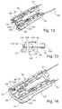
- the heating wire 130 is laid in the main body 131 corresponding to the illustration in Figure 13 . It is pointed out, merely in supplementary fashion, that the heating wire 130 is also arranged or led within the cleaning hoses 31, 32 in order to heat these as well as the cleaning arrangement 40. After the mounting of the heating wire 130 in the main body 131, it is the case, corresponding to the illustration of Figure 14 , that the closure cap 95 is connected by way of the engagement connection 96 to the main body 131 in order to close off the connecting chamber 140 or the main body 131.
- the spray body 30 is at least substantially formed over the entire length of the two cleaning hoses 31, 32 in the region of the wiper arm rod 11.
- the spray body 30 is connected to the wiper arm rod 11 by way of an engagement connection 150.
- the spray body 30 which has approximately a U-shaped cross section, has two grooves 151, 152 which run in a longitudinal direction and into which inwardly projecting sections 153, 154 of the cross section of the wiper arm rod 11 engage in positively locking fashion and fix the spray body 30 to the wiper arm rod 11 in a direction running perpendicular to its longitudinal extent.
- the spray body 30 On the underside averted from the wiper arm rod 11, the spray body 30 has in each case one mount 155 for receiving the respective cleaning hose 31, 32 in positively locking fashion, having in each case one insertion slot 156, the opening width w of which is slightly smaller than the cross section of the cleaning hose 31, 32 in the unloaded state of the cleaning hose 31, 32, such that the respective cleaning hose 31, 32 is held in the mount 155 by way of a clamping action.
- the cleaning hose 31, 32 which is formed from a plastics material as an extruded part, has the same cross section over its entire length.
- the cross section of the cleaning hose 31, 32 within the mount 155 is characterized in that the cleaning hose 31, 32 has a non-circular region 158.
- the non-circular region 158 is formed by two planar outer wall sections 159, 160 which are arranged at an angle ⁇ with respect to one another.
- Such a design of the cleaning hose 31, 32 has the effect that said cleaning hose is not only held within the mount 155 by way of a clamping action but also assumes a position with a fixed angle of rotation.
- the mount 155 thereof is furthermore of identical but inverse design with respect to the outer contour of the cleaning hose 31, 32, wherein the angle ⁇ between the two outer wall sections 159, 160 is at most 90°.
- the cleaning hoses 31, 32 have, in particular, multiple spray nozzles 162 which are arranged so as to be spaced apart from one another in the longitudinal direction at uniform intervals and which are in the form of through-openings for forming the additional spray jets 52 ( Figure 1 ).
- the spray nozzles 162 are situated in the region of the insertion slot 156.
- the spray body 30 forms a mount region 161 for the wiper blade 1 (not illustrated in Figure 15 ).
- the cleaning hoses 31, 32 are in turn connected to the cleaning arrangement 40, which has the first and second spray nozzles 42, 43 and 47, 48.
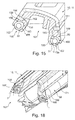
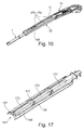
- Figures 16 to 18 illustrate further details of the wiper arm 10 or of the wiper arm rod 11 which serves as carrier element, of the spray body 30 which is designed and/or acts as an auxiliary element, and of the wiper blade 1.
- the spray body 30 has two air-guiding sections 166, 167 which extend in the longitudinal direction of the wiper arm 10 or of the wiper arm rod 11 and which are arranged parallel to one another and which project beyond the underside 168 of the wiper arm rod 11 on the side facing toward the vehicle window.
- the two air-guiding sections 166, 167 are designed to be of different heights, such that, on the front side of the wiper arm 10 or of the wiper arm rod 11 in relation to a direction of travel, the air-guiding section 166 projects further from the underside 168 of the wiper arm rod 11 or of the wiper arm 10 than the air-guiding section 167 on the rear side of the wiper arm 10. Furthermore, the two air-guiding sections 166, 167 are, at least at the regions which project from the underside 168 of the wiper arm carrier 11, arranged at an oblique angle y in relation to a vertically arranged longitudinal plane of the wiper arm 10. In a transition region 171 to the wiper arm rod 11, the two-air-guiding sections 166, 167 terminate at the outer side of the wiper arm rod 11 so as to be flush with the surface of the wiper arm rod 11.
- the spray body 30 has a substantially U-shaped cross section with a base section 172 which connects the two air-guiding sections 166, 167, wherein the base section 172 has multiple cutouts or through-openings 173 which run in the longitudinal direction of the spray body 30 and which are at least approximately rectangular.
- the through-openings 173 are aligned with openings 174 on the wiper arm carrier 11, as can be seen in particular from Figure 16 , wherein the openings 174 are of at least approximately the same size as the through-openings 173.
- FIGS 19 to 22 illustrate the guidance and fastening of the two cleaning hoses 31, 32 in the region of the wiper arm head 14 in more detail.
- the wiper arm head 14 has, in the region between the first end region 178, in which the through-opening 15 for the drive shaft is arranged, and the second end region 179, in which the wiper arm rod 11 is pivotably fastened, means for guiding the two cleaning hoses 31, 32.
- Said means comprise in particular in each case one leadthrough 181, 182 in the form of a longitudinal slot for each cleaning hose 31, 32.
- the longitudinal slot or the leadthrough 181, 182 has, as viewed toward the outer contour 185 of the wiper arm head 14, an opening 186 through which the respective cleaning hose 31, 32 can be inserted. While the cleaning hose 31, 32 is guided along the top side 187 of the wiper arm head 14 on the side facing toward the first end region 178, said cleaning hose is arranged above the underside 188 of the wiper arm head 14 on the side facing toward the second end region 179.
- the means for guiding the two cleaning hoses 31, 32 furthermore additionally have guide projections 190.
- the guide projections 190 are integrally formed on the wiper arm head 14, which is composed of aluminium (alternatively plastic) and which is in the form of an injection-moulded part, and have the effect that the two cleaning hoses 31, 32 run laterally within the outer contour 185 of the wiper arm head 14, in particular in order to also permit simple fastening of the closure cap 16 on the wiper arm head 14.
- the closure cap 16 which has substantially a U-shaped cross section, has side walls 192, 193 which terminate flush with side surfaces 194, 195 of the wiper arm head 14.
- the two leadthroughs 181, 182 are arranged offset one behind the other in relation to a longitudinal axis 191 of the wiper arm head 14.
- the second end region 179 has an eyelet 197 for forming a pivot axis 198.
- the means for guiding the cleaning hoses 31, 32 have two projections 201, 202 which, as viewed in the longitudinal direction, project beyond the eyelet 197 on the side situated opposite the first end region 178.
- a bridging spring 203 which is bent into a C shape and which in turn is connected, on the side averted from the second end region 179, to a tension spring 205 by way of which the wiper arm rod 11 is pulled together with the wiper blade 1 in the direction of the vehicle window with a pressing force.
- the wiper arm head 14 has, below the eyelet 197, a guide channel 206 for the cleaning hose 31, 32, which guide channel guides the cleaning hose 31, 32 so as to be spaced apart from the eyelet 197. It is finally pointed out that the two leadthroughs 181, 182 are arranged within the lateral outer contour 185 of the wiper arm head 14.
- the wiper device 100 thus described may be altered or modified in a variety of ways.
Landscapes
- Engineering & Computer Science (AREA)
- Mechanical Engineering (AREA)
- Water Supply & Treatment (AREA)
- Cleaning By Liquid Or Steam (AREA)
- Nozzles (AREA)
- Cleaning In General (AREA)
Applications Claiming Priority (1)
| Application Number | Priority Date | Filing Date | Title |
|---|---|---|---|
| DE102015114923.0A DE102015114923A1 (de) | 2015-09-07 | 2015-09-07 | Wischvorrichtung zum Reinigen von Fahrzeugscheiben und Reinigungseinrichtung für eine Wischvorrichtung |
Publications (1)
| Publication Number | Publication Date |
|---|---|
| EP3138747A1 true EP3138747A1 (de) | 2017-03-08 |
Family
ID=56802379
Family Applications (1)
| Application Number | Title | Priority Date | Filing Date |
|---|---|---|---|
| EP16185954.1A Withdrawn EP3138747A1 (de) | 2015-09-07 | 2016-08-26 | Wischvorrichtung zum reinigen von fahrzeugscheiben und reinigungseinrichtung für eine |
Country Status (4)
| Country | Link |
|---|---|
| US (1) | US10343652B2 (de) |
| EP (1) | EP3138747A1 (de) |
| CN (1) | CN106494357B (de) |
| DE (1) | DE102015114923A1 (de) |
Families Citing this family (3)
| Publication number | Priority date | Publication date | Assignee | Title |
|---|---|---|---|---|
| CN107139888A (zh) * | 2017-06-30 | 2017-09-08 | 博世汽车部件(长春)有限公司 | 刮水器 |
| JP7294975B2 (ja) * | 2019-09-26 | 2023-06-20 | 株式会社ミツバ | ウォッシャチューブおよびワイパアーム |
| KR102673613B1 (ko) | 2022-03-21 | 2024-06-12 | 주식회사 캐프 | 와이퍼용 체결기구, 와이퍼 블레이드 조립체 및 와이퍼 장치 |
Citations (6)
| Publication number | Priority date | Publication date | Assignee | Title |
|---|---|---|---|---|
| FR2240625A5 (en) * | 1973-08-10 | 1975-03-07 | Bosch Gmbh Robert | Washer jets for windscreen wiper blade - with directional control operated by trailing angle of pivoted blade using cylindrical valve in blade mounting |
| EP1985513A1 (de) * | 2007-04-26 | 2008-10-29 | Federal-Mogul Ignition Srl | Scheibenwischerarm |
| DE102012224474A1 (de) * | 2012-12-28 | 2014-07-03 | Robert Bosch Gmbh | Wischarmvorrichtung |
| DE102013104902A1 (de) * | 2013-05-13 | 2014-11-13 | Valeo Systèmes d'Essuyage | Wischarm für eine Scheibenwischanlage eines Kraftfahrzeugs, Wischblatt und Wischeinrichtung |
| FR3020331A1 (fr) * | 2014-04-28 | 2015-10-30 | Peugeot Citroen Automobiles Sa | Essuie-glace muni d'un dispositif de projection d'un fluide de lavage reglable en hauteur |
| EP3002166A1 (de) * | 2014-10-02 | 2016-04-06 | Valeo Systèmes d'Essuyage | Scheibenwischerarm mit einer Düse |
Family Cites Families (10)
| Publication number | Priority date | Publication date | Assignee | Title |
|---|---|---|---|---|
| US2432690A (en) * | 1943-06-25 | 1947-12-16 | Productive Inventions Inc | Windshield wiper arm and blade connector |
| FR2752798B1 (fr) * | 1996-08-27 | 1998-10-09 | Valeo Systemes Dessuyage | Essuie-glace comportant un adaptateur d'articulation |
| FR2766777B1 (fr) * | 1997-07-31 | 1999-09-03 | Valeo Systemes Dessuyage | Systeme d'essuyage d'une vitre de vehicule automobile comportant un dispositif d'arrosage perfectionne |
| DE19941499B4 (de) * | 1999-08-31 | 2018-08-16 | Robert Bosch Gmbh | Verbindungsstück zum Verbinden eines Wischblatts mit einem Wischerarm |
| GB9926679D0 (en) * | 1999-11-12 | 2000-01-12 | Trico Ltd | Improvements relating to washing units for windscreen wipers |
| DE102004007351A1 (de) * | 2004-02-16 | 2005-09-01 | Volkswagen Ag | Scheibenwischeranlage für eine Scheibe eines Fahrzeugs |
| CN100579836C (zh) * | 2007-09-24 | 2010-01-13 | 力帆实业(集团)股份有限公司 | 一种汽车雨刮装置 |
| FR2933930B1 (fr) * | 2008-07-15 | 2010-12-17 | Valeo Systemes Dessuyage | Connecteur hydraulique notamment pour systeme d'essuie-glace de vehicule automobile |
| DE102010052314A1 (de) * | 2010-11-16 | 2012-05-16 | Daimler Ag | Wischblattanordnung und Verbindungsanordnung mit einer Wischblattanordnung und einem Wischarm |
| JP5961524B2 (ja) * | 2012-10-18 | 2016-08-02 | アスモ株式会社 | 車両用ワイパ装置 |
-
2015
- 2015-09-07 DE DE102015114923.0A patent/DE102015114923A1/de active Pending
-
2016
- 2016-08-26 EP EP16185954.1A patent/EP3138747A1/de not_active Withdrawn
- 2016-09-07 CN CN201610808776.5A patent/CN106494357B/zh active Active
- 2016-09-07 US US15/258,370 patent/US10343652B2/en active Active
Patent Citations (6)
| Publication number | Priority date | Publication date | Assignee | Title |
|---|---|---|---|---|
| FR2240625A5 (en) * | 1973-08-10 | 1975-03-07 | Bosch Gmbh Robert | Washer jets for windscreen wiper blade - with directional control operated by trailing angle of pivoted blade using cylindrical valve in blade mounting |
| EP1985513A1 (de) * | 2007-04-26 | 2008-10-29 | Federal-Mogul Ignition Srl | Scheibenwischerarm |
| DE102012224474A1 (de) * | 2012-12-28 | 2014-07-03 | Robert Bosch Gmbh | Wischarmvorrichtung |
| DE102013104902A1 (de) * | 2013-05-13 | 2014-11-13 | Valeo Systèmes d'Essuyage | Wischarm für eine Scheibenwischanlage eines Kraftfahrzeugs, Wischblatt und Wischeinrichtung |
| FR3020331A1 (fr) * | 2014-04-28 | 2015-10-30 | Peugeot Citroen Automobiles Sa | Essuie-glace muni d'un dispositif de projection d'un fluide de lavage reglable en hauteur |
| EP3002166A1 (de) * | 2014-10-02 | 2016-04-06 | Valeo Systèmes d'Essuyage | Scheibenwischerarm mit einer Düse |
Also Published As
| Publication number | Publication date |
|---|---|
| US20170066418A1 (en) | 2017-03-09 |
| CN106494357A (zh) | 2017-03-15 |
| US10343652B2 (en) | 2019-07-09 |
| CN106494357B (zh) | 2020-02-14 |
| DE102015114923A1 (de) | 2017-03-09 |
Similar Documents
| Publication | Publication Date | Title |
|---|---|---|
| EP3138746B1 (de) | Reinigungseinrichtung zum reinigen von fahrzeugscheiben und wischvorrichtung | |
| EP3138742B1 (de) | Wischarmkopf für eine wischarmstange und wischarm für fahrzeugscheiben | |
| EP3138744B1 (de) | Wischvorrichtung für fahrzeugscheiben | |
| EP3138743B1 (de) | Wischvorrichtung zum reinigen von fahrzeugscheiben | |
| US10343652B2 (en) | Wiper device for cleaning vehicle windows, and cleaning arrangement for a wiper device | |
| KR20110063544A (ko) | 와이퍼 아암과 와이퍼 블레이드의 연결부 및 와이퍼 블레이드 | |
| US10449932B2 (en) | Wiper device for cleaning vehicle windows | |
| EP3138741B1 (de) | Wischarm zum reinigen einer fahrzeugscheibe | |
| JP6313655B2 (ja) | ノズル付ワイパアーム及び車両用ワイパ装置 | |
| EP3138740B1 (de) | Reinigungseinrichtung zum reinigen einer fahrzeugscheibe | |
| EP3138745B1 (de) | Wischvorrichtung zum reinigen von fahrzeugscheiben | |
| EP3196081B1 (de) | Wischvorrichtung zum reinigen einer fahrzeugscheibe und sprüheinrichtung | |
| JP2017210110A (ja) | 車両用ワイパ装置 |
Legal Events
| Date | Code | Title | Description |
|---|---|---|---|
| PUAI | Public reference made under article 153(3) epc to a published international application that has entered the european phase |
Free format text: ORIGINAL CODE: 0009012 |
|
| 17P | Request for examination filed |
Effective date: 20160826 |
|
| AK | Designated contracting states |
Kind code of ref document: A1 Designated state(s): AL AT BE BG CH CY CZ DE DK EE ES FI FR GB GR HR HU IE IS IT LI LT LU LV MC MK MT NL NO PL PT RO RS SE SI SK SM TR |
|
| AX | Request for extension of the european patent |
Extension state: BA ME |
|
| RIC1 | Information provided on ipc code assigned before grant |
Ipc: B60S 1/38 20060101AFI20180522BHEP |
|
| 17Q | First examination report despatched |
Effective date: 20180531 |
|
| GRAP | Despatch of communication of intention to grant a patent |
Free format text: ORIGINAL CODE: EPIDOSNIGR1 |
|
| INTG | Intention to grant announced |
Effective date: 20190131 |
|
| STAA | Information on the status of an ep patent application or granted ep patent |
Free format text: STATUS: THE APPLICATION IS DEEMED TO BE WITHDRAWN |
|
| 18D | Application deemed to be withdrawn |
Effective date: 20190612 |