EP3138742A2 - Wiper arm head for a wiper arm rod and wiper arm for vehicle windows - Google Patents
Wiper arm head for a wiper arm rod and wiper arm for vehicle windows Download PDFInfo
- Publication number
- EP3138742A2 EP3138742A2 EP16185949.1A EP16185949A EP3138742A2 EP 3138742 A2 EP3138742 A2 EP 3138742A2 EP 16185949 A EP16185949 A EP 16185949A EP 3138742 A2 EP3138742 A2 EP 3138742A2
- Authority
- EP
- European Patent Office
- Prior art keywords
- wiper arm
- arm head
- hose
- cleaning
- wiper
- Prior art date
- Legal status (The legal status is an assumption and is not a legal conclusion. Google has not performed a legal analysis and makes no representation as to the accuracy of the status listed.)
- Granted
Links
- 238000004140 cleaning Methods 0.000 claims abstract description 149
- 239000012530 fluid Substances 0.000 claims abstract description 14
- 239000004411 aluminium Substances 0.000 claims description 4
- 229910052782 aluminium Inorganic materials 0.000 claims description 4
- XAGFODPZIPBFFR-UHFFFAOYSA-N aluminium Chemical compound [Al] XAGFODPZIPBFFR-UHFFFAOYSA-N 0.000 claims description 4
- 230000015572 biosynthetic process Effects 0.000 claims description 2
- 238000002347 injection Methods 0.000 claims 1
- 239000007924 injection Substances 0.000 claims 1
- 239000007921 spray Substances 0.000 description 52
- 238000010438 heat treatment Methods 0.000 description 11
- 239000004033 plastic Substances 0.000 description 6
- 229920003023 plastic Polymers 0.000 description 6
- 230000007704 transition Effects 0.000 description 5
- 238000003780 insertion Methods 0.000 description 4
- 230000037431 insertion Effects 0.000 description 4
- 230000000694 effects Effects 0.000 description 3
- 230000001419 dependent effect Effects 0.000 description 2
- LIMFPAAAIVQRRD-BCGVJQADSA-N N-[2-[(3S,4R)-3-fluoro-4-methoxypiperidin-1-yl]pyrimidin-4-yl]-8-[(2R,3S)-2-methyl-3-(methylsulfonylmethyl)azetidin-1-yl]-5-propan-2-ylisoquinolin-3-amine Chemical compound F[C@H]1CN(CC[C@H]1OC)C1=NC=CC(=N1)NC=1N=CC2=C(C=CC(=C2C=1)C(C)C)N1[C@@H]([C@H](C1)CS(=O)(=O)C)C LIMFPAAAIVQRRD-BCGVJQADSA-N 0.000 description 1
- 150000001875 compounds Chemical class 0.000 description 1
- 239000000470 constituent Substances 0.000 description 1
- 230000007423 decrease Effects 0.000 description 1
- 239000007788 liquid Substances 0.000 description 1
- 239000000463 material Substances 0.000 description 1
- 229910052751 metal Inorganic materials 0.000 description 1
- 239000002184 metal Substances 0.000 description 1
- 238000000034 method Methods 0.000 description 1
- 238000005457 optimization Methods 0.000 description 1
- 238000003825 pressing Methods 0.000 description 1
Images


Classifications
-
- B—PERFORMING OPERATIONS; TRANSPORTING
- B60—VEHICLES IN GENERAL
- B60S—SERVICING, CLEANING, REPAIRING, SUPPORTING, LIFTING, OR MANOEUVRING OF VEHICLES, NOT OTHERWISE PROVIDED FOR
- B60S1/00—Cleaning of vehicles
- B60S1/02—Cleaning windscreens, windows or optical devices
- B60S1/04—Wipers or the like, e.g. scrapers
- B60S1/32—Wipers or the like, e.g. scrapers characterised by constructional features of wiper blade arms or blades
- B60S1/34—Wiper arms; Mountings therefor
- B60S1/3479—Means to cover the wiper parts
- B60S1/3481—Means to cover the wiper parts for mounting head
-
- B—PERFORMING OPERATIONS; TRANSPORTING
- B60—VEHICLES IN GENERAL
- B60S—SERVICING, CLEANING, REPAIRING, SUPPORTING, LIFTING, OR MANOEUVRING OF VEHICLES, NOT OTHERWISE PROVIDED FOR
- B60S1/00—Cleaning of vehicles
- B60S1/02—Cleaning windscreens, windows or optical devices
- B60S1/46—Cleaning windscreens, windows or optical devices using liquid; Windscreen washers
- B60S1/48—Liquid supply therefor
-
- B—PERFORMING OPERATIONS; TRANSPORTING
- B60—VEHICLES IN GENERAL
- B60S—SERVICING, CLEANING, REPAIRING, SUPPORTING, LIFTING, OR MANOEUVRING OF VEHICLES, NOT OTHERWISE PROVIDED FOR
- B60S1/00—Cleaning of vehicles
- B60S1/02—Cleaning windscreens, windows or optical devices
- B60S1/04—Wipers or the like, e.g. scrapers
- B60S1/32—Wipers or the like, e.g. scrapers characterised by constructional features of wiper blade arms or blades
- B60S1/34—Wiper arms; Mountings therefor
- B60S1/3415—Wiper arms; Mountings therefor with means for supplying cleaning fluid to windscreen cleaners, e.g. washers
-
- B—PERFORMING OPERATIONS; TRANSPORTING
- B60—VEHICLES IN GENERAL
- B60S—SERVICING, CLEANING, REPAIRING, SUPPORTING, LIFTING, OR MANOEUVRING OF VEHICLES, NOT OTHERWISE PROVIDED FOR
- B60S1/00—Cleaning of vehicles
- B60S1/02—Cleaning windscreens, windows or optical devices
- B60S1/04—Wipers or the like, e.g. scrapers
- B60S1/32—Wipers or the like, e.g. scrapers characterised by constructional features of wiper blade arms or blades
- B60S1/34—Wiper arms; Mountings therefor
- B60S1/3425—Constructional aspects of the arm
- B60S1/3436—Mounting heads
- B60S1/344—Flat-type mounting heads
-
- B—PERFORMING OPERATIONS; TRANSPORTING
- B60—VEHICLES IN GENERAL
- B60S—SERVICING, CLEANING, REPAIRING, SUPPORTING, LIFTING, OR MANOEUVRING OF VEHICLES, NOT OTHERWISE PROVIDED FOR
- B60S1/00—Cleaning of vehicles
- B60S1/02—Cleaning windscreens, windows or optical devices
- B60S1/04—Wipers or the like, e.g. scrapers
- B60S1/32—Wipers or the like, e.g. scrapers characterised by constructional features of wiper blade arms or blades
- B60S1/34—Wiper arms; Mountings therefor
- B60S1/3425—Constructional aspects of the arm
- B60S1/3445—Joints between elements
- B60S1/345—Joints between elements the elements being a link piece and a mounting head
- B60S1/3454—Joints between elements the elements being a link piece and a mounting head the joint being at end of mounting head furthest away from blade
-
- B—PERFORMING OPERATIONS; TRANSPORTING
- B60—VEHICLES IN GENERAL
- B60S—SERVICING, CLEANING, REPAIRING, SUPPORTING, LIFTING, OR MANOEUVRING OF VEHICLES, NOT OTHERWISE PROVIDED FOR
- B60S1/00—Cleaning of vehicles
- B60S1/02—Cleaning windscreens, windows or optical devices
- B60S1/46—Cleaning windscreens, windows or optical devices using liquid; Windscreen washers
- B60S1/48—Liquid supply therefor
- B60S1/52—Arrangement of nozzles; Liquid spreading means
- B60S1/522—Arrangement of nozzles; Liquid spreading means moving liquid spreading means, e.g. arranged in wiper arms
-
- B—PERFORMING OPERATIONS; TRANSPORTING
- B60—VEHICLES IN GENERAL
- B60S—SERVICING, CLEANING, REPAIRING, SUPPORTING, LIFTING, OR MANOEUVRING OF VEHICLES, NOT OTHERWISE PROVIDED FOR
- B60S1/00—Cleaning of vehicles
- B60S1/02—Cleaning windscreens, windows or optical devices
- B60S1/04—Wipers or the like, e.g. scrapers
- B60S1/0408—Means for influencing the aerodynamic quality of wipers, e.g. clip-on wind deflectors
-
- B—PERFORMING OPERATIONS; TRANSPORTING
- B60—VEHICLES IN GENERAL
- B60S—SERVICING, CLEANING, REPAIRING, SUPPORTING, LIFTING, OR MANOEUVRING OF VEHICLES, NOT OTHERWISE PROVIDED FOR
- B60S1/00—Cleaning of vehicles
- B60S1/02—Cleaning windscreens, windows or optical devices
- B60S1/04—Wipers or the like, e.g. scrapers
- B60S1/32—Wipers or the like, e.g. scrapers characterised by constructional features of wiper blade arms or blades
- B60S1/40—Connections between blades and arms
- B60S1/4038—Connections between blades and arms for arms provided with a channel-shaped end
- B60S1/4045—Connections between blades and arms for arms provided with a channel-shaped end comprising a detachable intermediate element mounted on the channel-shaped end
- B60S1/4048—Connections between blades and arms for arms provided with a channel-shaped end comprising a detachable intermediate element mounted on the channel-shaped end the element being provided with retention means co-operating with the channel-shaped end of the arm
- B60S2001/4054—Connections between blades and arms for arms provided with a channel-shaped end comprising a detachable intermediate element mounted on the channel-shaped end the element being provided with retention means co-operating with the channel-shaped end of the arm the intermediate element engaging the back part of the arm
Definitions
- the invention relates to a wiper arm head for a wiper arm rod as per the preamble of claim 1.
- the invention also relates to a wiper arm for vehicle windows using a wiper arm head according to the invention.
- a wiper arm head for a wiper arm rod as per the preamble of claim 1 is already known from practice.
- the known wiper arm head serves, in addition to its function for a pivotable arrangement of the wiper arm rod in the case of a so-called aqua-blade wiper blade, in particular also for guiding a hose which serves for the supply of a cleaning fluid to the wiper blade.
- the vehicle hose it is for example known for the vehicle hose to be arranged within the cross section of the wiper arm head, wherein the cross section of the wiper arm head forms means which effect guidance of the hose.
- What is critical in particular here is a pivoting of the wiper arm rod on the wiper arm head, in the case of which stretching of the hose occurs owing to the arrangement of the hose in the transition region between the wiper arm head and the wiper arm rod.
- the invention is based on the object of further developing a wiper arm head for a wiper arm rod as per the preamble of claim 1 such that optimized guidance of the hose in the region of the wiper arm head is realized.
- problem-free pivoting of the wiper arm rod on the wiper arm head without excessively high tensile forces acting on the hose, should also be made possible.
- the invention is based on the object of means for leading the hose being provided on the wiper arm head, wherein the means has a feedthrough which leads the hose from the upper side in the direction of an underside of the wiper arm head.
- the feedthrough is constructed in the form of a longitudinal slot.
- the longitudinal slot viewed towards the outer contour of the wiper arm head, has an opening through which the hose is able to be introduced.
- said hose is arranged on the side facing the first end region of the wiper arm head along the top side of the wiper arm head and on the side facing the second end region of the wiper arm head above the underside of the wiper arm head.
- the means for leading the hose additionally has at least one guide projection.
- guide projections are normally integrally formed on the wiper arm head which is composed of aluminium, and serve for guiding and positioning the hose on the top side of the wiper arm head.
- the cross section of the wiper arm head is weakened as little as possible, or in order to maximise the strength of the wiper arm head, it is provided that two feedthroughs are provided on opposite sides of the wiper arm head, and that the two feedthroughs are arranged offset to one another in relation to a longitudinal axis of the wiper arm head.
- a particularly well-protected arrangement of the hose in the region of the wiper arm head is made possible if the wiper arm head is covered by a covering cap, which is constructed at least substantially in a U-shape in cross-section, and the side walls of which terminate flush with side faces of the wiper arm head. In this way, it is possible for the hose to be guided within the closure or covering cap in the region of U-shaped cross section.
- a further optimization of the guidance of the hose in the region of the wiper arm head is achieved if the second end region of the wiper arm head has an eye for the formation of a pivot axis for the wiper arm rod, wherein the means has at least one extension which, viewed in longitudinal direction, project beyond the eye on the side lying opposite the first end region of the wiper arm head.
- the invention also encompasses a wiper arm for vehicle windows, comprising a wiper arm head according to the invention as described above, a wiper arm rod, and at least one hose for a cleaning fluid, directed within the wiper arm head and the wiper arm rod.
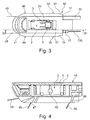
- FIG 1 illustrates, in a perspective illustration, a wiper device 100 for cleaning a vehicle window (not shown), in particular a front window of the vehicle.
- the wiper device 100 has a wiper blade 1 which is in particular in the form of a so-called flat wiper blade.
- the wiper blade 1 is fastened exchangeably to a wiper arm 10.
- the wiper arm 10 comprises an elongate wiper arm rod 11 which is composed of metal or plastic and which acts as a carrier element and which is fastened pivotably, by way of a pin 12 and a sleeve 13 ( Figure 2 ), to a wiper arm head 14, which is composed in particular of aluminium (alternatively plastic).
- the wiper arm head 14 has, on the side averted from the wiper arm carrier 11, a through-opening 15 for the purposes of fastening the wiper arm head 14 rotationally conjointly to a wiper shaft (not shown) which is connected at least indirectly to a wiper bearing or to a wiper motor.
- the wiper arm head 14 is mounted so as to be pivotable about a wiper arm axis 17 and is, at least in the region of the through-opening 15, covered by a covering cap 16.
- the wiper arm rod 11 has, over its entire length, a substantially U-shaped cross section with a top side 18 and with two side walls 19, 20 which project approximately at right angles from the top side 18 in the direction of the vehicle window.
- said wiper arm rod forms, on the side averted from the wiper arm head 14, a mount or a first mount region 21 for the fastening of the wiper blade 1, this being adjoined in the direction of the wiper arm head 14 by a second mount region 22.
- An elongated moulded part which is composed of plastic and which is in the form of a spray body 30 is arranged within the second mount region 22.
- the spray body 30 laterally terminates approximately flush with the two side walls 19, 20 of the wiper arm carrier 11. Furthermore, the spray body 30 projects, below the two side walls 19, 20, out of the second mount region 22 of the wiper arm rod 11.
- the spray body 30 there are arranged two cleaning hoses 31, 32 ( Figure 2 ) which serve for the supply of cleaning fluid.
- the two cleaning hoses 31, 32 are arranged within the spray body 30 on opposite longitudinal sides of the wiper blade 1.
- a cleaning arrangement 40 which is in the form of a separate component composed of plastic.
- the cleaning arrangement 40 is arranged on that end region of the wiper arm rod 11 or of the wiper arm 10 which is averted from the wiper arm head 14.
- the fastening of the cleaning arrangement 40 within the first mount region 21 of the wiper arm rod 11 may be realized in a variety of ways, as will be discussed in more detail below.
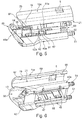
- the cleaning arrangement 40 has, on the side averted from the wiper arm head 14, a front end face 41 which simultaneously forms an end face of the wiper arm 10.
- a front end face 41 which simultaneously forms an end face of the wiper arm 10.
- two first spray nozzles 42, 43 whose spray jets 45, 46, which can be seen in Figures 3 and 4 , are oriented so as to be inclined at an angle with respect to the longitudinal direction of the wiper arm carrier 11 in the direction of the vehicle window. It is furthermore essential that the two first spray nozzles 42, 43 are arranged such that the spray jets 45, 46 can apply the cleaning fluid to the vehicle window in front of different longitudinal sides of the wiper blade 1.
- the cleaning arrangement 40 has, in the region of its opposite longitudinal sides, in each case two second spray nozzles 47, 48 for the cleaning fluid, which spray nozzles generate spray jets 49, 50 which are likewise oriented at an angle with respect to the longitudinal axis of the wiper arm rod 11 in the direction of the vehicle window, wherein the orientation is furthermore in the direction of the side averted from the wiper arm head 14.
- the cleaning arrangement 40 For the supply of the cleaning fluid to the cleaning arrangement 40 via the cleaning hoses 31, 32, the cleaning arrangement 40 has, on the side facing toward the wiper arm head 14 and in the region of its two longitudinal sides, in each case one feed connector 51, onto which the respective cleaning hose 31, 32 is pushed. Furthermore, the two cleaning hoses 31, 32 have, as can be seen in particular when viewing Figure 1 and Figure 15 together, spray nozzles 162 for generating additional spray jets 52 which are likewise directed toward the vehicle window and which strike the vehicle window on both sides of the wiper blade 1.
- a cleaning arrangement 40 as described up to this point makes it possible, together with the two cleaning hoses 31, 32, and by way of a supply of cleaning fluid which is controlled in a manner dependent on the wiping direction 53 of the wiper blade 1, for cleaning fluid to be applied to the vehicle window in each case in front of the longitudinal side of the wiper blade 1 in the movement direction of the wiper blade 1.
- the cleaning arrangement 40 has two side walls 54, 55 ( Figure 3 ) which, at least in certain regions, run flush with the inner sides of the side walls 19, 20 of the wiper arm rod 11 in the region of the first mount region 21. Furthermore, the cleaning arrangement 40 has a through-opening 57.
- the cleaning arrangement 40 forms an additional mount region 58 which is of approximately U-shaped form in cross section and which has an aperture in the region of the through-opening 57.
- the cleaning arrangement 40 which is received within the wiper arm 10 or the first mount region 21 serves for the fastening of the wiper blade 1.
- the wiper blade 1 has a wiper blade adapter, only certain areas of which are illustrated in the figures, and which has a fastening arrangement 2.
- the fastening arrangement 2 has, on the side facing toward the top side 18 of the first mount region 21, a spring tongue 3 with an engagement button 4 which, in the mounted state of the wiper blade 1 or of the fastening arrangement 2 on the wiper arm 10, engages in positively locking fashion into an opening 5 formed in the top side 18 of the wiper arm 10.
- the engagement button 4 forms, together with the opening 5, an engagement connection between the wiper blade 1 and the wiper arm 10, by way of which engagement connection the wiper blade 1 or the fastening arrangement 2 is secured on the wiper arm 10, wherein, after the engagement connection has been released, the wiper blade 1 can be dismounted from the wiper arm 10, in particular in order to permit an exchange of the wiper blade 1.
- both the fastening arrangement 2 and the cleaning arrangement 40 are arranged, at least in certain areas, within the first mount region 21 of the wiper arm 10 or of the wiper arm rod 11. Furthermore, in the mounted state of the fastening arrangement 2, the additional mount region 58 of the cleaning arrangement 40 encompasses the fastening arrangement 2, whereas the first mount region 21 of the wiper arm 10 encompasses the cleaning arrangement 40.
- the cleaning arrangement 40 is, on the side facing toward the spray body 30, laterally covered in certain areas by the spray body 30, for example by way of two lugs 59, 60 arranged on the spray body 30 on the longitudinal sides thereof.
- Figure 23 shows the fastening arrangement 2 before the mounting thereof on the cleaning arrangement 40.
- the fastening arrangement 2 is moved relative to the cleaning arrangement 40 in the direction of a first mounting direction 61, which runs perpendicular to the longitudinal direction of the wiper arm 10.
- Figures 24 and 25 illustrate the state in which the fastening arrangement 2 is arranged within the additional mount region 58 of the cleaning arrangement 40 and, there, can be moved no further in the direction of the first mounting direction 61.
- a relative movement of the fastening arrangement 2 with respect to the cleaning arrangement 40 is performed in the direction of a second mounting direction 62 ( Figure 24 ), wherein the second mounting direction 62 runs perpendicular to the first mounting direction 61.
- the fastening arrangement 2 is (fully) mounted on the cleaning arrangement 40, wherein, at the same time, the engagement button 4 of the fastening arrangement 2 is engaged with the opening 5 on the top side 18 of the wiper arm 10 (not shown).
- the fastening arrangement 2 and the cleaning arrangement 40 have first and second guide means 65, 66 which cooperate with one another.
- the first guide means 65 are for example formed, in the form of first elevations 71 and second elevations 72, in the region of the cleaning arrangement 40, on the inner side of the two side walls 54, 55, which are arranged parallel to one another, of the cleaning arrangement 40.
- the first elevations 71 are formed in the form of cams which, in the region of a lower edge 73 of the cleaning arrangement 40, are arranged with a spacing A to one another.
- the second elevation 72 is arranged in the region of a top edge 74 of the cleaning arrangement 40 and has an elongated shape.
- the second elevation 72 which is arranged between the two first elevations 71 as viewed in the longitudinal direction of the cleaning arrangement 40, simultaneously serves as an axial abutment for the fastening arrangement 2 when the latter is inserted into the cleaning arrangement 40 in the direction of the first mounting direction 61.
- the first elevations 71 on the cleaning arrangement 40 cooperate with in each case one depression 75, 76 as second guide means 66, which are formed on in each case an outer side of a side wall 67, 68 of the fastening arrangement 2.
- the two depressions 75, 76 have in each case a width B slightly larger than a width b of the two first elevations 71, such that, in the position of the fastening arrangement 2 illustrated in Figure 24 , there is movement play 77 in the cleaning arrangement 40 in the direction of the second mounting direction 62.
- the depressions 75, 76 transition, in the direction of the top side, which faces toward the spring tongue 3, of the fastening arrangement 2, into an elongated depression 78.
- the first and second guide means 65, 66 serve, during the mounting process, to guide the fastening arrangement 2 between the starting position 80 illustrated in Figure 24 and the end position 81 illustrated in Figure 25 . Furthermore, by way of corresponding geometric dimensioning of the guide means 65, 66, it is ensured that the movement play 77 that is initially provided in the starting position 80 is reduced to zero in the end position 81, that is to say the fastening arrangement 2 is, in the end position 81, received without play within the cleaning arrangement 40. By way of the discussed geometric dimensioning, it is the case here that the movement play 77 decreases preferably in continuous fashion between the starting position 80 and the end position 81.
- the fastening arrangement 2 which is part of the wiper blade adapter (not illustrated) for the fastening of the wiper blade 1 to the wiper arm 10, has an opening 82 which forms an axis of rotation 83, with the wiper blade 1 being mounted in the fastening arrangement 2 so as to be pivotable about said axis of rotation.
- the first elevations 71 are, in relation to the additional mount region 58 in the cleaning arrangement 40 or in relation to the depressions 75, 76 of the fastening arrangement 2, arranged at corner regions of the fastening arrangement 2 and of the cleaning arrangement 40, wherein the axis of rotation 83 is arranged between the first elevations 71.
- the projections 89, 90 cooperate with cutouts 91, 92 formed on the cleaning arrangement 40a.
- the cutouts 91 formed in the region of the side walls 54a, 55a of the cleaning arrangement 40a are situated in an approximately central region in relation to the longitudinal extent of the cleaning arrangement 40a
- the cutouts 92 are arranged on the side averted from the front face end face 41 a, and terminate with an end face 93.
- the cutouts 91 are of L-shaped form
- the cutouts 92 are in the form of elongated cutouts.
- a bayonet connection 88 of said type enables the cleaning arrangement 40a to be mounted on the wiper arm 10a by virtue, for example, of the wiper arm 10a firstly being connected to the cleaning arrangement 40a in the direction of the first mounting direction 61 a, wherein the projections 89 engage into the vertical part of the cutouts 91.
- the projections 89 bear against the underside of the cutouts 91, a movement of the wiper arm 10a takes place in the direction of the second mounting direction 62a, wherein the projections 89, 90 cooperate with the cutouts 91, 92 which are each oriented or arranged in the longitudinal direction of the cleaning arrangement 40a.
- the relative movement between the wiper arm 10a and the cleaning arrangement 40a is limited by virtue of the projections 89, 90 bearing in each case against those delimitations of the cutouts 91, 92 which face toward the end face 41 a.
- the rear side 94 of a covering cap 95 which is connected by way of an engagement connection 96 to the cleaning arrangement 40a is still arranged with a minimal spacing to the front end face 97 of the wiper arm 10a.
- an engagement cam 87 is arranged with resilient action in the vertical section of the cutout 91.
- the engagement cam 87 projects into the movement travel of the projection 89 and is pushed inward by said projection during the insertion into the cutout 91.
- the engagement cam 87 springs back into its original position and forms an abutment for the projection 89 in the event of a movement of the cleaning arrangement 40a counter to the direction of the mounting direction 62a.
- Figure 7 illustrates the situation in which the wiper arm 10b is connected to the cleaning arrangement 40b by way of an engagement connection 98.
- the two side walls 54b, 55b of the cleaning arrangement 40b have, in their upper region, in each case two engagement cams 99 which are spaced apart from one another axially in relation to the longitudinal direction of the cleaning arrangement 40b and which, from the position illustrated in Figure 7 , are elastically deformable for example into a position offset in the direction of the side walls 54b, 55b.
- the wiper arm 10b In the region of the wiper arm 10b, the latter has, on the inner side of the two side walls 19, 20, projections which are arranged, in Figure 5 , in overlap with the engagement cams 99 (analogously to the projections 89, 90 in the case of the wiper arm 10a) and which, during the relative movement of the wiper arm 10b in the direction of the mounting direction 101 toward the cleaning arrangement 40b, cause the engagement cams 99 to be pushed in and to subsequently be locked to the wiper arm 10b.
- the engagement connection 102 illustrated in Figure 8 differs from the engagement connection 98 in that, on the cleaning arrangement 40c, in the region of the two side walls 54c, 55c, there are respectively arranged elongated barbs 103 which, in forming the engagement connection 102, cooperate with the projections arranged in the region of the wiper arm 10c in such a way that the engagement connection 102 can no longer be released again.
- Figure 9 illustrates the situation in which the cleaning arrangement 40d is connected to the wiper arm 10d by way of a positively locking connection 105.
- the positively locking connection 105 has, on the wiper arm 10d, elongated projections or guide elements 106, 107 which project inward from the side walls 19, 20 of said wiper arm and which cooperate with counterpart elements in the form of groove-like, elongated cutouts 108 in the region of the two side walls 54d, 55d of the cleaning arrangement 40d.
- the cleaning arrangement 40d is inserted by way of a linear movement into the (open) cross section of the first mount region 21 of the wiper arm 10d in the direction of the mounting direction 109, wherein the guide elements 106, 107 pass into the cutouts 108 and, in so doing, fix the cleaning arrangement 40d in a direction running perpendicular to the mounting direction 109.
- the axial movement or the sliding-in movement of the cleaning arrangement 40d is likewise limited by the rear side 94 of the covering cap 95.
- an engagement connection may be formed between the cleaning arrangement 40d and, for example, the spray body 30, for which purpose, for example, the cleaning arrangement 40d has engagement hooks 110.
- the wiper blade 1 in particular the wiper blade body 115 thereof, is connected by way of a wiper blade adapter to the wiper arm 10 or to the cleaning arrangement 40, which, aside from the fastening arrangement 2, has an adapter element 116 which is fastened to the wiper blade body 115 and which is pivotably connected to the fastening arrangement 2 in the region of the through-opening 57 of the fastening arrangement 2.
- the adapter element 116 has a length Y as viewed in the longitudinal direction of the wiper blade 1.
- the wiper arm 10 in particular the cleaning arrangement 40, has two elongated cutouts 118, 119 which can be seen in Figure 11 .
- the two cutouts 118, 119 each have a length X slightly greater than the length Y of the adapter element 116.
- the adapter element 116 projects into the two cutouts 118, 119.
- the two cutouts 118, 119 each have an at least substantially constant cross section.
- Figure 10 shows a connecting duct 121 which connects a feed connector 51 to a first spray nozzle 42 or 43.
- the connecting duct 121 runs, in the region of the cutout 118, 119, at least approximately parallel to the cutout 118, 119 and is hydraulically connected to the respective first spray nozzle 42, 43 and to the respective feed connector 51 by way of a section 122 of curved form.
- the two side walls 54, 55 of the cleaning arrangement 40 are, on both sides of the cutouts 118, 119, connected to one another by way of two transverse connecting elements 124, 125 which permit stiffening of the cleaning arrangement 40, wherein the two transverse connecting elements 124, 125 are arranged outside the further mount region 58 for the fastening arrangement 2 or the adapter element 116.
- the cleaning arrangement 40 has a main body 131 which is connected by way of the covering cap 95, as already described above, by way of the engagement connection 98.
- the engagement connection 98 has, on the covering cap 95, an engagement hook 132 which, in the locking position, cooperates with two counterpart engagement elements 133, 134 arranged on both sides of the engagement hook 132.
- the covering cap 95 serves, in the installed state of the cleaning arrangement 40 on the wiper arm 10, to close off, in a surface-flush manner, the first mount region 21, which is open at the end side, of the wiper arm 10.
- the two feed connectors 51 are connected to the respective first spray nozzle 42, 43 by way of the connecting duct 121.
- the connecting duct 121 From the connecting duct 121, in the transition region to the section 122, there extends in each case one branch 135 with a section 137, wherein the section 137 forms a rectilinear elongation of a longitudinal axis 136 of the connecting duct 121.
- the section 122 runs at an angle ⁇ with respect to the longitudinal axis 136.
- the section 137 On the side averted from the branch 135, the section 137 has a mouth region 139 which opens out within a connecting chamber 140 formed between the covering cap 95 and the main body 131.
- the section 137 or the mouth region 139 furthermore forms a feed port 141 in the connecting chamber 140.
- the (single) heating wire 130 is led at least substantially horizontally.
- the heating wire 130 is, in the region of the connecting chamber 140, arranged in the form of a loop 142 below the two counterpart engagement elements 133, 134, in order to make it possible for the engagement hook 132 to interact, without making contact with the heating wire 130, with the two counterpart engagement elements 133, 134.
- a seal element 143 or a seal compound 144 is arranged within the respective mouth region 139.
- the connecting chamber 140 itself is also hydraulically sealed off to the outside by way of corresponding measures.
- the feed port 141 is of tubular form, or has a hollow cross section, in the region of the connecting chamber 140.
- the heating wire 130 is laid in the main body 131 corresponding to the illustration in Figure 13 . It is pointed out, merely in supplementary fashion, that the heating wire 130 is also arranged or led within the cleaning hoses 31, 32 in order to heat these as well as the cleaning arrangement 40. After the mounting of the heating wire 130 in the main body 131, it is the case, corresponding to the illustration of Figure 14 , that the covering cap 95 is connected by way of the engagement connection 96 to the main body 131 in order to close off the connecting chamber 140 or the main body 131.
- the spray body 30 is at least substantially formed over the entire length of the two cleaning hoses 31, 32 in the region of the wiper arm rod 11.
- the spray body 30 is connected to the wiper arm rod 11 by way of an engagement connection 150.
- the spray body 30 which has approximately a U-shaped cross section, has two grooves 151, 152 which run in a longitudinal direction and into which inwardly projecting sections 153, 154 of the cross section of the wiper arm rod 11 engage in positively locking fashion and fix the spray body 30 to the wiper arm rod 11 in a direction running perpendicular to its longitudinal extent.
- the spray body 30 On the underside averted from the wiper arm rod 11, the spray body 30 has in each case one mount 155 for receiving the respective cleaning hose 31, 32 in positively locking fashion, having in each case one insertion slot 156, the opening width w of which is slightly smaller than the cross section of the cleaning hose 31, 32 in the unloaded state of the cleaning hose 31, 32, such that the respective cleaning hose 31, 32 is held in the mount 155 by way of a clamping action.
- the cleaning hose 31, 32 which is formed from a plastics material as an extruded part, has the same cross section over its entire length.
- the cross section of the cleaning hose 31, 32 within the mount 155 is characterized in that the cleaning hose 31, 32 has a non-circular region 158.
- the non-circular region 158 is formed by two planar outer wall sections 159, 160 which are arranged at an angle ⁇ with respect to one another.
- Such a design of the cleaning hose 31, 32 has the effect that said cleaning hose is not only held within the mount 155 by way of a clamping action but also assumes a position with a fixed angle of rotation.
- the mount 155 thereof is furthermore of identical but inverse design with respect to the outer contour of the cleaning hose 31, 32, wherein the angle ⁇ between the two outer wall sections 159, 160 is at most 90°.
- the cleaning hoses 31, 32 have, in particular, multiple spray nozzles 162 which are arranged so as to be spaced apart from one another in the longitudinal direction at uniform intervals and which are in the form of through-openings for forming the additional spray jets 52 ( Figure 1 ).
- the spray nozzles 162 are situated in the region of the insertion slot 156.
- the spray body 30 forms a mount region 161 for the wiper blade 1 (not illustrated in Figure 15 ).
- the cleaning hoses 31, 32 are in turn connected to the cleaning arrangement 40, which has the first and second spray nozzles 42, 43 and 47, 48.
- Figures 16 to 18 illustrate further details of the wiper arm 10 or of the wiper arm rod 11 which serves as carrier element, of the spray body 30 which is designed and/or acts as an auxiliary element, and of the wiper blade 1.
- the spray body 30 has two air-guiding sections 166, 167 which extend in the longitudinal direction of the wiper arm 10 or of the wiper arm rod 11 and which are arranged parallel to one another and which project beyond the underside 168 of the wiper arm rod 11 on the side facing toward the vehicle window.
- the two air-guiding sections 166, 167 are designed to be of different heights, such that, on the front side of the wiper arm 10 or of the wiper arm rod 11 in relation to a direction of travel, the air-guiding section 166 projects further from the underside 168 of the wiper arm rod 11 or of the wiper arm 10 than the air-guiding section 167 on the rear side of the wiper arm 10. Furthermore, the two air-guiding sections 166, 167 are, at least at the regions which project from the underside 168 of the wiper arm carrier 11, arranged at an oblique angle ⁇ in relation to a vertically arranged longitudinal plane of the wiper arm 10. In a transition region 171 to the wiper arm rod 11, the two-air-guiding sections 166, 167 terminate at the outer side of the wiper arm rod 11 so as to be flush with the surface of the wiper arm rod 11.
- the spray body 30 has a substantially U-shaped cross section with a base section 172 which connects the two air-guiding sections 166, 167, wherein the base section 172 has multiple cutouts or through-openings 173 which run in the longitudinal direction of the spray body 30 and which are at least approximately rectangular.
- the through-openings 173 are aligned with openings 174 on the wiper arm carrier 11, as can be seen in particular from Figure 16 , wherein the openings 174 are of at least approximately the same size as the through-openings 173.
- FIGS 19 to 22 illustrate the guidance and fastening of the two cleaning hoses 31, 32 in the region of the wiper arm head 14 in more detail.
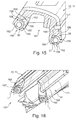
- the wiper arm head 14 has, in the region between the first end region 178, in which the through-opening 15 for the drive shaft is arranged, and the second end region 179, in which the wiper arm rod 11 is pivotably fastened, means for guiding the two cleaning hoses 31, 32.
- Said means comprise in particular in each case one leadthrough 181, 182 in the form of a longitudinal slot for each cleaning hose 31, 32.
- the longitudinal slot or the leadthrough 181, 182 has, as viewed toward the outer contour 185 of the wiper arm head 14, an opening 186 through which the respective cleaning hose 31, 32 can be inserted. While the cleaning hose 31, 32 is guided along the top side 187 of the wiper arm head 14 on the side facing toward the first end region 178, said cleaning hose is arranged above the underside 188 of the wiper arm head 14 on the side facing toward the second end region 179.
- the means for guiding the two cleaning hoses 31, 32 furthermore additionally have guide projections 190.
- the guide projections 190 are integrally formed on the wiper arm head 14, which is composed of aluminium (alternatively plastic) and which is in the form of an injection-moulded part, and have the effect that the two cleaning hoses 31, 32 run laterally within the outer contour 185 of the wiper arm head 14, in particular in order to also permit simple fastening of the covering cap 16 on the wiper arm head 14.
- the covering cap 16 which has substantially a U-shaped cross section, has side walls 192, 193 which terminate flush with side surfaces 194, 195 of the wiper arm head 14.
- the two leadthroughs 181, 182 are arranged offset one behind the other in relation to a longitudinal axis 191 of the wiper arm head 14.
- the second end region 179 has an eyelet 197 for forming a pivot axis 198.
- the means for guiding the cleaning hoses 31, 32 have two projections 201, 202 which, as viewed in the longitudinal direction, project beyond the eyelet 197 on the side situated opposite the first end region 178.
- a bridging spring 203 which is bent into a C shape and which in turn is connected, on the side averted from the second end region 179, to a tension spring 205 by way of which the wiper arm rod 11 is pulled together with the wiper blade 1 in the direction of the vehicle window with a pressing force.
- the wiper arm head 14 has, below the eyelet 197, a guide channel 206 for the cleaning hose 31, 32, which guide channel guides the cleaning hose 31, 32 so as to be spaced apart from the eyelet 197. It is finally pointed out that the two leadthroughs 181, 182 are arranged within the lateral outer contour 185 of the wiper arm head 14.
- the wiper device 100 thus described may be altered or modified in a variety of ways.
Landscapes
- Engineering & Computer Science (AREA)
- Mechanical Engineering (AREA)
- Water Supply & Treatment (AREA)
- Ink Jet (AREA)
- Transmission Devices (AREA)
- Cleaning Implements For Floors, Carpets, Furniture, Walls, And The Like (AREA)
- Cleaning In General (AREA)
Abstract
Description
- The invention relates to a wiper arm head for a wiper arm rod as per the preamble of
claim 1. The invention also relates to a wiper arm for vehicle windows using a wiper arm head according to the invention. - A wiper arm head for a wiper arm rod as per the preamble of
claim 1 is already known from practice. The known wiper arm head serves, in addition to its function for a pivotable arrangement of the wiper arm rod in the case of a so-called aqua-blade wiper blade, in particular also for guiding a hose which serves for the supply of a cleaning fluid to the wiper blade. For this purpose, it is for example known for the vehicle hose to be arranged within the cross section of the wiper arm head, wherein the cross section of the wiper arm head forms means which effect guidance of the hose. What is critical in particular here is a pivoting of the wiper arm rod on the wiper arm head, in the case of which stretching of the hose occurs owing to the arrangement of the hose in the transition region between the wiper arm head and the wiper arm rod. - Proceeding from the presented prior art, the invention is based on the object of further developing a wiper arm head for a wiper arm rod as per the preamble of
claim 1 such that optimized guidance of the hose in the region of the wiper arm head is realized. In particular, problem-free pivoting of the wiper arm rod on the wiper arm head, without excessively high tensile forces acting on the hose, should also be made possible. - Said object is achieved according to the invention with a wiper arm head for a wiper arm rod having the features of
claim 1. - Here, the invention is based on the object of means for leading the hose being provided on the wiper arm head, wherein the means has a feedthrough which leads the hose from the upper side in the direction of an underside of the wiper arm head.
- Advantageous refinements of the wiper arm head according to the invention for a wiper arm rod are specified in the subclaims. The scope of the invention encompasses all combinations of at least two features disclosed in the claims, in the description and/or in the figures.
- In order, in the leading of the hose from the upper side in the direction of the underside of the wiper arm head, to be able to realize as large as possible a bend radius or the least possible deformation of the hose, it is provided that the feedthrough is constructed in the form of a longitudinal slot.
- To make it possible for the hose to be installed into the region of the feedthrough or into the region of the longitudinal slot as easily as possible, it is provided that the longitudinal slot, viewed towards the outer contour of the wiper arm head, has an opening through which the hose is able to be introduced.
- In a preferred arrangement of the hose, it is provided that said hose is arranged on the side facing the first end region of the wiper arm head along the top side of the wiper arm head and on the side facing the second end region of the wiper arm head above the underside of the wiper arm head. By virtue of the fact that the hose is led above the underside of the wiper arm head, a relatively small spacing is formed between the hose and a pivot axis of the wiper arm rod on the wiper arm head, which makes it possible for the hose to be guided entirely within the contour of the wiper arm head.
- In a preferred design refinement of the invention, it is provided that the means for leading the hose additionally has at least one guide projection. Such guide projections are normally integrally formed on the wiper arm head which is composed of aluminium, and serve for guiding and positioning the hose on the top side of the wiper arm head.
- In order that, despite the provision of the longitudinal slots, the cross section of the wiper arm head is weakened as little as possible, or in order to maximise the strength of the wiper arm head, it is provided that two feedthroughs are provided on opposite sides of the wiper arm head, and that the two feedthroughs are arranged offset to one another in relation to a longitudinal axis of the wiper arm head.
- A particularly well-protected arrangement of the hose in the region of the wiper arm head is made possible if the wiper arm head is covered by a covering cap, which is constructed at least substantially in a U-shape in cross-section, and the side walls of which terminate flush with side faces of the wiper arm head. In this way, it is possible for the hose to be guided within the closure or covering cap in the region of U-shaped cross section.
- A further optimization of the guidance of the hose in the region of the wiper arm head is achieved if the second end region of the wiper arm head has an eye for the formation of a pivot axis for the wiper arm rod, wherein the means has at least one extension which, viewed in longitudinal direction, project beyond the eye on the side lying opposite the first end region of the wiper arm head.
- Finally, the invention also encompasses a wiper arm for vehicle windows, comprising a wiper arm head according to the invention as described above, a wiper arm rod, and at least one hose for a cleaning fluid, directed within the wiper arm head and the wiper arm rod.
- Further advantages, features and details of the invention will emerge from the following description of a preferred exemplary embodiments and on the basis of the drawing.
- In the drawing:
-
Figure 1 shows a wiper device for cleaning vehicle windows in a perspective view, -
Figure 2 shows the constituent parts of the cleaning arrangement as perFigure 1 in a perspective exploded illustration, -
Figure 3 shows the region between a fastening arrangement for the wiper blade and a cleaning arrangement of the wiper device in a plan view, -
Figure 4 shows a view in the direction of the arrows IV-IV ofFigure 3 , -
Figure 5 and
Figure 6 each show, in different perspective views, the cleaning arrangement and a subregion of the wiper arm in the case of a connection between the cleaning arrangement and the wiper arm by way of a bayonet connection, -
Figure 7 and
Figure 8 each show a subregion of the wiper arm and a cleaning arrangement, wherein the cleaning arrangement is connected to the wiper arm by way of an engagement connection, in each case in a perspective view, -
Figure 9 shows a perspective view of a cleaning arrangement and of a subregion of a wiper arm, in the case of which the cleaning arrangement is slid into the wiper arm, -
Figure 10 shows the fastening region of the wiper blade to the wiper arm in a perspective illustration, -
Figure 11 shows a view from below of the cleaning arrangement ofFigure 10 in a perspective illustration, -
Figure 12 shows the cleaning arrangement in a further perspective illustration, wherein the cleaning arrangement can be closed by way of a separate covering cap, -
Figure 13 is an illustration, in longitudinal section, of ducts which are arranged in the cleaning arrangement as perFigure 12 for the purposes of guiding a heating wire, -
Figure 14 shows the cleaning arrangement as perFigure 12 with covering cap mounted thereon in a perspective view, -
Figure 15 shows a cross section through the wiper arm in the region of two liquid hoses with spray openings formed therein, -
Figure 16 shows the wiper device as perFigure 1 in a further, partially sectional or cutaway perspective illustration, -
Figure 17 shows, in a perspective detail illustration, an auxiliary element in the form of a spray body arranged within the wiper arm, -
Figure 18 shows a cross section through the region of the wiper arm as perFigure 16 , -
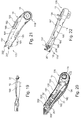
Figure 19 is an illustration of the wiper arm head of the wiper arm, -
Figure 20 shows a view from below of the wiper arm head as perFigure 19 in a perspective illustration, -
Figure 21 and
Figure 22 show the wiper arm head in each case in a perspective illustration from different perspectives, and -
Figure 23 to
Figure 25 show a part of the fastening arrangement of the wiper blade and the cleaning arrangement in a perspective illustration during various mounting steps. - Identical elements or elements of identical function are denoted in the figures by the same reference designations.
-
Figure 1 illustrates, in a perspective illustration, awiper device 100 for cleaning a vehicle window (not shown), in particular a front window of the vehicle. Thewiper device 100 has awiper blade 1 which is in particular in the form of a so-called flat wiper blade. Thewiper blade 1 is fastened exchangeably to awiper arm 10. Thewiper arm 10 comprises an elongatewiper arm rod 11 which is composed of metal or plastic and which acts as a carrier element and which is fastened pivotably, by way of apin 12 and a sleeve 13 (Figure 2 ), to awiper arm head 14, which is composed in particular of aluminium (alternatively plastic). Thewiper arm head 14 has, on the side averted from thewiper arm carrier 11, a through-opening 15 for the purposes of fastening thewiper arm head 14 rotationally conjointly to a wiper shaft (not shown) which is connected at least indirectly to a wiper bearing or to a wiper motor. Thewiper arm head 14 is mounted so as to be pivotable about awiper arm axis 17 and is, at least in the region of the through-opening 15, covered by acovering cap 16. - The
wiper arm rod 11 has, over its entire length, a substantially U-shaped cross section with atop side 18 and with twoside walls top side 18 in the direction of the vehicle window. As viewed in the longitudinal direction of thewiper arm rod 11, said wiper arm rod forms, on the side averted from thewiper arm head 14, a mount or afirst mount region 21 for the fastening of thewiper blade 1, this being adjoined in the direction of thewiper arm head 14 by asecond mount region 22. An elongated moulded part which is composed of plastic and which is in the form of aspray body 30 is arranged within thesecond mount region 22. As can be seen fromFigure 1 , thespray body 30 laterally terminates approximately flush with the twoside walls wiper arm carrier 11. Furthermore, thespray body 30 projects, below the twoside walls second mount region 22 of thewiper arm rod 11. - Furthermore, within the
second mount region 22, in particular within the cross section of thespray body 30, there are arranged twocleaning hoses 31, 32 (Figure 2 ) which serve for the supply of cleaning fluid. The twocleaning hoses spray body 30 on opposite longitudinal sides of thewiper blade 1. - Within the
first mount region 21 of thewiper arm rod 11, there is received acleaning arrangement 40 which is in the form of a separate component composed of plastic. In particular, the cleaningarrangement 40 is arranged on that end region of thewiper arm rod 11 or of thewiper arm 10 which is averted from thewiper arm head 14. The fastening of thecleaning arrangement 40 within thefirst mount region 21 of thewiper arm rod 11 may be realized in a variety of ways, as will be discussed in more detail below. - The cleaning
arrangement 40 has, on the side averted from thewiper arm head 14, a front end face 41 which simultaneously forms an end face of thewiper arm 10. By way of example, in the region of thefront end face 41, there are arranged twofirst spray nozzles spray jets Figures 3 and 4 , are oriented so as to be inclined at an angle with respect to the longitudinal direction of thewiper arm carrier 11 in the direction of the vehicle window. It is furthermore essential that the twofirst spray nozzles spray jets wiper blade 1. Furthermore, by way of example, the cleaningarrangement 40 has, in the region of its opposite longitudinal sides, in each case twosecond spray nozzles spray jets wiper arm rod 11 in the direction of the vehicle window, wherein the orientation is furthermore in the direction of the side averted from thewiper arm head 14. - For the supply of the cleaning fluid to the
cleaning arrangement 40 via thecleaning hoses arrangement 40 has, on the side facing toward thewiper arm head 14 and in the region of its two longitudinal sides, in each case onefeed connector 51, onto which therespective cleaning hose cleaning hoses Figure 1 andFigure 15 together,spray nozzles 162 for generatingadditional spray jets 52 which are likewise directed toward the vehicle window and which strike the vehicle window on both sides of thewiper blade 1. A cleaningarrangement 40 as described up to this point makes it possible, together with the twocleaning hoses direction 53 of thewiper blade 1, for cleaning fluid to be applied to the vehicle window in each case in front of the longitudinal side of thewiper blade 1 in the movement direction of thewiper blade 1. - The cleaning
arrangement 40 has twoside walls 54, 55 (Figure 3 ) which, at least in certain regions, run flush with the inner sides of theside walls wiper arm rod 11 in the region of thefirst mount region 21. Furthermore, the cleaningarrangement 40 has a through-opening 57. The cleaningarrangement 40 forms anadditional mount region 58 which is of approximately U-shaped form in cross section and which has an aperture in the region of the through-opening 57. In particular, the cleaningarrangement 40 which is received within thewiper arm 10 or thefirst mount region 21 serves for the fastening of thewiper blade 1. For this purpose, thewiper blade 1 has a wiper blade adapter, only certain areas of which are illustrated in the figures, and which has afastening arrangement 2. - The
fastening arrangement 2 has, on the side facing toward thetop side 18 of thefirst mount region 21, aspring tongue 3 with anengagement button 4 which, in the mounted state of thewiper blade 1 or of thefastening arrangement 2 on thewiper arm 10, engages in positively locking fashion into anopening 5 formed in thetop side 18 of thewiper arm 10. In particular, theengagement button 4 forms, together with theopening 5, an engagement connection between thewiper blade 1 and thewiper arm 10, by way of which engagement connection thewiper blade 1 or thefastening arrangement 2 is secured on thewiper arm 10, wherein, after the engagement connection has been released, thewiper blade 1 can be dismounted from thewiper arm 10, in particular in order to permit an exchange of thewiper blade 1. - As can be seen in particular from the illustration of
Figures 1 and4 , both thefastening arrangement 2 and thecleaning arrangement 40 are arranged, at least in certain areas, within thefirst mount region 21 of thewiper arm 10 or of thewiper arm rod 11. Furthermore, in the mounted state of thefastening arrangement 2, theadditional mount region 58 of thecleaning arrangement 40 encompasses thefastening arrangement 2, whereas thefirst mount region 21 of thewiper arm 10 encompasses thecleaning arrangement 40. Corresponding to the illustration ofFigures 1 and2 , provision may also be made whereby thecleaning arrangement 40 is, on the side facing toward thespray body 30, laterally covered in certain areas by thespray body 30, for example by way of twolugs spray body 30 on the longitudinal sides thereof. - On the basis of
Figures 23 to 25 , the connection between thefastening arrangement 2 of thewiper blade 1 and thecleaning arrangement 40 will now be discussed in more detail: here,Figure 23 shows thefastening arrangement 2 before the mounting thereof on thecleaning arrangement 40. For the mounting of thefastening arrangement 2 on thecleaning arrangement 40, thefastening arrangement 2 is moved relative to thecleaning arrangement 40 in the direction of a first mountingdirection 61, which runs perpendicular to the longitudinal direction of thewiper arm 10.Figures 24 and 25 illustrate the state in which thefastening arrangement 2 is arranged within theadditional mount region 58 of thecleaning arrangement 40 and, there, can be moved no further in the direction of the first mountingdirection 61. Subsequently, a relative movement of thefastening arrangement 2 with respect to thecleaning arrangement 40 is performed in the direction of a second mounting direction 62 (Figure 24 ), wherein the second mounting direction 62 runs perpendicular to the first mountingdirection 61. In the final state illustrated inFigure 25 , thefastening arrangement 2 is (fully) mounted on thecleaning arrangement 40, wherein, at the same time, theengagement button 4 of thefastening arrangement 2 is engaged with theopening 5 on thetop side 18 of the wiper arm 10 (not shown). - To form a guide between the
fastening arrangement 2 and thecleaning arrangement 40 during the mounting along the two mountingdirections 61, 62, thefastening arrangement 2 and thecleaning arrangement 40 have first and second guide means 65, 66 which cooperate with one another. The first guide means 65 are for example formed, in the form offirst elevations 71 andsecond elevations 72, in the region of thecleaning arrangement 40, on the inner side of the twoside walls cleaning arrangement 40. Thefirst elevations 71 are formed in the form of cams which, in the region of alower edge 73 of thecleaning arrangement 40, are arranged with a spacing A to one another. By contrast, thesecond elevation 72 is arranged in the region of atop edge 74 of thecleaning arrangement 40 and has an elongated shape. In particular, thesecond elevation 72, which is arranged between the twofirst elevations 71 as viewed in the longitudinal direction of thecleaning arrangement 40, simultaneously serves as an axial abutment for thefastening arrangement 2 when the latter is inserted into thecleaning arrangement 40 in the direction of the first mountingdirection 61. - The
first elevations 71 on thecleaning arrangement 40 cooperate with in each case onedepression side wall fastening arrangement 2. In particular, the twodepressions first elevations 71, such that, in the position of thefastening arrangement 2 illustrated inFigure 24 , there ismovement play 77 in thecleaning arrangement 40 in the direction of the second mounting direction 62. Thedepressions spring tongue 3, of thefastening arrangement 2, into an elongated depression 78. - Viewed overall, the first and second guide means 65, 66 serve, during the mounting process, to guide the
fastening arrangement 2 between the startingposition 80 illustrated inFigure 24 and the end position 81 illustrated inFigure 25 . Furthermore, by way of corresponding geometric dimensioning of the guide means 65, 66, it is ensured that themovement play 77 that is initially provided in the startingposition 80 is reduced to zero in the end position 81, that is to say thefastening arrangement 2 is, in the end position 81, received without play within thecleaning arrangement 40. By way of the discussed geometric dimensioning, it is the case here that themovement play 77 decreases preferably in continuous fashion between the startingposition 80 and the end position 81. - It can be seen in
Figure 23 that thefastening arrangement 2, which is part of the wiper blade adapter (not illustrated) for the fastening of thewiper blade 1 to thewiper arm 10, has anopening 82 which forms an axis ofrotation 83, with thewiper blade 1 being mounted in thefastening arrangement 2 so as to be pivotable about said axis of rotation. Furthermore, it can be seen that thefirst elevations 71 are, in relation to theadditional mount region 58 in thecleaning arrangement 40 or in relation to thedepressions fastening arrangement 2, arranged at corner regions of thefastening arrangement 2 and of thecleaning arrangement 40, wherein the axis ofrotation 83 is arranged between thefirst elevations 71. Finally, it can be seen fromFigure 23 and Figure 25 that, by way of thedepressions arrangement 40 and thefastening arrangement 2. - Different fastening types between the cleaning
arrangement 40 and thefirst mount region 21 on thewiper arm 10 or on thewiper arm rod 11 will now be discussed with reference toFigures 5 to 9 . All of the fastening types have in common the fact that thecleaning arrangement 40 is in each case directly connected to thewiper arm 10.Figures 5 and 6 will be discussed first, from which figures it can be seen that the connection between the cleaningarrangement 40a and thewiper arm 10a is realized by way of a bayonet connection 88. For this purpose, as can be seen most clearly fromFigure 6 , thewiper arm 10a has, on the inner side of the twoside walls projections projections cutouts cleaning arrangement 40a. Whereas thecutouts 91 formed in the region of theside walls 54a, 55a of thecleaning arrangement 40a are situated in an approximately central region in relation to the longitudinal extent of thecleaning arrangement 40a, thecutouts 92 are arranged on the side averted from the front face end face 41 a, and terminate with anend face 93. Furthermore, thecutouts 91 are of L-shaped form, whereas thecutouts 92 are in the form of elongated cutouts. A bayonet connection 88 of said type enables thecleaning arrangement 40a to be mounted on thewiper arm 10a by virtue, for example, of thewiper arm 10a firstly being connected to thecleaning arrangement 40a in the direction of the first mountingdirection 61 a, wherein theprojections 89 engage into the vertical part of thecutouts 91. When theprojections 89 bear against the underside of thecutouts 91, a movement of thewiper arm 10a takes place in the direction of the second mountingdirection 62a, wherein theprojections cutouts cleaning arrangement 40a. The relative movement between thewiper arm 10a and thecleaning arrangement 40a is limited by virtue of theprojections cutouts rear side 94 of acovering cap 95 which is connected by way of anengagement connection 96 to thecleaning arrangement 40a is still arranged with a minimal spacing to the front end face 97 of thewiper arm 10a. To prevent an inadvertent detachment of thecleaning arrangement 40a from thewiper arm 10a, anengagement cam 87 is arranged with resilient action in the vertical section of thecutout 91. Theengagement cam 87 projects into the movement travel of theprojection 89 and is pushed inward by said projection during the insertion into thecutout 91. When theprojection 89 is situated in the horizontally arranged section of thecutout 91, theengagement cam 87 springs back into its original position and forms an abutment for theprojection 89 in the event of a movement of thecleaning arrangement 40a counter to the direction of the mountingdirection 62a. -
Figure 7 illustrates the situation in which thewiper arm 10b is connected to thecleaning arrangement 40b by way of anengagement connection 98. For this purpose, the twoside walls 54b, 55b of thecleaning arrangement 40b have, in their upper region, in each case twoengagement cams 99 which are spaced apart from one another axially in relation to the longitudinal direction of thecleaning arrangement 40b and which, from the position illustrated inFigure 7 , are elastically deformable for example into a position offset in the direction of theside walls 54b, 55b. In the region of thewiper arm 10b, the latter has, on the inner side of the twoside walls Figure 5 , in overlap with the engagement cams 99 (analogously to theprojections wiper arm 10a) and which, during the relative movement of thewiper arm 10b in the direction of the mountingdirection 101 toward thecleaning arrangement 40b, cause theengagement cams 99 to be pushed in and to subsequently be locked to thewiper arm 10b. Here, it is essential that, by way of a corresponding design of theengagement cams 99, easy release of thecleaning arrangement 40b from thewiper arm 10b is made possible. - The
engagement connection 102 illustrated inFigure 8 differs from theengagement connection 98 in that, on thecleaning arrangement 40c, in the region of the twoside walls elongated barbs 103 which, in forming theengagement connection 102, cooperate with the projections arranged in the region of thewiper arm 10c in such a way that theengagement connection 102 can no longer be released again. -
Figure 9 illustrates the situation in which thecleaning arrangement 40d is connected to thewiper arm 10d by way of a positively lockingconnection 105. The positively lockingconnection 105 has, on thewiper arm 10d, elongated projections or guideelements side walls elongated cutouts 108 in the region of the twoside walls cleaning arrangement 40d. It is thereby possible for thecleaning arrangement 40d to be inserted by way of a linear movement into the (open) cross section of thefirst mount region 21 of thewiper arm 10d in the direction of the mountingdirection 109, wherein theguide elements cutouts 108 and, in so doing, fix thecleaning arrangement 40d in a direction running perpendicular to the mountingdirection 109. The axial movement or the sliding-in movement of thecleaning arrangement 40d is likewise limited by therear side 94 of thecovering cap 95. Furthermore, in order to prevent thecleaning arrangement 40d from inadvertently being pulled out of thewiper arm 10d, provision may be made for an engagement connection to be formed between the cleaningarrangement 40d and, for example, thespray body 30, for which purpose, for example, thecleaning arrangement 40d has engagement hooks 110. - In
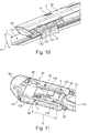
Figures 10 and 11 , a further detail of the pivotable fastening of thewiper blade 1 to thewiper arm 10 will now be discussed. In particular, it can be seen on the basis ofFigure 10 that thewiper blade 1, in particular thewiper blade body 115 thereof, is connected by way of a wiper blade adapter to thewiper arm 10 or to thecleaning arrangement 40, which, aside from thefastening arrangement 2, has anadapter element 116 which is fastened to thewiper blade body 115 and which is pivotably connected to thefastening arrangement 2 in the region of the through-opening 57 of thefastening arrangement 2. Theadapter element 116 has a length Y as viewed in the longitudinal direction of thewiper blade 1. - To make it possible for the
wiper blade 1 to be pivoted through as great as possible a pivot angle in the direction of the double arrow 117 (Figure 10 ) relative to thewiper arm 10, thewiper arm 10, in particular the cleaningarrangement 40, has twoelongated cutouts Figure 11 . The twocutouts adapter element 116. In particular, in the mounted state of thewiper blade 1 on thecleaning arrangement 40, theadapter element 116 projects into the twocutouts cutouts underside 120 of thecleaning arrangement 40 and project into theside walls cleaning arrangement 40 at the inner side thereof. In particular, provision may be made whereby, correspondingly to the illustration ofFigure 11 , the depth t of therespective cutout first spray nozzles adapter element 116. - Viewing
Figures 10 and 11 together, it can furthermore be seen that the twofeed connectors 51 of thecleaning arrangement 40 are situated approximately at the level of thecutout first spray nozzles Figure 10 shows a connectingduct 121 which connects afeed connector 51 to afirst spray nozzle duct 121 runs, in the region of thecutout cutout first spray nozzle respective feed connector 51 by way of asection 122 of curved form. - From
Figure 11 , it can also be seen that the twoside walls cleaning arrangement 40 are, on both sides of thecutouts elements 124, 125 which permit stiffening of thecleaning arrangement 40, wherein the two transverse connectingelements 124, 125 are arranged outside thefurther mount region 58 for thefastening arrangement 2 or theadapter element 116. - Below, the arrangement of a heating element in the form of a
heating wire 130, which extends within thecleaning arrangement 40, will be discussed with reference toFigures 12 to 14 . For this purpose, the cleaningarrangement 40 has amain body 131 which is connected by way of thecovering cap 95, as already described above, by way of theengagement connection 98. Theengagement connection 98 has, on thecovering cap 95, anengagement hook 132 which, in the locking position, cooperates with twocounterpart engagement elements engagement hook 132. In particular, the coveringcap 95 serves, in the installed state of thecleaning arrangement 40 on thewiper arm 10, to close off, in a surface-flush manner, thefirst mount region 21, which is open at the end side, of thewiper arm 10. - From
Figure 13 , it can be seen that the twofeed connectors 51 are connected to the respectivefirst spray nozzle duct 121. From the connectingduct 121, in the transition region to thesection 122, there extends in each case onebranch 135 with asection 137, wherein thesection 137 forms a rectilinear elongation of alongitudinal axis 136 of the connectingduct 121. In this way, thesection 122 runs at an angle α with respect to thelongitudinal axis 136. On the side averted from thebranch 135, thesection 137 has amouth region 139 which opens out within a connectingchamber 140 formed between the coveringcap 95 and themain body 131. Thesection 137 or themouth region 139 furthermore forms afeed port 141 in the connectingchamber 140. - Within the two connecting
ducts 121, between therespective feed connector 51 and thebranch 135 and within the twosections 137 and in the connectingchamber 140, the (single)heating wire 130 is led at least substantially horizontally. For this purpose, theheating wire 130 is, in the region of the connectingchamber 140, arranged in the form of aloop 142 below the twocounterpart engagement elements engagement hook 132 to interact, without making contact with theheating wire 130, with the twocounterpart engagement elements - To hydraulically seal off the
section 137 in order that no cleaning fluid can pass into the region of the connectingchamber 140, it is for example the case that a seal element 143 or a seal compound 144 is arranged within therespective mouth region 139. Furthermore, provision may be made whereby the connectingchamber 140 itself is also hydraulically sealed off to the outside by way of corresponding measures. It is also pointed out that thefeed port 141 is of tubular form, or has a hollow cross section, in the region of the connectingchamber 140. - For the mounting of the
heating wire 130 in thecleaning arrangement 40, theheating wire 130 is laid in themain body 131 corresponding to the illustration inFigure 13 . It is pointed out, merely in supplementary fashion, that theheating wire 130 is also arranged or led within the cleaninghoses cleaning arrangement 40. After the mounting of theheating wire 130 in themain body 131, it is the case, corresponding to the illustration ofFigure 14 , that the coveringcap 95 is connected by way of theengagement connection 96 to themain body 131 in order to close off the connectingchamber 140 or themain body 131. - A detail regarding the fastening or guidance of the two
cleaning hoses spray body 30, which is in the form of a moulded part, will be discussed in more detail below inFigure 15 . In particular, thespray body 30 is at least substantially formed over the entire length of the twocleaning hoses wiper arm rod 11. Thespray body 30 is connected to thewiper arm rod 11 by way of anengagement connection 150. For this purpose, thespray body 30, which has approximately a U-shaped cross section, has twogrooves sections wiper arm rod 11 engage in positively locking fashion and fix thespray body 30 to thewiper arm rod 11 in a direction running perpendicular to its longitudinal extent. - On the underside averted from the
wiper arm rod 11, thespray body 30 has in each case onemount 155 for receiving therespective cleaning hose insertion slot 156, the opening width w of which is slightly smaller than the cross section of the cleaninghose hose respective cleaning hose mount 155 by way of a clamping action. - The cleaning
hose hose mount 155 is characterized in that the cleaninghose non-circular region 158. Thenon-circular region 158 is formed by two planarouter wall sections hose mount 155 by way of a clamping action but also assumes a position with a fixed angle of rotation. For the positively locking mounting of the cleaninghose mount 155 thereof is furthermore of identical but inverse design with respect to the outer contour of the cleaninghose outer wall sections - The cleaning
hoses multiple spray nozzles 162 which are arranged so as to be spaced apart from one another in the longitudinal direction at uniform intervals and which are in the form of through-openings for forming the additional spray jets 52 (Figure 1 ). Thespray nozzles 162 are situated in the region of theinsertion slot 156. Between the twomounts 155 for the twocleaning hoses spray body 30 forms amount region 161 for the wiper blade 1 (not illustrated inFigure 15 ). In this way, by way of a corresponding supply of the cleaning fluid to the twocleaning hoses wiper blade 1 or of thewiper arm 10, for cleaning fluid to be applied to the vehicle window in each case in front of thewiper blade 1 by way of thespray nozzles 162. As already discussed above, the cleaninghoses cleaning arrangement 40, which has the first andsecond spray nozzles -
Figures 16 to 18 illustrate further details of thewiper arm 10 or of thewiper arm rod 11 which serves as carrier element, of thespray body 30 which is designed and/or acts as an auxiliary element, and of thewiper blade 1. In particular, it can be seen fromFigure 18 that thespray body 30 has two air-guidingsections wiper arm 10 or of thewiper arm rod 11 and which are arranged parallel to one another and which project beyond theunderside 168 of thewiper arm rod 11 on the side facing toward the vehicle window. In particular, fromFigure 18 , it can also be seen that the two air-guidingsections wiper arm 10 or of thewiper arm rod 11 in relation to a direction of travel, the air-guidingsection 166 projects further from theunderside 168 of thewiper arm rod 11 or of thewiper arm 10 than the air-guidingsection 167 on the rear side of thewiper arm 10. Furthermore, the two air-guidingsections underside 168 of thewiper arm carrier 11, arranged at an oblique angle γ in relation to a vertically arranged longitudinal plane of thewiper arm 10. In atransition region 171 to thewiper arm rod 11, the two-air-guidingsections wiper arm rod 11 so as to be flush with the surface of thewiper arm rod 11. - Corresponding to the illustration of
Figure 17 , thespray body 30 has a substantially U-shaped cross section with abase section 172 which connects the two air-guidingsections base section 172 has multiple cutouts or through-openings 173 which run in the longitudinal direction of thespray body 30 and which are at least approximately rectangular. The through-openings 173 are aligned with openings 174 on thewiper arm carrier 11, as can be seen in particular fromFigure 16 , wherein the openings 174 are of at least approximately the same size as the through-openings 173. - Finally,
Figures 19 to 22 illustrate the guidance and fastening of the twocleaning hoses wiper arm head 14 in more detail. In particular, it can be seen that thewiper arm head 14 has, in the region between thefirst end region 178, in which the through-opening 15 for the drive shaft is arranged, and thesecond end region 179, in which thewiper arm rod 11 is pivotably fastened, means for guiding the twocleaning hoses hose outer contour 185 of thewiper arm head 14, anopening 186 through which therespective cleaning hose hose top side 187 of thewiper arm head 14 on the side facing toward thefirst end region 178, said cleaning hose is arranged above theunderside 188 of thewiper arm head 14 on the side facing toward thesecond end region 179. - From
Figures 19 and 22 , it can also be seen that the means for guiding the twocleaning hoses guide projections 190. Theguide projections 190 are integrally formed on thewiper arm head 14, which is composed of aluminium (alternatively plastic) and which is in the form of an injection-moulded part, and have the effect that the twocleaning hoses outer contour 185 of thewiper arm head 14, in particular in order to also permit simple fastening of thecovering cap 16 on thewiper arm head 14. The coveringcap 16, which has substantially a U-shaped cross section, hasside walls side surfaces wiper arm head 14. - Furthermore, it can be seen in particular from
Figure 21 that the twoleadthroughs longitudinal axis 191 of thewiper arm head 14. - The
second end region 179 has aneyelet 197 for forming apivot axis 198. Furthermore, the means for guiding thecleaning hoses projections eyelet 197 on the side situated opposite thefirst end region 178. Between the twoprojections bridging spring 203 which is bent into a C shape and which in turn is connected, on the side averted from thesecond end region 179, to atension spring 205 by way of which thewiper arm rod 11 is pulled together with thewiper blade 1 in the direction of the vehicle window with a pressing force. Thewiper arm head 14 has, below theeyelet 197, a guide channel 206 for the cleaninghose hose eyelet 197. It is finally pointed out that the twoleadthroughs outer contour 185 of thewiper arm head 14. - The
wiper device 100 thus described may be altered or modified in a variety of ways. -
- 1
- Wiper blade
- 2
- Fastening arrangement
- 3
- Spring tongue
- 4
- Engagement button
- 5
- Opening
- 10/a/b/c/d
- Wiper arm
- 11
- Wiper arm rod
- 12
- Pin
- 13
- Sleeve
- 14
- Wiper arm head
- 15
- Through-opening
- 16
- Covering cap
- 17
- Wiper arm axis
- 18
- Top side of the wiper arm rod
- 19
- Side wall of the wiper arm rod
- 20
- Side wall of the wiper arm rod
- 21
- First mount region
- 22
- Second mount region
- 30
- Spray body
- 31
- Cleaning hose
- 32
- Cleaning hose
- 40/a/b/c/d
- Cleaning arrangement
- 41/a
- Front end face
- 42
- First spray nozzle
- 43
- First spray nozzle
- 45
- Spray jet
- 46
- Spray jet
- 47
- Second spray nozzle
- 48
- Second spray nozzle
- 49
- Spray jet
- 50
- Spray jet
- 51
- Feed connector
- 52
- Additional spray jet
- 53
- Wiping direction
- 54/a/b/c/d
- Side wall
- 55/a/b/c/d
- Side wall
- 57
- Through-opening
- 58
- Additional mount region
- 59
- Lug
- 60
- Lug
- 61/a
- First mounting direction
- 62/a
- Second mounting direction
- 65
- First guide means
- 66
- Second guide means
- 67
- Side wall
- 68
- Side wall
- 71
- First elevation
- 72
- Second elevation
- 73
- Bottom edge of the cleaning arrangement
- 74
- Top edge of the cleaning arrangement
- 75
- Depression
- 76
- Depression
- 77
- Movement play
- 78
- Elongate depression
- 80
- Starting position
- 81
- End position
- 82
- Opening
- 83
- Axis of rotation
- 84
- Delimiting surface of the depression
- 85
- Delimiting surface of the depression
- 87
- Engagement cam
- 88
- Bayonet connection
- 89
- Projection
- 90
- Projection
- 91
- Cutout
- 92
- Cutout
- 93
- End side
- 94
- Rear side of a covering cap
- 95
- Covering cap
- 96
- Engagement connection
- 97
- End face
- 98
- Engagement connection
- 99
- Engagement cam
- 100
- Wiper device
- 101
- Mounting direction
- 102
- Engagement connection
- 103
- Barb
- 105
- Positively locking connection
- 106
- Guide element
- 107
- Guide element
- 108
- Cutouts
- 109
- Mounting direction
- 110
- Engagement hook
- 115
- Wiper blade body
- 116
- Adapter element
- 117
- Double arrow
- 118
- Cutout
- 119
- Cutout
- 120
- Bottom side of the cleaning arrangement
- 121
- Connecting duct
- 122
- Curved section
- 124
- Transverse connecting element
- 125
- Transverse connecting element
- 130
- Heating wire
- 131
- Main body
- 132
- Engagement hook
- 133
- Counterpart engagement element
- 134
- Counterpart engagement element
- 135
- Branch
- 136
- Longitudinal axis
- 137
- Section
- 139
- Mouth region
- 140
- Connecting chamber
- 141
- Feed port
- 142
- Loop
- 143
- Seal element
- 144
- Seal compound
- 150
- Engagement connection
- 151
- Groove
- 152
- Groove
- 153
- Section
- 154
- Section
- 155
- Mount
- 156
- Insertion slot
- 158
- Non-circular region
- 159
- Outer wall section
- 160
- Outer wall section
- 161
- Mount region
- 162
- Spray nozzle
- 166
- Air-guiding section
- 167
- Air-guiding section
- 168
- Underside of the wiper arm carrier
- 171
- Transition region
- 172
- Base section
- 173
- Through-openings
- 174
- Opening
- 178
- First end region
- 179
- Second end region
- 181
- Leadthrough
- 182
- Leadthrough
- 185
- Outer contour of the wiper arm head
- 186
- Opening
- 187
- Top side of the wiper arm head
- 188
- Bottom side of the wiper arm head
- 190
- Guide projection
- 191
- Longitudinal axis of the wiper arm head
- 192
- Side wall of the covering cap
- 193
- Side wall of the covering cap
- 194
- Side surface of the wiper arm head
- 195
- Side surface of the wiper arm head
- 197
- Eyelet
- 198
- Pivot axis
- 201
- Projection
- 202
- Projection
- 203
- Bridging spring
- 205
- Tension spring
- 206
- Guide channel
- A
- Spacing
- B
- Width of the depressions
- b
- Width
- L
- Length
- l
- Length
- t
- Depth
- w
- Opening width
- Y
- Length
- X
- Length
- α
- Angle
- β
- Angle
- γ
- Angle
Claims (12)
- A wiper arm head (14) for a wiper arm rod (11), with a first end region (178), which has an opening (15) for receiving a drive shaft, and a second end region (179) for the pivotable fastening of the wiper arm rod (11), and with means for directing at least one hose (31, 32) carrying a cleaning fluid,
characterized in that
the means has a feedthrough (181, 182), which leads the hose (31, 32) from an upper side (187) in the direction of an underside (188) of the wiper arm head (14). - The wiper arm head according to Claim 1,
characterized in that
the feedthrough (181, 182) is constructed in the form of a longitudinal slot. - The wiper arm head according to Claim 2,
characterized in that
the feedthrough (181, 182), viewed towards the outer contour (185) of the wiper arm head (14), has an opening (186) through which the hose (31, 32) is able to be introduced in the direction of the feedthrough (181, 182). - The wiper arm head according to one of Claims 1 to 3,
characterized in that
the hose (31, 32) is arranged on the side facing the first end region (178) along the upper side (187) of the wiper arm head (14) and on the side facing the second end region (179) above the underside (188) of the wiper arm head (140). - The wiper arm head according to one of Claims 1 to 4,
characterized in that
the means additionally have at least one guide projection (190). - The wiper arm head according to one of Claims 1 to 5,
characterized in that
two feedthroughs (181, 182) are provided on opposite sides of the wiper arm head (14), and that the two feedthroughs (181, 182) are arranged offset to one another in relation to a longitudinal axis (191) of the wiper arm head (14). - The wiper arm head according to one of Claims 1 to 6,
characterized in that
the wiper arm head (14) is constructed out of aluminium as an injection moulded part. - The wiper arm head according to one of Claims 1 to 7,
characterized in that
the wiper arm head (14) is covered by a covering cap (16), which is constructed at least substantially in a U-shape in cross-section, and the side walls (192, 193) of which terminate flush with side faces (194, 195) of the wiper arm head (14). - The wiper arm head according to one of Claims 1 to 8,
characterized in that
the second end region (179) has an eye (197) for the formation of a pivot axis (198) for the wiper arm rod (11), and that the means have at least one extension (201, 202) which, viewed in longitudinal direction, projects beyond the eye (197) on the side lying opposite the first end region (178). - The wiper arm head according to Claim 9,
characterized in that
the wiper arm head (14) has a guide channel (206) for the hose (31, 32) beneath the eye (197), which guide channel (206) directs the hose (31, 32) spaced apart with respect to the eye (197). - The wiper arm head according to one of Claims 1 to 10,
characterized in that
the feedthrough (181, 182) is arranged within the outer contour (185) of the wiper arm head (14). - A wiper arm (10; 10a - 10d) for vehicle windows, with a wiper arm head (14) which is constructed according to one of Claims 1 to 11, a wiper arm rod (11) and at least one hose (31, 32) for a cleaning fluid, directed within the wiper arm head (14) and the wiper arm rod (11).
Applications Claiming Priority (1)
| Application Number | Priority Date | Filing Date | Title |
|---|---|---|---|
| DE102015114933.8A DE102015114933A1 (en) | 2015-09-07 | 2015-09-07 | Wiper arm head for a wiper arm and wiper arm for vehicle windows |
Publications (3)
| Publication Number | Publication Date |
|---|---|
| EP3138742A2 true EP3138742A2 (en) | 2017-03-08 |
| EP3138742A3 EP3138742A3 (en) | 2017-03-15 |
| EP3138742B1 EP3138742B1 (en) | 2019-07-24 |
Family
ID=56802377
Family Applications (1)
| Application Number | Title | Priority Date | Filing Date |
|---|---|---|---|
| EP16185949.1A Active EP3138742B1 (en) | 2015-09-07 | 2016-08-26 | Wiper arm head for a wiper arm rod and wiper arm for vehicle windows |
Country Status (4)
| Country | Link |
|---|---|
| US (1) | US10583810B2 (en) |
| EP (1) | EP3138742B1 (en) |
| CN (1) | CN106494359B (en) |
| DE (1) | DE102015114933A1 (en) |
Families Citing this family (5)
| Publication number | Priority date | Publication date | Assignee | Title |
|---|---|---|---|---|
| CN107719313A (en) * | 2017-09-15 | 2018-02-23 | 合肥清雅装饰工程有限公司 | A kind of car-mounted car washer |
| DE102017219908A1 (en) * | 2017-11-09 | 2019-05-09 | Robert Bosch Gmbh | wiper arm |
| DE102019123945A1 (en) * | 2019-09-06 | 2021-03-11 | Valeo Wischersysteme Gmbh | Cover profile for a wiper arm of a wiper system and method for assembling a wiper arm |
| DE102021203776A1 (en) | 2021-04-16 | 2022-10-20 | Volkswagen Aktiengesellschaft | Spray device for a wiper device |
| DE102021214184A1 (en) | 2021-12-13 | 2023-06-15 | Robert Bosch Gesellschaft mit beschränkter Haftung | Wiper arm, in particular for a motor vehicle |
Family Cites Families (14)
| Publication number | Priority date | Publication date | Assignee | Title |
|---|---|---|---|---|
| US3427675A (en) * | 1967-07-03 | 1969-02-18 | James W Tibbet | Windshield wiper and washer assembly |
| CH462642A (en) * | 1967-08-18 | 1968-09-15 | Neuer Arthur | windshield wipers |
| DE3824483A1 (en) * | 1988-07-20 | 1990-01-25 | Bosch Gmbh Robert | WIPING DEVICE FOR WINDOWS OF MOTOR VEHICLES |
| DE4134980B4 (en) * | 1991-10-23 | 2005-12-22 | Itt Automotive Europe Gmbh | Wiper device for windows of motor vehicles |
| FR2684343A1 (en) * | 1991-11-29 | 1993-06-04 | Peugeot | Device for spraying washer fluid incorporated into a windscreen wiper, particularly for a motor vehicle |
| JP2605107Y2 (en) * | 1992-01-22 | 2000-06-26 | 株式会社ミツバ | Arrangement structure of washer hose in wiper arm |
| DE19716248A1 (en) * | 1996-07-04 | 1998-01-08 | Itt Mfg Enterprises Inc | Wet wiper arm of a windshield wiper device for windows of vehicles |
| US6804854B2 (en) * | 2001-03-23 | 2004-10-19 | Asmo Co., Ltd. | Windshield wiper device mounting washer nozzle and hose |
| JP5653729B2 (en) * | 2010-11-18 | 2015-01-14 | 株式会社ミツバ | Vehicle wiper device |
| DE102012107232A1 (en) * | 2012-08-07 | 2014-05-15 | Valeo Systèmes d'Essuyage | Wiper device and wiper arm for cleaning a vehicle window |
| FR2999130B1 (en) * | 2012-12-10 | 2017-05-05 | Valeo Systemes Dessuyage | TRAINER, DEVICE FOR MAINTAINING A PIPE, IN PARTICULAR A WASHER LIQUID, AND A CORRESPONDING WIPING SYSTEM |
| DE102013209959A1 (en) * | 2013-05-28 | 2014-12-04 | Robert Bosch Gmbh | Wischarmvorrichtung |
| DE102014201211A1 (en) * | 2014-01-23 | 2015-07-23 | Robert Bosch Gmbh | wiper device |
| DE102014226351A1 (en) * | 2014-12-18 | 2016-06-23 | Robert Bosch Gmbh | Wischarmvorrichtung |
-
2015
- 2015-09-07 DE DE102015114933.8A patent/DE102015114933A1/en not_active Withdrawn
-
2016
- 2016-08-26 EP EP16185949.1A patent/EP3138742B1/en active Active
- 2016-09-07 CN CN201610808526.1A patent/CN106494359B/en active Active
- 2016-09-07 US US15/258,321 patent/US10583810B2/en not_active Expired - Fee Related
Non-Patent Citations (1)
| Title |
|---|
| None |
Also Published As
| Publication number | Publication date |
|---|---|
| EP3138742A3 (en) | 2017-03-15 |
| US20170066409A1 (en) | 2017-03-09 |
| DE102015114933A1 (en) | 2017-03-09 |
| EP3138742B1 (en) | 2019-07-24 |
| US10583810B2 (en) | 2020-03-10 |
| CN106494359B (en) | 2020-07-28 |
| CN106494359A (en) | 2017-03-15 |
Similar Documents
| Publication | Publication Date | Title |
|---|---|---|
| EP3138746B1 (en) | Cleaning arrangement for the cleaning of vehicle windows, and wiper device | |
| EP3138742B1 (en) | Wiper arm head for a wiper arm rod and wiper arm for vehicle windows | |
| EP3138744B1 (en) | Wiper device for vehicle windows | |
| EP3138743B1 (en) | Wiper device for cleaning vehicle windows | |
| JP5480270B2 (en) | Wiper arm / wiper blade connecting device and wiper blade | |
| US10343652B2 (en) | Wiper device for cleaning vehicle windows, and cleaning arrangement for a wiper device | |
| US20160101763A1 (en) | Wiper arm for a windscreen wiper system of a motor vehicle, wiper blade and wiper device | |
| EP3138741B1 (en) | Wiper arm for cleaning a vehicle window | |
| EP3138740B1 (en) | Cleaning arrangement for cleaning a vehicle window | |
| EP3138745B1 (en) | Wiper device for cleaning vehicle windows | |
| JP6313655B2 (en) | Wiper arm with nozzle and wiper device for vehicle |
Legal Events
| Date | Code | Title | Description |
|---|---|---|---|
| PUAI | Public reference made under article 153(3) epc to a published international application that has entered the european phase |
Free format text: ORIGINAL CODE: 0009012 |
|
| STAA | Information on the status of an ep patent application or granted ep patent |
Free format text: STATUS: REQUEST FOR EXAMINATION WAS MADE |
|
| PUAL | Search report despatched |
Free format text: ORIGINAL CODE: 0009013 |
|
| 17P | Request for examination filed |
Effective date: 20160826 |
|
| AK | Designated contracting states |
Kind code of ref document: A2 Designated state(s): AL AT BE BG CH CY CZ DE DK EE ES FI FR GB GR HR HU IE IS IT LI LT LU LV MC MK MT NL NO PL PT RO RS SE SI SK SM TR |
|
| AX | Request for extension of the european patent |
Extension state: BA ME |
|
| AK | Designated contracting states |
Kind code of ref document: A3 Designated state(s): AL AT BE BG CH CY CZ DE DK EE ES FI FR GB GR HR HU IE IS IT LI LT LU LV MC MK MT NL NO PL PT RO RS SE SI SK SM TR |
|
| AX | Request for extension of the european patent |
Extension state: BA ME |
|
| RIC1 | Information provided on ipc code assigned before grant |
Ipc: B60S 1/34 20060101AFI20170206BHEP Ipc: B60S 1/52 20060101ALI20170206BHEP |
|
| STAA | Information on the status of an ep patent application or granted ep patent |
Free format text: STATUS: EXAMINATION IS IN PROGRESS |
|
| 17Q | First examination report despatched |
Effective date: 20180531 |
|
| GRAP | Despatch of communication of intention to grant a patent |
Free format text: ORIGINAL CODE: EPIDOSNIGR1 |
|
| STAA | Information on the status of an ep patent application or granted ep patent |
Free format text: STATUS: GRANT OF PATENT IS INTENDED |
|
| INTG | Intention to grant announced |
Effective date: 20190218 |
|
| GRAS | Grant fee paid |
Free format text: ORIGINAL CODE: EPIDOSNIGR3 |
|
| GRAA | (expected) grant |
Free format text: ORIGINAL CODE: 0009210 |
|
| STAA | Information on the status of an ep patent application or granted ep patent |
Free format text: STATUS: THE PATENT HAS BEEN GRANTED |
|
| AK | Designated contracting states |
Kind code of ref document: B1 Designated state(s): AL AT BE BG CH CY CZ DE DK EE ES FI FR GB GR HR HU IE IS IT LI LT LU LV MC MK MT NL NO PL PT RO RS SE SI SK SM TR |
|
| REG | Reference to a national code |
Ref country code: GB Ref legal event code: FG4D |
|
| REG | Reference to a national code |
Ref country code: CH Ref legal event code: EP |
|
| REG | Reference to a national code |
Ref country code: DE Ref legal event code: R096 Ref document number: 602016017218 Country of ref document: DE |
|
| REG | Reference to a national code |
Ref country code: AT Ref legal event code: REF Ref document number: 1157796 Country of ref document: AT Kind code of ref document: T Effective date: 20190815 |
|
| REG | Reference to a national code |
Ref country code: IE Ref legal event code: FG4D |
|
| REG | Reference to a national code |
Ref country code: NL Ref legal event code: MP Effective date: 20190724 |
|
| REG | Reference to a national code |
Ref country code: LT Ref legal event code: MG4D |
|
| REG | Reference to a national code |
Ref country code: AT Ref legal event code: MK05 Ref document number: 1157796 Country of ref document: AT Kind code of ref document: T Effective date: 20190724 |
|
| PG25 | Lapsed in a contracting state [announced via postgrant information from national office to epo] |
Ref country code: NO Free format text: LAPSE BECAUSE OF FAILURE TO SUBMIT A TRANSLATION OF THE DESCRIPTION OR TO PAY THE FEE WITHIN THE PRESCRIBED TIME-LIMIT Effective date: 20191024 Ref country code: AT Free format text: LAPSE BECAUSE OF FAILURE TO SUBMIT A TRANSLATION OF THE DESCRIPTION OR TO PAY THE FEE WITHIN THE PRESCRIBED TIME-LIMIT Effective date: 20190724 Ref country code: FI Free format text: LAPSE BECAUSE OF FAILURE TO SUBMIT A TRANSLATION OF THE DESCRIPTION OR TO PAY THE FEE WITHIN THE PRESCRIBED TIME-LIMIT Effective date: 20190724 Ref country code: LT Free format text: LAPSE BECAUSE OF FAILURE TO SUBMIT A TRANSLATION OF THE DESCRIPTION OR TO PAY THE FEE WITHIN THE PRESCRIBED TIME-LIMIT Effective date: 20190724 Ref country code: HR Free format text: LAPSE BECAUSE OF FAILURE TO SUBMIT A TRANSLATION OF THE DESCRIPTION OR TO PAY THE FEE WITHIN THE PRESCRIBED TIME-LIMIT Effective date: 20190724 Ref country code: PT Free format text: LAPSE BECAUSE OF FAILURE TO SUBMIT A TRANSLATION OF THE DESCRIPTION OR TO PAY THE FEE WITHIN THE PRESCRIBED TIME-LIMIT Effective date: 20191125 Ref country code: NL Free format text: LAPSE BECAUSE OF FAILURE TO SUBMIT A TRANSLATION OF THE DESCRIPTION OR TO PAY THE FEE WITHIN THE PRESCRIBED TIME-LIMIT Effective date: 20190724 Ref country code: SE Free format text: LAPSE BECAUSE OF FAILURE TO SUBMIT A TRANSLATION OF THE DESCRIPTION OR TO PAY THE FEE WITHIN THE PRESCRIBED TIME-LIMIT Effective date: 20190724 Ref country code: BG Free format text: LAPSE BECAUSE OF FAILURE TO SUBMIT A TRANSLATION OF THE DESCRIPTION OR TO PAY THE FEE WITHIN THE PRESCRIBED TIME-LIMIT Effective date: 20191024 |
|
| PG25 | Lapsed in a contracting state [announced via postgrant information from national office to epo] |
Ref country code: GR Free format text: LAPSE BECAUSE OF FAILURE TO SUBMIT A TRANSLATION OF THE DESCRIPTION OR TO PAY THE FEE WITHIN THE PRESCRIBED TIME-LIMIT Effective date: 20191025 Ref country code: LV Free format text: LAPSE BECAUSE OF FAILURE TO SUBMIT A TRANSLATION OF THE DESCRIPTION OR TO PAY THE FEE WITHIN THE PRESCRIBED TIME-LIMIT Effective date: 20190724 Ref country code: AL Free format text: LAPSE BECAUSE OF FAILURE TO SUBMIT A TRANSLATION OF THE DESCRIPTION OR TO PAY THE FEE WITHIN THE PRESCRIBED TIME-LIMIT Effective date: 20190724 Ref country code: RS Free format text: LAPSE BECAUSE OF FAILURE TO SUBMIT A TRANSLATION OF THE DESCRIPTION OR TO PAY THE FEE WITHIN THE PRESCRIBED TIME-LIMIT Effective date: 20190724 Ref country code: IS Free format text: LAPSE BECAUSE OF FAILURE TO SUBMIT A TRANSLATION OF THE DESCRIPTION OR TO PAY THE FEE WITHIN THE PRESCRIBED TIME-LIMIT Effective date: 20191124 Ref country code: ES Free format text: LAPSE BECAUSE OF FAILURE TO SUBMIT A TRANSLATION OF THE DESCRIPTION OR TO PAY THE FEE WITHIN THE PRESCRIBED TIME-LIMIT Effective date: 20190724 |
|
| PG25 | Lapsed in a contracting state [announced via postgrant information from national office to epo] |
Ref country code: TR Free format text: LAPSE BECAUSE OF FAILURE TO SUBMIT A TRANSLATION OF THE DESCRIPTION OR TO PAY THE FEE WITHIN THE PRESCRIBED TIME-LIMIT Effective date: 20190724 |
|
| PG25 | Lapsed in a contracting state [announced via postgrant information from national office to epo] |
Ref country code: RO Free format text: LAPSE BECAUSE OF FAILURE TO SUBMIT A TRANSLATION OF THE DESCRIPTION OR TO PAY THE FEE WITHIN THE PRESCRIBED TIME-LIMIT Effective date: 20190724 Ref country code: IT Free format text: LAPSE BECAUSE OF FAILURE TO SUBMIT A TRANSLATION OF THE DESCRIPTION OR TO PAY THE FEE WITHIN THE PRESCRIBED TIME-LIMIT Effective date: 20190724 Ref country code: DK Free format text: LAPSE BECAUSE OF FAILURE TO SUBMIT A TRANSLATION OF THE DESCRIPTION OR TO PAY THE FEE WITHIN THE PRESCRIBED TIME-LIMIT Effective date: 20190724 Ref country code: PL Free format text: LAPSE BECAUSE OF FAILURE TO SUBMIT A TRANSLATION OF THE DESCRIPTION OR TO PAY THE FEE WITHIN THE PRESCRIBED TIME-LIMIT Effective date: 20190724 Ref country code: EE Free format text: LAPSE BECAUSE OF FAILURE TO SUBMIT A TRANSLATION OF THE DESCRIPTION OR TO PAY THE FEE WITHIN THE PRESCRIBED TIME-LIMIT Effective date: 20190724 |
|
| PG25 | Lapsed in a contracting state [announced via postgrant information from national office to epo] |
Ref country code: LI Free format text: LAPSE BECAUSE OF NON-PAYMENT OF DUE FEES Effective date: 20190831 Ref country code: CZ Free format text: LAPSE BECAUSE OF FAILURE TO SUBMIT A TRANSLATION OF THE DESCRIPTION OR TO PAY THE FEE WITHIN THE PRESCRIBED TIME-LIMIT Effective date: 20190724 Ref country code: LU Free format text: LAPSE BECAUSE OF NON-PAYMENT OF DUE FEES Effective date: 20190826 Ref country code: SM Free format text: LAPSE BECAUSE OF FAILURE TO SUBMIT A TRANSLATION OF THE DESCRIPTION OR TO PAY THE FEE WITHIN THE PRESCRIBED TIME-LIMIT Effective date: 20190724 Ref country code: CH Free format text: LAPSE BECAUSE OF NON-PAYMENT OF DUE FEES Effective date: 20190831 Ref country code: SK Free format text: LAPSE BECAUSE OF FAILURE TO SUBMIT A TRANSLATION OF THE DESCRIPTION OR TO PAY THE FEE WITHIN THE PRESCRIBED TIME-LIMIT Effective date: 20190724 Ref country code: MC Free format text: LAPSE BECAUSE OF FAILURE TO SUBMIT A TRANSLATION OF THE DESCRIPTION OR TO PAY THE FEE WITHIN THE PRESCRIBED TIME-LIMIT Effective date: 20190724 Ref country code: IS Free format text: LAPSE BECAUSE OF FAILURE TO SUBMIT A TRANSLATION OF THE DESCRIPTION OR TO PAY THE FEE WITHIN THE PRESCRIBED TIME-LIMIT Effective date: 20200224 |
|
| REG | Reference to a national code |
Ref country code: DE Ref legal event code: R097 Ref document number: 602016017218 Country of ref document: DE |
|
| PLBE | No opposition filed within time limit |
Free format text: ORIGINAL CODE: 0009261 |
|
| STAA | Information on the status of an ep patent application or granted ep patent |
Free format text: STATUS: NO OPPOSITION FILED WITHIN TIME LIMIT |
|
| PG2D | Information on lapse in contracting state deleted |
Ref country code: IS |
|
| PG25 | Lapsed in a contracting state [announced via postgrant information from national office to epo] |
Ref country code: IE Free format text: LAPSE BECAUSE OF NON-PAYMENT OF DUE FEES Effective date: 20190826 |
|
| 26N | No opposition filed |
Effective date: 20200603 |
|
| PG25 | Lapsed in a contracting state [announced via postgrant information from national office to epo] |
Ref country code: SI Free format text: LAPSE BECAUSE OF FAILURE TO SUBMIT A TRANSLATION OF THE DESCRIPTION OR TO PAY THE FEE WITHIN THE PRESCRIBED TIME-LIMIT Effective date: 20190724 |
|
| GBPC | Gb: european patent ceased through non-payment of renewal fee |
Effective date: 20200826 |
|
| PG25 | Lapsed in a contracting state [announced via postgrant information from national office to epo] |
Ref country code: CY Free format text: LAPSE BECAUSE OF FAILURE TO SUBMIT A TRANSLATION OF THE DESCRIPTION OR TO PAY THE FEE WITHIN THE PRESCRIBED TIME-LIMIT Effective date: 20190724 |
|
| PG25 | Lapsed in a contracting state [announced via postgrant information from national office to epo] |
Ref country code: HU Free format text: LAPSE BECAUSE OF FAILURE TO SUBMIT A TRANSLATION OF THE DESCRIPTION OR TO PAY THE FEE WITHIN THE PRESCRIBED TIME-LIMIT; INVALID AB INITIO Effective date: 20160826 Ref country code: MT Free format text: LAPSE BECAUSE OF FAILURE TO SUBMIT A TRANSLATION OF THE DESCRIPTION OR TO PAY THE FEE WITHIN THE PRESCRIBED TIME-LIMIT Effective date: 20190724 |
|
| PG25 | Lapsed in a contracting state [announced via postgrant information from national office to epo] |
Ref country code: GB Free format text: LAPSE BECAUSE OF NON-PAYMENT OF DUE FEES Effective date: 20200826 |
|
| PG25 | Lapsed in a contracting state [announced via postgrant information from national office to epo] |
Ref country code: MK Free format text: LAPSE BECAUSE OF FAILURE TO SUBMIT A TRANSLATION OF THE DESCRIPTION OR TO PAY THE FEE WITHIN THE PRESCRIBED TIME-LIMIT Effective date: 20190724 |
|
| P01 | Opt-out of the competence of the unified patent court (upc) registered |
Effective date: 20230528 |
|
| PGFP | Annual fee paid to national office [announced via postgrant information from national office to epo] |
Ref country code: FR Payment date: 20230828 Year of fee payment: 8 Ref country code: DE Payment date: 20230808 Year of fee payment: 8 Ref country code: BE Payment date: 20230822 Year of fee payment: 8 |