EP3138670A1 - Industrial robot - Google Patents
Industrial robot Download PDFInfo
- Publication number
- EP3138670A1 EP3138670A1 EP15786446.3A EP15786446A EP3138670A1 EP 3138670 A1 EP3138670 A1 EP 3138670A1 EP 15786446 A EP15786446 A EP 15786446A EP 3138670 A1 EP3138670 A1 EP 3138670A1
- Authority
- EP
- European Patent Office
- Prior art keywords
- arm
- lower arm
- industrial robot
- side part
- parallel link
- Prior art date
- Legal status (The legal status is an assumption and is not a legal conclusion. Google has not performed a legal analysis and makes no representation as to the accuracy of the status listed.)
- Granted
Links
Images


Classifications
-
- B—PERFORMING OPERATIONS; TRANSPORTING
- B25—HAND TOOLS; PORTABLE POWER-DRIVEN TOOLS; MANIPULATORS
- B25J—MANIPULATORS; CHAMBERS PROVIDED WITH MANIPULATION DEVICES
- B25J9/00—Program-controlled manipulators
- B25J9/10—Program-controlled manipulators characterised by positioning means for manipulator elements
- B25J9/106—Program-controlled manipulators characterised by positioning means for manipulator elements with articulated links
- B25J9/1065—Program-controlled manipulators characterised by positioning means for manipulator elements with articulated links with parallelograms
-
- B—PERFORMING OPERATIONS; TRANSPORTING
- B25—HAND TOOLS; PORTABLE POWER-DRIVEN TOOLS; MANIPULATORS
- B25J—MANIPULATORS; CHAMBERS PROVIDED WITH MANIPULATION DEVICES
- B25J9/00—Program-controlled manipulators
- B25J9/06—Program-controlled manipulators characterised by multi-articulated arms
-
- B—PERFORMING OPERATIONS; TRANSPORTING
- B25—HAND TOOLS; PORTABLE POWER-DRIVEN TOOLS; MANIPULATORS
- B25J—MANIPULATORS; CHAMBERS PROVIDED WITH MANIPULATION DEVICES
- B25J9/00—Program-controlled manipulators
- B25J9/10—Program-controlled manipulators characterised by positioning means for manipulator elements
- B25J9/106—Program-controlled manipulators characterised by positioning means for manipulator elements with articulated links
-
- B—PERFORMING OPERATIONS; TRANSPORTING
- B25—HAND TOOLS; PORTABLE POWER-DRIVEN TOOLS; MANIPULATORS
- B25J—MANIPULATORS; CHAMBERS PROVIDED WITH MANIPULATION DEVICES
- B25J18/00—Arms
-
- B—PERFORMING OPERATIONS; TRANSPORTING
- B25—HAND TOOLS; PORTABLE POWER-DRIVEN TOOLS; MANIPULATORS
- B25J—MANIPULATORS; CHAMBERS PROVIDED WITH MANIPULATION DEVICES
- B25J19/00—Accessories fitted to manipulators, e.g. for monitoring, for viewing; Safety devices combined with or specially adapted for use in connection with manipulators
- B25J19/0008—Balancing devices
- B25J19/0012—Balancing devices using fluidic devices
-
- B—PERFORMING OPERATIONS; TRANSPORTING
- B25—HAND TOOLS; PORTABLE POWER-DRIVEN TOOLS; MANIPULATORS
- B25J—MANIPULATORS; CHAMBERS PROVIDED WITH MANIPULATION DEVICES
- B25J19/00—Accessories fitted to manipulators, e.g. for monitoring, for viewing; Safety devices combined with or specially adapted for use in connection with manipulators
- B25J19/0008—Balancing devices
- B25J19/0016—Balancing devices using springs
-
- B—PERFORMING OPERATIONS; TRANSPORTING
- B25—HAND TOOLS; PORTABLE POWER-DRIVEN TOOLS; MANIPULATORS
- B25J—MANIPULATORS; CHAMBERS PROVIDED WITH MANIPULATION DEVICES
- B25J19/00—Accessories fitted to manipulators, e.g. for monitoring, for viewing; Safety devices combined with or specially adapted for use in connection with manipulators
- B25J19/0075—Means for protecting the manipulator from its environment or vice versa
-
- B—PERFORMING OPERATIONS; TRANSPORTING
- B25—HAND TOOLS; PORTABLE POWER-DRIVEN TOOLS; MANIPULATORS
- B25J—MANIPULATORS; CHAMBERS PROVIDED WITH MANIPULATION DEVICES
- B25J19/00—Accessories fitted to manipulators, e.g. for monitoring, for viewing; Safety devices combined with or specially adapted for use in connection with manipulators
- B25J19/0091—Shock absorbers
-
- B—PERFORMING OPERATIONS; TRANSPORTING
- B25—HAND TOOLS; PORTABLE POWER-DRIVEN TOOLS; MANIPULATORS
- B25J—MANIPULATORS; CHAMBERS PROVIDED WITH MANIPULATION DEVICES
- B25J9/00—Program-controlled manipulators
- B25J9/02—Program-controlled manipulators characterised by movement of the arms, e.g. cartesian coordinate type
- B25J9/04—Program-controlled manipulators characterised by movement of the arms, e.g. cartesian coordinate type by rotating at least one arm, excluding the head movement itself, e.g. cylindrical coordinate type or polar coordinate type
- B25J9/041—Cylindrical coordinate type
- B25J9/042—Cylindrical coordinate type comprising an articulated arm
-
- B—PERFORMING OPERATIONS; TRANSPORTING
- B25—HAND TOOLS; PORTABLE POWER-DRIVEN TOOLS; MANIPULATORS
- B25J—MANIPULATORS; CHAMBERS PROVIDED WITH MANIPULATION DEVICES
- B25J9/00—Program-controlled manipulators
- B25J9/16—Program controls
- B25J9/1679—Program controls characterised by the tasks executed
- B25J9/1687—Assembly, peg and hole, palletising, straight line, weaving pattern movement
-
- Y—GENERAL TAGGING OF NEW TECHNOLOGICAL DEVELOPMENTS; GENERAL TAGGING OF CROSS-SECTIONAL TECHNOLOGIES SPANNING OVER SEVERAL SECTIONS OF THE IPC; TECHNICAL SUBJECTS COVERED BY FORMER USPC CROSS-REFERENCE ART COLLECTIONS [XRACs] AND DIGESTS
- Y10—TECHNICAL SUBJECTS COVERED BY FORMER USPC
- Y10S—TECHNICAL SUBJECTS COVERED BY FORMER USPC CROSS-REFERENCE ART COLLECTIONS [XRACs] AND DIGESTS
- Y10S901/00—Robots
- Y10S901/48—Counterbalance
Definitions
- the present invention relates to an industrial robot, and more particularly, to an industrial robot comprising an arm mechanism having a parallel link structure.
- industrial robots are installed in various factories for producing electric apparatus, machines, auto mobiles, and the like as a conveyance robot for conveying objects and a working robot for machining objects.
- the industrial robots include various types according to the use, and one of them is a robot comprising an arm mechanism having a parallel link structure (Patent Literature 1).
- This type of robot comprises a lower arm mechanism having the parallel link structure, and an upper arm mechanism is connected to the lower arm mechanism.
- This robot has a feature that its lower arm mechanism has the parallel link structure, and therefore the posture of the upper arm mechanism does not change even when the lower arm configuring the lower arm mechanism performs an inclining operation.
- this type of robot is suitable for an operation that objects are held by an end effector which is mounted to a wrist portion and piled up on a pallet (palletizing operation).
- Such palletizing robots include one that not only the lower arm mechanism but also the upper arm mechanism has the parallel link structure (Patent Literature 2).
- An object of the present invention is to provide an industrial robot capable of expanding the range of the portable mass of an object without enlarging an arm drive motor and declining an arm operation speed.
- an industrial robot comprises a lower arm mechanism having a first parallel link structure, an upper arm mechanism having a second parallel link structure, a base portion forming a lower side part of the first parallel link structure, a wrist portion forming a distal side part of the second parallel link structure, an intermediate connection portion forming an upper side part of the first parallel link structure and a proximal side part of the second parallel link structure, and an upper arm biasing unit configured to apply a biasing force against a rotating operation in a direction that the wrist portion descends to an upper arm configuring a lower side part or an upper side part of the second parallel link structure.
- the present invention according to a second aspect is that, in the present invention according to the first aspect, the upper arm has an arm extension portion extending exceeding a rotational axis of the upper arm on a proximal end side of the upper arm, and the upper arm biasing unit is configured so as to apply a biasing force to the arm extension portion.
- the present invention according to a third aspect is that, in the present invention according to the second aspect, the biasing force of the upper arm biasing unit works in a direction that the arm extension portion is pressed in.
- the present invention according to a fourth aspect is that, in the present invention according to the second aspect, the biasing force of the upper arm biasing unit works in a direction that the arm extension portion is attracted.
- the present invention according to a fifth aspect is that, in the present invention according to any one of the first to fourth aspects, the upper arm biasing unit has a gas spring.
- the present invention according to a sixth aspect is that, in the fifth aspect, the gas spring has a cylinder connected to the intermediate connection portion side and a piston connected to the arm extension portion side.
- the present invention according to a seventh aspect is that, in the present invention according to any one of the first to sixth aspects, the upper arm biasing unit is configured detachably.
- the present invention according to an eighth aspect is that, in the present invention according to any one of the first to seventh aspects, the upper arm biasing unit regularly applies a biasing force to the upper arm.
- the present invention according to a ninth aspect is that, in the present invention according to any one of the first to eighth aspects, the upper arm to which the biasing force is applied by the upper arm biasing unit is an arm directly driven by a drive source.
- the present invention according to a tenth aspect is that, in the present invention according to any one of the first to ninth aspects, the first parallel link structure has a first lower arm configuring a front side part thereof and a second lower arm configuring a rear side part thereof, the first lower arm and the second lower arm having a same strength against their torsion.
- the present invention according to an eleventh aspect is that, in the present invention according to the tenth aspect, at least one of the first lower arm and the second lower arm is formed to have a hollow structure.
- the present invention according to a twelfth aspect is that, in the present invention according to the tenth aspect or the eleventh aspect, one of the first lower arm and the second lower arm which is directly driven by a drive source is connected to the base portion to have a cantilever structure.
- the present invention according to a thirteenth aspect is that, in the present invention according to any one of the first to twelfth aspects, a lower arm biasing unit configured to apply a biasing force against a forward inclining operation of the lower arm to a lower arm configuring a front side part or a rear side part of the first parallel link structure is further comprised.
- the present invention according to a fourteenth aspect is that, in the present invention according to the thirteenth aspect, the first parallel link structure has a first lower arm configuring its front side part and a second lower arm configuring its rear side part, and the lower arm biasing unit applies a biasing force to one of the first lower arm and the second lower arm which is different from either one which is directly driven by a drive source.
- the present invention according to a fifteenth aspect is that, in the present invention according to any one of the first to fourteenth aspects, the base portion is capable of rotating about a vertical axis line, the industrial robot having a pair of left and right drive sources for applying a rotational drive force to the base portion.
- an industrial robot capable of enlarging the range of the portable mass of an object without enlargement of an arm drive motor and reduction in arm operation speed can be provided.
- the robot in accordance with the embodiment which will be described hereunder has four drive axles (four-axle robot), being suitable for a palletizing robot used to place a plurality of objects on a palette, for example.
- a scope of application of an industrial robot according to the present invention is not limited to the palletizing robot and it can be widely applied to industrial robots comprising an arm mechanism having a parallel link structure.
- a robot 1 in accordance with this embodiment has a base 2 installed on a floor surface and a base portion 3 is provided on the base 2.
- the base portion 3 is capable of rotating about a vertical axis line J1 with respect to the base 2.
- a rotational force to the base portion 3 is applied by a pair of servo motors (drive source) 4 arranged on the right and left with the vertical axis line J1 sandwiched.
- the robot 1 comprises a lower arm having a first parallel link structure and a lower side part of the first parallel link structure is formed of the base portion 3.
- the first parallel link structure configuring a lower arm mechanism 5 has a first lower arm 6 configuring its front side part and a second lower arm 7 configuring its rear side part.
- a lower end of the first lower arm 6 is connected to the base portion 3 so as to rotate about a horizontal axis line J2A.
- a lower end of a second lower arm 7 is connected to the base portion 3 so as to rotate about a horizontal axis line J2B.
- the first lower arm 6 is rotationally driven about the horizontal axis line J2A with respect to the base portion 3 by a servo motor (drive source) 8 provided to the base portion 3.
- the robot 1 further comprises a lower arm biasing unit (balancer) 9 for applying a biasing force against a forward inclining operation of the second lower arm 7 to the second lower arm 7 configuring the rear side part of the first parallel link structure configuring the lower arm mechanism 5.
- the lower arm biasing unit 9 comprises a pair of right and left gas springs 10. A rear end portion of a cylinder 10A of the gas spring 10 is rotatably connected to the second lower arm 7 and also a tip end portion of a piston 10B of the gas spring 10 is rotatably connected to the base portion 3.
- an upper side part of the first parallel link structure configuring the lower arm mechanism 5 is configured by an intermediate connection portion 11.
- the intermediate connection portion 11 comprises a lower protrusion portion 11A, a front projection portion 11B, and a rear projection portion 11C.
- An upper end portion of the first lower arm 6 is connected to the lower protrusion portion 11A of the intermediate connection portion 11 so as to rotate about a horizontal axis line J2C.
- An upper end portion of the second lower arm 7 is connected to the rear projection portion 11C of the intermediate connection portion 11 so as to rotate about a horizontal axis line J2D.
- the first parallel link structure is formed with the four horizontal axis lines J2A, J2B, J2C, J2D as the vertexes.
- the upper side part of the first link structure (the part connecting the horizontal axis line J2C and the horizontal axis line J2D) rocks back and forth while maintaining its inclination. Namely, the intermediate connection portion 11 maintains the same posture regardless of the inclining operation of the lower arm mechanism 5.
- the robot 1 further comprises an upper arm mechanism 12 having the second parallel link structure.
- the upper side part of the second parallel link structure configuring the upper arm mechanism 12 is configured by an arm auxiliary link 13.
- a proximal end portion of the upper auxiliary link 13 is connected to the front projection portion 11B of the intermediate connection portion 11 so as to rotate about a horizontal axis line J3B.
- the lower side part of the second parallel link structure configuring the upper arm mechanism 12 is configured by an upper arm 14.
- a proximal end portion of the upper arm 14 is connected to the center part of the intermediate connection portion 11 so as to rotate about a horizontal axis line J3A.
- the distal side portion of the second parallel link structure configuring the upper arm mechanism 12 is configured by a wrist portion 15.
- a wrist portion 15 Namely, one apex of a supporting member 15A, which is substantially triangle-shaped, of the wrist portion 15 is connected to the tip end portion of the upper arm 14 so as to rotate about the horizontal axis line J3C.
- Another apex of the supporting member 15A of the wrist portion 15 is connected to the tip end portion of the upper auxiliary link 13 so as to rotate about a horizontal axis line J3D.
- the upper arm 14 is driven so as to rotate about the horizontal axis line J3A with respect to the intermediate connection portion 11 by a servo motor (drive source) 16 disposed on the intermediate connection portion 11.
- the second parallel link mechanism is formed with the four horizontal axis lines J3B, J3A, J3C, and J3D as apexes. Therefore, when the upper arm 14 is driven so as to rotate with respect to the intermediate connection portion 11 by the servo motor 16, the wrist portion 15 rocks vertically while maintaining its posture.
- the supporting member 14A of the wrist portion 14 rocks vertically while maintaining its inclination. Therefore, the vertical axis line J4 of the rotary body 18 of the wrist portion 14 is always maintained in the vertical direction.
- the robot 1 further includes an upper arm biasing unit (balancer) 19 configured to apply an emerging force against a rotational operation in the direction that the wrist portion 15 descends to the upper arm 14 configuring the lower side part of the second parallel link structure of the upper arm mechanism 12.
- the upper arm 14 is an arm which is directly driven by the servo motor 16, as described above.
- the upper arm 14 has an arm extension portion 14A extending exceeding the horizontal axis line J3A as a rotational axis line of the upper arm 14 on the proximal end side of the upper arm 14.
- An upper arm biasing unit 19 is configured to apply a biasing force to the arm extension portion 14A.
- the upper arm biasing unit 19 includes a gas spring 20.
- the rear end portion of a cylinder 20A of the gas spring 20 is connected to one end of a gas spring support 21 the other end of which is fixed to the center connection portion 11 so as to rotate about a horizontal axis line L0.
- the tip end portion of a piston 20B of the gas spring 20 is connected to the arm extension portion 14A and a biasing force of the gas spring 20 acts in a direction that the arm extension portion 14A is pressed in steadily.
- gas spring support 21 may be connected to the center connection portion 11 after the gas spring support 21 is formed separately from the center connection portion 11 and also the gas spring support 21 may be formed integrally with the center connection portion 11 from the beginning.
- the upper arm biasing unit 19 is configured detachably. Namely, the rear end portion of the cylinder 20A of the gas spring 20 is separatably connected to the gas spring support 21, and the tip end portion of the piston 20B of the gas spring 20 is separatably connected to the arm extension portion 14. Thereby, the upper arm biasing unit 19 can be suitably removed as needed.
- the gas spring support 21 protrudes upward from the intermediate connection portion 11 as illustrated in FIG. 4 , the protrusion range of the gas spring support 21 is limited to a range of not making trouble in operation of the robot 1.
- the first lower arm 6 and the second lower arm 7 configuring the lower arm mechanism 5 have the same strength against the torsion of the first lower arm 6 and the second lower arm 7.
- the first lower arm 6 and the second lower arm 7 are formed of members of substantially equal thickness.
- the first lower arm 6 and the second lower arm 7 are formed in a hollow structure with a U-section, respectively. Thereby, the casting performance of the both arms in casting is improved.
- the lower end portion of the first lower arm 6 which is directly driven by the servo motor 8 is connected to the base portion 3 by a single supporting portion 22 to have a cantilever structure.
- This configuration can be realized easily by forming the first lower arm 6 and the second lower arm 7 with members of substantially equal thickness as described above thereby making the first lower arm 6 thinner than before.
- the lower arm biasing unit 9 is configured to apply a biasing force to the second lower arm 7 not to the first lower arm 6 which is directly driven by the servo motor 8.
- This configuration can be realized easily by forming the first lower arm 6 and the second lower arm 7 with members of substantially equal thickness as described above thereby making the second lower arm 7 thicker than before.
- FIG. 9 illustrates a variant example of the embodiment above.
- an emerging force of the upper arm biasing unit 19 acts in a direction that the arm extension portion 14A is attracted.
- an emerging force against a rotational operation in a direction that the wrist portion 15 descends is applied to the upper arm 14.
- the gas spring 20 of the upper arm biasing unit 19 acts in a direction that the piston 20B of the gas spring 20 is withdrawn.
- the lower arm biasing unit 9 can be disposed so as to apply a biasing force to the first lower arm 6 on the front side not to the second lower arm 7 on the rear side.
- a balancer using a spring or a counterbalance mechanism using a weight can be used instead of the gas spring 20.
- a biasing force against a rotational operation in a direction that the wrist portion 15 descends is applied to the upper arm 14 by the upper arm biasing unit 19. Therefore, the upper limit of the range of the portable mass of an object can be raised even though the capacity of the servo motor 16 driving the upper arm 14 is increased or the reduction ratio is not increased. Namely, the range of the portable mass of an object can be expanded without enlarging an arm driving motor and decreasing an arm operation speed.
Landscapes
- Engineering & Computer Science (AREA)
- Robotics (AREA)
- Mechanical Engineering (AREA)
- Manipulator (AREA)
Abstract
Description
- The present invention relates to an industrial robot, and more particularly, to an industrial robot comprising an arm mechanism having a parallel link structure.
- Conventionally, industrial robots are installed in various factories for producing electric apparatus, machines, auto mobiles, and the like as a conveyance robot for conveying objects and a working robot for machining objects. The industrial robots include various types according to the use, and one of them is a robot comprising an arm mechanism having a parallel link structure (Patent Literature 1).
- This type of robot comprises a lower arm mechanism having the parallel link structure, and an upper arm mechanism is connected to the lower arm mechanism. This robot has a feature that its lower arm mechanism has the parallel link structure, and therefore the posture of the upper arm mechanism does not change even when the lower arm configuring the lower arm mechanism performs an inclining operation.
- By utilizing the feature, a wrist shaft can be maintained in a state of always facing downward regardless of the inclining operation of the lower arm, for example. Therefore, this type of robot is suitable for an operation that objects are held by an end effector which is mounted to a wrist portion and piled up on a pallet (palletizing operation).
- Also, such palletizing robots include one that not only the lower arm mechanism but also the upper arm mechanism has the parallel link structure (Patent Literature 2).
-
- [Patent Literature 1] Japanese Patent Application Laid-Open No.
2003-39351 - [Patent Literature 2] Japanese Patent Application Laid-Open No.
2011-31372 - However, in the above-mentioned conventional industrial robot, the range of mass of conveyable objects (portable mass) is respectively limited, and it is difficult that objects with different mass are handled by a single robot.
- In order to raise the upper limit of the range of portable mass, increasing the capacity of a motor for driving an arm or increasing a reduction ratio upon conducting a motor drive force to the arm is taken into consideration. However, when the motor capacity is increased, the motor is enlarged and also costs are increased. Additionally, when the reduction ratio is increased, there will be a problem that a conveyance speed is decreased and working efficiency is reduced. Solutito Problem
- The present invention was made considering the above-mentioned problems of the conventional art. An object of the present invention is to provide an industrial robot capable of expanding the range of the portable mass of an object without enlarging an arm drive motor and declining an arm operation speed.
- In order to solve the above-mentioned problems, an industrial robot according to a first aspect of the present invention comprises a lower arm mechanism having a first parallel link structure, an upper arm mechanism having a second parallel link structure, a base portion forming a lower side part of the first parallel link structure, a wrist portion forming a distal side part of the second parallel link structure, an intermediate connection portion forming an upper side part of the first parallel link structure and a proximal side part of the second parallel link structure, and an upper arm biasing unit configured to apply a biasing force against a rotating operation in a direction that the wrist portion descends to an upper arm configuring a lower side part or an upper side part of the second parallel link structure.
- The present invention according to a second aspect is that, in the present invention according to the first aspect, the upper arm has an arm extension portion extending exceeding a rotational axis of the upper arm on a proximal end side of the upper arm, and the upper arm biasing unit is configured so as to apply a biasing force to the arm extension portion.
- The present invention according to a third aspect is that, in the present invention according to the second aspect, the biasing force of the upper arm biasing unit works in a direction that the arm extension portion is pressed in.
- The present invention according to a fourth aspect is that, in the present invention according to the second aspect, the biasing force of the upper arm biasing unit works in a direction that the arm extension portion is attracted.
- The present invention according to a fifth aspect is that, in the present invention according to any one of the first to fourth aspects, the upper arm biasing unit has a gas spring.
- The present invention according to a sixth aspect is that, in the fifth aspect, the gas spring has a cylinder connected to the intermediate connection portion side and a piston connected to the arm extension portion side.
- The present invention according to a seventh aspect is that, in the present invention according to any one of the first to sixth aspects, the upper arm biasing unit is configured detachably.
- The present invention according to an eighth aspect is that, in the present invention according to any one of the first to seventh aspects, the upper arm biasing unit regularly applies a biasing force to the upper arm.
- The present invention according to a ninth aspect is that, in the present invention according to any one of the first to eighth aspects, the upper arm to which the biasing force is applied by the upper arm biasing unit is an arm directly driven by a drive source.
- The present invention according to a tenth aspect is that, in the present invention according to any one of the first to ninth aspects, the first parallel link structure has a first lower arm configuring a front side part thereof and a second lower arm configuring a rear side part thereof, the first lower arm and the second lower arm having a same strength against their torsion.
- The present invention according to an eleventh aspect is that, in the present invention according to the tenth aspect, at least one of the first lower arm and the second lower arm is formed to have a hollow structure.
- The present invention according to a twelfth aspect is that, in the present invention according to the tenth aspect or the eleventh aspect, one of the first lower arm and the second lower arm which is directly driven by a drive source is connected to the base portion to have a cantilever structure.
- The present invention according to a thirteenth aspect is that, in the present invention according to any one of the first to twelfth aspects, a lower arm biasing unit configured to apply a biasing force against a forward inclining operation of the lower arm to a lower arm configuring a front side part or a rear side part of the first parallel link structure is further comprised.
- The present invention according to a fourteenth aspect is that, in the present invention according to the thirteenth aspect, the first parallel link structure has a first lower arm configuring its front side part and a second lower arm configuring its rear side part, and the lower arm biasing unit applies a biasing force to one of the first lower arm and the second lower arm which is different from either one which is directly driven by a drive source.
- The present invention according to a fifteenth aspect is that, in the present invention according to any one of the first to fourteenth aspects, the base portion is capable of rotating about a vertical axis line, the industrial robot having a pair of left and right drive sources for applying a rotational drive force to the base portion.
- According to the present invention, an industrial robot capable of enlarging the range of the portable mass of an object without enlargement of an arm drive motor and reduction in arm operation speed can be provided.
-
-
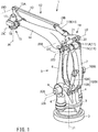
FIG. 1 is a perspective view of an industrial robot in accordance with an embodiment of the present invention in a view from the diagonal rear. -
FIG. 2 is a perspective view of the industrial robot inFIG. 1 in a view from the diagonal front. -
FIG. 3 is a schematic view illustrating a link structure of the industrial robot inFIG. 1 . -
FIG. 4 is an enlarged side view illustrating an upper arm mechanism of the industrial robot inFIG. 1 . -
FIG. 5 is a top view of the upper arm mechanism inFIG. 4 cutting away part of the same. -
FIG. 6 is an enlarged side view illustrating the lower half part of the lower arm mechanism of the industrial robot inFIG. 1 . -
FIG. 7 is a vertical section view of the lower half part of the lower arm mechanism inFIG. 6 in a view from the front. -
FIG. 8 is a vertical section view of the lower half part of the lower arm mechanism inFIG. 6 in a view from the rear. -
FIG. 9 is a schematic view illustrating a link structure in accordance with a variation of the industrial robot inFIG. 1 . - Hereunder, an industrial robot in accordance with an embodiment of the present invention will be described referring to the drawings.
- Note that the robot in accordance with the embodiment which will be described hereunder has four drive axles (four-axle robot), being suitable for a palletizing robot used to place a plurality of objects on a palette, for example. However, a scope of application of an industrial robot according to the present invention is not limited to the palletizing robot and it can be widely applied to industrial robots comprising an arm mechanism having a parallel link structure.
- As illustrated in
FIG. 1 to FIG. 3 , arobot 1 in accordance with this embodiment has abase 2 installed on a floor surface and abase portion 3 is provided on thebase 2. As illustrated inFIG. 3 , thebase portion 3 is capable of rotating about a vertical axis line J1 with respect to thebase 2. As illustrated inFIG. 1 andFIG. 7 , a rotational force to thebase portion 3 is applied by a pair of servo motors (drive source) 4 arranged on the right and left with the vertical axis line J1 sandwiched. - The
robot 1 according to this embodiment comprises a lower arm having a first parallel link structure and a lower side part of the first parallel link structure is formed of thebase portion 3. - As illustrated in
FIG. 3 , the first parallel link structure configuring alower arm mechanism 5 has a firstlower arm 6 configuring its front side part and a secondlower arm 7 configuring its rear side part. A lower end of the firstlower arm 6 is connected to thebase portion 3 so as to rotate about a horizontal axis line J2A. A lower end of a secondlower arm 7 is connected to thebase portion 3 so as to rotate about a horizontal axis line J2B. As illustrated inFIG. 1 , the firstlower arm 6 is rotationally driven about the horizontal axis line J2A with respect to thebase portion 3 by a servo motor (drive source) 8 provided to thebase portion 3. - As illustrated in
FIG. 1 ,FIG. 2 , andFIG. 7 , therobot 1 further comprises a lower arm biasing unit (balancer) 9 for applying a biasing force against a forward inclining operation of the secondlower arm 7 to the secondlower arm 7 configuring the rear side part of the first parallel link structure configuring thelower arm mechanism 5. The lowerarm biasing unit 9 comprises a pair of right andleft gas springs 10. A rear end portion of acylinder 10A of thegas spring 10 is rotatably connected to the secondlower arm 7 and also a tip end portion of apiston 10B of thegas spring 10 is rotatably connected to thebase portion 3. - As illustrated in
FIG. 2 andFIG. 4 , an upper side part of the first parallel link structure configuring thelower arm mechanism 5 is configured by anintermediate connection portion 11. Theintermediate connection portion 11 comprises alower protrusion portion 11A, afront projection portion 11B, and arear projection portion 11C. An upper end portion of the firstlower arm 6 is connected to thelower protrusion portion 11A of theintermediate connection portion 11 so as to rotate about a horizontal axis line J2C. An upper end portion of the secondlower arm 7 is connected to therear projection portion 11C of theintermediate connection portion 11 so as to rotate about a horizontal axis line J2D. - As illustrated in
FIG. 3 , the first parallel link structure is formed with the four horizontal axis lines J2A, J2B, J2C, J2D as the vertexes. When the firstlower arm 6 is operated so as to be inclined to the frtor to the rear by theservo motor 8, the upper side part of the first link structure (the part connecting the horizontal axis line J2C and the horizontal axis line J2D) rocks back and forth while maintaining its inclination. Namely, theintermediate connection portion 11 maintains the same posture regardless of the inclining operation of thelower arm mechanism 5. - As illustrated in
FIG. 1 to FIG. 5 , therobot 1 further comprises anupper arm mechanism 12 having the second parallel link structure. The upper side part of the second parallel link structure configuring theupper arm mechanism 12 is configured by an armauxiliary link 13. A proximal end portion of the upperauxiliary link 13 is connected to thefront projection portion 11B of theintermediate connection portion 11 so as to rotate about a horizontal axis line J3B. The lower side part of the second parallel link structure configuring theupper arm mechanism 12 is configured by anupper arm 14. A proximal end portion of theupper arm 14 is connected to the center part of theintermediate connection portion 11 so as to rotate about a horizontal axis line J3A. - The distal side portion of the second parallel link structure configuring the
upper arm mechanism 12 is configured by awrist portion 15. Namely, one apex of a supportingmember 15A, which is substantially triangle-shaped, of thewrist portion 15 is connected to the tip end portion of theupper arm 14 so as to rotate about the horizontal axis line J3C. Another apex of the supportingmember 15A of thewrist portion 15 is connected to the tip end portion of the upperauxiliary link 13 so as to rotate about a horizontal axis line J3D. - As illustrated in
FIG. 5 , theupper arm 14 is driven so as to rotate about the horizontal axis line J3A with respect to theintermediate connection portion 11 by a servo motor (drive source) 16 disposed on theintermediate connection portion 11. As illustrated inFIG. 3 andFIG. 4 , the second parallel link mechanism is formed with the four horizontal axis lines J3B, J3A, J3C, and J3D as apexes. Therefore, when theupper arm 14 is driven so as to rotate with respect to theintermediate connection portion 11 by theservo motor 16, thewrist portion 15 rocks vertically while maintaining its posture. - A servo motor (drive source) 17 disposed at the supporting
member 15A and arotary body 18 driven so as to rotate about a vertical axis line J4 by theservo motor 17. As described above, the supportingmember 14A of thewrist portion 14 rocks vertically while maintaining its inclination. Therefore, the vertical axis line J4 of therotary body 18 of thewrist portion 14 is always maintained in the vertical direction. - Note that, even when the
lower arm mechanism 5 performs a tilting operation, the posture of theupper arm 14 of theupper arm mechanism 12 does not change and also a gravity load to theupper arm 14 does not change, since thelower arm mechanism 5 has a parallel link structure as described above. Namely, even when thelower arm 6 is driven so as to rotate about the horizontal axis line J2A corresponding to the second axis of therobot 1, torque about the horizontal axis line J3A corresponding to the third axis of therobot 1 does not change. - As illustrated in
FIG. 1 andFIG. 2 , therobot 1 according to this embodiment further includes an upper arm biasing unit (balancer) 19 configured to apply an emerging force against a rotational operation in the direction that thewrist portion 15 descends to theupper arm 14 configuring the lower side part of the second parallel link structure of theupper arm mechanism 12. Note that theupper arm 14 is an arm which is directly driven by theservo motor 16, as described above. - As illustrated in
FIG. 3 , theupper arm 14 has anarm extension portion 14A extending exceeding the horizontal axis line J3A as a rotational axis line of theupper arm 14 on the proximal end side of theupper arm 14. An upperarm biasing unit 19 is configured to apply a biasing force to thearm extension portion 14A. - The upper
arm biasing unit 19 includes agas spring 20. The rear end portion of acylinder 20A of thegas spring 20 is connected to one end of agas spring support 21 the other end of which is fixed to thecenter connection portion 11 so as to rotate about a horizontal axis line L0. The tip end portion of apiston 20B of thegas spring 20 is connected to thearm extension portion 14A and a biasing force of thegas spring 20 acts in a direction that thearm extension portion 14A is pressed in steadily. - Note that the
gas spring support 21 may be connected to thecenter connection portion 11 after thegas spring support 21 is formed separately from thecenter connection portion 11 and also thegas spring support 21 may be formed integrally with thecenter connection portion 11 from the beginning. - The upper
arm biasing unit 19 is configured detachably. Namely, the rear end portion of thecylinder 20A of thegas spring 20 is separatably connected to thegas spring support 21, and the tip end portion of thepiston 20B of thegas spring 20 is separatably connected to thearm extension portion 14. Thereby, the upperarm biasing unit 19 can be suitably removed as needed. - Note that, although the
gas spring support 21 protrudes upward from theintermediate connection portion 11 as illustrated inFIG. 4 , the protrusion range of thegas spring support 21 is limited to a range of not making trouble in operation of therobot 1. - In the
robot 1 according to this embodiment, the firstlower arm 6 and the secondlower arm 7 configuring thelower arm mechanism 5 have the same strength against the torsion of the firstlower arm 6 and the secondlower arm 7. Namely, as illustrated inFIG. 1 andFIG. 6 , the firstlower arm 6 and the secondlower arm 7 are formed of members of substantially equal thickness. - The first
lower arm 6 and the secondlower arm 7 are formed in a hollow structure with a U-section, respectively. Thereby, the casting performance of the both arms in casting is improved. - As illustrated in
FIG. 8 , the lower end portion of the firstlower arm 6 which is directly driven by theservo motor 8 is connected to thebase portion 3 by a single supportingportion 22 to have a cantilever structure. This configuration can be realized easily by forming the firstlower arm 6 and the secondlower arm 7 with members of substantially equal thickness as described above thereby making the firstlower arm 6 thinner than before. - As illustrated in
FIG. 1 andFIG. 7 , the lowerarm biasing unit 9 is configured to apply a biasing force to the secondlower arm 7 not to the firstlower arm 6 which is directly driven by theservo motor 8. This configuration can be realized easily by forming the firstlower arm 6 and the secondlower arm 7 with members of substantially equal thickness as described above thereby making the secondlower arm 7 thicker than before. -
FIG. 9 illustrates a variant example of the embodiment above. In this example, an emerging force of the upperarm biasing unit 19 acts in a direction that thearm extension portion 14A is attracted. Thereby, an emerging force against a rotational operation in a direction that thewrist portion 15 descends is applied to theupper arm 14. Namely, thegas spring 20 of the upperarm biasing unit 19 acts in a direction that thepiston 20B of thegas spring 20 is withdrawn. - In another variant example, the lower
arm biasing unit 9 can be disposed so as to apply a biasing force to the firstlower arm 6 on the front side not to the secondlower arm 7 on the rear side. - In another variant example, in the upper
arm biasing unit 19, a balancer using a spring or a counterbalance mechanism using a weight can be used instead of thegas spring 20. - According to the embodiment and variant examples thereof above, a biasing force against a rotational operation in a direction that the
wrist portion 15 descends is applied to theupper arm 14 by the upperarm biasing unit 19. Therefore, the upper limit of the range of the portable mass of an object can be raised even though the capacity of theservo motor 16 driving theupper arm 14 is increased or the reduction ratio is not increased. Namely, the range of the portable mass of an object can be expanded without enlarging an arm driving motor and decreasing an arm operation speed. -
- 1 ... robot
- 2 ... base
- 3 ... base portion
- 4, 8, 16, 17 ... servo motor (drive source)
- 5 ... lower arm mechanism
- 6 ... first lower arm
- 7 ... second lower arm
- 9 ... lower arm biasing unit (balancer)
- 10, 20 ... gas spring
- 10A, 20A ... cylinder of gas spring
- 10B, 20B ... piston of gas spring
- 11 ... intermediate connection portion
- 11A ... lower protrusion portion of intermediate connection portion
- 11B ... front protrusion portion of intermediate connection portion
- 11C ... rear protrusion portion of intermediate connection portion
- 12 ... upper arm mechanism
- 13 ... upper auxiliary link
- 14 ... upper arm
- 14A ... arm extension portion
- 15 ... wrist portion
- 15A ... supporting member of wrist portion
- 18 ... rotary body
- 19 ... upper arm biasing unit (balancer)
- 21 ... gas spring support
- 22 ... supporting member of first lower arm
- J1, J4 ... vertical axis line
- J2A, J2B, J2C, J2D, J3A, J3B, J3C, J3D, L0 ... horizontal axis line
Claims (15)
- An industrial robot comprising:a lower arm mechanism having a first parallel link structure;an upper arm mechanism having a second parallel link structure;a base portion forming a lower side part of the first parallel link structure;a wrist portion forming a distal side part of the second parallel link structure;an intermediate connection portion forming an upper side part of the first parallel link structure and a proximal side part of the second parallel link structure; andan upper arm biasing unit configured to apply a biasing force against a rotating operation in a direction that the wrist portion descends to an upper arm configuring a lower side part or an upper side part of the second parallel link structure.
- The industrial robot according to claim 1, wherein the upper arm has an arm extension portion extending so as to exceed a rotational axis of the upper arm on a proximal end side of the upper arm,
and whrein the upper arm biasing unit is configured so as to apply a biasing force to the arm extension portion. - The industrial robot according to claim 2, wherein the biasing force of the upper arm biasing unit works in a direction that the arm extension portion is pressed in.
- The industrial robot according to claim 2, wherein the biasing force of the upper arm biasing unit works in a direction that the arm extension portion is attracted.
- The industrial robot according to any one of claims 1 to 4, wherein the upper arm biasing unit has a gas spring.
- The industrial robot according to claim 5, wherein the gas spring has a cylinder connected to the intermediate connection portion side and a piston connected to the arm extension portion side.
- The industrial robot according to any one of claims 1 to 6, wherein the upper arm biasing unit is configured detachably.
- The industrial robot according to any one of claims 1 to 7, wherein the upper arm biasing unit regularly applies a biasing force to the upper arm.
- The industrial robot according to any one of claims 1 to 8, wherein the upper arm to which the biasing force is applied by the upper arm biasing unit is an arm directly driven by a drive source.
- The industrial robot according to any one of claims 1 to 9, wherein the first parallel link structure has a first lower arm configuring a front side part thereof and a second lower arm configuring a rear side part thereof, and
wherein the first lower arm and the second lower arm having a same strength against their torsion. - The industrial robot according to claim 10, wherein at least one of the first lower arm and the second lower arm is formed to have a hollow structure.
- The industrial robot according to claim 10 or 11, wherein one of the first lower arm and the second lower arm which is directly driven by a drive source is connected to the base portion so as to have a cantilever structure.
- The industrial robot according to any one of claims 1 to 12, further comprising a lower arm biasing unit configured to apply a biasing force against a forward inclining operation of the lower arm to a lower arm configuring a front side part or a rear side part of the first parallel link structure.
- The industrial robot according to claim 13, wherein the first parallel link structure has a first lower arm configuring its front side part and a second lower arm configuring its rear side part, and
wherein the lower arm biasing unit applies a biasing force to one of the first lower arm and the second lower arm which is different from either one which is directly driven by a drive source. - The industrial robot according to any one of claims 1 to 14, wherein the base portion is capable of rotating about a vertical axis line, and
Wherein the industrial robot having a pair of left and right drive sources configured to apply a rotational drive force to the base portion.
Applications Claiming Priority (2)
| Application Number | Priority Date | Filing Date | Title |
|---|---|---|---|
| JP2014092297A JP6518037B2 (en) | 2014-04-28 | 2014-04-28 | Industrial robot |
| PCT/JP2015/060092 WO2015166757A1 (en) | 2014-04-28 | 2015-03-31 | Industrial robot |
Publications (3)
| Publication Number | Publication Date |
|---|---|
| EP3138670A1 true EP3138670A1 (en) | 2017-03-08 |
| EP3138670A4 EP3138670A4 (en) | 2018-04-25 |
| EP3138670B1 EP3138670B1 (en) | 2024-04-24 |
Family
ID=54358494
Family Applications (1)
| Application Number | Title | Priority Date | Filing Date |
|---|---|---|---|
| EP15786446.3A Active EP3138670B1 (en) | 2014-04-28 | 2015-03-31 | Industrial robot |
Country Status (7)
| Country | Link |
|---|---|
| US (1) | US11077550B2 (en) |
| EP (1) | EP3138670B1 (en) |
| JP (1) | JP6518037B2 (en) |
| KR (1) | KR101988709B1 (en) |
| CN (1) | CN106255575B (en) |
| TW (1) | TWI624340B (en) |
| WO (1) | WO2015166757A1 (en) |
Families Citing this family (28)
| Publication number | Priority date | Publication date | Assignee | Title |
|---|---|---|---|---|
| KR101734241B1 (en) * | 2015-12-10 | 2017-05-11 | 현대자동차 주식회사 | Trunk lid hinge intellectual loader unit |
| CN106272403A (en) * | 2016-09-20 | 2017-01-04 | 安徽欢颜机器人有限公司 | A kind of punching press industry is with four axle robots |
| JP6851615B2 (en) * | 2016-09-30 | 2021-03-31 | 三鷹光器株式会社 | Medical stand device |
| US10765537B2 (en) * | 2016-11-11 | 2020-09-08 | Sarcos Corp. | Tunable actuator joint modules having energy recovering quasi-passive elastic actuators for use within a robotic system |
| US10828767B2 (en) | 2016-11-11 | 2020-11-10 | Sarcos Corp. | Tunable actuator joint modules having energy recovering quasi-passive elastic actuators with internal valve arrangements |
| US10821614B2 (en) | 2016-11-11 | 2020-11-03 | Sarcos Corp. | Clutched joint modules having a quasi-passive elastic actuator for a robotic assembly |
| WO2018161196A1 (en) * | 2017-03-05 | 2018-09-13 | 肖丽芳 | Robot mechanism for family service |
| FR3063666B1 (en) * | 2017-03-08 | 2021-05-07 | Neoditech | DEVICE FOR HANDLING AND / OR POSITIONING OF OBJECTS |
| TWI630080B (en) * | 2017-07-11 | 2018-07-21 | 朱朝濱 | All-in-one robot arm assembly structure |
| KR102055291B1 (en) * | 2017-12-18 | 2019-12-12 | (주)로보티즈 | Multi-joint robot |
| CN108972511A (en) * | 2018-08-27 | 2018-12-11 | 聊城大学 | A kind of robot palletizer and its application method |
| KR102135216B1 (en) * | 2018-10-19 | 2020-07-20 | 하이윈 테크놀로지스 코포레이션 | Robotic arm |
| CN109605110B (en) * | 2018-12-25 | 2022-02-01 | 中智未来(天津)机器人科技有限公司 | Industrial robot for feeding and discharging materials on numerical control machine tool |
| CN110393460B (en) * | 2019-08-23 | 2021-04-27 | 珠海市快端科技有限公司 | Servo-driven mechanical arm and knockout machine using same |
| JP7307642B2 (en) * | 2019-09-25 | 2023-07-12 | 日本電子株式会社 | NMR probe carrier and NMR measurement system |
| CN112743533A (en) * | 2019-10-29 | 2021-05-04 | 天津新松机器人自动化有限公司 | Intelligent stacking robot |
| CN110978049A (en) * | 2019-12-12 | 2020-04-10 | 台州学院 | A mobile clamping device for machining mechanical parts with adjustable display angle |
| JP7281420B2 (en) * | 2020-01-09 | 2023-05-25 | 株式会社ダイヘン | work aid |
| CN115210046A (en) | 2020-03-02 | 2022-10-18 | 柿子技术公司 | Compact type transverse moving robot |
| CN111300478B (en) * | 2020-04-01 | 2021-04-02 | 朱静舟 | Rotating structure for joint of small robot |
| CN112757282A (en) * | 2021-01-15 | 2021-05-07 | 赵永杰 | Heavy-load robot driven in parallel |
| CN113749773B (en) * | 2021-08-17 | 2023-03-10 | 浙江理工大学 | Two-rotation one-movement remote motion center mechanism |
| CN114750128B (en) * | 2022-06-16 | 2022-09-09 | 中铁工程服务有限公司 | Robot and duct piece assembling system |
| US12172298B2 (en) | 2022-11-04 | 2024-12-24 | Sarcos Corp. | Robotic end-effector having dynamic stiffening elements with resilient spacers for conforming object interaction |
| US11924023B1 (en) | 2022-11-17 | 2024-03-05 | Sarcos Corp. | Systems and methods for redundant network communication in a robot |
| USD1128754S1 (en) * | 2023-06-06 | 2026-06-02 | Famatec S.R.L. | Manipulator arm |
| CN118528242B (en) * | 2024-06-24 | 2025-01-14 | 三维汉界机器(山东)股份有限公司 | An industrial robot with a planar multi-link mechanism with integrated kinematic pairs |
| CN118578359A (en) * | 2024-06-27 | 2024-09-03 | 三维汉界机器(山东)股份有限公司 | An industrial robot with a planar parallel mechanism |
Family Cites Families (35)
| Publication number | Priority date | Publication date | Assignee | Title |
|---|---|---|---|---|
| JPS5952306B2 (en) | 1979-09-11 | 1984-12-19 | 株式会社佐々木製作所 | balancer |
| JPS57140996U (en) * | 1981-02-25 | 1982-09-03 | ||
| US4592697A (en) * | 1983-04-26 | 1986-06-03 | Kabushiki Kaisha Kobe Seiko Sho | Gravity balancing device for rocking arm |
| JPS6112691U (en) * | 1984-06-27 | 1986-01-24 | 株式会社日立製作所 | Gravity balance mechanism of articulated robot |
| JPH061344Y2 (en) * | 1987-12-28 | 1994-01-12 | 三井造船株式会社 | Lifting equipment |
| JPH0419092A (en) * | 1990-05-11 | 1992-01-23 | Hitachi Ltd | gravity balance device |
| JPH03103181U (en) * | 1990-02-07 | 1991-10-25 | ||
| JP2516715B2 (en) * | 1991-09-24 | 1996-07-24 | 三井造船株式会社 | Load balancer |
| US5314291A (en) * | 1991-09-24 | 1994-05-24 | Mitsui Engineering & Shipbuilding Co., Ltd. | Load balancer |
| JP2553995Y2 (en) * | 1993-05-10 | 1997-11-12 | 株式会社明電舎 | Industrial manipulator |
| JP3266714B2 (en) * | 1993-10-08 | 2002-03-18 | 株式会社小松製作所 | Manipulator attitude control device |
| JPH07227791A (en) * | 1994-02-22 | 1995-08-29 | Mitsubishi Electric Corp | Robot equipment |
| DE4428488C1 (en) * | 1994-08-12 | 1995-10-26 | Hans Richter | Wrist for the working hand of a robot |
| JPH08197463A (en) * | 1995-01-26 | 1996-08-06 | Fanuc Ltd | Link devices such as industrial robots |
| JPH10180665A (en) * | 1996-12-27 | 1998-07-07 | Aichi Corp | Work arm |
| JPH11262889A (en) * | 1998-03-17 | 1999-09-28 | Mitsubishi Heavy Ind Ltd | Industrial articulated robot |
| DE10007251A1 (en) * | 2000-02-17 | 2001-08-23 | Kuka Roboter Gmbh | Device for weight balancing of robot arm has unit for easy fitting and removal of at least one additional exchangeable coil spring in cylinder |
| JP2003039351A (en) | 2001-07-27 | 2003-02-13 | Kawasaki Heavy Ind Ltd | Robot with offset |
| JP2003071759A (en) * | 2001-08-28 | 2003-03-12 | Seiko Epson Corp | Handling device |
| JP3813542B2 (en) * | 2002-05-31 | 2006-08-23 | 株式会社不二越 | Industrial robot |
| JP3953931B2 (en) * | 2002-10-02 | 2007-08-08 | 株式会社不二越 | Industrial robot |
| JP3988768B2 (en) * | 2004-12-16 | 2007-10-10 | セイコーエプソン株式会社 | Link drive mechanism and industrial robot using the same |
| JP4719010B2 (en) * | 2005-01-21 | 2011-07-06 | 日本電産サンキョー株式会社 | Industrial robot |
| US7331750B2 (en) * | 2005-03-21 | 2008-02-19 | Michael Merz | Parallel robot |
| JP2007089465A (en) | 2005-09-28 | 2007-04-12 | Iseki & Co Ltd | Arm type work machine of work vehicle |
| JP4148280B2 (en) * | 2005-10-18 | 2008-09-10 | セイコーエプソン株式会社 | Parallel link mechanism and industrial robot |
| CN100500388C (en) * | 2005-10-19 | 2009-06-17 | 精工爱普生株式会社 | Parallel Link Mechanism and Industrial Robot |
| JP4232795B2 (en) * | 2005-10-19 | 2009-03-04 | セイコーエプソン株式会社 | Parallel link mechanism and industrial robot |
| JP4291344B2 (en) * | 2006-08-31 | 2009-07-08 | ファナック株式会社 | Industrial robot |
| JP2008142829A (en) * | 2006-12-11 | 2008-06-26 | National Institute Of Advanced Industrial & Technology | Daily life support manipulator device |
| JP2011031372A (en) * | 2009-08-06 | 2011-02-17 | Yaskawa Electric Corp | Industrial robot |
| JP2011125966A (en) * | 2009-12-18 | 2011-06-30 | Kansai Univ | Robot |
| CN101954639B (en) * | 2010-09-27 | 2012-07-04 | 华中科技大学 | Transmission mechanism for hollow wrist of industrial robot |
| JP5845026B2 (en) * | 2011-09-06 | 2016-01-20 | トヨタ自動車株式会社 | Load compensation mechanism |
| DE102011054910B4 (en) * | 2011-10-28 | 2013-10-10 | Ovesco Endoscopy Ag | Magnetic end effector and means for guiding and positioning same |
-
2014
- 2014-04-28 JP JP2014092297A patent/JP6518037B2/en active Active
-
2015
- 2015-03-31 WO PCT/JP2015/060092 patent/WO2015166757A1/en not_active Ceased
- 2015-03-31 CN CN201580023394.5A patent/CN106255575B/en active Active
- 2015-03-31 KR KR1020167032916A patent/KR101988709B1/en active Active
- 2015-03-31 US US15/307,438 patent/US11077550B2/en active Active
- 2015-03-31 EP EP15786446.3A patent/EP3138670B1/en active Active
- 2015-04-22 TW TW104112928A patent/TWI624340B/en active
Also Published As
| Publication number | Publication date |
|---|---|
| US20170050314A1 (en) | 2017-02-23 |
| JP2015208814A (en) | 2015-11-24 |
| WO2015166757A1 (en) | 2015-11-05 |
| TWI624340B (en) | 2018-05-21 |
| EP3138670A4 (en) | 2018-04-25 |
| EP3138670B1 (en) | 2024-04-24 |
| US11077550B2 (en) | 2021-08-03 |
| KR20160148636A (en) | 2016-12-26 |
| CN106255575A (en) | 2016-12-21 |
| TW201600274A (en) | 2016-01-01 |
| JP6518037B2 (en) | 2019-05-22 |
| CN106255575B (en) | 2019-11-15 |
| KR101988709B1 (en) | 2019-06-12 |
Similar Documents
| Publication | Publication Date | Title |
|---|---|---|
| EP3138670B1 (en) | Industrial robot | |
| CN110143546B (en) | wall panel truck | |
| CN105835048A (en) | Robot | |
| CN207841335U (en) | A kind of Novel machine machinery claw | |
| CN104924297A (en) | High-speed two-degree-of-freedom planar transverse-movement robot mechanism | |
| CN114905543A (en) | Balancing mechanism for robotic auxiliary device | |
| KR101480346B1 (en) | gravity compensation device of vertical articulated robot with a parallel link structure | |
| CN113603035A (en) | Overturning platform and overturning method | |
| JPH07205711A (en) | Heavy load handling device | |
| CN112249980B (en) | Anti-tipping method and anti-tipping mechanism for three-fulcrum electric forklift | |
| KR101805606B1 (en) | Gripper having enhanced Heat resistance, impact resistance and wear resistance | |
| US20110158758A1 (en) | Lifting Machine Base Assembly for a Machine Tool | |
| JP6976096B2 (en) | Container gripping device | |
| CN112658450B (en) | Spot welding device with easy position change | |
| CN109570288A (en) | Bending machine | |
| CN101574808A (en) | Manipulator auxiliary device | |
| JP2009113898A (en) | Slide fork device | |
| CN211846923U (en) | Cantilever crane and machining system | |
| CN209814136U (en) | Drive platform and robot | |
| CN220766415U (en) | Maintenance mobile cart | |
| JP2007130729A (en) | Industrial robot | |
| CN210850235U (en) | an electrical manipulator | |
| JP4213538B2 (en) | Pallet changer | |
| CN104385039A (en) | Piston overturning and clamping feeding mechanism | |
| CN211545071U (en) | A workpiece turning device |
Legal Events
| Date | Code | Title | Description |
|---|---|---|---|
| STAA | Information on the status of an ep patent application or granted ep patent |
Free format text: STATUS: THE INTERNATIONAL PUBLICATION HAS BEEN MADE |
|
| PUAI | Public reference made under article 153(3) epc to a published international application that has entered the european phase |
Free format text: ORIGINAL CODE: 0009012 |
|
| STAA | Information on the status of an ep patent application or granted ep patent |
Free format text: STATUS: REQUEST FOR EXAMINATION WAS MADE |
|
| 17P | Request for examination filed |
Effective date: 20161125 |
|
| AK | Designated contracting states |
Kind code of ref document: A1 Designated state(s): AL AT BE BG CH CY CZ DE DK EE ES FI FR GB GR HR HU IE IS IT LI LT LU LV MC MK MT NL NO PL PT RO RS SE SI SK SM TR |
|
| AX | Request for extension of the european patent |
Extension state: BA ME |
|
| DAV | Request for validation of the european patent (deleted) | ||
| DAX | Request for extension of the european patent (deleted) | ||
| A4 | Supplementary search report drawn up and despatched |
Effective date: 20180323 |
|
| RIC1 | Information provided on ipc code assigned before grant |
Ipc: B25J 9/04 20060101AFI20180319BHEP Ipc: B25J 9/06 20060101ALI20180319BHEP Ipc: B25J 9/10 20060101ALI20180319BHEP |
|
| STAA | Information on the status of an ep patent application or granted ep patent |
Free format text: STATUS: EXAMINATION IS IN PROGRESS |
|
| 17Q | First examination report despatched |
Effective date: 20190711 |
|
| REG | Reference to a national code |
Ref country code: DE Ref legal event code: R079 Free format text: PREVIOUS MAIN CLASS: B25J0019000000 Ipc: B25J0009040000 Ref document number: 602015088443 Country of ref document: DE |
|
| GRAP | Despatch of communication of intention to grant a patent |
Free format text: ORIGINAL CODE: EPIDOSNIGR1 |
|
| STAA | Information on the status of an ep patent application or granted ep patent |
Free format text: STATUS: GRANT OF PATENT IS INTENDED |
|
| RIC1 | Information provided on ipc code assigned before grant |
Ipc: B25J 19/00 20060101ALI20231107BHEP Ipc: B25J 9/06 20060101ALI20231107BHEP Ipc: B25J 9/10 20060101ALI20231107BHEP Ipc: B25J 9/04 20060101AFI20231107BHEP |
|
| INTG | Intention to grant announced |
Effective date: 20231124 |
|
| GRAS | Grant fee paid |
Free format text: ORIGINAL CODE: EPIDOSNIGR3 |
|
| GRAA | (expected) grant |
Free format text: ORIGINAL CODE: 0009210 |
|
| STAA | Information on the status of an ep patent application or granted ep patent |
Free format text: STATUS: THE PATENT HAS BEEN GRANTED |
|
| AK | Designated contracting states |
Kind code of ref document: B1 Designated state(s): AL AT BE BG CH CY CZ DE DK EE ES FI FR GB GR HR HU IE IS IT LI LT LU LV MC MK MT NL NO PL PT RO RS SE SI SK SM TR |
|
| REG | Reference to a national code |
Ref country code: GB Ref legal event code: FG4D |
|
| REG | Reference to a national code |
Ref country code: CH Ref legal event code: EP |
|
| REG | Reference to a national code |
Ref country code: DE Ref legal event code: R096 Ref document number: 602015088443 Country of ref document: DE |
|
| REG | Reference to a national code |
Ref country code: IE Ref legal event code: FG4D |
|
| REG | Reference to a national code |
Ref country code: LT Ref legal event code: MG9D |
|
| REG | Reference to a national code |
Ref country code: NL Ref legal event code: MP Effective date: 20240424 |
|
| REG | Reference to a national code |
Ref country code: AT Ref legal event code: MK05 Ref document number: 1679117 Country of ref document: AT Kind code of ref document: T Effective date: 20240424 |
|
| PG25 | Lapsed in a contracting state [announced via postgrant information from national office to epo] |
Ref country code: NL Free format text: LAPSE BECAUSE OF FAILURE TO SUBMIT A TRANSLATION OF THE DESCRIPTION OR TO PAY THE FEE WITHIN THE PRESCRIBED TIME-LIMIT Effective date: 20240424 |
|
| PG25 | Lapsed in a contracting state [announced via postgrant information from national office to epo] |
Ref country code: NL Free format text: LAPSE BECAUSE OF FAILURE TO SUBMIT A TRANSLATION OF THE DESCRIPTION OR TO PAY THE FEE WITHIN THE PRESCRIBED TIME-LIMIT Effective date: 20240424 |
|
| PG25 | Lapsed in a contracting state [announced via postgrant information from national office to epo] |
Ref country code: IS Free format text: LAPSE BECAUSE OF FAILURE TO SUBMIT A TRANSLATION OF THE DESCRIPTION OR TO PAY THE FEE WITHIN THE PRESCRIBED TIME-LIMIT Effective date: 20240824 |
|
| PG25 | Lapsed in a contracting state [announced via postgrant information from national office to epo] |
Ref country code: BG Free format text: LAPSE BECAUSE OF FAILURE TO SUBMIT A TRANSLATION OF THE DESCRIPTION OR TO PAY THE FEE WITHIN THE PRESCRIBED TIME-LIMIT Effective date: 20240424 |
|
| PG25 | Lapsed in a contracting state [announced via postgrant information from national office to epo] |
Ref country code: HR Free format text: LAPSE BECAUSE OF FAILURE TO SUBMIT A TRANSLATION OF THE DESCRIPTION OR TO PAY THE FEE WITHIN THE PRESCRIBED TIME-LIMIT Effective date: 20240424 Ref country code: FI Free format text: LAPSE BECAUSE OF FAILURE TO SUBMIT A TRANSLATION OF THE DESCRIPTION OR TO PAY THE FEE WITHIN THE PRESCRIBED TIME-LIMIT Effective date: 20240424 |
|
| PG25 | Lapsed in a contracting state [announced via postgrant information from national office to epo] |
Ref country code: GR Free format text: LAPSE BECAUSE OF FAILURE TO SUBMIT A TRANSLATION OF THE DESCRIPTION OR TO PAY THE FEE WITHIN THE PRESCRIBED TIME-LIMIT Effective date: 20240725 |
|
| PG25 | Lapsed in a contracting state [announced via postgrant information from national office to epo] |
Ref country code: PT Free format text: LAPSE BECAUSE OF FAILURE TO SUBMIT A TRANSLATION OF THE DESCRIPTION OR TO PAY THE FEE WITHIN THE PRESCRIBED TIME-LIMIT Effective date: 20240826 |
|
| PG25 | Lapsed in a contracting state [announced via postgrant information from national office to epo] |
Ref country code: ES Free format text: LAPSE BECAUSE OF FAILURE TO SUBMIT A TRANSLATION OF THE DESCRIPTION OR TO PAY THE FEE WITHIN THE PRESCRIBED TIME-LIMIT Effective date: 20240424 |
|
| PG25 | Lapsed in a contracting state [announced via postgrant information from national office to epo] |
Ref country code: AT Free format text: LAPSE BECAUSE OF FAILURE TO SUBMIT A TRANSLATION OF THE DESCRIPTION OR TO PAY THE FEE WITHIN THE PRESCRIBED TIME-LIMIT Effective date: 20240424 |
|
| PG25 | Lapsed in a contracting state [announced via postgrant information from national office to epo] |
Ref country code: PL Free format text: LAPSE BECAUSE OF FAILURE TO SUBMIT A TRANSLATION OF THE DESCRIPTION OR TO PAY THE FEE WITHIN THE PRESCRIBED TIME-LIMIT Effective date: 20240424 |
|
| PG25 | Lapsed in a contracting state [announced via postgrant information from national office to epo] |
Ref country code: LV Free format text: LAPSE BECAUSE OF FAILURE TO SUBMIT A TRANSLATION OF THE DESCRIPTION OR TO PAY THE FEE WITHIN THE PRESCRIBED TIME-LIMIT Effective date: 20240424 |
|
| PG25 | Lapsed in a contracting state [announced via postgrant information from national office to epo] |
Ref country code: PT Free format text: LAPSE BECAUSE OF FAILURE TO SUBMIT A TRANSLATION OF THE DESCRIPTION OR TO PAY THE FEE WITHIN THE PRESCRIBED TIME-LIMIT Effective date: 20240826 Ref country code: PL Free format text: LAPSE BECAUSE OF FAILURE TO SUBMIT A TRANSLATION OF THE DESCRIPTION OR TO PAY THE FEE WITHIN THE PRESCRIBED TIME-LIMIT Effective date: 20240424 Ref country code: NO Free format text: LAPSE BECAUSE OF FAILURE TO SUBMIT A TRANSLATION OF THE DESCRIPTION OR TO PAY THE FEE WITHIN THE PRESCRIBED TIME-LIMIT Effective date: 20240724 Ref country code: LV Free format text: LAPSE BECAUSE OF FAILURE TO SUBMIT A TRANSLATION OF THE DESCRIPTION OR TO PAY THE FEE WITHIN THE PRESCRIBED TIME-LIMIT Effective date: 20240424 Ref country code: IS Free format text: LAPSE BECAUSE OF FAILURE TO SUBMIT A TRANSLATION OF THE DESCRIPTION OR TO PAY THE FEE WITHIN THE PRESCRIBED TIME-LIMIT Effective date: 20240824 Ref country code: HR Free format text: LAPSE BECAUSE OF FAILURE TO SUBMIT A TRANSLATION OF THE DESCRIPTION OR TO PAY THE FEE WITHIN THE PRESCRIBED TIME-LIMIT Effective date: 20240424 Ref country code: GR Free format text: LAPSE BECAUSE OF FAILURE TO SUBMIT A TRANSLATION OF THE DESCRIPTION OR TO PAY THE FEE WITHIN THE PRESCRIBED TIME-LIMIT Effective date: 20240725 Ref country code: FI Free format text: LAPSE BECAUSE OF FAILURE TO SUBMIT A TRANSLATION OF THE DESCRIPTION OR TO PAY THE FEE WITHIN THE PRESCRIBED TIME-LIMIT Effective date: 20240424 Ref country code: ES Free format text: LAPSE BECAUSE OF FAILURE TO SUBMIT A TRANSLATION OF THE DESCRIPTION OR TO PAY THE FEE WITHIN THE PRESCRIBED TIME-LIMIT Effective date: 20240424 Ref country code: BG Free format text: LAPSE BECAUSE OF FAILURE TO SUBMIT A TRANSLATION OF THE DESCRIPTION OR TO PAY THE FEE WITHIN THE PRESCRIBED TIME-LIMIT Effective date: 20240424 Ref country code: AT Free format text: LAPSE BECAUSE OF FAILURE TO SUBMIT A TRANSLATION OF THE DESCRIPTION OR TO PAY THE FEE WITHIN THE PRESCRIBED TIME-LIMIT Effective date: 20240424 Ref country code: RS Free format text: LAPSE BECAUSE OF FAILURE TO SUBMIT A TRANSLATION OF THE DESCRIPTION OR TO PAY THE FEE WITHIN THE PRESCRIBED TIME-LIMIT Effective date: 20240724 |
|
| PG25 | Lapsed in a contracting state [announced via postgrant information from national office to epo] |
Ref country code: DK Free format text: LAPSE BECAUSE OF FAILURE TO SUBMIT A TRANSLATION OF THE DESCRIPTION OR TO PAY THE FEE WITHIN THE PRESCRIBED TIME-LIMIT Effective date: 20240424 |
|
| PG25 | Lapsed in a contracting state [announced via postgrant information from national office to epo] |
Ref country code: EE Free format text: LAPSE BECAUSE OF FAILURE TO SUBMIT A TRANSLATION OF THE DESCRIPTION OR TO PAY THE FEE WITHIN THE PRESCRIBED TIME-LIMIT Effective date: 20240424 |
|
| PG25 | Lapsed in a contracting state [announced via postgrant information from national office to epo] |
Ref country code: CZ Free format text: LAPSE BECAUSE OF FAILURE TO SUBMIT A TRANSLATION OF THE DESCRIPTION OR TO PAY THE FEE WITHIN THE PRESCRIBED TIME-LIMIT Effective date: 20240424 |
|
| PG25 | Lapsed in a contracting state [announced via postgrant information from national office to epo] |
Ref country code: RO Free format text: LAPSE BECAUSE OF FAILURE TO SUBMIT A TRANSLATION OF THE DESCRIPTION OR TO PAY THE FEE WITHIN THE PRESCRIBED TIME-LIMIT Effective date: 20240424 Ref country code: SK Free format text: LAPSE BECAUSE OF FAILURE TO SUBMIT A TRANSLATION OF THE DESCRIPTION OR TO PAY THE FEE WITHIN THE PRESCRIBED TIME-LIMIT Effective date: 20240424 |
|
| REG | Reference to a national code |
Ref country code: DE Ref legal event code: R097 Ref document number: 602015088443 Country of ref document: DE |
|
| PG25 | Lapsed in a contracting state [announced via postgrant information from national office to epo] |
Ref country code: SM Free format text: LAPSE BECAUSE OF FAILURE TO SUBMIT A TRANSLATION OF THE DESCRIPTION OR TO PAY THE FEE WITHIN THE PRESCRIBED TIME-LIMIT Effective date: 20240424 |
|
| PG25 | Lapsed in a contracting state [announced via postgrant information from national office to epo] |
Ref country code: SM Free format text: LAPSE BECAUSE OF FAILURE TO SUBMIT A TRANSLATION OF THE DESCRIPTION OR TO PAY THE FEE WITHIN THE PRESCRIBED TIME-LIMIT Effective date: 20240424 Ref country code: SK Free format text: LAPSE BECAUSE OF FAILURE TO SUBMIT A TRANSLATION OF THE DESCRIPTION OR TO PAY THE FEE WITHIN THE PRESCRIBED TIME-LIMIT Effective date: 20240424 Ref country code: RO Free format text: LAPSE BECAUSE OF FAILURE TO SUBMIT A TRANSLATION OF THE DESCRIPTION OR TO PAY THE FEE WITHIN THE PRESCRIBED TIME-LIMIT Effective date: 20240424 Ref country code: EE Free format text: LAPSE BECAUSE OF FAILURE TO SUBMIT A TRANSLATION OF THE DESCRIPTION OR TO PAY THE FEE WITHIN THE PRESCRIBED TIME-LIMIT Effective date: 20240424 Ref country code: DK Free format text: LAPSE BECAUSE OF FAILURE TO SUBMIT A TRANSLATION OF THE DESCRIPTION OR TO PAY THE FEE WITHIN THE PRESCRIBED TIME-LIMIT Effective date: 20240424 Ref country code: CZ Free format text: LAPSE BECAUSE OF FAILURE TO SUBMIT A TRANSLATION OF THE DESCRIPTION OR TO PAY THE FEE WITHIN THE PRESCRIBED TIME-LIMIT Effective date: 20240424 |
|
| PLBE | No opposition filed within time limit |
Free format text: ORIGINAL CODE: 0009261 |
|
| STAA | Information on the status of an ep patent application or granted ep patent |
Free format text: STATUS: NO OPPOSITION FILED WITHIN TIME LIMIT |
|
| 26N | No opposition filed |
Effective date: 20250127 |
|
| PG25 | Lapsed in a contracting state [announced via postgrant information from national office to epo] |
Ref country code: SI Free format text: LAPSE BECAUSE OF FAILURE TO SUBMIT A TRANSLATION OF THE DESCRIPTION OR TO PAY THE FEE WITHIN THE PRESCRIBED TIME-LIMIT Effective date: 20240424 |
|
| PG25 | Lapsed in a contracting state [announced via postgrant information from national office to epo] |
Ref country code: SE Free format text: LAPSE BECAUSE OF FAILURE TO SUBMIT A TRANSLATION OF THE DESCRIPTION OR TO PAY THE FEE WITHIN THE PRESCRIBED TIME-LIMIT Effective date: 20240424 |
|
| PG25 | Lapsed in a contracting state [announced via postgrant information from national office to epo] |
Ref country code: MC Free format text: LAPSE BECAUSE OF FAILURE TO SUBMIT A TRANSLATION OF THE DESCRIPTION OR TO PAY THE FEE WITHIN THE PRESCRIBED TIME-LIMIT Effective date: 20240424 |
|
| REG | Reference to a national code |
Ref country code: CH Ref legal event code: H13 Free format text: ST27 STATUS EVENT CODE: U-0-0-H10-H13 (AS PROVIDED BY THE NATIONAL OFFICE) Effective date: 20251023 |
|
| PG25 | Lapsed in a contracting state [announced via postgrant information from national office to epo] |
Ref country code: LU Free format text: LAPSE BECAUSE OF NON-PAYMENT OF DUE FEES Effective date: 20250331 |
|
| GBPC | Gb: european patent ceased through non-payment of renewal fee |
Effective date: 20250331 |
|
| REG | Reference to a national code |
Ref country code: BE Ref legal event code: MM Effective date: 20250331 |
|
| PG25 | Lapsed in a contracting state [announced via postgrant information from national office to epo] |
Ref country code: GB Free format text: LAPSE BECAUSE OF NON-PAYMENT OF DUE FEES Effective date: 20250331 |
|
| PG25 | Lapsed in a contracting state [announced via postgrant information from national office to epo] |
Ref country code: FR Free format text: LAPSE BECAUSE OF NON-PAYMENT OF DUE FEES Effective date: 20250331 |
|
| PG25 | Lapsed in a contracting state [announced via postgrant information from national office to epo] |
Ref country code: BE Free format text: LAPSE BECAUSE OF NON-PAYMENT OF DUE FEES Effective date: 20250331 |
|
| PG25 | Lapsed in a contracting state [announced via postgrant information from national office to epo] |
Ref country code: CH Free format text: LAPSE BECAUSE OF NON-PAYMENT OF DUE FEES Effective date: 20250331 |
|
| PG25 | Lapsed in a contracting state [announced via postgrant information from national office to epo] |
Ref country code: IE Free format text: LAPSE BECAUSE OF NON-PAYMENT OF DUE FEES Effective date: 20250331 |
|
| PG25 | Lapsed in a contracting state [announced via postgrant information from national office to epo] |
Ref country code: IT Free format text: LAPSE BECAUSE OF FAILURE TO SUBMIT A TRANSLATION OF THE DESCRIPTION OR TO PAY THE FEE WITHIN THE PRESCRIBED TIME-LIMIT Effective date: 20240424 |
|
| PGFP | Annual fee paid to national office [announced via postgrant information from national office to epo] |
Ref country code: DE Payment date: 20260204 Year of fee payment: 12 |
|
| PG25 | Lapsed in a contracting state [announced via postgrant information from national office to epo] |
Ref country code: CY Free format text: LAPSE BECAUSE OF FAILURE TO SUBMIT A TRANSLATION OF THE DESCRIPTION OR TO PAY THE FEE WITHIN THE PRESCRIBED TIME-LIMIT Effective date: 20240424 |
|
| PG25 | Lapsed in a contracting state [announced via postgrant information from national office to epo] |
Ref country code: LT Free format text: LAPSE BECAUSE OF FAILURE TO SUBMIT A TRANSLATION OF THE DESCRIPTION OR TO PAY THE FEE WITHIN THE PRESCRIBED TIME-LIMIT Effective date: 20240424 |