JP6976096B2 - Container gripping device - Google Patents
Container gripping device Download PDFInfo
- Publication number
- JP6976096B2 JP6976096B2 JP2017144065A JP2017144065A JP6976096B2 JP 6976096 B2 JP6976096 B2 JP 6976096B2 JP 2017144065 A JP2017144065 A JP 2017144065A JP 2017144065 A JP2017144065 A JP 2017144065A JP 6976096 B2 JP6976096 B2 JP 6976096B2
- Authority
- JP
- Japan
- Prior art keywords
- arm
- container
- grip portion
- moving member
- gripping
- Prior art date
- Legal status (The legal status is an assumption and is not a legal conclusion. Google has not performed a legal analysis and makes no representation as to the accuracy of the status listed.)
- Active
Links
Images


Description
本発明は、工場や配送センターなどの様々な場所で使用されるコンテナを移動のために把持するコンテナ把持装置に関する。 The present invention relates to a container gripping device that grips a container used in various places such as factories and distribution centers for movement.
様々な事業分野、商品分野においては、それぞれに対応した工場において、種々の製品や商品(以下、まとめると物品)が製造される。あるいは、配送センターなどでは、製造された物品の出庫作業などが行われる。いずれの場合でも、完成品や半完成品などの複数の物品が、まとめられて移動させられることが多い。 In various business fields and product fields, various products and products (hereinafter collectively referred to as goods) are manufactured in factories corresponding to each. Alternatively, at a distribution center or the like, the work of shipping the manufactured goods is performed. In either case, a plurality of articles, such as finished products and semi-finished products, are often moved together.
このとき、複数の物品が、専用のケースに詰められる。複数の物品を収容したこの専用のケースの状態で、出庫や運搬のステップに移行することが多い。例えば、30個のある物品が専用のケースに詰められる。物品が詰められたこの専用のケースが、出庫や運搬に用いられる。 At this time, a plurality of articles are packed in a special case. In the state of this special case containing multiple items, it is often the case that the steps of shipping and transportation are started. For example, 30 articles are packed in a special case. This special case packed with goods is used for shipping and transportation.
このとき、物品の収容、出庫や運搬での把握性や視認性を高めるために、専用のケースとしてコンテナが広く流通している。コンテナは、同じ形状や大きさを有しており、物品の収容と運搬に用いられる。コンテナが、同じ形状や大きさを有していることで、様々な場所で共通に使用でき、複数のコンテナの収容、輸送機器への積み込み、などにおいて都合よく使用することができる。 At this time, containers are widely distributed as special cases in order to improve the graspability and visibility in the storage, delivery and transportation of goods. Containers have the same shape and size and are used to store and transport goods. Since the containers have the same shape and size, they can be used in common in various places, and can be conveniently used for accommodating a plurality of containers, loading them into transportation equipment, and the like.
また、一つの工場や配送センターの内部において、共通のコンテナであることで、作業者がコンテナを把握しやすくなり作業の安全性が高まる。あるいは、複数のコンテナを積み上げて、工場や配送センター内部を移動させることも容易となる。更には、外部への出庫や輸送においても、共通のコンテナであることで、確実性や安全性が高まる。 In addition, since it is a common container inside one factory or distribution center, it becomes easier for workers to grasp the container and the safety of work is improved. Alternatively, it becomes easy to stack multiple containers and move them inside a factory or a distribution center. Furthermore, since it is a common container for shipping and transportation to the outside, reliability and safety are enhanced.
このように、大きさや形状が同じである共通のコンテナが、物品の収容に用いられることが多い。 As described above, common containers having the same size and shape are often used for accommodating articles.
このとき、工場や配送センターなどでは、移動用の台車に、物品を収容した複数のコンテナが積み上げられることがある。台車に複数のコンテナが積み上げられることで、一度に多くのコンテナ(すなわち、一度に多くの物品)の移動が可能となる。 At this time, in factories, distribution centers, etc., a plurality of containers containing goods may be stacked on a trolley for movement. By stacking multiple containers on the trolley, it is possible to move many containers (that is, many articles at one time) at one time.
ここで、様々な物品は製造ラインで製造される。製造ラインでは、多くの工程が自動化されており、省力化と低コスト化が進んでいる。製造ラインで製造された物品は、最後にコンテナに収容される。例えば、一つのコンテナに数10個の物品が収容される。 Here, various articles are manufactured on the production line. Many processes are automated on the production line, and labor saving and cost reduction are progressing. Goods manufactured on the production line are finally housed in a container. For example, dozens of articles are stored in one container.
この物品が収容されたコンテナが次々と生じ、これらのコンテナを移動用の台車に積載する工程が最後に行われる。移動用台車に積載されれば、複数のコンテナが一度に運搬される。 Containers containing this article are generated one after another, and the process of loading these containers on a moving trolley is finally performed. When loaded on a mobile trolley, multiple containers are transported at once.
しかしながら、物品が収容されたコンテナを移動用台車に積載する作業は、人力で行われていることが多い。数10個の物品が詰められたコンテナは数10Kgの重さにもなることがあり、これを移動用台車などに積載する自動機器がなかなか普及しないからである。特に、重量の大きなコンテナを確実に移動させるために把持できる把持装置の性能が不十分であったからである。 However, the work of loading the container containing the goods on the moving trolley is often performed manually. This is because a container packed with several tens of articles may weigh several tens of kilograms, and an automatic device for loading this on a mobile trolley or the like is not widely used. In particular, the performance of the gripping device that can grip the heavy container reliably is insufficient.
このため、コンテナを移動用台車に積載する最後の工程が、人力によって行われている現状があった。数10Kgにもなるコンテナを移動用台車に積載する作業は、作業者にとって非常な負担であり、安全性や効率性の点でも問題であった。 For this reason, the final process of loading the container on the mobile trolley has been performed manually. The work of loading a container weighing several tens of kilograms on a moving trolley is a heavy burden on the operator, and is also a problem in terms of safety and efficiency.
このような状況において、コンテナなどを把持する技術が提案されている(例えば、特許文献1、特許文献2、特許文献3参照)。
In such a situation, a technique for gripping a container or the like has been proposed (see, for example,
特許文献1は、左右一対の把持具4A,4Bは、その全体が、両把持具の並列する左右方向に対して直角前後方向と平行な板面を有する板材から成るもので、垂直板部18aとその下端から後方に延出する水平板部18bとを備えると共に、垂直板部18aの前側辺18cの横断面形状は尖端から横巾が漸増する形状に形成され、これら各把持具を、その垂直板部18a内を通る垂直軸心の周りに水平揺動させて、把持具全体が前後方向と平行な水平出退姿勢と水平板部18bが内側へ所定角度傾動したコンテナ支持姿勢とに切り換える、把持具姿勢切換え手段をもつコンテナ移動用把持装置を、開示する。
In
特許文献1は、コンテナを左右から把持する把持機構と、把持したコンテナを上下等に移動させる移動機構とを独立して備える。
しかしながら、特許文献1の把持装置は、コンテナを左右からはさみながら把持するが、この際に挟む力を上げることでコンテナの把持を行う。上述した通り、コンテナは数10Kgの重さになることがあり、重くあるいは大きくなればなるほど、挟む力が必要となる。特許文献1の把持装置は、左右から挟む力を増加させながらコンテナを挟む構成だからである。
However, the gripping device of
コンテナ重量が大きくなったり大きさが大きくなったりするにつれて、必要となる左右から挟む力も大きくなる。このため、把持装置の大型化や高性能化が必要となり。コスト増加の問題がある。また、コンテナを移動用台車に積載する必要のある場合は、非常に狭い場所しか残っていないことが多い。製造ラインの最後に設けられるからである。把持装置が大型化することは、設置領域の点でも好ましくない。 As the weight and size of the container increase, the required force to pinch from the left and right also increases. Therefore, it is necessary to increase the size and performance of the gripping device. There is a problem of cost increase. Also, when the container needs to be loaded on a mobile trolley, it often remains in a very small space. This is because it is installed at the end of the production line. The large size of the gripping device is not preferable in terms of the installation area.
また一対のハンドによって左右から挟み込む構造であると、この一対のハンドのそれぞれが力を加えるようにしなければならない。一対のハンドによる把持機構と移動機構とは独立した構造をもっているので、ハンドが加えなければならない力が大きくなるにつれて、ハンドが左右にぶれてしまう。すなわち、コンテナを把持した状態で、コンテナが左右(水平方向)に揺れてしまうことが生じる。 Further, if the structure is such that the pair of hands are sandwiched from the left and right, each of the pair of hands must apply a force. Since the gripping mechanism and the moving mechanism by the pair of hands have an independent structure, the hand shakes from side to side as the force that the hand must apply increases. That is, the container may swing left and right (horizontally) while holding the container.
把持されたコンテナが左右に揺れてしまえば、落下の原因ともなり、安全性や物品の保護の点からも好ましくない。もちろん、移動用台車に積載することも好ましくない。 If the gripped container sways from side to side, it may cause a fall, which is not preferable from the viewpoint of safety and protection of articles. Of course, it is also not preferable to load it on a mobile trolley.
特に、把持したコンテナを水平方向に移動させる際に、重さと慣性によって水平方向に揺れる問題がある。揺れることは、上述のように、安全性や物品の保護、あるいは、作業性能の点からも好ましくない。移動用台車への積載が難しくなる問題も生じる。 In particular, when the gripped container is moved in the horizontal direction, there is a problem that it sways in the horizontal direction due to its weight and inertia. As mentioned above, shaking is not preferable from the viewpoint of safety, protection of articles, and work performance. There is also a problem that it becomes difficult to load on a mobile trolley.
特許文献2は、物品の両側面を水平方向から挟持するように相対する第1と第2のスクレーバと、両スクレーバに挟持される物品の仮面を鉛直方向にて支えるフォークとを有して成る荷役用ロボットハンドにおいて、第1スクレーバを固定し、第2スクレーバを液体シリンダによって移動可能とし、フォークをシリンダによって移動可能とした荷役用ロボットハンドを開示する。
特許文献3は、電動装置により相対移動可能な2つの締め付け顎部と、第1および第2のレバー部材を備えたトグルレバーと、を具備する把持装置を開示する。
特許文献2、3のいずれも、左右から把持する要素がコンテナなどの対象物を把持する。この把持において、左右から力を加える。把持する要素は独立しており、独立した力をもって、把持を行う。
In all of
このような技術であるので、特許文献2、3も、特許文献1,2と同じ問題を有している。
Since it is such a technique,
特許文献3のように通常の物品を対象とする場合には、側面から把持する力を加えて把持することで、物品の形状などに様々に対応するなどもできる。しかしながら、コンテナは、形状や大きさが共通であるので、この点は不要である。逆に、通常の物品ではなく、コンテナの場合には、大きさや形状は共通であっても、重量が非常に重くなってくる。重量が重いコンテナを両側面から力を加えて把持することは、上述のような問題を生じさせる。
In the case of targeting an ordinary article as in
以上のように、従来技術の把持装置は、コンテナの重さに比例して両側面から加える力を増加させてコンテナを把持する。この技術では、コンテナの重量増加に伴って、大型化したりコンテナが揺れたりするなどの問題があった。 As described above, the conventional gripping device grips the container by increasing the force applied from both sides in proportion to the weight of the container. This technology has problems such as an increase in size and shaking of the container as the weight of the container increases.
本発明は、これらの課題に鑑み、コンテナの重さが増加しても確実に把持して、移動時などの揺れなども防止できるコンテナ用把持装置を提供することを目的とする。 In view of these problems, it is an object of the present invention to provide a container gripping device that can reliably grip even if the weight of the container increases and prevent shaking during movement.
上記課題に鑑み、本発明のコンテナ用把持装置は、コンテナを把持するコンテナ用把持装置であって、
ガイド部材を有する支持部材と、
支持部材に取り付けられて、該支持部材に対して移動可能な移動部材と、
移動部材の一方の側面に取り付けられた第1アームと、
移動部材において、第1アームと逆側に取り付けられた第2アームと、
第1アームの先端に取り付けられた第1把持部と、
第2アームの先端に取り付けられた第2把持部と、を備え、
移動部材は、ガイド部材と嵌合する受け部材を有し、移動部材が支持部材に対して移動する際に、ガイド部材と受け部材とは嵌合状態を維持し、
移動部材が所定の固定位置にある場合には、第1把持部は第1アームに対して第1所定角度となり、第2把持部は第2アームに対して第2所定角度となり、
第1所定角度および第2所定角度のそれぞれは、コンテナの平面方向に対する側面の角度に略一致し、第1把持部および第2把持部のそれぞれは、コンテナの両側面を把持でき、
前記移動部材は、第1方向に移動することで前記固定位置に移動し、
前記移動部材は、
前記ガイド部材と前記受け部材との嵌合をもって移動する位置決め部材と、
前記位置決め部材の移動を行うピストンと、
を、有し、
前記ピストンの前記第1方向への移動によって前記位置決め部材が前記第1方向に移動し、前記固定位置において、前記位置決め部材が固定された状態を維持できる。
In view of the above problems, the container gripping device of the present invention is a container gripping device for gripping a container.
A support member with a guide member and
A moving member attached to the support member and movable with respect to the support member,
The first arm attached to one side of the moving member,
In the moving member, the second arm attached to the opposite side of the first arm,
The first grip attached to the tip of the first arm,
With a second grip attached to the tip of the second arm,
The moving member has a receiving member that fits with the guide member, and when the moving member moves with respect to the support member, the guide member and the receiving member maintain a fitted state.
When the moving member is in a predetermined fixed position, the first grip portion has a first predetermined angle with respect to the first arm, and the second grip portion has a second predetermined angle with respect to the second arm.
Each of the first predetermined angle and the second predetermined angle substantially coincides with the angle of the side surface with respect to the plane direction of the container, and each of the first grip portion and the second grip portion can grip both side surfaces of the container.
The moving member moves to the fixed position by moving in the first direction.
The moving member is
A positioning member that moves by fitting the guide member and the receiving member, and
The piston that moves the positioning member and
Have,
The movement of the piston in the first direction causes the positioning member to move in the first direction, and the positioning member can be maintained in a fixed state at the fixed position .
本発明のコンテナ用把持装置は、支持部材に備わる移動部材の下降によって、把持部がコンテナの両側面を把持する。把持部がコンテナの両側面を把持する力は、把持部そのものが生じさせるのではなく、移動部材によって生じるので、コンテナの重量増加に伴って、把持部が生じさせる力の増加を必要としない。この結果、把持装置全体の大型化を抑えることができる。 In the container gripping device of the present invention, the gripping portion grips both side surfaces of the container by lowering the moving member provided on the support member. Since the force that the grip portion grips both sides of the container is not generated by the grip portion itself but is generated by the moving member, it is not necessary to increase the force generated by the grip portion as the weight of the container increases. As a result, it is possible to suppress the increase in size of the entire gripping device.
また、移動部材の昇降においては、ガイド部材が嵌合して移動部材の位置を固定できる。このため、移動部材が下降して把持部が把持状態となる場合に、把持部への力が固定されて、把持力が落ちない。 Further, when raising and lowering the moving member, the guide member can be fitted to fix the position of the moving member. Therefore, when the moving member is lowered and the gripped portion is in the gripped state, the force on the gripped portion is fixed and the gripping force does not drop.
また、移動部材を基準として両側面の把持部は、左右に位置を搖動させない。把持部が把持した後では、把持部と移動部材との位置関係と距離関係が固定されており、把持したコンテナが把持の中で揺れることがほぼない。把持されたコンテナが移動する際も同じである。この結果、コンテナの水平方向の揺れによる、把持装置の故障やコンテナ落下などが防止される。 Further, the grip portions on both side surfaces do not move to the left or right with respect to the moving member. After the gripped portion is gripped, the positional relationship and the distance relationship between the gripped portion and the moving member are fixed, and the gripped container hardly shakes during gripping. The same is true when the grasped container moves. As a result, it is possible to prevent the gripping device from malfunctioning or the container from falling due to the horizontal shaking of the container.
本発明の第1の発明に係るコンテナ用把持装置は、コンテナを把持するコンテナ用把持装置であって、
ガイド部材を有する支持部材と、
支持部材に取り付けられて、該支持部材に対して移動可能な移動部材と、
移動部材の一方の側面に取り付けられた第1アームと、
移動部材において、第1アームと逆側に取り付けられた第2アームと、
第1アームの先端に取り付けられた第1把持部と、
第2アームの先端に取り付けられた第2把持部と、を備え、
移動部材は、ガイド部材と嵌合する受け部材を有し、移動部材が支持部材に対して移動する際に、ガイド部材と受け部材とは嵌合状態を維持し、
移動部材が所定の固定位置にある場合には、第1把持部は第1アームに対して第1所定角度となり、第2把持部は第2アームに対して第2所定角度となり、
第1所定角度および第2所定角度のそれぞれは、コンテナの平面方向に対する側面の角度に略一致し、第1把持部および第2把持部のそれぞれは、コンテナの両側面を把持できる。
The container gripping device according to the first aspect of the present invention is a container gripping device for gripping a container.
A support member with a guide member and
A moving member attached to the support member and movable with respect to the support member,
The first arm attached to one side of the moving member,
In the moving member, the second arm attached to the opposite side of the first arm,
The first grip attached to the tip of the first arm,
With a second grip attached to the tip of the second arm,
The moving member has a receiving member that fits with the guide member, and when the moving member moves with respect to the support member, the guide member and the receiving member maintain a fitted state.
When the moving member is in a predetermined fixed position, the first grip portion has a first predetermined angle with respect to the first arm, and the second grip portion has a second predetermined angle with respect to the second arm.
Each of the first predetermined angle and the second predetermined angle substantially coincides with the angle of the side surface with respect to the plane direction of the container, and each of the first grip portion and the second grip portion can grip both side surfaces of the container.
この構成により、支持部材に対する移動部材の移動だけで、第1把持部と第2把持部とが、コンテナを把持することができる。 With this configuration, the first grip portion and the second grip portion can grip the container only by moving the moving member with respect to the support member.
本発明の第2の発明に係るコンテナ用把持装置では、第1の発明に加えて、移動部材は、第1アームを介して第1把持部に力を付与し、第2アームを介して第2把持部に力を付与し、
第1把持部および第2把持部のそれぞれは、コンテナの両側面に接触して、移動部材から付与される力をコンテナに与えて把持する。
In the container gripping device according to the second aspect of the present invention, in addition to the first invention, the moving member applies a force to the first gripping portion via the first arm, and the moving member applies a force to the first gripping portion via the second arm. 2 Apply force to the grip and
Each of the first grip portion and the second grip portion contacts both side surfaces of the container and applies a force applied from the moving member to the container to grip the container.
この構成により、移動部材の移動と固定位置での固定力が、第1把持部と第2把持部に把持力を与えることができる。把持力が、移動部材の移動方向での力で実現できる。把持だけの別の力とその構造を不要とできる。 With this configuration, the movement of the moving member and the fixing force at the fixed position can give the gripping force to the first gripping portion and the second gripping portion. The gripping force can be realized by the force in the moving direction of the moving member. It is possible to eliminate the need for another force only for gripping and its structure.
本発明の第3の発明に係るコンテナ用把持装置では、第1または第2の発明に加えて、移動部材は、第1方向に移動することで固定位置に移動し、
ガイド部材と受け部材との嵌合によって、固定位置において、移動部材の位置が固定されると共に第1アームおよび第2アームが固定される。
In the container gripping device according to the third aspect of the present invention, in addition to the first or second invention, the moving member moves to a fixed position by moving in the first direction.
By fitting the guide member and the receiving member, the position of the moving member is fixed and the first arm and the second arm are fixed at the fixed position.
この構成により、移動部材の固定位置での固定力のみで、把持状態を維持できる。把持力を加え続けることができる。 With this configuration, the gripping state can be maintained only by the fixing force at the fixed position of the moving member. The gripping force can be continuously applied.
本発明の第4の発明に係るコンテナ用把持装置では、第1から第3のいずれかの発明に加えて、移動部材は、第1方向に移動するに従い第1アームおよび第2アームの交差角度を拡大させ、第1方向と逆の第2方向に移動するに従い、第1アームおよび第2アームの交差角度を縮小させる。 In the container gripping device according to the fourth aspect of the present invention, in addition to any one of the first to third inventions, the moving member moves in the first direction and the intersection angle between the first arm and the second arm is increased. And reduce the crossing angle of the first arm and the second arm as it moves in the second direction opposite to the first direction.
この構成により、移動部材の移動のみで、最終的に把持部の把持角度を生じさせることができる。 With this configuration, the gripping angle of the gripping portion can be finally generated only by moving the moving member.
本発明の第5の発明に係るコンテナ用把持装置では、第4の発明に加えて、第1アームが第1方向に移動するに従い、第1アームと第1把持部との交差角度は縮小して第1所定角度に近づき、
第2アームが第1方向に移動するに従い、第2アームと第2把持部との交差角度は縮小して、第2所定角度に近づく。
In the container gripping device according to the fifth aspect of the present invention, in addition to the fourth invention, the crossing angle between the first arm and the first gripping portion decreases as the first arm moves in the first direction. Approaching the first predetermined angle,
As the second arm moves in the first direction, the crossing angle between the second arm and the second grip portion decreases and approaches the second predetermined angle.
この構成により、移動部材の移動のみで、最終的に把持部の把持角度を生じさせることができる。 With this configuration, the gripping angle of the gripping portion can be finally generated only by moving the moving member.
本発明の第6の発明に係るコンテナ用把持装置では、第1から第5のいずれかの発明に加えて、移動部材は、
ガイド部材と受け部材との嵌合をもって移動する位置決め部材と、
位置決め部材の移動を行うピストンと、
を、有し、
ピストンの第1方向への移動によって位置決め部材が第1方向に移動し、固定位置において、位置決め部材が固定された状態を維持できる。
In the container gripping device according to the sixth aspect of the present invention, in addition to any one of the first to fifth inventions, the moving member is a moving member.
A positioning member that moves by fitting the guide member and the receiving member, and
The piston that moves the positioning member and
Have,
By moving the piston in the first direction, the positioning member moves in the first direction, and the positioning member can be maintained in a fixed state at the fixed position.
この構成により、移動部材の移動および固定位置での固定を確実に行うことができる。必要となる固定力が大きくなる場合でも対応できる。 With this configuration, the moving member can be reliably moved and fixed at the fixed position. Even if the required fixing force becomes large, it can be dealt with.
本発明の第7の発明に係るコンテナ用把持装置では、第1から第6のいずれかの発明に加えて、移動部材が固定位置にある場合には、
第1アームと第1把持部とは、第1所定角度の交差角度を維持でき、
第2アームと第2把持部とは、第2所定角度の交差角度を維持でき、
移動部材を基準として、第1把持部までの距離と第2把持部までの距離が維持される。
In the container gripping device according to the seventh aspect of the present invention, in addition to any one of the first to sixth inventions, when the moving member is in a fixed position,
The first arm and the first grip portion can maintain the intersection angle of the first predetermined angle, and can be maintained.
The second arm and the second grip portion can maintain the crossing angle of the second predetermined angle, and can be maintained.
The distance to the first grip portion and the distance to the second grip portion are maintained with respect to the moving member.
この構成により、移動部材の固定位置での固定により、コンテナを把持できる状態を維持でき、加えて、把持の状態でコンテナを左右に揺らすことが無い。 With this configuration, the moving member can be fixed at a fixed position to maintain a state in which the container can be gripped, and in addition, the container is not shaken from side to side in the gripped state.
本発明の第8の発明に係るコンテナ用把持装置では、第7の発明に加えて、第1把持部および第2把持部は、移動部材が固定される力のみで、コンテナへの把持力を生じさせる。 In the container gripping device according to the eighth aspect of the present invention, in addition to the seventh invention, the first gripping portion and the second gripping portion exert a gripping force on the container only by a force for fixing the moving member. Cause.
この構成により、移動部材を固定位置に固定する力は、そのまま把持力となる。 With this configuration, the force for fixing the moving member to the fixed position becomes the gripping force as it is.
本発明の第9の発明に係るコンテナ用把持装置では、第7の発明に加えて、移動部材を基準として、第1把持部までの距離と第2把持部までの距離が維持されることで、移動部材を基準として、把持されているコンテナは水平方向に揺れない。 In the container gripping device according to the ninth aspect of the present invention, in addition to the seventh invention, the distance to the first gripping portion and the distance to the second gripping portion are maintained with the moving member as a reference. The gripped container does not swing horizontally with respect to the moving member.
この構成により、コンテナの移動における落下などの問題を防止できる。 With this configuration, problems such as dropping when moving the container can be prevented.
本発明の第10の発明に係るコンテナ用把持装置では、第1から第9のいずれかの発明に加えて、第1所定角度および第2所定角度のそれぞれは、略90度である。 In the container gripping device according to the tenth aspect of the present invention, in addition to any one of the first to ninth inventions, each of the first predetermined angle and the second predetermined angle is approximately 90 degrees.
この構成により、角部が90度のコンテナの把持が確実となる。 This configuration ensures gripping of a container with 90 degree corners.
本発明の第11の発明に係るコンテナ用把持装置では、第1から第10のいずれかの発明に加えて、移動部材が固定位置にある場合には、第1アームと第2アームとは略平行となる。 In the container gripping device according to the eleventh invention of the present invention, in addition to any one of the first to tenth inventions, when the moving member is in the fixed position, the first arm and the second arm are abbreviated. It will be parallel.
この構成により、コンテナを把持している状態での固定力と安定感を高めることができる。 With this configuration, it is possible to enhance the fixing force and the sense of stability while holding the container.
本発明の第12の発明に係るコンテナ用把持装置では、第1から第11のいずれかの発明に加えて、第1アームおよび第2アームのそれぞれの長さが可変である。 In the container gripping device according to the twelfth invention of the present invention, in addition to any one of the first to eleventh inventions, the lengths of the first arm and the second arm are variable.
この構成により、コンテナの大きさの変化に対応できる。 With this configuration, it is possible to cope with changes in the size of the container.
本発明の第13の発明に係るコンテナ用把持装置では、第1から第12のいずれかの発明に加えて、ガイド部材は凹状であって、凸状の幅は、固定位置における幅がそれ以外における幅よりも小さい。 In the container gripping device according to the thirteenth invention of the present invention, in addition to any one of the first to twelfth inventions, the guide member is concave, and the convex width is other than the width at the fixed position. Is smaller than the width in.
この構成により、固定位置での固定力を上げつつも、移動部材の移動によるガイド部材や受け部材の損耗を減少することができる。 With this configuration, it is possible to reduce the wear of the guide member and the receiving member due to the movement of the moving member while increasing the fixing force at the fixed position.
本発明の第14の発明に係るコンテナ用把持装置では、 In the container gripping device according to the fourteenth invention of the present invention,
この構成により、 With this configuration
本発明の第15の発明に係るコンテナ用把持装置では、第1から第14のいずれかの発明に加えて、第1把持部は、第1アームと回動可能に接続される第1サブアームと、当該第1サブアームと回動可能に接続される第1把持爪と、を有し、
第2把持部は、第2アームと回動可能に接続される第2サブアームと、当該第2サブアームと回動可能に接続される第2把持爪と、を有する。
In the container gripping device according to the fifteenth invention of the present invention, in addition to any one of the first to the fourteenth inventions, the first gripping portion includes a first sub-arm rotatably connected to the first arm. A first gripping claw that is rotatably connected to the first sub-arm.
The second grip portion has a second sub-arm rotatably connected to the second arm and a second grip claw rotatably connected to the second sub-arm.
この構成により、2段階の角度変化により、第1把持部と第2把持部のそれぞれの交差角度を、所望の角度に調整することが容易となる。 With this configuration, it becomes easy to adjust the crossing angle of each of the first gripping portion and the second gripping portion to a desired angle by changing the angle in two steps.
本発明の第16の発明に係るコンテナ用把持装置では、第1から第15のいずれかの発明に加えて、移動部材は、支持部材の設置角度に基づいて、略水平方向に移動し、
第1アームおよび第2アームは、略垂直方向において、その交差角度を変化させる。
In the container gripping device according to the sixteenth aspect of the present invention, in addition to any one of the first to fifteenth inventions, the moving member moves in a substantially horizontal direction based on the installation angle of the support member.
The first arm and the second arm change their crossing angles in a substantially vertical direction.
この構成により、設置場所の都合に応じたコンテナ用把持装置を実現できる。 With this configuration, it is possible to realize a gripping device for a container according to the convenience of the installation location.
以下、図面を参照しながら、本発明の実施の形態を説明する。 Hereinafter, embodiments of the present invention will be described with reference to the drawings.
(実施の形態1) (Embodiment 1)
(コンテナについて)
本発明のコンテナ用把持装置が把持対象とするコンテナについて説明する。図1は、本発明のコンテナ用把持装置の斜視図である。コンテナ100は、図1のように内部に物品を収容可能であって、種類によって同一形状や同一の大きさを有する。もちろん、コンテナ100の種類が変われば、形状や大きさは変化する。
(About the container)
The container to be gripped by the container gripping device of the present invention will be described. FIG. 1 is a perspective view of the container gripping device of the present invention. As shown in FIG. 1, the
コンテナ100は、折り畳みすることも可能であり、使用においてフレキシブル性が高いことも好適である。コンテナ100そのものの重量は大きくなくても、コンテナ100の内部に物品が収容されると、数10Kgもの重量になることもあり、これを手作業で台車などに積み込むことは非常に大変である。本発明のコンテナ用把持装置は、このコンテナ100の両側面を把持して台車などに積み込んだり、台車から降ろしたりなどを行うことができる。
It is also preferable that the
(全体概要)
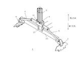
コンテナ用把持装置の全体概要について説明する。図2は、本発明の実施の形態1におけるコンテナ用把持装置の斜視図である。図2は、後述する移動部材3が上部に位置して、コンテナ100を把持する前の状態を示している。
(Overview)
An overall overview of the container gripping device will be described. FIG. 2 is a perspective view of the container gripping device according to the first embodiment of the present invention. FIG. 2 shows a state in which the moving
コンテナ用把持装置1は、支持部材2、移動部材3、第1アーム4、第2アーム5、第1把持部6、第2把持部7を、備える。
The container
支持部材2は、ガイド部材21を備える。支持部材2は、フレーム20と組み合わされており、フレーム20と共にコンテナ用把持装置1の全体の骨格を形成できる。また、支持部材2には、移動部材3、第1アーム4、第2アーム5が取り付けられており、コンテナ用把持装置1の全体の組み合わせの中心となる。
The
移動部材3は、支持部材2に取り付けられる。移動部材3は、この取付けによって、支持部材2に対して移動可能である。移動部材3は、支持部材2に対して、上下方向に昇降する場合もあり、平面方向において平面移動する場合もある。図2では、支持部材2が略垂直方向に設けられているので、これに取り付けられている移動部材3は、上下方向に昇降する。
The moving
移動部材3は、図2に示される矢印の第1方向(図2では下降)と、第2方向(図2では上昇)のそれぞれに移動できる。第1方向と第2方向は、それぞれ逆向きである。
The moving
移動部材3は、ガイド部材21と嵌合する受け部材31を備える。移動部材3が支持部材2に対して(取り付けられている支持部材2において)移動する際には、受け部材31はガイド部材21との嵌合状態を維持する。すなわち、移動部材3は、ガイド部材21に受け部材31を嵌合させたままで、支持部材2に対して移動できる。このため、移動部材3は、支持部材2との組み合わせを無くすことなく移動できる。
The moving
第1アーム4は、移動部材3に取り付けられている。ここで、第1アーム4は、図2に示されるように、移動部材3の一方の側面の位置に取り付けられている。第2アーム5は、移動部材3に取り付けられている。ここで、第2アーム5は、図2に示されるように、移動部材3の他方の側面の位置に取り付けられている。この結果、移動部材3の両側のそれぞれに、第1アーム4と第2アーム5とが取り付けられている。
The first arm 4 is attached to the moving
第1アーム4は、移動部材3にその支点を回動可能に取り付けられている。第2アーム5も、移動部材3に、その支点を回動可能に取り付けられている。このため、移動部材3が移動すると、第1アーム4と第2アーム5との交差角度が変化できる。例えば、移動部材3が第1方向に移動すると、第1アーム4と第2アーム5との交差角度が大きくなる。移動部材3が第2方向に移動すると、第1アーム4と第2アーム5との交差角度が小さくなる。
The first arm 4 is attached to the moving
第1把持部6は、第1アーム4に取り付けられる。第1把持部6は、例えば、第1アーム4の先端に取り付けられる。第1把持部6は、第1アーム4に対して回動可能に取り付けられている。この回動可能な状態によって、第1アーム4が第1方向に移動すると、第1把持部6は、第1アーム4との交差角度を小さくし、第1アーム4が第2方向に移動すると、第1把持部6は、第1アーム4との交差角度を大きくできる。
The
第1把持部6は、コンテナ100の一方の側面に接触する。この接触によって、第1把持部6は、コンテナ100の一方の側面を把持できる。
The
第2把持部7は、第2アーム5に取り付けられる。第2把持部7は、例えば、第2アーム5の先端に取り付けられる。第2把持部7は、第2アーム5に対して回動可能に取り付けられている。この回動可能な状態によって、第2アーム5が第1方向に移動すると、第2把持部7は、第2アーム5との交差角度を小さくし、第2アーム5が第2方向に移動すると、第2把持部7は、第2アーム5との交差角度を大きくできる。
The
第2把持部7は、コンテナ100の一方の側面に接触する。この接触によって、第2把持部7は、コンテナ100の一方の側面を把持できる。このとき、第2把持部7は、第1把持部6と逆側に位置し、コンテナ100において第1把持部6と逆側の側面を把持する。
The
移動部材3は、第1方向および第2方向のそれぞれに移動可能である。ここで、移動部材3が、図2の状態から第1方向に移動して、所定の固定位置に移動した後の状態が図3に示されている。図3は、本発明の実施の形態1における固定位置に移動したコンテナ用把持装置の斜視図である。移動部材3が第1方向に移動して(ここでは、下降して)、所定の固定位置に到達した後の状態を示している。
The moving
移動部材3は、第1方向に沿って移動できる。このとき、支持部材2のガイド部材21に受け部材31が嵌合したままで移動する。移動部材3が第1方向に移動して所定の固定位置に到達する。所定の固定位置とは、第1把持部6と第2把持部7とが、コンテナ100を把持できる位置である。例えば、移動部材3が支持部材2に対して第1方向に移動できる最大の位置である。
The moving
所定の固定位置に移動部材3がある場合には、第1把持部6は、第1アーム4に対して、第1所定角度となる。すなわち、第1把持部6と第1アーム4との交差角度が第1所定角度となる。第1所定角度は、コンテナ100の平面方向に対する側面の角度に略一致する。例えば、コンテナ100が図1のように方形を有する場合には、平面方向に対する側面の角度は略90度である。このため、第1把持部6と第1アーム4との交差角度は、略90度であることが、把持においては好ましい。すなわち、この場合には、第1所定角度は、略90度である。
When the moving
同様に、所定の固定位置に移動部材3がある場合には、第2把持部7は、第2アーム5に対して、第2所定角度となる。すなわち、第2把持部7と第2アーム5との交差角度が第1所定角度となる。第2所定角度は、コンテナ100の平面方向に対する側面の角度に略一致する。例えば、コンテナ100が図1のように方形を有する場合には、平面方向に対する側面の角度は略90度である。このため、第2把持部7と第2アーム5との交差角度は、略90度であることが、把持においては好ましい。すなわち、この場合には、第2所定角度は、略90度である。
Similarly, when the moving
もちろん、コンテナ100の角部の角度によって、第1所定角度と第2所定角度は、様々に設定されればよい。
Of course, the first predetermined angle and the second predetermined angle may be set in various ways depending on the angle of the corner portion of the
ここで、第1把持部6と第1アーム4とは関節で接続されており、関節によって回動可能である。第1アーム4の支点が移動部材3の第1方向の移動によって移動すると、第1アーム4と第1把持部6との交差角度が小さくなっていく。第2把持部7と第2アーム5とも同様である。図3では、第1アーム4と第2アーム5の支点(移動部材3との接続部分)が下がると、第1アーム4と第1把持部6との交差角度が小さくなり、第2アーム5と第2把持部7との交差角度が小さくなる。
Here, the
交差角度が小さくなっていくことで、第1把持部6と第2把持部7は、コンテナ100の両側面に接触できるようになっていく。
As the crossing angle becomes smaller, the
図3は、第1把持部6と第2把持部7のそれぞれは、コンテナ100の両側面を把持できる(両側面に沿って接触して把持できる)状態を示している。移動部材3が固定位置にあることで、第1把持部6と第2把持部7とが、コンテナ100の両側面を把持できるようになる。
FIG. 3 shows a state in which each of the
ここで、第1把持部6と第2把持部7は、移動部材3の位置によって、その位置と角度を固定している。また、移動部材3が、第1把持部6と第2把持部7とに力を付与する。この付与された力で、第1把持部6と第2把持部7は、コンテナ100に把持力を付与して、把持することができる。コンテナ100が重くなっていく場合でも、移動部材3の力のみで、第1把持部6と第2把持部7は、コンテナ100への把持力を強化して、把持できる。
Here, the position and angle of the
図4は、本発明の実施の形態1におけるコンテナ100を把持している状態を示す斜視図である。第1把持部6と第2把持部7のそれぞれが、コンテナ100の両側面を把持している。移動部材3が固定位置にあることで、第1アーム4、第2アーム5の角度も固定され、第1把持部6と第2把持部7のそれぞれが、コンテナ100に把持力を加えている。この把持力によって、第1把持部6と第2把持部7は、確実に、コンテナ100を把持することができる。
FIG. 4 is a perspective view showing a state in which the
なお、コンテナ100の形状によって、第1所定角度と第2所定角度は、略90度以外の角度をもってもよい。
Depending on the shape of the
(動作説明)
次に、コンテナ用把持装置1の動作について説明する。
(Operation explanation)
Next, the operation of the container
図5は、本発明の実施の形態1におけるコンテナの把持を開始するコンテナ用把持装置の正面図である。図6は、本発明の実施の形態1におけるコンテナの把持に近づいたコンテナ用把持装置の正面図である。図7は、本発明の実施の形態1におけるコンテナを把持したコンテナ用把持装置の正面図である。図5〜図7のいずれも、コンテナ用把持装置1とコンテナ100との両方を示している。
FIG. 5 is a front view of a container gripping device that starts gripping a container according to the first embodiment of the present invention. FIG. 6 is a front view of a container gripping device approaching gripping a container according to the first embodiment of the present invention. FIG. 7 is a front view of a container gripping device for gripping a container according to the first embodiment of the present invention. Both FIGS. 5 to 7 show both the container
図5から図7の順序でコンテナ用把持装置1は、コンテナ100の把持を行う。逆に、図7から図5の順序で、コンテナ用把持装置1は、把持していたコンテナ100の開放を行う。
The container
(図5の状態)
まず、コンテナ用把持装置1は、図5の状態となっている。コンテナ100が設置されており、このコンテナ100を把持する準備状態となっている。例えば、コンテナ100が、製造ラインや箱詰めラインに設置されている。コンテナ用把持装置1は、設置されているコンテナ100を把持する位置に設置されている。
(State in FIG. 5)
First, the container
コンテナ用把持装置1において、移動部材3は、支持部材2に対して第1方向への移動を開始する前の状態である。例えば、移動部材3は、第1方向への移動を開始する前の初期状態にある。この初期状態であると、移動部材3に接続されている第1アーム4と第2アーム5とは、その交差角度が最小の状態である。第1アーム4と第2アーム5の支点(移動部材3との接続部分)は、第1方向において移動する前の状態である。図5であれば、これらの支点は、下降前の状態である。
In the container
ただし、支持部材2はフレーム20と共に下に下がっており、第1アーム4などが、コンテナ100を把持できる状態となっている。
However, the
第1アーム4に接続される第1把持部6は、第1アーム4との交差角度が大きな状態である。このため、第1把持部6は、コンテナ100の側面に接触することができていない状態である。
The
同様に、第2アーム5に接続される第2把持部7は、第2アーム5との交差角度が大きな状態である。このため、第2把持部7は、コンテナ100の側面に接触することができない状態である。これらの結果、コンテナ用把持装置1は、まだコンテナ100を把持する前の状態である。
Similarly, the
(図6の状態)
次に、支持部材2に対して移動部材3が第1方向に移動を開始する。図6の状態である。図6では、移動部材3が下降する。移動部材3が第1方向に移動するのに合わせて、第1アーム4と第2アーム5の支点も第1方向に移動する。この移動部材3の移動においては、移動部材3の受け部材31は、支持部材2のガイド部材21と嵌合した状態を維持する。
(State in FIG. 6)
Next, the moving
ここで、ガイド部材21は支持部材2における凹状の凹みであり、受け部材31は、この凹みに嵌合する凸状の凸部であればよい。もちろん、凸凹が逆となって嵌合することでもよい。
Here, the
支点が第1方向に移動することで、第1アーム4と第2アーム5との交差角度も広がっていく。
As the fulcrum moves in the first direction, the crossing angle between the first arm 4 and the
第1アーム4の支点が第1方向に移動すると、第1アーム4と第1把持部6との交差角度が小さくなる。第2アーム5の支点が第1方向に移動すると、第2アーム5と第2把持部7との交差角度が小さくなる。このとき、第1アーム4と第2アーム5とは、移動部材3に同様の位置に接続していることで、第1アーム4と第1把持部6との交差角度の変化と、第2アーム5と第2把持部7との交差角度の変化は同様になる。もちろん、異なるように構成されていてもよい。
When the fulcrum of the first arm 4 moves in the first direction, the crossing angle between the first arm 4 and the
移動部材3が第1方向に移動を進めるにつれて、第1アーム4と第1把持部6との交差角度は小さくなっていく。この交差角度が小さくなっていくことに伴って、第1把持部6の内側がコンテナ100の側面に近づいていく。同様に、移動部材3が第1方向に移動を進めるにつれて、第2アーム5と第2把持部7との交差角度は小さくなっていく。この交差角度が小さくなっていくことに伴って、第2把持部7の内側がコンテナ100の側面に近づいていく。
As the moving
第1把持部6および第2把持部7のそれぞれの内側が、コンテナ100の側面に接触する。
The inside of each of the
(図7の状態)
図7は、移動部材3が固定位置に到達した状態を示している。移動部材3が第1方向に移動して、所定の固定位置に到達する。所定の固定位置は、第1把持部6と第2把持部7とがコンテナ100を把持できる状態となる位置である。固定位置は、コンテナ100の形状、コンテナ用把持装置1の構成などによって定められれば良い。例えば、第1アーム4と第2アーム5との交差角度が略180度、すなわち、これらが略平行となる状態であればよい。
(State in Fig. 7)
FIG. 7 shows a state in which the moving
移動部材が固定位置に近づくにつれて、第1アーム4と第1把持部6との交差角度が縮小して第1所定角度に近づいていく。更に、移動部材3が固定位置に到達すると、図7に示されるように、第1アーム4と第1把持部6との交差角度が第1所定角度となる。
As the moving member approaches the fixed position, the crossing angle between the first arm 4 and the
同様に、移動部材が固定位置に近づくにつれて、第2アーム5と第2把持部7との交差角度が縮小して第2所定角度に近づいていく。更に、移動部材3が固定位置に到達すると、図7に示されるように、第2アーム5と第2把持部7との交差角度が第2所定角度となる。
Similarly, as the moving member approaches the fixed position, the crossing angle between the
図7は、第1所定角度および第2所定角度となって、第1把持部6と第2把持部7とが、コンテナ100の両側面を把持している状態を示している。
FIG. 7 shows a state in which the
第1所定角度は、コンテナ100の平面方向に対する側面の角度に略一致し、第2所定角度も同様である。このような角度となることで、第1把持部6の内側と第2把持部7の内側は、コンテナ100の両側面のそれぞれに接触する状態となる。
The first predetermined angle substantially coincides with the angle of the side surface of the
ここで、第1アーム4と第2アーム5とが開いた長さは、コンテナ100の両側面同士の距離(長さ)に一致する。すなわち、第1把持部6と第2把持部7との間隔は、コンテナ100の長さに一致する。この一致によって、第1把持部6と第2把持部7との内側のそれぞれは、コンテナ100の両側面のそれぞれに接触しつつ把持力を付与することができる。
Here, the length at which the first arm 4 and the
固定位置にあるとき、移動部材3はガイド部材21と受け部材31との嵌合によって、支持部材2に対して、その固定位置を維持できる。すなわち、位置を固定できる。移動部材3が、固定位置に固定できることで、第1アーム4、第2アーム5、第1把持部6、第2把持部7のそれぞれの位置関係、相互の角度関係、構成を維持できる。
When in the fixed position, the moving
この結果、移動部材3は、第1アーム4を介して第1把持部6に把持力を付与できる。移動部材3は、第2アーム5を介して、第2把持部7に把持力を付与できる。第1把持部6と第2把持部7のそれぞれは、コンテナ100の両側面に接触して、移動部材3から付与される把持力をコンテナ100に与えて、把持できる。
As a result, the moving
移動部材3が、第1方向に移動することにより固定位置に移動する。固定位置で、移動部材3は、固定できる。このとき、ガイド部材21と受け部材31との嵌合によって、固定位置において、移動部材3は、位置が固定される。併せて、第1アーム4と第2アーム5の位置が固定される。
The moving
すなわち、コンテナ用把持装置1は、上下方向の移動力に独立した左右からの把持力の付与機構を必要としない。
That is, the container
図7の状態のままで、支持部材2が、上昇すれば第1把持部6と第2把持部7とによって把持されているコンテナ100が持ち上がる(上昇する)。支持部材2が平面方向に移動すれば、第1把持部6と第2把持部7とによって把持されているコンテナ100は、平面方向に移動する(3次元方向の移動も同じ)。
If the
このとき、移動部材3は支持部材2に対して、ガイド部材21と受け部材31との嵌合によって、その位置が固定位置に固定されている。平面方向や上下方向などに、移動部材3の支持部材2に対する位置が変動することはない。第1把持部6は、第1アーム4を介して移動部材3に連結している。第1アーム4の長さは変化しないので、第1把持部6の移動部材3に対する位置も、変化しない。同様に、第2把持部7は、第2アーム5を介して移動部材3に連結している。第2アーム5の長さは変化しないので、第2把持部7の移動部材3に対する位置も、変化しない。
At this time, the position of the moving
すなわち、移動部材3が固定位置に固定されている状態では、第1把持部6と第2把持部7との相対的な位置関係が変化しない。すなわち、コンテナ100が第1把持部6と第2把持部7との間で動かない。すなわち、支持部材2の移動によって、コンテナ100が平面方向に揺れない。この結果、把持における平面方向への把持力の増加の必要性を抑えることができる。
That is, in the state where the moving
また、第1把持部6と第2把持部7とは、支持部材2に対する移動部材3の固定のみで、その把持力を生じさせる。コンテナ100との位置関係と対応関係が、移動部材3の固定に依るからである。すなわち、把持に必要な力は、移動部材3の固定力のみで済む。結果として、力の付与における機構の複雑性が少なくなり、コンテナ100の揺れ、コンテナ100の把持のために、把持部の機構の大型化などの従来技術の問題点を解決できる。
Further, the
(移動部材の固定位置での相対関係)
図7を用いて上述したように、移動部材3は、支持部材2に対して第1方向(図7では、下降方向)に移動して、固定位置に到達する。移動部材3の第1方向に移動させる駆動機構が移動力を付与し続けている限り、ガイド部材21と受け部材31との嵌合によって、移動部材3は固定位置で固定される。
(Relative relationship at fixed position of moving member)
As described above with reference to FIG. 7, the moving
この固定位置にある場合は、第1アーム4と第1把持部6とは、第1所定角度の交差角度を維持できる。同様に、第2アーム5と第2把持部7とは、第2所定角度の交差角度を維持できる。第1所定角度および第2所定角度は、上述したように、コンテナ100の両側面を把持できる角度である。
When in this fixed position, the first arm 4 and the
また、移動部材3を基準として、第1把持部6までの距離と、第2把持部7までの距離も維持できる。この距離によって、コンテナ100の幅に合った把持ができる。これらの角度および距離が一定であることで、把持されたコンテナ100が、平面方向(水平方向)に揺れることが無い(移動部材3を基準として)。
Further, the distance to the
このとき、コンテナ100の両側面となる角部の角度が略90度である場合には、第1所定角度および第2所定角度のそれぞれは、略90度であることが好ましい。もちろん、コンテナ100の両側面となる角部の角度が、他の角度である場合には、第1所定角度および第2所定角度のそれぞれは、この他の角度であればよい。
At this time, when the angles of the corners on both sides of the
このように、移動部材3を基準とした、第1把持部6と第2把持部7までの距離(相対的な位置関係)が一定であると共に、第1所定角度と第2所定角度での維持がなされることで、コンテナ100が第1把持部6と第2把持部7との間で揺れて運搬されることが無くなる。
In this way, the distance (relative positional relationship) between the
また、第1把持部6と第2把持部7は、移動部材3の固定位置での固定によって、その角度を固定して、相対距離を固定できる。これら2つが固定されることで、第1把持部6と第2把持部7とは、コンテナ100に対して把持力を付与することができる。すなわち、第1把持部6と第2把持部7は、移動部材3が固定される力のみで(移動部材3を第1方向に移動させて固定位置に維持させる駆動機構の駆動力)、コンテナ100の把持力を生じさせる。この把持力で、第1把持部6と第2把持部7とは、コンテナ100を把持できる。
Further, the angle of the
また、移動部材3が固定位置にある場合には、第1アーム4と第2アーム5とは、略平行となる。略平行となることで、コンテナ100を把持している際の、把持力の付与が、効率的に行える。また、把持力を高めることもできる。特に、第1所定角度および第2所定角度が略90度である場合には、移動部材3の固定力のみで把持力を生じさせる場合の把持力を大きくできる。
Further, when the moving
以上のように、実施の形態1におけるコンテナ用把持装置1は、従来技術の問題点を解決して、コンテナ100の大型化にも対応して、コンテナ100を確実に把持できる。
As described above, the container
(実施の形態2) (Embodiment 2)
次に、実施の形態2について説明する。 Next, the second embodiment will be described.
(ピストンによる移動部材の移動)
図8は、本発明の実施の形態2におけるコンテナ用把持装置の斜視図である。コンテナ用把持装置1の移動部材3の部分にフォーカスした状態を示している。図3などと同じ要素については、符号を省略している。
(Movement of moving member by piston)
FIG. 8 is a perspective view of the container gripping device according to the second embodiment of the present invention. It shows a state in which the moving
移動部材3は、位置決め部材32とピストン34を、有する。位置決め部材32は、ガイド部材21と受け部材31との嵌合をもって移動する部材である。この移動によって、移動部材3の位置、すなわち、第1アーム4と第2アーム5の位置を決める。
The moving
ピストン33は、位置決め部材32を移動させる。このとき、第1方向および第2方向に、ピストン33は、位置決め部材32を移動させる。ピストン33は、空気圧、油圧など種々の圧力駆動を受けて移動すればよい。位置決め部材32がピストン33によって移動させられることで、移動部材3は、固定位置での固定が可能となる。固定位置となるようにピストン33が移動して、ピストン33に付与される圧力が継続されれば移動部材3は、固定位置で固定されたままとなる。
The
ピストン33が第1方向に移動すれば、位置決め部材32も第1方向に移動する。ピストン33が第2方向に移動すれば、位置決め部材32も第2方向に移動する。ピストン33に空気圧や油圧などの圧力が加わっているので、位置決め部材33は、その位置を固定できる。
If the
ピストン33によって位置決め部材32が移動されて位置を変化させることで、移動部材3の位置変化や位置固定を精度よく行える。また、位置の固定も容易となる。位置固定を行う力は、このピストン33の力であるので、固定位置への固定も確実にできる。なお、ピストン33は、モーターによって移動が実現されてもよい。
By moving the positioning
(アームの長さの可変)
第1アーム4と第2アーム5のそれぞれの長さが可変であることも好適である。第1アーム4と第2アーム5の長さは、コンテナ100の幅に対応する。コンテナ100は、規格によりその幅が一定であることが多いが、種類や製造者が変わることで、その幅も変化することがある。
(Variable arm length)
It is also preferable that the lengths of the first arm 4 and the
第1アーム4と第2アーム5のそれぞれの長さが可変であることで、このコンテナ100の幅の変化に対応できる。例えば、第1アーム4と第2アーム5が折り畳み式であることで長さを可変としてもよい。あるいは、第1アーム4と第2アーム5とが、伸縮式であることで、長さを可変としてもよい。あるいは、第1アーム4と第2アーム5とが、継ぎ足し構造であることで、長さを可変とすることでもよい。
Since the lengths of the first arm 4 and the
あるいは、第1アーム4と第2アーム5とが取り換え可能であることで、長さを可変とすることでもよい。
Alternatively, the length may be variable because the first arm 4 and the
このように、第1アーム4と第2アーム5の長さが可変であることで、様々な大きさのコンテナ100の把持に対応できる。
As described above, since the lengths of the first arm 4 and the
(ガイド部材)
ガイド部材21は、受け部材31と嵌合する。この嵌合によって、支持部材2と移動部材3との相対的な位置関係が維持される。また、固定位置での固定も維持される。
(Guide member)
The
このとき、ガイド部材21が凹状であって受け部材が凸状の場合には、ガイド部材21の下方における幅が上方における幅よりも小さいことも好適である。図9は、本発明の実施の形態2における支持部材の正面図である。支持部材2に、凹状のガイド部材21が設けられている。
At this time, when the
図9のように、ガイド部材21の下方における幅は、上方における幅よりも小さい。この凹状のガイド部材21に、凸状の受け部材31が嵌合する。この時、下方に下がるにしたがって、ガイド部材21と受け部材31との嵌合は強固になる。特に、幅方向における隙間が減少することで、幅方向での固定と嵌合が強固になる。
As shown in FIG. 9, the width below the
結果として、固定位置(下方にある)においては、嵌合する受け部材31は、幅方向に位置変化しにくい。固定位置では、第1把持部6と第2把持部7が、コンテナ100を把持している。この把持状態にあるときに、嵌合状態が強く、幅方向に動きにくいので、コンテナ100の把持での揺れを更に防止できる。
As a result, in the fixed position (below), the
加えて、上方では、幅が広いので、第1方向への移動においてスムーズであり、ガイド部材21や受け部材31の損耗を軽減できる。
In addition, since the width is wide above, the movement in the first direction is smooth, and the wear of the
言い換えれば、固定位置におけるガイド部材21の幅は、それ以外での幅よりも小さいことになる。
In other words, the width of the
逆に、ガイド部材21が凸状であり受け部材31が凹状の場合には、幅の変化は逆となる。ガイド部材21の固定位置における幅は、それ以外での幅よりも小さい。
On the contrary, when the
あるいは、受け部材31が、上記のガイド部材21のように幅変化をもっていることでもよい。
Alternatively, the receiving
(第1把持部と第2把持部)
図10は、本発明の実施の形態2におけるコンテナ用把持装置の斜視図である。
(1st grip and 2nd grip)
FIG. 10 is a perspective view of the container gripping device according to the second embodiment of the present invention.
第1把持部6は、第1サブアーム61と第1把持爪62を有する。第1サブアーム61は、第1アーム4と回動可能に接続されている。第1把持爪62は、第1サブアーム61と回動可能に接続される。すなわち、第1アーム4を基準として、第1把持爪62は、2段階で角度を変化させる。
The
第1把持爪62が、コンテナ100の側面に接触して把持するので、2段階の回動で角度変化することで、第1所定角度を、精度よく実現できる。第1把持爪62には、突起63が備わっていることも、把持力を上げる点で好適である。
Since the first
第2把持部7は、第2サブアーム71と第2把持爪72を有する。第2サブアーム71は、第2アーム5と回動可能に接続されている。第2把持爪72は、第2サブアーム71と回動可能に接続される。すなわち、第2アーム5を基準として、第2把持爪72は、2段階で角度を変化させる。
The
第2把持爪72が、コンテナ100の側面に接触して把持するので、2段階の回動で角度変化することで、第2所定角度を、精度よく実現できる。第2把持爪72には、突起73が備わっていることも、把持力を上げる点で好適である。
Since the second
(移動部材と支持部材の向き)
図3などを用いた説明では、支持部材2および移動部材3が垂直方向である場合を例として説明した。このため、第1方向は下降方向であり、第2方向は上昇方向である。この昇降によって、第1把持部6と第2把持部7とが、コンテナ100の両側面を把持することができる構成となっている。
(Orientation of moving member and support member)
In the description using FIG. 3 and the like, the case where the
この昇降でのコンテナ100の把持は、コンテナ100が床面などに置かれており、上からコンテナ用把持装置1が、コンテナ100を把持しようとする態様に対応している。
The gripping of the
これに対して、コンテナ100の横から把持を行うことが必要なこともある。コンテナ用把持装置1は、コンテナ100を移動させるために用いられる。この移動に係る駆動装置の設置場所や移動場所の態様によっては、コンテナ100を、横から把持することがベターであることもある。
On the other hand, it may be necessary to grip the
この場合には、図3などで示されるコンテナ用把持装置が、平面方向に沿って設置されたり、斜め方向に沿って設置されたりすればよい。この場合には、支持部材2とこれに組み合わさる移動部材3とが、平面方向に沿っていたり、斜め方向に沿っていたりすればよい(勿論、種々の角度に沿っていればよい)。
In this case, the container gripping device shown in FIG. 3 or the like may be installed along the plane direction or along the diagonal direction. In this case, the
このような種々の角度で支持部材2と移動部材3とが設置されている構成の場合には、移動部材3は、この種々の角度に基づいて、支持部材2に対して移動できる。この移動によっても、第1把持部6と第2把持部7とは、それぞれの交差角度を第1所定角度および第2所定角度にすることができる。このとき、第1把持部6と第2把持部7の把持面は、コンテナ100の横から側面を挟むことができたり、他の角度から側面を挟んだりすることができる。
In the case where the
また、支持部材2および移動部材3は、略平面(水平)方向に移動する角度で設置されており、第1アーム4と第2アーム5とが略垂直方向にその角度を変える構造でもよい。
Further, the
(2個のコンテナの把持)
図11は、本発明の実施の形態2における複数コンテナを把持できるコンテナ用把持装置の斜視図である。図11に示されるコンテナ用把持装置1は、2個のコンテナ100を同時に把持できる構成を有している。フレーム11に2つのコンテナ用把持装置の各要素が組み合わされている。
(Gripping two containers)
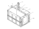
FIG. 11 is a perspective view of a container gripping device capable of gripping a plurality of containers according to the second embodiment of the present invention. The container
この組み合わせによって、同時に2個のコンテナ100を把持可能である。なお、図11では、見易さのために、1個のコンテナ100のみが把持されている状態が示されている。
With this combination, it is possible to grip two
2つのコンテナ用把持装置1の要素が組み合わされている。このため、支持部材2A、支持部材2B、移動部材3A、移動部材3B、第1把持部6A、第1把持部6B、第2把持部7A、第2把持部7Bのそれぞれが備わっている。
The elements of the two
第1把持部6Aと第2把持部7Aとが、一つのコンテナ100を把持する。第1把持部6Bと第2把持部7Bとが、一つのコンテナ100を把持する。このように、それぞれがコンテナ100を把持することができるので、2個のコンテナ100を同時に把持したり移動させたりすることができる。
The
もちろん、2個に限られるものではなく、把持装置1の組み合わせ数を上げることで、3個以上のコンテナ100を同時把持することもできる。
Of course, the number is not limited to two, and by increasing the number of combinations of the
このような構成を有することで、コンテナ100の把持とこれに伴う移動における効率化を図ることができる。
By having such a configuration, it is possible to improve the efficiency in gripping the
なお、実施の形態1〜2で説明されたコンテナ用把持装置は、本発明の趣旨を説明する一例であり、本発明の趣旨を逸脱しない範囲での変形や改造を含む。 The container gripping device described in the first and second embodiments is an example for explaining the gist of the present invention, and includes deformation and modification within a range not deviating from the gist of the present invention.
1 コンテナ用把持装置
11 フレーム
2 支持部材
20 フレーム
21 ガイド部材
3 移動部材
31 受け部材
32 位置決め部材
33 ピストン
4 第1アーム
5 第2アーム
6 第1把持部
61 第1サブアーム
62 第1把持爪
63 突起
7 第2把持部
71 第2サブアーム
72 第2把持爪
73 突起
100 コンテナ
1 Grip device for
Claims (15)
ガイド部材を有する支持部材と、
前記支持部材に取り付けられて、該支持部材に対して移動可能な移動部材と、
前記移動部材の一方の側面に取り付けられた第1アームと、
前記移動部材において、前記第1アームと逆側に取り付けられた第2アームと、
前記第1アームの先端に取り付けられた第1把持部と、
前記第2アームの先端に取り付けられた第2把持部と、を備え、
前記移動部材は、前記ガイド部材と嵌合する受け部材を有し、前記移動部材が前記支持部材に対して移動する際に、前記ガイド部材と前記受け部材とは嵌合状態を維持し、
前記移動部材が所定の固定位置にある場合には、前記第1把持部は前記第1アームに対して第1所定角度となり、前記第2把持部は前記第2アームに対して第2所定角度となり、
前記第1所定角度および前記第2所定角度のそれぞれは、前記コンテナの平面方向に対する側面の角度に略一致し、前記第1把持部および前記第2把持部のそれぞれは、前記コンテナの両側面を把持でき、
前記移動部材は、第1方向に移動することで前記固定位置に移動し、
前記移動部材は、
前記ガイド部材と前記受け部材との嵌合をもって移動する位置決め部材と、
前記位置決め部材の移動を行うピストンと、
を、有し、
前記ピストンの前記第1方向への移動によって前記位置決め部材が前記第1方向に移動し、前記固定位置において、前記位置決め部材が固定された状態を維持できる、コンテナ用把持装置。 A container gripping device that grips a container.
A support member with a guide member and
A moving member attached to the support member and movable with respect to the support member,
A first arm attached to one side surface of the moving member,
In the moving member, the second arm attached to the opposite side of the first arm and
The first grip portion attached to the tip of the first arm and
A second grip portion attached to the tip of the second arm is provided.
The moving member has a receiving member that fits with the guide member, and when the moving member moves with respect to the support member, the guide member and the receiving member maintain a fitted state.
When the moving member is in a predetermined fixed position, the first grip portion has a first predetermined angle with respect to the first arm, and the second grip portion has a second predetermined angle with respect to the second arm. Next,
Each of the first predetermined angle and the second predetermined angle substantially coincides with the angle of the side surface of the container with respect to the plane direction, and each of the first grip portion and the second grip portion holds both side surfaces of the container. Can be grasped,
The moving member moves to the fixed position by moving in the first direction.
The moving member is
A positioning member that moves by fitting the guide member and the receiving member, and
The piston that moves the positioning member and
Have,
A gripping device for a container capable of moving the positioning member in the first direction by moving the piston in the first direction and maintaining the positioning member fixed at the fixed position.
前記第1把持部および前記第2把持部のそれぞれは、前記コンテナの両側面に接触して、前記移動部材から付与される力を前記コンテナに与えて把持する、請求項1記載のコンテナ用把持装置。 The moving member applies a force to the first grip portion via the first arm, and applies a force to the second grip portion via the second arm.
The container grip according to claim 1, wherein each of the first grip portion and the second grip portion contacts both side surfaces of the container and applies a force applied from the moving member to the container to grip the container. Device.
前記第2アームが前記第1方向に移動するに従い、前記第2アームと前記第2把持部との交差角度は縮小して、前記第2所定角度に近づく、請求項4記載のコンテナ用把持装置。 As the first arm moves in the first direction, the crossing angle between the first arm and the first grip portion decreases and approaches the first predetermined angle.
The gripping device for a container according to claim 4, wherein as the second arm moves in the first direction, the crossing angle between the second arm and the second gripping portion is reduced and approaches the second predetermined angle. ..
前記第1アームと前記第1把持部とは、前記第1所定角度の交差角度を維持でき、
前記第2アームと前記第2把持部とは、前記第2所定角度の交差角度を維持でき、
前記移動部材を基準として、前記第1把持部までの距離と前記第2把持部までの距離が維持される、請求項1から5のいずれか記載のコンテナ用把持装置。 When the moving member is in the fixed position,
The first arm and the first grip portion can maintain the intersection angle of the first predetermined angle.
The second arm and the second grip portion can maintain the intersection angle of the second predetermined angle.
The gripping device for a container according to any one of claims 1 to 5 , wherein the distance to the first gripping portion and the distance to the second gripping portion are maintained with the moving member as a reference.
前記第2把持部は、前記第2アームと回動可能に接続される第2サブアームと、当該第2サブアームと回動可能に接続される第2把持爪と、を有する、請求項1から12のいずれか記載のコンテナ用把持装置。 The first grip portion has a first sub-arm rotatably connected to the first arm and a first grip claw rotatably connected to the first sub-arm.
The second grip portion has a second sub-arm rotatably connected to the second arm and a second grip claw rotatably connected to the second sub-arm, according to claims 1 to 12. The gripping device for a container according to any one of the above.
前記第1アームおよび前記第2アームは、略垂直方向において、その交差角度を変化させる、請求項1から14のいずれか記載のコンテナ用把持装置。
The moving member moves substantially horizontally based on the installation angle of the supporting member.
The container gripping device according to any one of claims 1 to 14 , wherein the first arm and the second arm change their crossing angles in a substantially vertical direction.
Priority Applications (1)
| Application Number | Priority Date | Filing Date | Title |
|---|---|---|---|
| JP2017144065A JP6976096B2 (en) | 2017-07-26 | 2017-07-26 | Container gripping device |
Applications Claiming Priority (1)
| Application Number | Priority Date | Filing Date | Title |
|---|---|---|---|
| JP2017144065A JP6976096B2 (en) | 2017-07-26 | 2017-07-26 | Container gripping device |
Publications (2)
| Publication Number | Publication Date |
|---|---|
| JP2019026394A JP2019026394A (en) | 2019-02-21 |
| JP6976096B2 true JP6976096B2 (en) | 2021-12-08 |
Family
ID=65475597
Family Applications (1)
| Application Number | Title | Priority Date | Filing Date |
|---|---|---|---|
| JP2017144065A Active JP6976096B2 (en) | 2017-07-26 | 2017-07-26 | Container gripping device |
Country Status (1)
| Country | Link |
|---|---|
| JP (1) | JP6976096B2 (en) |
Families Citing this family (2)
| Publication number | Priority date | Publication date | Assignee | Title |
|---|---|---|---|---|
| JP7319668B2 (en) * | 2019-10-29 | 2023-08-02 | 株式会社ナベル | Container transfer device |
| KR102533554B1 (en) * | 2022-10-31 | 2023-05-16 | (주)대우건설 | Grip module for steel mold transport and placement |
-
2017
- 2017-07-26 JP JP2017144065A patent/JP6976096B2/en active Active
Also Published As
| Publication number | Publication date |
|---|---|
| JP2019026394A (en) | 2019-02-21 |
Similar Documents
| Publication | Publication Date | Title |
|---|---|---|
| US8240973B2 (en) | Palletizing robot | |
| JP7186546B2 (en) | Transfer device | |
| US20170050314A1 (en) | Industrial robot | |
| KR102137192B1 (en) | Food input device | |
| KR20110039455A (en) | Apparatus and method for transferring board-like work | |
| US11702297B2 (en) | Transfer method to drag grip target object | |
| JP6976096B2 (en) | Container gripping device | |
| JP2017052052A (en) | Cargo handling gear and cargo handling method | |
| WO2018066642A1 (en) | Food item holding device | |
| WO2018155690A1 (en) | Boxing device and boxing method | |
| KR20210091239A (en) | Goods transport equipment | |
| JP2019210038A (en) | Box assembly and packaging system and controller for system | |
| US20050220599A1 (en) | Clamshell and fork-style material handling apparatus | |
| KR101480346B1 (en) | gravity compensation device of vertical articulated robot with a parallel link structure | |
| KR20200114567A (en) | Apparatus for Aligning Panel like Items | |
| JPS61257829A (en) | Robot system for article palletizing | |
| US20230109294A1 (en) | Robot carriage tray table | |
| CN113165171A (en) | Robotic system including articulated arm | |
| JP6738302B2 (en) | Food holding device | |
| TW202332554A (en) | Multi-mode robotic end effector | |
| CN206544181U (en) | Facility for the control coordinated with each other of at least two parallel kinematical machinery hands | |
| JP6894745B2 (en) | Food holding device and its operation method | |
| JP6157127B2 (en) | Article moving device | |
| JP6056707B2 (en) | Article transfer device and transfer equipment | |
| JPH085961Y2 (en) | Robot system for article palletizing |
Legal Events
| Date | Code | Title | Description |
|---|---|---|---|
| A621 | Written request for application examination |
Free format text: JAPANESE INTERMEDIATE CODE: A621 Effective date: 20200414 |
|
| A977 | Report on retrieval |
Free format text: JAPANESE INTERMEDIATE CODE: A971007 Effective date: 20210219 |
|
| A131 | Notification of reasons for refusal |
Free format text: JAPANESE INTERMEDIATE CODE: A131 Effective date: 20210330 |
|
| A521 | Written amendment |
Free format text: JAPANESE INTERMEDIATE CODE: A523 Effective date: 20210407 |
|
| TRDD | Decision of grant or rejection written | ||
| A01 | Written decision to grant a patent or to grant a registration (utility model) |
Free format text: JAPANESE INTERMEDIATE CODE: A01 Effective date: 20211102 |
|
| A61 | First payment of annual fees (during grant procedure) |
Free format text: JAPANESE INTERMEDIATE CODE: A61 Effective date: 20211109 |
|
| R150 | Certificate of patent or registration of utility model |
Ref document number: 6976096 Country of ref document: JP Free format text: JAPANESE INTERMEDIATE CODE: R150 |