EP3138633B1 - Programmierbarer konzentrischer kopf zum auftragen von flüssigkeiten auf deckel verschiedener form - Google Patents
Programmierbarer konzentrischer kopf zum auftragen von flüssigkeiten auf deckel verschiedener form Download PDFInfo
- Publication number
- EP3138633B1 EP3138633B1 EP14890782.7A EP14890782A EP3138633B1 EP 3138633 B1 EP3138633 B1 EP 3138633B1 EP 14890782 A EP14890782 A EP 14890782A EP 3138633 B1 EP3138633 B1 EP 3138633B1
- Authority
- EP
- European Patent Office
- Prior art keywords
- liquid
- shaft
- application
- lids
- onto
- Prior art date
- Legal status (The legal status is an assumption and is not a legal conclusion. Google has not performed a legal analysis and makes no representation as to the accuracy of the status listed.)
- Active
Links
Images


Classifications
-
- B—PERFORMING OPERATIONS; TRANSPORTING
- B05—SPRAYING OR ATOMISING IN GENERAL; APPLYING FLUENT MATERIALS TO SURFACES, IN GENERAL
- B05B—SPRAYING APPARATUS; ATOMISING APPARATUS; NOZZLES
- B05B13/00—Machines or plants for applying liquids or other fluent materials to surfaces of objects or other work by spraying, not covered by groups B05B1/00 - B05B11/00
- B05B13/02—Means for supporting work; Arrangement or mounting of spray heads; Adaptation or arrangement of means for feeding work
- B05B13/04—Means for supporting work; Arrangement or mounting of spray heads; Adaptation or arrangement of means for feeding work the spray heads being moved during spraying operation
-
- B—PERFORMING OPERATIONS; TRANSPORTING
- B05—SPRAYING OR ATOMISING IN GENERAL; APPLYING FLUENT MATERIALS TO SURFACES, IN GENERAL
- B05B—SPRAYING APPARATUS; ATOMISING APPARATUS; NOZZLES
- B05B13/00—Machines or plants for applying liquids or other fluent materials to surfaces of objects or other work by spraying, not covered by groups B05B1/00 - B05B11/00
- B05B13/02—Means for supporting work; Arrangement or mounting of spray heads; Adaptation or arrangement of means for feeding work
- B05B13/0278—Arrangement or mounting of spray heads
-
- B—PERFORMING OPERATIONS; TRANSPORTING
- B05—SPRAYING OR ATOMISING IN GENERAL; APPLYING FLUENT MATERIALS TO SURFACES, IN GENERAL
- B05B—SPRAYING APPARATUS; ATOMISING APPARATUS; NOZZLES
- B05B13/00—Machines or plants for applying liquids or other fluent materials to surfaces of objects or other work by spraying, not covered by groups B05B1/00 - B05B11/00
- B05B13/02—Means for supporting work; Arrangement or mounting of spray heads; Adaptation or arrangement of means for feeding work
- B05B13/04—Means for supporting work; Arrangement or mounting of spray heads; Adaptation or arrangement of means for feeding work the spray heads being moved during spraying operation
- B05B13/0463—Installation or apparatus for applying liquid or other fluent material to moving work of indefinite length
- B05B13/0468—Installation or apparatus for applying liquid or other fluent material to moving work of indefinite length with reciprocating or oscillating spray heads
-
- B—PERFORMING OPERATIONS; TRANSPORTING
- B05—SPRAYING OR ATOMISING IN GENERAL; APPLYING FLUENT MATERIALS TO SURFACES, IN GENERAL
- B05B—SPRAYING APPARATUS; ATOMISING APPARATUS; NOZZLES
- B05B13/00—Machines or plants for applying liquids or other fluent materials to surfaces of objects or other work by spraying, not covered by groups B05B1/00 - B05B11/00
- B05B13/02—Means for supporting work; Arrangement or mounting of spray heads; Adaptation or arrangement of means for feeding work
- B05B13/04—Means for supporting work; Arrangement or mounting of spray heads; Adaptation or arrangement of means for feeding work the spray heads being moved during spraying operation
- B05B13/0463—Installation or apparatus for applying liquid or other fluent material to moving work of indefinite length
- B05B13/0484—Installation or apparatus for applying liquid or other fluent material to moving work of indefinite length with spray heads having a circular motion, e.g. being attached to a rotating supporting element
-
- B—PERFORMING OPERATIONS; TRANSPORTING
- B05—SPRAYING OR ATOMISING IN GENERAL; APPLYING FLUENT MATERIALS TO SURFACES, IN GENERAL
- B05B—SPRAYING APPARATUS; ATOMISING APPARATUS; NOZZLES
- B05B14/00—Arrangements for collecting, re-using or eliminating excess spraying material
- B05B14/40—Arrangements for collecting, re-using or eliminating excess spraying material for use in spray booths
- B05B14/44—Arrangements for collecting, re-using or eliminating excess spraying material for use in spray booths using walls specially adapted for promoting separation of the excess material from the air, e.g. baffle plates
-
- B—PERFORMING OPERATIONS; TRANSPORTING
- B05—SPRAYING OR ATOMISING IN GENERAL; APPLYING FLUENT MATERIALS TO SURFACES, IN GENERAL
- B05B—SPRAYING APPARATUS; ATOMISING APPARATUS; NOZZLES
- B05B7/00—Spraying apparatus for discharge of liquids or other fluent materials from two or more sources, e.g. of liquid and air, of powder and gas
- B05B7/02—Spray pistols; Apparatus for discharge
-
- B—PERFORMING OPERATIONS; TRANSPORTING
- B05—SPRAYING OR ATOMISING IN GENERAL; APPLYING FLUENT MATERIALS TO SURFACES, IN GENERAL
- B05C—APPARATUS FOR APPLYING FLUENT MATERIALS TO SURFACES, IN GENERAL
- B05C13/00—Means for manipulating or holding work, e.g. for separate articles
- B05C13/02—Means for manipulating or holding work, e.g. for separate articles for particular articles
-
- B—PERFORMING OPERATIONS; TRANSPORTING
- B05—SPRAYING OR ATOMISING IN GENERAL; APPLYING FLUENT MATERIALS TO SURFACES, IN GENERAL
- B05C—APPARATUS FOR APPLYING FLUENT MATERIALS TO SURFACES, IN GENERAL
- B05C5/00—Apparatus in which liquid or other fluent material is projected, poured or allowed to flow on to the surface of the work
- B05C5/02—Apparatus in which liquid or other fluent material is projected, poured or allowed to flow on to the surface of the work the liquid or other fluent material being discharged through an outlet orifice by pressure, e.g. from an outlet device in contact or almost in contact, with the work
- B05C5/0208—Apparatus in which liquid or other fluent material is projected, poured or allowed to flow on to the surface of the work the liquid or other fluent material being discharged through an outlet orifice by pressure, e.g. from an outlet device in contact or almost in contact, with the work for applying liquid or other fluent material to separate articles
-
- B—PERFORMING OPERATIONS; TRANSPORTING
- B21—MECHANICAL METAL-WORKING WITHOUT ESSENTIALLY REMOVING MATERIAL; PUNCHING METAL
- B21D—WORKING OR PROCESSING OF SHEET METAL OR METAL TUBES, RODS OR PROFILES WITHOUT ESSENTIALLY REMOVING MATERIAL; PUNCHING METAL
- B21D51/00—Making hollow objects
- B21D51/16—Making hollow objects characterised by the use of the objects
- B21D51/38—Making inlet or outlet arrangements of cans, tins, baths, bottles, or other vessels; Making can ends; Making closures
- B21D51/44—Making closures, e.g. caps
- B21D51/46—Placing sealings or sealing material
Definitions
- the present invention relates to a programmable concentric head for the application of liquid to lids of different shapes, which includes mainly circular-shaped lids and of certain shape, and that performs the application with all types of lid geometries. Since among all of the functionalities provided by the head, the application of liquids to lids is one of the most required, this will be the one described in the present invention without thereby excluding the rest of the applications mentioned below.
- the programmable concentric head for the application of liquid to lids of different shapes is capable of applying liquid material in lids of circular geometries and of certain shapes: square, rectangular and oval, among others, and it applies it with formats with a diagonal ranging between 62 mm and 314 mm, which includes almost all the lids available in the market, at a maximum speed of 250 lids per minute.
- the concentric head of the invention is provided in a single unit, is highly durable, requires minimum space, is extremely productive, requires minimum maintenance, is capable of simply and easily exchanging different lid formats, is easily adapted to machines owned by the proprietor of the invention in question, and even to machines made by other manufacturers, is capable of sealing/repairing circular lids and of certain shapes at least with an injecting pistol for application within the vast range of previously mentioned sizes and which may supply substantially all types of lids currently available in the market and is capable of performing different functions, such as rubberising/varnishing, as well as those analogous to a pantograph or plotter to make strokes and/or sign-writing, given its multi-purpose nature and versatile design.
- Spanish patent applications P 201031569 and P 201031868 are known in the art, both owned by the proprietor of the present invention and both of which refer to heads for re-varnishing lids.
- the programmable concentric head for application to lids of different shapes which is the object of the invention, is intended for applying a liquid fluid to a peripheral area of a lid by means of pistols for injecting said liquid substance, wherein said injecting pistols are related to movable mechanisms that drag the injecting pistols through said peripheral area of the lid, wherein said movable mechanisms are included in a device for applying liquids supported onto a movable base support that is part of a lifting device of the head.
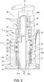
- the movable mechanisms comprise an articulated mechanical device combined with two axial tubular shafts: a main supply shaft and a lower shaft; wherein a lower end of the main supply shaft is connected to a first part of the articulated mechanical device, while a second part of the articulated mechanical device is connected to a lower end of the lower shaft.
- the two coaxial tubular shafts rotate independently via transmission devices, while the main supply shaft is arranged in the inner hole of the lower shaft, which is arranged coaxially around at least one section of the main supply shaft.
- the articulated mechanical device comprises a lower rod-holder crossbar combined with an upper rod-holder crossbar, wherein the diametrically opposed ends of each crossbar are connected in an articulated manner by pairs of rods: first and second.
- Ends of the first rods are connected to the ends of the lower rod-holder crossbar, while some ends of the second rods are connected to the ends of the upper rod-holder crossbar.
- first and second rods are coupled to each other via articulated connections, the injecting pistols being arranged in correspondence therewith.
- the lower rod-holder crossbar is fixed through its centre to the main supply shaft, while the upper rod-holder crossbar is fixed through its centre to the lower shaft.
- Both crossbars are arranged in different parallel planes, which are perpendicular to the direction of both coaxial tubular shafts.
- the articulated connections of the rods with their related rod-holder crossbars comprise screws fixed to the rods, being coupled around said screws some bearings which are spaced by means of separating bushings, wherein the screws rigidly rotate with the inner track of the bearings at the same time that the outer tracks of the latter are coupled to the crossbar mortises, and wherein the two rods and their related rigidly secured screws rotate as a block with respect to the diametrically opposed ends of the rod-holder crossbars.
- the common ends of the articulated connection of the first and second rods create housings, each of them having a friction bushing press-fitted onto the first rod and a self-lubricated bronze bushing press-fitted onto the inner diameter of the second rod, wherein with this arrangement the bronze bushing rotates around the friction bushing, thus allowing the rotation between each pair of rods through their articulated connection.
- the injecting pistols are fixed to the first rods.
- the device for the application of liquids includes two transmissions related to two servomotors: front and rear.
- the front servomotor transmits its movement to an upper shaft of tubular structure, which is arranged in the same axial direction as the lower shaft and above the latter.
- the rear servomotor transmits its movement to the lower shaft.
- the supply of pressure air and liquid fluid to the pneumatically-actuated injecting pistols is carried out by means of the main supply shaft, which rotates jointly with the upper shaft since it is screwed thereto.
- the transmissions are composed of two belts: front and rear; two driving pulleys: front and rear; and two driven pulleys: front and rear.
- a front driven pulley rotates rigidly secured to the upper shaft of tubular structure, since it is coupled to the inner diameter of a front driven pulley and fixed thereto by means of a conical bushing and castellated nut; the upper shaft rotating jointly onto the inner tracks of two ball bearings which are coupled onto a common mortise located on a rear bearing support.
- the rear driven pulley rotates rigidly secured to the lower shaft since it is coupled to the inner diameter of a rear driven pulley and fixed thereto by means of a conical bushing and castellated nut; the lower shaft rotating jointly onto the inner tracks of two ball bearings which are coupled onto a common mortise located on a bearing support.
- the front and rear supports are screwed by means of four screws fixing both bodies onto the base support of the head.
- the main supply shaft is coupled onto a flange of the upper shaft and throughout its inner diameter, which constitutes the means to supply pressure air and liquid fluid to the pneumatically-actuated injecting pistols; wherein said main supply shaft rotates jointly with the upper shaft since it is screwed thereto.
- the head also comprises a first rotating joint to supply pressure air and a second rotating joint for the passing of liquid fluid; such that the first rotating joint comprises two air passageways and is basically composed of two cylindrical bodies: one upper body and one lower body, screwed therebetween, while including different elements to provide rotation capacity and airtightness.
- the lower body contains two inlets defined by two threaded bores for the pressure air inlets aimed at handling the opening/closure of the pneumatically-actuated injecting pistols.
- the second rotating joint directs the liquid fluid towards the injecting pistols; for this purpose it comprises a passageway, being also composed of two cylindrical bodies: one upper body and one lower body, screwed therebetween, while housing different elements to provide said second rotating joint with rotation capacity and airtightness.
- the pressure air passes from the two inlets of the lower body towards two separating bushings and two friction bushings respectively drilled, to connect with two bores that have been arranged on a first tubular shaft and that connect to two tubes both coupled around the main supply shaft, thus extending both ducts towards the lower end thereof, right where the first part of the articulated mechanical device is assembled to transfer the pressure air through several sleeves towards the injecting pistols.
- the airtightness of the two chambers housed inside the first rotating joint for the passing of air includes four retainers arranged in pairs and separated by two separating bushings; wherein the rotation of the rotating joint is transmitted by the main supply shaft via the press-fitting performed between the outer diameter of the latter upon coupling with the inner diameter of the tubular shaft; the main supply shaft rotating jointly with the tubular shaft and, in turn, both rotating with the inner tracks of the two ball bearings onto which the first tubular shaft is likewise press-fitted.
- the outer tracks of the ball bearings are press-fitted onto a common mortise created between the two lower and upper bodies and with the peculiarity that, in order to make the assembly of the first rotating joint more compact, the upper bearing has been arranged fitted onto both bodies.
- the upper body of the second rotating joint is provided with a threaded bore in the upper area to feed the liquid fluid onto an upper chamber provided; housing therein a ceramic tube as passageway of said fluid and connecting with a coupling fixed through a castellated nut, threading said coupling onto the upper end of the main supply shaft; wherein through its inner bore the passing of liquid fluid is facilitated towards the lower end where the first part of the articulated mechanical device is fixed for transferring the liquid material through some sleeves towards the injecting pistols.
- the airtightness of the different chambers of the second rotating joint is obtained by including three retainers, one intended for making the upper chamber hermetic and two for isolating the second lower chamber composed of four bores at 90°, intended for drainage and refrigeration.
- the rotation of the second rotating joint is transmitted by the main supply shaft by means of a coupling, which rotates jointly with the ceramic tube and the inner track of the ball bearing, being the outer track of the latter press-fitted onto the inner diameter of the cylindrical bodies: upper and lower.
- a first separating bushing is arranged onto this second rotating joint to define the cavity created in a drainage chamber between the retainers, and also a second separating bushing the function of which is to enable a chamber created between the lowest retainer and the ball bearing to house the castellated nut, which is in charge of fixing the second rotating joint to the main supply shaft through the coupling it blocks.
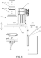
- the lifting device comprises a main fixed support wherein a pneumatic cylinder is coupled, to the stem of which the base support that sustains the assembly of the device for the application of liquid is joined, the base support being joined to a head-holder support.
- the head-holder support includes two slots where two linear guides are screwed; the linear guides are connected to linear bearings, which remain fixed onto two mortises provided in the main fixed support.
- the height of the base support may be adjusted in its connection to the stem of the pneumatic cylinder; having anticipated for such purpose a stem support fixed to the base support and in the interior of which the stem of the pneumatic cylinder is housed, which in turn has been extended having an extender bushing provided with two flat sides.
- the invention is focused on a programmable concentric head for the application of liquid to lids of different shaped that may be integrated to newly manufactured or existing machines, being capable of adapting to any geometry with a quick and easy change in format, consisting in pre-selecting the servomotor/direct-drive motor software of the new geometric profile of the lid to be sealed/repaired.
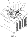
- the concentric head of different shapes (1) is basically composed of two devices, the one designed for the application of liquid (2) and the one for lifting (3). Below is a description of their operations, as well as the parts composing each one of them.
- the first description corresponds to the first option, by means of servomotors (6a), (6b), since its mechanism comprises a greater number of elements, most of which are common to the second option, by means of direct-drive motors (6c), (6d), which will be described further on.
- the device for the application of liquid (2) is supported onto a movable head base support (40) that is part of the lifting device (3), and in turn functions as a link between both devices (2), (3).
- a movable head base support (40) that is part of the lifting device (3), and in turn functions as a link between both devices (2), (3).
- Onto the base support (40) of the head two servomotor supports are screwed: front (47) and rear (48) with different heights for coupling the servomotors (6a), (6b), the base support (40) presenting rails to regulate the supports (47), (48) in order to provide the optimum tension to both transmissions.
- the device for the application of liquid (2) is provided with two transmissions, one for each servomotor (6a), (6b), composed of two belts: front (9a) and rear (9b); two driving pulleys: front (7a) and rear (7b); and two driven pulleys: front (8a) and rear (8b).
- a front driven pulley (8a) rotates rigidly secured to an upper shaft (10a) of tubular structure, since it is coupled to the inner diameter of the driven pulley (8a) and fixed thereto by means of a conical bushing (15a) and castellated nut (16a).
- the upper shaft (10a) rotates jointly onto the inner tracks of two ball bearings (13), (14), which are coupled onto a common mortise located on a front bearing support (11a).
- the device for the application of liquids (2) is composed of a rear bearing support (11b) intended for an analogous function for the assembly of a lower shaft (10b), such that both supports (11a), (11b) are screwed by means of four screws that fix both bodies to the base support (40) of the head.
- a main supply shaft (12) is coupled, also with tubular structure, the function of which, among others, is to supply pressure air and liquid fluid to the pneumatically-actuated injecting pistols (53).
- Said main supply shaft (12) rotates jointly with the upper shaft (10a) since it is screwed thereto.
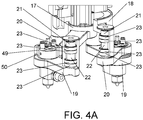
- a lower rod-holder crossbar (17) is coupled and fixed by means of screws, which rotates jointly with the main supply shaft (12).
- Two first rods (19) capable of rotation are articulated on diametrically opposed ends of said lower rod-holder crossbar (17).
- the first rods (19) have been provided with free rotation right on the threaded end and where it is assembled with the lower rod-holder crossbar (17) by including a screw (21) onto which four ball bearings (23) are coupled, located throughout said screw (21), in pairs, these pairs of bearings (23) being spaced apart by means of a separating bushing (22) to provide an exact fit, and which threads said screw (21) onto the first rod (19) through its end.
- the screw (21) rotates jointly with the inner track of the ball bearings (23) at the same time that the outer track of the latter is coupled to the inner diameter of a mortise of the lower rod-holder crossbar (17), such that the first rod (19) and screw (21) rotate in a block as a unique body with respect to the diametrically opposed ends of the lower rod-holder crossbar (17).
- the rear driven pulley (8b) rotates rigidly secured to the lower shaft (10b), since the lower shaft (10b) is coupled to the inner diameter of the rear driven pulley (8b) and fixed thereto by means of a conical bushing (15b) and a castellated nut (16b).
- the lower shaft (10b) rotates jointly onto the inner tracks of two ball bearings (13), (14), which are coupled onto a common mortise located on the rear bearing support (11b).
- the second rods (20) have been provided with free rotation, as its equivalent first rods (19), the same rotation mechanism being designed by means of the bearing assembly (23), separating bushing (22) and screw (21), all of them mentioned above; thus achieving that each second rod (20) and screw (21) rotate in block as a unique body with respect to the diametrically opposed ends of the upper rod-holder crossbar (18).
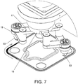
- the four rods (19-20) coupled in pairs onto two different horizontal planes defined by the lower (17) and upper (18) rod-holder crossbars, respectively, are coupled evenly with respect to each other for the rods to create a housing for the pneumatically-actuated injecting pistols (53).
- Each pair of rods (19), (20) articulated to each other is composed of a first rod (19) assembled onto the lower rod-holder crossbar (17) and a second rod (20) assembled onto the upper rod-holder crossbar (18).
- a friction bushing (49) is press-fitted to the first rod (19) and a self-lubricated bronze bushing (50) press-fitted onto the inner diameter of the second rod (20), such that, with this arrangement, the bronze bushing (50) rotates around the friction bushing (49), thus allowing rotation between each pair of rods (19), (20) through their articulated connection, and since each pneumatic injecting pistol (53) is screwed to the first rod (19), it jointly moves along with its movement.
- the assembly composed by the rod-holder crossbars: upper and lower (17-18), and the four rods (19-20), comprise a scissor-like articulated mechanical device provided with two coaxial independent rotation shafts and six articulations, with the peculiarity that two of them coincide with the exact position for the application of liquid and which is, ultimately, where each injecting pistol (53) remains positioned to perform said application.
- the main difference in design found in the concentric head (1) of different shapes concerning the coupling of the two direct-drive motors (6c), (6d) with respect to the servomotors (6a), (6b) is that the two shafts providing rotation to the upper (18) and lower (17) rod-holder crossbars are now the lower shaft (10b) and the main supply shaft (12), respectively, the upper shaft (10a), which was used with the servomotor option (6a), (6b), being eliminated from the design .
- the main supply shaft (12) is directly driven by the motor (6c) while the lower shaft (10b), likewise coupled in a direct manner, is driven by the motor (6d).
- the rest of the components participating in the mechanism for conducting the application of liquid are exactly as described herein when using the option of transmission by means of two servomotors (6a), (6b).
- the first rotating joint (4) has been designed to supply pressure air while handling the opening/closure of the injecting pistol/s (53). It is a first rotating joint (4) with two air passageways and is basically composed of two cylindrical bodies, one upper body (29) and another lower body (28), screwed therebetween, while including different elements to provide rotation capacity and airtightness.
- the lower body (28) contains two inlets defined by two threaded bores (28a) for the pressure air inlets aimed at handling the opening/closure of the pneumatically-actuated injecting pistol/s (53).
- the passing of fluid is carried out from the two inlets of the lower body (28) towards two separating bushings (26) and two friction bushings (27) respectively drilled, to thus connect with two ducts (42) onto which two tubes (51a) and (51b) have been placed, both coupled around the main supply shaft (12), thus extending both ducts towards the lower end thereof, right where it is assembled with the lower rod-holder crossbar (17) and, through two connecting couplings located therein, pressure air is supplied by means of two sleeves towards the injecting pistols (53).
- the airtightness of the two chambers generated inside the first rotating joint (4) for the passing of air has been achieved including four retainers (25) arranged in pairs and spaced by two separating bushings (26) as those previously mentioned.
- the rotation of the rotating joint (4) is transmitted by the main supply shaft (12) through the press-fitting generated between the outer diameter therefrom upon coupling onto the inner diameter of the upper tubular shaft (51).
- the main supply shaft (12) jointly rotates with the tubular shaft (51) and this in turn is fitted against the inner tracks of the two ball bearings (24) onto which said tubular shaft (51a) is likewise press-fitted.
- the outer tracks of the ball bearings (24) are likewise press-fitted onto a common mortise created between the two lower and upper bodies (28-29) and with the peculiarity that, in order to make the assembly of the first rotating joint (4) more compact, the upper bearing (24) has been arranged fitted onto both bodies (28-29).
- the second rotating joint (5) has been designed to supply the liquid fluid (injected material) to the injecting pistol (53). It concerns a rotating joint (5) with one air passageway and it is basically composed of two cylindrical bodies, one upper body (38) and one lower body (37), screwed therebetween, while housing different elements designed to provide said second rotating joint (5) with rotation capacity and airtightness.
- the upper body (38) is provided with a threaded bore (38a) in the upper area to feed the liquid fluid to an upper chamber provided there, housing therein a ceramic tube (31) acting as passageway of said fluid and connecting with a coupling (30) fixed through a castellated nut (33), threading said coupling (30) onto the upper end of the main supply shaft (12); such that through its inner bore the passing of fluid is facilitated to the lower end where it is assembled with the rod-holder crossbar (17), and, by means of a connecting coupling located therein, the liquid material injected through a sleeve is transferred towards the injecting pistol (53).
- the airtightness of the different chambers of the second rotating joint (5) is obtained by including three retainers (35), one intended for making the upper chamber hermetic and two for isolating the second lower chamber composed of four bores at 90°, intended for drainage and refrigeration.
- the rotation of the second rotating joint (5) is transmitted by the main supply shaft (12) via a coupling (30), which rotates jointly with the ceramic tube (31) and with the inner track of a ball bearing (32), being the outer track of the latter press-fitted onto the inner diameter of the cylindrical bodies: upper (38) and lower (37); thus achieving greater strength in the assembly of the second rotating joint (5).
- a first separating bushing (36) is arranged onto this second rotating joint (5) to define the cavity created in the drainage chamber between the retainers (35), and also a second separating bushing (34), the function of which is to enable a chamber created between the lowest retainer (35) and the ball bearing (32) to house the castellated nut (33), which is in charge of fixing the second rotating joint (5) to the main supply shaft (12) through the coupling (30) it blocks.
- the lifting device (3) is basically disposed onto three elements, two of which are movable (40), (41) and one is fixed (39).
- the two movable elements are screwed therebetween and arranged therebetween at 90°, such that one of them is vertically arranged, the one called head-holder support (41), whereas the head base support (40) is horizontally arranged, being the whole mechanism related to the application of liquid of the head on top of it.
- the base support (40) of the lifting device (3) is screwed and arranged at 90° onto the head-holder support (41), such that when the first of them is lifted, the second is displaced vertically, thus displacing the entire device for the application of liquid (2) vertically, modifying the height with respect to the work table (52) of the machine where it is inserted.
- the head-holder support (41) is provided with two slots where two linear guides (44) are screwed.
- the up/down vertical movement of the head-holder support (41) is carried out by displacing the two guides (44) through four linear bearings (43) that are fixed on two mortises provided in the main fixed support (39).
- a pneumatic cylinder (54) has been provided, screwed and embedded on a mortise designed for such purpose and which is located on the rear surface of the main fixed support (39).
- the pneumatic cylinder (54) is provided with pressure air, the stem of the latter pushes the base support (40) displacing the entire device for the application of liquid (2) vertically.
- a stem support (45) has been provided fixed to the base support (40) of the head and in the interior of which the stem of the cylinder (54) is housed, which in turn has been extended, an extender bushing (46) provided with two flat sides being coupled thereto.
- the main fixed support (39) includes four perforations (39a) to fix the entire concentric head of different shapes to the machine where it is to be inserted.
- the programmable concentric head for the application of liquid in lids of different shapes is versatile and, therefore, easily adapted to machines of the Pe ⁇ alver design, as well as to other machines made by other manufacturers, since it entails a compact head, is highly durable, requires minimum space, is highly productive, requires minimum maintenance, is capable of simply and easily exchanging different lid formats, and is capable of working with lids of different geometries with a wide array of sizes and with diverse features for sign-writing/tracing text, among others.
Landscapes
- Coating Apparatus (AREA)
- Automobile Manufacture Line, Endless Track Vehicle, Trailer (AREA)
- Nozzles (AREA)
- Automatic Assembly (AREA)
Claims (16)
- Programmierbarer konzentrischer Kopf zum Auftragen von Flüssigkeit auf Deckel verschiedener Form, der dazu vorgesehen ist, ein flüssiges Fluid in einem Randbereich eines Deckels mithilfe von Pistolen zum Einspritzen des flüssigen Fluids aufzubringen, wobei die Einspritzpistolen mit beweglichen Mechanismen verbunden sind, welche die Einspritzpistolen durch den Umfangsbereich des Deckels ziehen; wobei die beweglichen Mechanismen in einer Vorrichtung für das Auftragen von Flüssigkeit integriert sind, die an einem Grundträger gehalten wird, der Teil einer Hebevorrichtung ist; dadurch gekennzeichnet, dass:- die beweglichen Mechanismen eine gelenkige mechanische Vorrichtung (56) umfassen, die mit zwei koaxialen Hohlwellen kombiniert ist: einer Hauptversorgungswelle (12) und einer unteren Welle (10b); wobei ein unteres Ende der Hauptversorgungswelle (12) mit einem ersten Teil der gelenkigen mechanischen Vorrichtung (56) verbunden ist, während ein zweiter Teil der gelenkigen mechanischen Vorrichtung (56) mit einem unteren Ende der unteren Welle (10b) verbunden ist;- sich die untere Welle (10b) und die Hauptversorgungswelle (12) unabhängig über Getriebemechanismen drehen;- die Hauptversorgungswelle (12) in einer inneren Öffnung der unteren Welle (10b) angeordnet ist, die koaxial rund um mindestens einen Abschnitt der Hauptversorgungswelle (12) angeordnet ist.
- Programmierbarer konzentrischer Kopf zum Auftragen von Flüssigkeit auf Deckel verschiedener Form nach Anspruch 1, dadurch gekennzeichnet, dass:- die gelenkige mechanische Vorrichtung eine untere Stangenhalter-Traverse (17) in Kombination mit einer oberen Stangenhalter-Traverse (18) umfasst, wobei diametral gegenüberliegende Enden der einzelnen Traversen (17), (18) in gelenkiger Weise über Paare aus Stangen: ersten (19) und zweiten (20) verbunden sind;- Enden der ersten Stangen (19) mit Enden der unteren Stangenhalter-Traverse (17) verbunden sind, während Enden der zweiten Stangen (20) mit Enden der oberen Stangenhalter-Traverse (18) verbunden sind;- gemeinsame Enden der ersten und zweiten Stangen miteinander über gelenkige Verbindungen verbunden sind, wobei die Einspritzpistolen (53) in Kontakt damit angeordnet sind;- die untere Stangenhalter-Traverse (17) durch ihre Mitte an der Hauptversorgungswelle (12) fixiert ist, während die obere Stangenhalter-Traverse (18) durch ihre Mitte an der unteren Welle (10b) fixiert ist; wobei die zwei Traversen (17), (18) in verschiedenen parallelen Ebenen angeordnet sind, die lotrecht zu der Richtung der beiden koaxialen Hohlwellen verlaufen.
- Programmierbarer konzentrischer Kopf zum Auftragen von Flüssigkeit auf Deckel verschiedener Formen nach Anspruch 2, dadurch gekennzeichnet, dass die gelenkigen Verbindungen der Stangen (19), (20) mit ihren verbundenen Stangenhalter-Traversen (17), (18) Schrauben (21) umfassen, die an den Stangen (19), (20) fixiert sind, Lager (23), die einander durch Trennbuchsen (22) beabstanden, die um die Schrauben (21) herum gekoppelt sind; wobei sich die Schrauben (21) zusammen mit der inneren Bahn der Lager (23) zu demselben Zeitpunkt bewegen, an dem die äußeren Bahnen der letzteren mit Stangenhalter-Zapfenlöchern (17), (18) verbunden sind; und wobei sich die Stangen (19), (20) und ihre jeweiligen gemeinsam verbundenen Schrauben (21) als ein Block bezüglich der diametral gegenüberliegenden Enden der Stangenhalter-Traversen (17), (18) drehen.
- Programmierbarer konzentrischer Kopf zum Auftragen von Flüssigkeit auf Deckel verschiedener Formen nach einem der vorhergehenden Ansprüche 2 oder 3, dadurch gekennzeichnet, dass Gehäuse in gemeinsamen Enden der gelenkigen Verbindung der ersten und zweiten Stange (19), (20) ausgebildet sind, wobei jedes der Gehäuse eine Reibungsbuchse (49) aufweist, die auf die erste Stange (19) pressgepasst ist, und eine selbstschmierende Bronzebuchse (50), die an den Innendurchmesser der zweiten Stange (20) pressgepasst ist, wobei sich bei dieser Anordnung die Bronzebuchse (50) um die Reibungsbuchse (49) dreht und damit eine Drehung zwischen jedem Paar aus Stangen (19), (20) um deren gelenkige Verbindungen ermöglicht.
- Programmierbarer konzentrischer Kopf zum Auftragen von Flüssigkeit auf Deckel verschiedener Formen nach einem der vorhergehenden Ansprüche 2 bis 4, dadurch gekennzeichnet, dass die Einspritzpistolen (53) an den ersten Stangen (19) fixiert sind.
- Programmierbarer konzentrischer Kopf zum Auftragen von Flüssigkeit auf Deckel verschiedener Form nach einem der vorhergehenden Ansprüche, dadurch gekennzeichnet, dass:- die Vorrichtung zum Auftragen von Flüssigkeiten (2) zwei Getriebe beinhaltet, die mit zwei Servomotoren: vorderer (6a) und hinterer (6b) verbunden sind;- der vordere Servomotor (6a) seine Bewegung auf eine obere Welle (10a) mit einer rohrförmigen Struktur überträgt, die in derselben axialen Richtung wie die untere Welle (10b) und über der letzteren angeordnet ist;- der hintere Servomotor (6b) seine Bewegung auf die untere Welle (10b) überträgt;- die Zufuhr von Druckluft und flüssigem Fluid zu den pneumatisch betätigten Einspritzpistolen (53) über die Hauptversorgungswelle (12) ausgeführt wird, die sich zusammen mit der oberen Welle (10a) dreht, da sie damit verschraubt ist.
- Programmierbarer konzentrischer Kopf zum Auftragen von Flüssigkeit auf Deckel verschiedener Form nach Anspruch 6, dadurch gekennzeichnet, dass:- die Getriebe aus zwei Riemen bestehen: vorne (9a) und hinten (9b), zwei Antriebsscheiben: vorne (7a) und hinten (7b) und zwei Abtriebsscheiben: vorne (8a) und hinten (8b),- an dem Getriebe, das von dem vorderen Servomotor (6a) angetrieben wird, sich eine vordere Abtriebsscheibe (8a) starr mit der oberen Welle (10a) der rohrförmigen Struktur dreht, da sie mit dem Innendurchmesser einer vorderen Abtriebsscheibe (8a) verbunden und daran mithilfe einer konischen Buchse (15a) sowie einer Kronenmutter (16a) fixiert ist; sich die obere Welle (10a) gemeinsam an inneren Bahnen von zwei Kugellagern (13), (14) dreht, die verbunden mit einem gemeinsamen Zapfenloch angeordnet sind, das sich an einem hinteren Traglager (11a) befindet;- an dem Getriebe, das von dem hinteren Servomotor (6b) angetrieben wird, sich die hintere Abtriebsscheibe (8b) starr verbunden mit der unteren Welle (10b) dreht, da sie mit dem Innendurchmesser einer hinteren Abtriebsscheibe (8b) verbunden und daran mithilfe einer konischen Buchse (15b) sowie einer Kronenmutter (16b) fixiert ist; sich die untere Welle (10b) gemeinsam an inneren Bahnen von zwei Kugellagern (13), (14) dreht, die verbunden mit einem gemeinsamen Zapfenloch angeordnet sind, das sich an einem hinteren Traglager (11b) befindet.
- Programmierbarer konzentrischer Kopf zum Auftragen von Flüssigkeit auf Deckel verschiedener Form nach den vorhergehenden Ansprüchen 6 und 7, dadurch gekennzeichnet, dass:- die vorderen (11a) und hinteren (11b) Halterungen symmetrisch mithilfe von vier Schrauben, die an beiden Körpern fixiert sind, an den Grundträger des Kopfes (40) geschraubt sind;- an einen Flansch der oberen Welle (10a) und durch deren Innendurchmesser die Hauptversorgungswelle (12) gekoppelt ist, die das Mittel zum Leiten von Druckluft und flüssigem Fluid zu den pneumatisch betätigten Einspritzpistolen (53) bildet; wobei sich die Hauptversorgungswelle (12) gemeinsam mit der oberen Welle (10a) dreht, da sie damit verschraubt ist.
- Programmierbarer konzentrischer Kopf zum Auftragen von Flüssigkeit auf Deckel verschiedener Formen nach einem der vorhergehenden Ansprüche, wobei der Kopf zusätzlich eine erste Drehverbindung (4) umfasst, um Druckluft zuzuführen, und eine zweite Drehverbindung (5) für den Durchgang von flüssigem Fluid; dadurch gekennzeichnet, dass:- die erste Drehverbindung (4) zwei Luftkanäle umfasst und im Wesentlichen aus zwei zylindrischen Körpern besteht: einem oberen Körper (29) und einem weiteren unteren Körper (28), die dazwischen verschraubt sind, während gleichzeitig verschiedene Elemente enthalten sind, um Drehfähigkeit und Luftdichtigkeit bereitzustellen;- der untere Körper (28) zwei Einlässe (28a) enthält, die durch zwei Gewindebohrungen für die Drucklufteinlässe definiert sind, die auf die Handhabung des Öffnens/Schließens der pneumatischen betätigten Einspritzpistolen (53) abzielen;- die zweite Drehverbindung (5) das flüssige Fluid in Richtung der Einspritzpistolen (53) treibt; umfassend einen Luftkanal, der ebenfalls aus zwei zylindrischen Körpern besteht: einem oberen Körper (38) und einem unteren Körper (37), die dazwischen verschraubt sind, während gleichzeitig verschiedene Elemente enthalten sind, um für die zweite Drehverbindung (5) Drehfähigkeit und Luftdichtigkeit bereitzustellen.
- Programmierbarer konzentrischer Kopf zum Auftragen von Flüssigkeit auf Deckel verschiedener Form nach Anspruch 9, dadurch gekennzeichnet, dass:- der Durchgang von Druckluft aus den zwei Einlässen (28a) des unteren Körpers (28) in Richtung von zwei Trennbuchsen (26) und zwei Reibungsbuchsen (27) ausgeführt wird, die jeweils aufgebohrt sind und somit eine Verbindung mit zwei Leitungen (42) bilden, an welchen zwei Rohre (51a) und (51b) platziert wurden, die beide rund um die Hauptversorgungsachse (12) gekoppelt sind, so dass sich die beiden Leitungen zu dem unteren Ende davon erstrecken, an dem Punkt, an dem der erste Teil der gelenkigen mechanischen Vorrichtung (56) montiert ist, um die Druckluft mithilfe von Muffen in Richtung der Einspritzpistolen (53) zu übertragen.
- Programmierbarer konzentrischer Kopf zum Auftragen von Flüssigkeit auf Deckel verschiedener Form nach Anspruch 10, dadurch gekennzeichnet, dass:- die Luftdichtigkeit von zwei Kammern, die in der ersten Drehverbindung (4) für den Durchgang von Luft erzeugt wird, beinhaltet, dass vier Halterungen (25) in Paaren angeordnet und durch zwei Trennbuchsen (26) getrennt sind; wobei die Drehung der Drehverbindung (4) durch die Hauptversorgungswelle (12) durch die Presspassung übertragen wird, die zwischen dem Außendurchmesser der letzteren bei Kopplung mit dem Innendurchmesser der Hohlwelle (51) durchgeführt wird; sich die Hauptversorgungswelle (12) gemeinsam mit der Hohlwelle (51) dreht und sich gleichzeitig beide mit den inneren Bahnen der zwei Kugellager (24) drehen, auf welche die obere Hohlwelle (51a) ebenfalls pressgepasst ist,- die äußeren Bahnen der Kugellager (24) an ein gemeinsames Zapfenloch pressgepasst sind, das zwischen den zwei Körpern: unterer und oberer (28), (29) ausgebildet ist, und mit der Besonderheit, dass, um die Anordnung der ersten Drehverbindung (4) kompakter zu gestalten, das obere Lager (24) so angeordnet wurde, dass es an beiden Körpern (28), (29) befestigt ist.
- Programmierbarer konzentrischer Kopf zum Auftragen von Flüssigkeit auf Deckel verschiedener Form nach einem der vorhergehenden Ansprüche 9 bis 11, dadurch gekennzeichnet, dass:- der obere Körper (38) der zweiten Drehverbindung (5) mit einer Gewindebohrung (38a) in dem oberen Bereich versehen ist, um das flüssige Fluid zu einer bereitgestellten oberen Kammer zu leiten; wobei darin ein Keramikrohr (31) als Kanal des Fluids angeordnet ist und mit einer Kopplung (30) verbunden ist, die durch eine Kronenmutter (33) fixiert ist, wobei die Kopplung (30) an das obere Ende der Hauptversorgungswelle (12) geschraubt wird; wobei durch deren innere Bohrung der Durchgang von flüssigem Fluid in Richtung des unteren Endes ermöglicht wird, wo der erste Teil der gelenkigen mechanischen Vorrichtung fixiert ist, um das flüssige eingespritzte Material durch einige Muffen in Richtung der Einspritzpistolen (53) zu übertragen.
- Programmierbarer konzentrischer Kopf zum Auftragen von Flüssigkeit auf Deckel verschiedener Form nach Anspruch 12, dadurch gekennzeichnet, dass:- die Luftdichtigkeit der verschiedenen Kammern der zweiten Drehverbindung (5) erzielt wird, indem drei Halterungen (35) enthalten sind, von welchen eine dazu vorgesehen ist, die obere Kammer hermetisch abzuschließen und zwei dafür vorgesehen sind, die zweite untere Kammer zu isolieren, die aus vier Bohrungen auf 90° besteht, die für Abfluss und Kühlung vorgesehen sind;- die Drehung in der zweiten Drehverbindung (5) durch die Hauptversorgungswelle (12) mithilfe einer Kopplung (30) übertragen wird, die sich gemeinsam mit dem Keramikrohr (31) und der inneren Bahn des Kugellagers (32) dreht, wobei die äußere Bahn des letzteren an den Innendurchmesser der zylindrischen Körper: oberer (37) und unterer (38) pressgepasst ist;- eine erste Trennbuchse (36) auf dieser zweiten Drehverbindung (5) angeordnet wurde, um den Hohlraum zu definieren, der in einer Abflusskammer zwischen den Halterungen (35) ausgebildet ist, und außerdem eine zweite Trennbuchse (34), deren Funktion darin besteht, die Aufnahme der Kronenmutter (33) in einer Kammer, die zwischen der untersten Halterung (35) und dem Kugellager (32) gebildet wird, zu ermöglichen, deren Aufgabe darin besteht, die zweite Drehverbindung (5) an der Hauptversorgungswelle (12) durch die Kopplung (30) zu fixieren, die sie blockiert.
- Programmierbarer konzentrischer Kopf zum Auftragen von Flüssigkeit auf Deckel verschiedener Form nach einem der vorhergehenden Ansprüche, dadurch gekennzeichnet, dass die Hebevorrichtung (3) eine feststehende Haupthalterung (39) umfasst, womit ein Pneumatikzylinder (54) verbunden ist, dessen Stange mit dem Grundträger (40) verbunden ist, der die Anordnung der Vorrichtung zum Auftragen von Flüssigkeit (2) trägt, wobei es sich um einen Grundträger (40) handelt, der mit einer Kopfhalterung (41) verbunden ist.
- Programmierbarer konzentrischer Kopf zum Auftragen von Flüssigkeit auf Deckel verschiedener Formen nach Anspruch 14, dadurch gekennzeichnet, dass die Kopfhalterung (41) zwei Schlitze beinhaltet, woran zwei lineare Führungen (44) geschraubt sind, die mit einigen Linearlagern (43) verbunden sind, welche an zwei Lagerlöchern fixiert bleiben, die in der feststehenden Haupthalterung (39) bereitgestellt sind.
- Programmierbarer konzentrischer Kopf zum Auftragen von Flüssigkeit auf Deckel verschiedener Formen nach Anspruch 15, dadurch gekennzeichnet, das der Grundträger (40) die Höhenregulierung an seiner Verbindung mit der Stange des Pneumatikzylinders (54) aufweist; wobei für diesen Zweck eine Stangenhalterung (45) vorgesehen ist, die an dem Grundträger (40) fixiert ist, und in deren Inneren die Stange des Pneumatikzylinders (54) angeordnet ist, die sich wiederum erstreckt, während sie eine Verlängerungsbuchse (46) aufweist, die mit zwei flachen Seiten versehen ist.
Priority Applications (2)
| Application Number | Priority Date | Filing Date | Title |
|---|---|---|---|
| PT14890782T PT3138633T (pt) | 2014-04-30 | 2014-04-30 | Cabeça concêntrica programável para aplicação de líquido em tampas de diferentes formatos |
| PL14890782T PL3138633T3 (pl) | 2014-04-30 | 2014-04-30 | Programowalna głowica koncentryczna do nakładania płynu na pokrywy o różnych kształtach |
Applications Claiming Priority (1)
| Application Number | Priority Date | Filing Date | Title |
|---|---|---|---|
| PCT/ES2014/070381 WO2015166115A1 (es) | 2014-04-30 | 2014-04-30 | Cabezal concéntrico programable para aplicación líquida en tapas multiformato |
Publications (3)
| Publication Number | Publication Date |
|---|---|
| EP3138633A1 EP3138633A1 (de) | 2017-03-08 |
| EP3138633A4 EP3138633A4 (de) | 2017-12-20 |
| EP3138633B1 true EP3138633B1 (de) | 2018-11-21 |
Family
ID=54358209
Family Applications (1)
| Application Number | Title | Priority Date | Filing Date |
|---|---|---|---|
| EP14890782.7A Active EP3138633B1 (de) | 2014-04-30 | 2014-04-30 | Programmierbarer konzentrischer kopf zum auftragen von flüssigkeiten auf deckel verschiedener form |
Country Status (9)
| Country | Link |
|---|---|
| US (1) | US9981280B2 (de) |
| EP (1) | EP3138633B1 (de) |
| CN (1) | CN106660063B (de) |
| DK (1) | DK3138633T3 (de) |
| ES (1) | ES2709005T3 (de) |
| PL (1) | PL3138633T3 (de) |
| PT (1) | PT3138633T (de) |
| TW (1) | TWI629106B (de) |
| WO (1) | WO2015166115A1 (de) |
Families Citing this family (4)
| Publication number | Priority date | Publication date | Assignee | Title |
|---|---|---|---|---|
| DE102016006848B4 (de) | 2016-06-04 | 2025-07-24 | Audi Ag | Achsträger für ein mehrspuriges Kraftfahrzeug |
| CN106984492B (zh) * | 2017-04-12 | 2019-03-26 | 耐世特凌云驱动系统(芜湖)有限公司 | 驱动轴的注油装置 |
| WO2025002845A1 (de) * | 2023-06-26 | 2025-01-02 | Vermes Microdispensing GmbH | Dosiereinrichtung mit rotationskopf |
| CN117531658B (zh) * | 2024-01-09 | 2024-03-22 | 阳光中科(福建)能源股份有限公司 | 一种太阳能电池片边框涂胶机 |
Family Cites Families (9)
| Publication number | Priority date | Publication date | Assignee | Title |
|---|---|---|---|---|
| JPS5992333A (ja) * | 1982-11-19 | 1984-05-28 | Shinriyou Seikan Kk | 缶蓋シ−リングコンパウンドの塗布自動化装置 |
| US4798341A (en) * | 1987-09-28 | 1989-01-17 | The Devilbiss Company | Spray gun for robot mounting |
| ES2156465B1 (es) | 1997-07-21 | 2002-01-16 | Penalver Garcia Jose | Maquina rebarnizadora de tapas de apertura facil. |
| DE10016408C2 (de) * | 2000-04-01 | 2002-11-14 | Hinterkopf Gmbh | Maschine zum Bedrucken oder sonstigen Dekorieren von Hohlkörpern |
| DK1369419T3 (da) * | 2001-03-12 | 2007-09-24 | Ono Pharmaceutical Co | N-phenylarylsulfonamidforbindelse, lægemiddel indeholdende forbindelsen som en aktiv bestanddel, mellemprodukt for forbindelsen og fremgangmåder til fremstilling heraf |
| WO2003103873A1 (es) * | 2002-06-05 | 2003-12-18 | Penalver Garcia Jose | Maquina rebordeadora-engomadora de tapas metalicas de geometria no circular para envases |
| JP5089969B2 (ja) * | 2006-12-04 | 2012-12-05 | 武蔵エンジニアリング株式会社 | 液体材料吐出装置 |
| ES2381348B1 (es) | 2010-10-27 | 2013-05-06 | Industrias Peñalver, S.L. | Cabezal de rebarnizado para tapas de geometría circular. |
| ES2396845B1 (es) * | 2010-12-17 | 2014-01-16 | Industrias Peñalver, S.L. | Cabezal de rebarnizado para tapas. |
-
2014
- 2014-04-30 ES ES14890782T patent/ES2709005T3/es active Active
- 2014-04-30 PT PT14890782T patent/PT3138633T/pt unknown
- 2014-04-30 WO PCT/ES2014/070381 patent/WO2015166115A1/es not_active Ceased
- 2014-04-30 EP EP14890782.7A patent/EP3138633B1/de active Active
- 2014-04-30 PL PL14890782T patent/PL3138633T3/pl unknown
- 2014-04-30 CN CN201480080326.8A patent/CN106660063B/zh active Active
- 2014-04-30 US US15/307,404 patent/US9981280B2/en active Active
- 2014-04-30 DK DK14890782.7T patent/DK3138633T3/en active
- 2014-08-26 TW TW103129403A patent/TWI629106B/zh active
Non-Patent Citations (1)
| Title |
|---|
| None * |
Also Published As
| Publication number | Publication date |
|---|---|
| TW201540371A (zh) | 2015-11-01 |
| US9981280B2 (en) | 2018-05-29 |
| CN106660063A (zh) | 2017-05-10 |
| PT3138633T (pt) | 2019-02-01 |
| ES2709005T3 (es) | 2019-04-12 |
| TWI629106B (zh) | 2018-07-11 |
| US20170050202A1 (en) | 2017-02-23 |
| WO2015166115A1 (es) | 2015-11-05 |
| PL3138633T3 (pl) | 2019-05-31 |
| EP3138633A4 (de) | 2017-12-20 |
| DK3138633T3 (en) | 2019-03-18 |
| CN106660063B (zh) | 2019-06-18 |
| EP3138633A1 (de) | 2017-03-08 |
Similar Documents
| Publication | Publication Date | Title |
|---|---|---|
| EP3138633B1 (de) | Programmierbarer konzentrischer kopf zum auftragen von flüssigkeiten auf deckel verschiedener form | |
| CN103826823B (zh) | 用于注塑模制设备的旋转设备 | |
| CN102729030B (zh) | 轴承压装装置 | |
| CN212311816U (zh) | 一种工件定位工装 | |
| HK1235345B (en) | Programmable concentric head for the application of liquid to lids of different shapes | |
| HK1235345A1 (en) | Programmable concentric head for the application of liquid to lids of different shapes | |
| CN104607972B (zh) | 一种能自动翻转加工活塞冷却喷嘴体孔的夹具 | |
| US20010016090A1 (en) | Fluid pressure cylinder | |
| CN112228755B (zh) | 一种通用型轴承注脂器结构 | |
| CN106078171B (zh) | 一种汽油机箱盖安全组装系统 | |
| CN214686290U (zh) | 一种流体连接器拆卸装置 | |
| CN108214046B (zh) | 一种圆管旋转夹紧机构和圆管内圆加工设备及方法 | |
| CN117548955A (zh) | 一种薄壁钣金组件焊接定位工装及焊接方法 | |
| DE112013000804T5 (de) | Abfüllanordnung | |
| CN223654883U (zh) | 一种高压均质机 | |
| CN106239107A (zh) | 一种汽油机箱盖智能组装系统 | |
| KR102585367B1 (ko) | 다중 헤드를 구비한 가지관 성형 장치 | |
| CN205888518U (zh) | 一种汽油机箱盖智能组装装置 | |
| KR102585371B1 (ko) | 유압식 가지관 성형 장치 | |
| US7244083B1 (en) | Cutting head assembly | |
| CN220093821U (zh) | 一种驱动轴钻铣夹具 | |
| CN205888517U (zh) | 一种汽油机箱盖组装装置 | |
| CN116080021B (zh) | 注射单元及注塑机 | |
| CN223286487U (zh) | 一种蛋糕裱花3d打印装置 | |
| CN119778336B (zh) | 气压及流速可调的气动夹头控制器 |
Legal Events
| Date | Code | Title | Description |
|---|---|---|---|
| STAA | Information on the status of an ep patent application or granted ep patent |
Free format text: STATUS: THE INTERNATIONAL PUBLICATION HAS BEEN MADE |
|
| PUAI | Public reference made under article 153(3) epc to a published international application that has entered the european phase |
Free format text: ORIGINAL CODE: 0009012 |
|
| STAA | Information on the status of an ep patent application or granted ep patent |
Free format text: STATUS: REQUEST FOR EXAMINATION WAS MADE |
|
| 17P | Request for examination filed |
Effective date: 20161102 |
|
| AK | Designated contracting states |
Kind code of ref document: A1 Designated state(s): AL AT BE BG CH CY CZ DE DK EE ES FI FR GB GR HR HU IE IS IT LI LT LU LV MC MK MT NL NO PL PT RO RS SE SI SK SM TR |
|
| AX | Request for extension of the european patent |
Extension state: BA ME |
|
| DAX | Request for extension of the european patent (deleted) | ||
| A4 | Supplementary search report drawn up and despatched |
Effective date: 20171121 |
|
| RIC1 | Information provided on ipc code assigned before grant |
Ipc: B05B 13/04 20060101ALI20171115BHEP Ipc: B21D 51/46 20060101ALI20171115BHEP Ipc: B05B 7/02 20060101ALI20171115BHEP Ipc: B05B 13/02 20060101AFI20171115BHEP Ipc: B05C 5/02 20060101ALI20171115BHEP |
|
| REG | Reference to a national code |
Ref country code: HK Ref legal event code: DE Ref document number: 1235345 Country of ref document: HK |
|
| RIC1 | Information provided on ipc code assigned before grant |
Ipc: B05B 7/02 20060101AFI20180504BHEP Ipc: B05B 14/44 20180101ALI20180504BHEP Ipc: B05B 13/02 20060101ALI20180504BHEP Ipc: B05B 13/04 20060101ALI20180504BHEP Ipc: B05C 5/02 20060101ALI20180504BHEP Ipc: B05C 13/02 20060101ALI20180504BHEP Ipc: B21D 51/46 20060101ALN20180504BHEP |
|
| GRAP | Despatch of communication of intention to grant a patent |
Free format text: ORIGINAL CODE: EPIDOSNIGR1 |
|
| STAA | Information on the status of an ep patent application or granted ep patent |
Free format text: STATUS: GRANT OF PATENT IS INTENDED |
|
| INTG | Intention to grant announced |
Effective date: 20180626 |
|
| GRAJ | Information related to disapproval of communication of intention to grant by the applicant or resumption of examination proceedings by the epo deleted |
Free format text: ORIGINAL CODE: EPIDOSDIGR1 |
|
| GRAL | Information related to payment of fee for publishing/printing deleted |
Free format text: ORIGINAL CODE: EPIDOSDIGR3 |
|
| GRAS | Grant fee paid |
Free format text: ORIGINAL CODE: EPIDOSNIGR3 |
|
| STAA | Information on the status of an ep patent application or granted ep patent |
Free format text: STATUS: REQUEST FOR EXAMINATION WAS MADE |
|
| REG | Reference to a national code |
Ref country code: DE Ref legal event code: R079 Ref document number: 602014036746 Country of ref document: DE Free format text: PREVIOUS MAIN CLASS: B05B0013020000 Ipc: B05B0007020000 |
|
| GRAR | Information related to intention to grant a patent recorded |
Free format text: ORIGINAL CODE: EPIDOSNIGR71 |
|
| STAA | Information on the status of an ep patent application or granted ep patent |
Free format text: STATUS: GRANT OF PATENT IS INTENDED |
|
| INTC | Intention to grant announced (deleted) | ||
| RIC1 | Information provided on ipc code assigned before grant |
Ipc: B05B 13/02 20060101ALI20180911BHEP Ipc: B21D 51/46 20060101ALN20180911BHEP Ipc: B05C 5/02 20060101ALI20180911BHEP Ipc: B05C 13/02 20060101ALI20180911BHEP Ipc: B05B 13/04 20060101ALI20180911BHEP Ipc: B05B 14/44 20180101ALI20180911BHEP Ipc: B05B 7/02 20060101AFI20180911BHEP |
|
| GRAA | (expected) grant |
Free format text: ORIGINAL CODE: 0009210 |
|
| STAA | Information on the status of an ep patent application or granted ep patent |
Free format text: STATUS: THE PATENT HAS BEEN GRANTED |
|
| INTG | Intention to grant announced |
Effective date: 20181008 |
|
| AK | Designated contracting states |
Kind code of ref document: B1 Designated state(s): AL AT BE BG CH CY CZ DE DK EE ES FI FR GB GR HR HU IE IS IT LI LT LU LV MC MK MT NL NO PL PT RO RS SE SI SK SM TR |
|
| REG | Reference to a national code |
Ref country code: CH Ref legal event code: EP |
|
| REG | Reference to a national code |
Ref country code: IE Ref legal event code: FG4D |
|
| REG | Reference to a national code |
Ref country code: AT Ref legal event code: REF Ref document number: 1066942 Country of ref document: AT Kind code of ref document: T Effective date: 20181215 |
|
| REG | Reference to a national code |
Ref country code: DE Ref legal event code: R096 Ref document number: 602014036746 Country of ref document: DE |
|
| REG | Reference to a national code |
Ref country code: CH Ref legal event code: PK Free format text: BERICHTIGUNGEN |
|
| REG | Reference to a national code |
Ref country code: PT Ref legal event code: SC4A Ref document number: 3138633 Country of ref document: PT Date of ref document: 20190201 Kind code of ref document: T Free format text: AVAILABILITY OF NATIONAL TRANSLATION Effective date: 20190124 |
|
| RIC2 | Information provided on ipc code assigned after grant |
Ipc: B05B 13/02 20060101ALI20180911BHEP Ipc: B05C 13/02 20060101ALI20180911BHEP Ipc: B05B 13/04 20060101ALI20180911BHEP Ipc: B21D 51/46 20060101ALN20180911BHEP Ipc: B05B 7/02 20060101AFI20180911BHEP Ipc: B05C 5/02 20060101ALI20180911BHEP Ipc: B05B 14/44 20180101ALI20180911BHEP |
|
| REG | Reference to a national code |
Ref country code: CH Ref legal event code: NV Representative=s name: ISLER AND PEDRAZZINI AG, CH |
|
| REG | Reference to a national code |
Ref country code: NL Ref legal event code: FP |
|
| REG | Reference to a national code |
Ref country code: DK Ref legal event code: T3 Effective date: 20190311 |
|
| REG | Reference to a national code |
Ref country code: ES Ref legal event code: FG2A Ref document number: 2709005 Country of ref document: ES Kind code of ref document: T3 Effective date: 20190412 |
|
| PG25 | Lapsed in a contracting state [announced via postgrant information from national office to epo] |
Ref country code: LT Free format text: LAPSE BECAUSE OF FAILURE TO SUBMIT A TRANSLATION OF THE DESCRIPTION OR TO PAY THE FEE WITHIN THE PRESCRIBED TIME-LIMIT Effective date: 20181121 Ref country code: NO Free format text: LAPSE BECAUSE OF FAILURE TO SUBMIT A TRANSLATION OF THE DESCRIPTION OR TO PAY THE FEE WITHIN THE PRESCRIBED TIME-LIMIT Effective date: 20190221 Ref country code: BG Free format text: LAPSE BECAUSE OF FAILURE TO SUBMIT A TRANSLATION OF THE DESCRIPTION OR TO PAY THE FEE WITHIN THE PRESCRIBED TIME-LIMIT Effective date: 20190221 Ref country code: FI Free format text: LAPSE BECAUSE OF FAILURE TO SUBMIT A TRANSLATION OF THE DESCRIPTION OR TO PAY THE FEE WITHIN THE PRESCRIBED TIME-LIMIT Effective date: 20181121 Ref country code: LV Free format text: LAPSE BECAUSE OF FAILURE TO SUBMIT A TRANSLATION OF THE DESCRIPTION OR TO PAY THE FEE WITHIN THE PRESCRIBED TIME-LIMIT Effective date: 20181121 Ref country code: HR Free format text: LAPSE BECAUSE OF FAILURE TO SUBMIT A TRANSLATION OF THE DESCRIPTION OR TO PAY THE FEE WITHIN THE PRESCRIBED TIME-LIMIT Effective date: 20181121 Ref country code: IS Free format text: LAPSE BECAUSE OF FAILURE TO SUBMIT A TRANSLATION OF THE DESCRIPTION OR TO PAY THE FEE WITHIN THE PRESCRIBED TIME-LIMIT Effective date: 20190321 |
|
| PG25 | Lapsed in a contracting state [announced via postgrant information from national office to epo] |
Ref country code: RS Free format text: LAPSE BECAUSE OF FAILURE TO SUBMIT A TRANSLATION OF THE DESCRIPTION OR TO PAY THE FEE WITHIN THE PRESCRIBED TIME-LIMIT Effective date: 20181121 Ref country code: SE Free format text: LAPSE BECAUSE OF FAILURE TO SUBMIT A TRANSLATION OF THE DESCRIPTION OR TO PAY THE FEE WITHIN THE PRESCRIBED TIME-LIMIT Effective date: 20181121 Ref country code: AL Free format text: LAPSE BECAUSE OF FAILURE TO SUBMIT A TRANSLATION OF THE DESCRIPTION OR TO PAY THE FEE WITHIN THE PRESCRIBED TIME-LIMIT Effective date: 20181121 |
|
| REG | Reference to a national code |
Ref country code: GR Ref legal event code: EP Ref document number: 20190400593 Country of ref document: GR Effective date: 20190509 |
|
| PG25 | Lapsed in a contracting state [announced via postgrant information from national office to epo] |
Ref country code: CZ Free format text: LAPSE BECAUSE OF FAILURE TO SUBMIT A TRANSLATION OF THE DESCRIPTION OR TO PAY THE FEE WITHIN THE PRESCRIBED TIME-LIMIT Effective date: 20181121 |
|
| REG | Reference to a national code |
Ref country code: DE Ref legal event code: R097 Ref document number: 602014036746 Country of ref document: DE |
|
| PG25 | Lapsed in a contracting state [announced via postgrant information from national office to epo] |
Ref country code: SK Free format text: LAPSE BECAUSE OF FAILURE TO SUBMIT A TRANSLATION OF THE DESCRIPTION OR TO PAY THE FEE WITHIN THE PRESCRIBED TIME-LIMIT Effective date: 20181121 Ref country code: SM Free format text: LAPSE BECAUSE OF FAILURE TO SUBMIT A TRANSLATION OF THE DESCRIPTION OR TO PAY THE FEE WITHIN THE PRESCRIBED TIME-LIMIT Effective date: 20181121 Ref country code: RO Free format text: LAPSE BECAUSE OF FAILURE TO SUBMIT A TRANSLATION OF THE DESCRIPTION OR TO PAY THE FEE WITHIN THE PRESCRIBED TIME-LIMIT Effective date: 20181121 Ref country code: EE Free format text: LAPSE BECAUSE OF FAILURE TO SUBMIT A TRANSLATION OF THE DESCRIPTION OR TO PAY THE FEE WITHIN THE PRESCRIBED TIME-LIMIT Effective date: 20181121 |
|
| PLBE | No opposition filed within time limit |
Free format text: ORIGINAL CODE: 0009261 |
|
| STAA | Information on the status of an ep patent application or granted ep patent |
Free format text: STATUS: NO OPPOSITION FILED WITHIN TIME LIMIT |
|
| 26N | No opposition filed |
Effective date: 20190822 |
|
| PG25 | Lapsed in a contracting state [announced via postgrant information from national office to epo] |
Ref country code: SI Free format text: LAPSE BECAUSE OF FAILURE TO SUBMIT A TRANSLATION OF THE DESCRIPTION OR TO PAY THE FEE WITHIN THE PRESCRIBED TIME-LIMIT Effective date: 20181121 |
|
| PG25 | Lapsed in a contracting state [announced via postgrant information from national office to epo] |
Ref country code: LU Free format text: LAPSE BECAUSE OF NON-PAYMENT OF DUE FEES Effective date: 20190430 Ref country code: MC Free format text: LAPSE BECAUSE OF FAILURE TO SUBMIT A TRANSLATION OF THE DESCRIPTION OR TO PAY THE FEE WITHIN THE PRESCRIBED TIME-LIMIT Effective date: 20181121 |
|
| PG25 | Lapsed in a contracting state [announced via postgrant information from national office to epo] |
Ref country code: IE Free format text: LAPSE BECAUSE OF NON-PAYMENT OF DUE FEES Effective date: 20190430 |
|
| PG25 | Lapsed in a contracting state [announced via postgrant information from national office to epo] |
Ref country code: CY Free format text: LAPSE BECAUSE OF FAILURE TO SUBMIT A TRANSLATION OF THE DESCRIPTION OR TO PAY THE FEE WITHIN THE PRESCRIBED TIME-LIMIT Effective date: 20181121 |
|
| PG25 | Lapsed in a contracting state [announced via postgrant information from national office to epo] |
Ref country code: HU Free format text: LAPSE BECAUSE OF FAILURE TO SUBMIT A TRANSLATION OF THE DESCRIPTION OR TO PAY THE FEE WITHIN THE PRESCRIBED TIME-LIMIT; INVALID AB INITIO Effective date: 20140430 Ref country code: MT Free format text: LAPSE BECAUSE OF FAILURE TO SUBMIT A TRANSLATION OF THE DESCRIPTION OR TO PAY THE FEE WITHIN THE PRESCRIBED TIME-LIMIT Effective date: 20181121 |
|
| REG | Reference to a national code |
Ref country code: AT Ref legal event code: UEP Ref document number: 1066942 Country of ref document: AT Kind code of ref document: T Effective date: 20181121 |
|
| PG25 | Lapsed in a contracting state [announced via postgrant information from national office to epo] |
Ref country code: MK Free format text: LAPSE BECAUSE OF FAILURE TO SUBMIT A TRANSLATION OF THE DESCRIPTION OR TO PAY THE FEE WITHIN THE PRESCRIBED TIME-LIMIT Effective date: 20181121 |
|
| PGFP | Annual fee paid to national office [announced via postgrant information from national office to epo] |
Ref country code: PT Payment date: 20250312 Year of fee payment: 12 |
|
| PGFP | Annual fee paid to national office [announced via postgrant information from national office to epo] |
Ref country code: BE Payment date: 20250326 Year of fee payment: 12 Ref country code: GR Payment date: 20250313 Year of fee payment: 12 |
|
| PGFP | Annual fee paid to national office [announced via postgrant information from national office to epo] |
Ref country code: FR Payment date: 20250313 Year of fee payment: 12 Ref country code: PL Payment date: 20250312 Year of fee payment: 12 |
|
| PGFP | Annual fee paid to national office [announced via postgrant information from national office to epo] |
Ref country code: GB Payment date: 20250312 Year of fee payment: 12 |
|
| PGFP | Annual fee paid to national office [announced via postgrant information from national office to epo] |
Ref country code: NL Payment date: 20250401 Year of fee payment: 12 |
|
| PGFP | Annual fee paid to national office [announced via postgrant information from national office to epo] |
Ref country code: DE Payment date: 20250425 Year of fee payment: 12 |
|
| PGFP | Annual fee paid to national office [announced via postgrant information from national office to epo] |
Ref country code: ES Payment date: 20250505 Year of fee payment: 12 Ref country code: DK Payment date: 20250422 Year of fee payment: 12 |
|
| PGFP | Annual fee paid to national office [announced via postgrant information from national office to epo] |
Ref country code: IT Payment date: 20250407 Year of fee payment: 12 |
|
| PGFP | Annual fee paid to national office [announced via postgrant information from national office to epo] |
Ref country code: CH Payment date: 20250501 Year of fee payment: 12 |
|
| PGFP | Annual fee paid to national office [announced via postgrant information from national office to epo] |
Ref country code: AT Payment date: 20250423 Year of fee payment: 12 |
|
| PGFP | Annual fee paid to national office [announced via postgrant information from national office to epo] |
Ref country code: TR Payment date: 20250425 Year of fee payment: 12 |