EP3137969B1 - Détermination et application de la direction du mouvement - Google Patents
Détermination et application de la direction du mouvement Download PDFInfo
- Publication number
- EP3137969B1 EP3137969B1 EP15716241.3A EP15716241A EP3137969B1 EP 3137969 B1 EP3137969 B1 EP 3137969B1 EP 15716241 A EP15716241 A EP 15716241A EP 3137969 B1 EP3137969 B1 EP 3137969B1
- Authority
- EP
- European Patent Office
- Prior art keywords
- motion direction
- motion
- mobile device
- identified
- implementations
- Prior art date
- Legal status (The legal status is an assumption and is not a legal conclusion. Google has not performed a legal analysis and makes no representation as to the accuracy of the status listed.)
- Not-in-force
Links
Images


Classifications
-
- G—PHYSICS
- G01—MEASURING; TESTING
- G01P—MEASURING LINEAR OR ANGULAR SPEED, ACCELERATION, DECELERATION, OR SHOCK; INDICATING PRESENCE, ABSENCE, OR DIRECTION, OF MOVEMENT
- G01P13/00—Indicating or recording presence, absence, or direction, of movement
- G01P13/02—Indicating direction only, e.g. by weather vane
-
- G—PHYSICS
- G06—COMPUTING; CALCULATING OR COUNTING
- G06F—ELECTRIC DIGITAL DATA PROCESSING
- G06F3/00—Input arrangements for transferring data to be processed into a form capable of being handled by the computer; Output arrangements for transferring data from processing unit to output unit, e.g. interface arrangements
- G06F3/01—Input arrangements or combined input and output arrangements for interaction between user and computer
- G06F3/011—Arrangements for interaction with the human body, e.g. for user immersion in virtual reality
-
- G—PHYSICS
- G01—MEASURING; TESTING
- G01B—MEASURING LENGTH, THICKNESS OR SIMILAR LINEAR DIMENSIONS; MEASURING ANGLES; MEASURING AREAS; MEASURING IRREGULARITIES OF SURFACES OR CONTOURS
- G01B7/00—Measuring arrangements characterised by the use of electric or magnetic techniques
- G01B7/003—Measuring arrangements characterised by the use of electric or magnetic techniques for measuring position, not involving coordinate determination
-
- G—PHYSICS
- G01—MEASURING; TESTING
- G01C—MEASURING DISTANCES, LEVELS OR BEARINGS; SURVEYING; NAVIGATION; GYROSCOPIC INSTRUMENTS; PHOTOGRAMMETRY OR VIDEOGRAMMETRY
- G01C19/00—Gyroscopes; Turn-sensitive devices using vibrating masses; Turn-sensitive devices without moving masses; Measuring angular rate using gyroscopic effects
-
- G—PHYSICS
- G01—MEASURING; TESTING
- G01C—MEASURING DISTANCES, LEVELS OR BEARINGS; SURVEYING; NAVIGATION; GYROSCOPIC INSTRUMENTS; PHOTOGRAMMETRY OR VIDEOGRAMMETRY
- G01C21/00—Navigation; Navigational instruments not provided for in groups G01C1/00 - G01C19/00
- G01C21/10—Navigation; Navigational instruments not provided for in groups G01C1/00 - G01C19/00 by using measurements of speed or acceleration
- G01C21/12—Navigation; Navigational instruments not provided for in groups G01C1/00 - G01C19/00 by using measurements of speed or acceleration executed aboard the object being navigated; Dead reckoning
-
- G—PHYSICS
- G01—MEASURING; TESTING
- G01C—MEASURING DISTANCES, LEVELS OR BEARINGS; SURVEYING; NAVIGATION; GYROSCOPIC INSTRUMENTS; PHOTOGRAMMETRY OR VIDEOGRAMMETRY
- G01C22/00—Measuring distance traversed on the ground by vehicles, persons, animals or other moving solid bodies, e.g. using odometers, using pedometers
- G01C22/006—Pedometers
-
- G—PHYSICS
- G01—MEASURING; TESTING
- G01P—MEASURING LINEAR OR ANGULAR SPEED, ACCELERATION, DECELERATION, OR SHOCK; INDICATING PRESENCE, ABSENCE, OR DIRECTION, OF MOVEMENT
- G01P15/00—Measuring acceleration; Measuring deceleration; Measuring shock, i.e. sudden change of acceleration
-
- G—PHYSICS
- G06—COMPUTING; CALCULATING OR COUNTING
- G06F—ELECTRIC DIGITAL DATA PROCESSING
- G06F3/00—Input arrangements for transferring data to be processed into a form capable of being handled by the computer; Output arrangements for transferring data from processing unit to output unit, e.g. interface arrangements
- G06F3/01—Input arrangements or combined input and output arrangements for interaction between user and computer
- G06F3/017—Gesture based interaction, e.g. based on a set of recognized hand gestures
-
- G—PHYSICS
- G06—COMPUTING; CALCULATING OR COUNTING
- G06F—ELECTRIC DIGITAL DATA PROCESSING
- G06F3/00—Input arrangements for transferring data to be processed into a form capable of being handled by the computer; Output arrangements for transferring data from processing unit to output unit, e.g. interface arrangements
- G06F3/01—Input arrangements or combined input and output arrangements for interaction between user and computer
- G06F3/03—Arrangements for converting the position or the displacement of a member into a coded form
- G06F3/033—Pointing devices displaced or positioned by the user, e.g. mice, trackballs, pens or joysticks; Accessories therefor
- G06F3/0346—Pointing devices displaced or positioned by the user, e.g. mice, trackballs, pens or joysticks; Accessories therefor with detection of the device orientation or free movement in a 3D space, e.g. 3D mice, 6-DOF [six degrees of freedom] pointers using gyroscopes, accelerometers or tilt-sensors
-
- G—PHYSICS
- G06—COMPUTING; CALCULATING OR COUNTING
- G06F—ELECTRIC DIGITAL DATA PROCESSING
- G06F3/00—Input arrangements for transferring data to be processed into a form capable of being handled by the computer; Output arrangements for transferring data from processing unit to output unit, e.g. interface arrangements
- G06F3/01—Input arrangements or combined input and output arrangements for interaction between user and computer
- G06F3/03—Arrangements for converting the position or the displacement of a member into a coded form
- G06F3/033—Pointing devices displaced or positioned by the user, e.g. mice, trackballs, pens or joysticks; Accessories therefor
- G06F3/038—Control and interface arrangements therefor, e.g. drivers or device-embedded control circuitry
Definitions
- This disclosure relates generally to techniques for determining a direction of motion, and more particularly, to a mobile device capable of estimating a direction of motion based on input from one or more sensors.
- a variety of existing and anticipated applications for mobile electronic devices utilize knowledge of the mobile device's position, orientation, or motion direction. For example, in situations in which a person who is carrying a mobile device is walking or otherwise moving about, it can be useful for the mobile device to have the capability to determine the direction of motion or other motion information concerning the person's movement.
- Other motion information can include, for example, instantaneous and average velocities and accelerations.
- Such motion information can be useful for pedestrian dead-reckoning applications in which the mobile device attempts to determine its motion direction autonomously based on its own sensors without aid or corrections obtained by a Global Positioning System (GPS) and without aid or corrections obtained through other external means such as, for example, over a Wi-Fi or other wireless connection.
- GPS Global Positioning System
- Such dead-reckoning use cases can exist when, for example, the mobile device is out of an area where GPS, cellular, Wi-Fi or other wireless signals are available, or when transmitters or receivers for receiving data via such signals are turned off or disabled.
- the uncertainties in motion direction and position generally continue to grow until external feedback or corrections are received.
- the reliability of an estimated motion direction and related motion information can decrease significantly over time and even render the estimations useless.
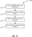
- One innovative aspect of the subject matter described in this disclosure can be implemented in a method that includes obtaining acceleration data for a mobile device in each of one or more directions.
- the method also includes calculating, by a plurality of motion direction estimation modules executing within the mobile device, a plurality of respective estimated motion directions for the mobile device relative to a coordinate system.
- each of the respective motion direction estimation modules uses a respective set of parameters and calculates the respective estimated motion direction based at least in part on the acceleration data and the respective set of parameters.
- the method also includes determining a reliability metric for each of the estimated motion directions.
- the method also includes identifying the reliability metric that indicates the greatest reliability.
- the method also includes identifying the motion direction corresponding to the identified reliability metric.
- the method further includes generating a resultant motion direction based at least in part on the identified reliability metric.
- generating the resultant motion direction based at least in part on the example, instantaneous and average velocities and accelerations.
- Such motion information can be useful for pedestrian dead-reckoning applications in which the mobile device attempts to determine its motion direction autonomously based on its own sensors without aid or corrections obtained by a Global Positioning System (GPS) and without aid or corrections obtained through other external means such as, for example, over a Wi-Fi or other wireless connection.
- GPS Global Positioning System
- Such dead-reckoning use cases can exist when, for example, the mobile device is out of an area where GPS, cellular, Wi-Fi or other wireless signals are available, or when transmitters or receivers for receiving data via such signals are turned off or disabled.
- the uncertainties in motion direction and position generally continue to grow until external feedback or corrections are received.
- the reliability of an estimated motion direction and related motion information can decrease significantly over time and even render the estimations useless. Attention is drawn to WO 2014/039552 A1 describing a processing apparatus that determines an estimated direction of motion of an entity physically associated with a device having a plurality of sensors for generating an estimate of a navigational state of the device.
- the estimated direction of motion is based at least in part on a device-to-frame orientation corresponding to an orientation of the device relative to a predefined inertial frame of reference, and an estimated device-to-entity orientation corresponding to an orientation of the device relative to a direction of motion of the entity.
- the processing apparatus divides the change in the device-to-frame orientation between a change in the estimated direction of motion of the entity and a change in the estimated device-to-entity orientation, and updates the estimated direction of motion of the entity based on the division of the change in the device-to-frame orientation.
- the apparatus includes an evaluation object value acquisition unit that acquires an evaluation object value from map information stored in a storage medium.
- a measurement value acquisition unit acquires measurement values for the evaluation object value using a sensor installed in a vehicle.
- a reliability evaluation unit selects a reliability evaluation method to evaluate the reliability of the evaluation object value based on a current measured value and the dispersion of the measured values. Attention is also drawn to US 2012/059583 A1 describing a method of error compensation for an inertial measurement unit. The method comprises providing a first object including an inertial measurement unit, providing a second object proximal to the first object, and determining an initial position and orientation of the first object.
- a motion update is triggered for the inertial measurement unit when the second object is stationary with respect to a ground surface.
- At least one position vector is measured between the first object and the second object when the first object is in motion and the second object is stationary.
- a distance, direction, and orientation of the second object with respect to the first object are calculated using the at least one position vector.
- An error correction is then determined for the inertial measurement unit from the calculated distance, direction, and orientation of the second object with respect to the first object.
- One innovative aspect of the subject matter described in this disclosure can be implemented in a method that includes obtaining acceleration data for a mobile device in each of one or more directions.
- the method also includes calculating, by a plurality of motion direction estimation modules executing within the mobile device, a plurality of respective estimated motion directions for the mobile device relative to a coordinate system.
- each of the respective motion direction estimation modules uses a respective set of parameters and calculates the respective estimated motion direction based at least in part on the acceleration data and the respective set of parameters.
- the method also includes determining a reliability metric for each of the estimated motion directions.
- the method also includes identifying the reliability metric that indicates the greatest reliability.
- the method also includes identifying the motion direction corresponding to the identified reliability metric.
- the method further includes generating a resultant motion direction based at least in part on the identified reliability metric.
- generating the resultant motion direction based at least in part on the identified reliability metric includes selecting the identified motion direction as the resultant motion direction.
- the method also includes identifying a second reliability metric indicating a next greatest reliability and a respective second identified motion direction.
- generating the resultant motion direction includes selecting the two identified motion directions and combining the two identified motion directions to generate the resultant motion direction.
- the method also includes comparing the identified reliability metric to a threshold. In some such implementations, generating the resultant motion direction includes selecting the identified motion direction only when the identified reliability metric is above the threshold. In some such implementations, when the identified reliability metric is below the threshold, generating the resultant motion direction based at least in part on the identified reliability metric includes selecting a motion direction calculated by a one of the motion direction estimation modules from which an immediately previous motion direction was selected as the resultant motion direction. In some other implementations, when the identified reliability metric is below the threshold, generating the resultant motion direction includes selecting a motion direction calculated by a one of the motion direction estimation modules that uses a default set of parameters as the resultant motion direction.
- the method also includes identifying an orientation of the mobile device relative to the coordinate system based on the acceleration data or other orientation data.
- each motion direction estimation module also calculates the respective estimated motion direction of the mobile device based at least in part on the orientation.
- the orientation data can include one or both of gyroscopic data and magnetometer data.
- the method also includes tracking a number of steps taken by a person carrying the mobile device or to which the mobile device is attached. In some such implementations, the method is performed within a moving window of time and each set of parameters includes a respective window length corresponding to a respective number of steps. In some implementations, each set of parameters includes a phase offset between vertical and horizontal components of the acceleration data.
- a mobile device that includes one or more sensors configured to measure acceleration data for the mobile device in each of one or more directions.
- the mobile device also includes one or more processors and a memory storing instructions that, when executed by the one or more processors, implement a plurality of modules.
- the plurality of modules includes a plurality of motion direction estimation modules configured to calculate a plurality of respective estimated motion directions for the mobile device relative to a coordinate system. In calculating the estimated motion directions, each of the respective motion direction estimation modules uses a respective set of parameters and calculates the respective estimated motion direction based at least in part on the acceleration data and the respective set of parameters.
- the plurality of modules also includes a plurality of reliability metric computation modules configured to determine a plurality of respective reliability metrics for the respective estimated motion directions.
- the plurality of modules also includes a selection module configured to identify the reliability metric that indicates the greatest reliability, identify the motion direction corresponding to the identified reliability metric, and generate a resultant motion direction based at least in part on the identified reliability metric.
- the selection module is configured to select the identified motion direction as the resultant motion direction.
- the selection module is further configured to identify a second reliability metric indicating a next greatest reliability and a respective second identified motion direction. In some such implementations, the selection module can be configured to select the two identified motion directions and combine the two identified motion directions to generate the resultant motion direction.
- the plurality of modules further includes a comparator configured to compare the identified reliability metric to a threshold.
- the selection module is configured to select the identified motion direction only when the identified reliability metric is above the threshold.
- the selection module is configured to select the motion direction calculated by a one of the motion direction estimation modules from which an immediately previous motion direction was selected as the resultant motion direction.
- the selection module is configured to select the motion direction calculated by a one of the motion direction estimation modules that uses a default set of parameters as the resultant motion direction.
- the plurality of modules further includes an orientation determination module configured to determine an orientation of the mobile device relative to the coordinate system based on the acceleration data or other orientation data.
- each motion direction estimation module is further configured to calculate the respective estimated motion direction of the mobile device relative to the coordinate system based at least in part on the orientation.
- the orientation data can include one or both of gyroscopic data and magnetometer data.
- the plurality of modules further includes a step detection module configured to track a number of steps taken by a person carrying the mobile device or to which the mobile device is attached.
- each set of parameters includes a respective window length corresponding to a respective number of steps.
- each set of parameters includes a phase offset between vertical and horizontal components of the acceleration data.
- Another innovative aspect of the subject matter described in this disclosure can be implemented in tangible computer-readable storage media including non-transitory instructions that, when executed by one or more processors, are configured to receive acceleration data for a mobile device in each of one or more directions.
- the instructions also are configured to calculate, using a plurality of motion direction estimation modules, a plurality of respective estimated motion directions for the mobile device relative to a coordinate system.
- each of the motion direction estimation modules uses a respective set of parameters and calculates the respective estimated motion direction based at least in part on the acceleration data and the respective set of parameters.
- the instructions also are configured to determine a reliability metric for each of the estimated motion directions.
- the instructions also are configured to identify the reliability metric that indicates the greatest reliability.
- the instructions also are configured to identify the motion direction corresponding to the identified reliability metric.
- the instructions are further configured to generate a resultant motion direction based at least in part on the identified reliability metric.
- the instructions for generating the resultant motion direction include instructions to select the identified motion direction as the resultant motion direction.
- the media further include instructions for identifying a second reliability metric indicating a next greatest reliability and a respective second identified motion direction. In some such implementations, the media further includes instructions to select the two identified motion directions and combine the two identified motion directions to generate the resultant motion direction.
- the media further include instructions for comparing the identified reliability metric to a threshold. In some such implementations, the media further includes instructions to select the identified motion direction only when the identified reliability metric is above the threshold. In some such implementations, the media further includes instructions to, when the identified reliability metric is below the threshold, select the motion direction calculated by a one of the motion direction estimation modules from which an immediately previous motion direction was selected as the resultant motion direction. In some other implementations, the media further includes instructions to, when the identified reliability metric is below the threshold, select the motion direction calculated by a one of the motion direction estimation modules that uses a default set of parameters as the resultant motion direction.
- the media further includes instructions for determining an orientation of the mobile device relative to the coordinate system based on the acceleration data or other orientation data. In some such implementations, calculating the respective estimated motion direction of the mobile device relative to the coordinate system also is based at least in part on the orientation.
- the media further include instructions for tracking a number of steps taken by a person carrying the mobile device or to which the mobile device is attached.
- each set of parameters includes a respective window length corresponding to a respective number of steps.
- each set of parameters includes a phase offset between vertical and horizontal components of the acceleration data.
- the described implementations can be included in or associated with a variety of mobile electronic devices such as, but not limited to: mobile telephones, multimedia Internet enabled cellular telephones, smartphones, mobile television receivers, Bluetooth® devices, personal data assistants (PDAs), wireless electronic mail receivers, hand-held or portable computers, netbooks, notebooks, smartbooks, tablets, global positioning system (GPS) receivers/navigators, cameras, digital media players (for example, MP3 players), camcorders, portable game consoles, wrist watches, and electronic reading devices (for example, e-readers), among other possible devices.
- PDAs personal data assistants
- GPS global positioning system
- the teachings are not intended to be limited to the implementations depicted solely in the Figures, but instead have wide applicability as will be readily apparent to one having ordinary skill in the art.
- Some implementations relate to devices, apparatus, methods, or computer-readable storage media including instructions for calculating a reliability metric for determining a measure of reliability in an estimated motion vector M. Some implementations relate to apparatus, methods, or computer-readable storage media including instructions for fitting acceleration data or data derived from such acceleration data to a bimodal probability distribution and for determining a direction of motion M based on the bimodal probability distribution. Some implementations relate to apparatus, methods, or computer-readable storage media including instructions for selecting one or more parameters to determine a direction of motion M. For example, a use case can be identified and one or more parameters can be adjusted or optimized to more accurately estimate the direction of motion M.
- Some other implementations relate to apparatus, methods, or computer-readable storage media including instructions for determining, in parallel, a plurality of estimated directions of motion M, where each estimated direction of motion is based on a different set of parameters predefined for a corresponding use case.
- the direction of motion M having the highest respective reliability metric is selected as the output.
- a more reliable (or “certain,” “accurate,” or “precise”) estimated motion direction M can be determined; and a measure of reliability of the estimated motion direction M can be determined to, for example, make a determination as to how to select a future estimated motion direction or how to use the estimated motion direction M.
- a network interface configured to communicate with a GPS, SNS, or other positioning or navigation system is turned off or otherwise disabled as long as the reliability metric for an estimated motion direction M is above a threshold value.
- the network interface is turned on or otherwise enabled so that positioning or other calibration data can be received to correct or refine the estimated motion direction M.
- FIGS 1A and 1B are system block diagrams illustrating an example mobile device 100.
- the mobile device 100 can be, for example, a smart phone, a cellular phone or a mobile telephone.
- some of the same components of the mobile device 100, or variations thereof, also are illustrative of various types of other mobile devices including display devices and computing devices such as computers, tablets, e-readers, gaming devices and other hand-held devices and portable media devices.
- the mobile device 100 includes a housing 102, a display 104, an antenna 106, a speaker 108, an input device 110 and a microphone 112.
- the housing 102 can be formed by any of a variety of manufacturing processes, including injection molding and vacuum forming.
- the housing 102 can be made from any of a variety of materials, including plastic, metal, glass, rubber and ceramic, or a combination of these or other materials.
- the housing 102 can include removable portions (not shown) that can be interchanged with other removable portions of different color, or containing different logos, pictures, or symbols.
- the display 104 can be or can include one or more of any of a variety of types of displays, including a bi-stable or analog display.
- the display 104 can be a flat-panel display, such as an active matrix display.
- the display 104 can be a plasma display, an electroluminescent display (ELD), a light-emitting diode (LED) display, an organic LED (OLED) display, a liquid-crystal display (LCD), a super-twisted nematic (STN) LCD, or thin-film transistor (TFT) LCD.
- the display 104 also can be or can include an interferometric modulator (IMOD)-based display.
- an IMOD display element includes a pair of conductive plates, one or both of which can be transparent and/or reflective, wholly or in part, and capable of relative motion upon application of an appropriate electrical signal.
- one plate can include a stationary layer deposited over, on or supported by a substrate and the other plate can include a reflective membrane separated from the stationary layer by an air gap. The position of one plate in relation to another can change the optical interference of light incident on the IMOD display element.
- IMOD-based display devices have a wide range of applications, and may be used in improving existing products and creating new products, especially those with display capabilities.
- the mobile device 100 can include additional components at least partially enclosed within the housing 102.
- Figure 1B illustrates various example components that can be included at least partially within the housing 102.
- the mobile device 100 includes a network interface 114 that can include the antenna 106, which can be coupled with a transceiver 116.
- the network interface 114 can be a source for image data that could be displayed on the display 104 of the mobile device 100.
- the transceiver 116 is connected to a processor 120, which is connected to conditioning hardware 122.
- the conditioning hardware 122 can condition a signal (for example, filter or otherwise manipulate the signal), such as that received or transmitted via the transceiver 116 and the network interface 114.
- the conditioning hardware 122 can be connected to the speaker 108 and the microphone 112.
- the processor 120 also can be connected to the input device 110 (which may collectively refer to a number of input devices of various types and incorporating various input mechanisms and sensing technologies).
- the processor 120 also can be connected to a driver controller 124.
- the driver controller 124 can be coupled to a frame buffer 126 and to an array driver 128, which in turn can be coupled to drive the display 104.
- the network interface 114 can collectively refer to a number of network interfaces usable to exchange data over a variety of types of wireless connections according to a variety of network protocols, which may include both proprietary and non-proprietary protocols, and for a variety of applications.
- the network interface 114 can transmit and receive positioning data (also referred to herein generally as "calibration data"), such as that received from a GPS or Satellite Navigation System (SNS), as described below.
- the network interface 114 also can transmit and receive telephone data, such as that received from cellular towers or base stations.
- the network interface 114 also can transmit and receive such data or other data over a Wi-Fi or other wireless connection over one or more networks.
- the antenna 106 can generally transmit and receive various signals.
- the antenna 106 transmits and receives radio frequency (RF) signals according to the IEEE 16.11 standard, including IEEE 16.11(a), (b), or (g), or the IEEE 802.11 standard, including IEEE 802.11a, b, g, n, and further implementations thereof.
- the antenna 106 transmits and receives RF signals according to the Bluetooth® standard.
- the antenna 106 can be designed to receive code division multiple access (CDMA), frequency division multiple access (FDMA), time division multiple access (TDMA), Global System for Mobile communications (GSM), GSM/General Packet Radio Service (GPRS), Enhanced Data GSM Environment (EDGE), Terrestrial Trunked Radio (TETRA), Wideband-CDMA (W-CDMA), Evolution Data Optimized (EV-DO), 1xEV-DO, EV-DO Rev A, EV-DO Rev B, High Speed Packet Access (HSPA), High Speed Downlink Packet Access (HSDPA), High Speed Uplink Packet Access (HSUPA), Evolved High Speed Packet Access (HSPA+), Long Term Evolution (LTE), AMPS, or other known signals that are used to communicate within a wireless network, such as a system utilizing 3G, 4G or 5G technology.
- CDMA code division multiple access
- FDMA frequency division multiple access
- TDMA Time division multiple access
- GSM Global System for Mobile communications
- GPRS GSM
- the network interface 114 also can have some conditioning or processing capabilities to relieve, for example, data conditioning or processing requirements of the conditioning hardware 122 or the processor 120.
- the transceiver 116 can pre-process the signals received from the antenna 106 so that they can be received by and further manipulated by the conditioning hardware 122 or the processor 120.
- the transceiver 116 also can process signals received from the conditioning hardware 122 or the processor 120 so that they can be transmitted from the mobile device 100 via the antenna 106.
- the processor 120 controls the overall operations of the mobile device 100.
- the processor 120 can include one or more microcontrollers, CPUs, or logic units to control operation of the mobile device 100 (also referred to herein collectively as "the processor 120").
- the conditioning hardware 122 can include amplifiers and filters for transmitting signals to the speaker 108, and for receiving signals from the microphone 112.
- the conditioning hardware 122 can be implemented as discrete components within the mobile device 100, or can be incorporated within or integrated with the processor 120 or other components.
- the input device 110 can allow, for example, a user to control the operation of the mobile device 100.
- the input device 110 may collectively refer to a number of distinct or integrated input devices based on a variety of input mechanisms and sensing technologies.
- the input device 110 can include a keypad, such as a QWERTY keyboard or a telephone keypad, a button, a switch, a rocker, a touch-sensitive screen, a touch-sensitive screen integrated with the display 104, or a pressure- or heat-sensitive membrane.
- the microphone 112 also can be an input device for the mobile device 100. In some implementations, voice commands through the microphone 112 can be used for controlling operations of the mobile device 100.
- a power supply 130 can provide power to some or all of the components of the mobile device 100 described herein including the processor 120 and the display 104.
- the power supply 130 can include one or more of a variety of energy storage devices.
- the power supply 130 can include a rechargeable battery, such as a nickel-cadmium battery or a lithium-ion battery.
- the rechargeable battery can be chargeable using power coming from, for example, a wall socket (or "outlet") or a photovoltaic device or array.
- the rechargeable battery can be wirelessly chargeable via a magnetic induction or other mechanism.
- the power supply 130 also can be a renewable energy source, a capacitor, or a solar cell, including a plastic solar cell or solar-cell paint.
- the mobile device 100 also includes a memory 132 connected with the processor 120.
- the memory 132 can collectively refer to any of a number of suitable data storage devices or mechanisms.
- the memory 132 includes one or more volatile storage devices and one or more non-volatile storage devices.
- the memory 132 also can include one or more removable memory devices such as memory cards, memory sticks, flash drives or other removable memory devices or components. Additionally, while described as separate from the processor 120, some or all of the memory 132 can be provided with the processor 120, provided on the same chip or die as the processor 120, or be included as part of a package including the processor 120.
- the mobile device 100 also includes a suite (or "set") 134 of one or more sensors.
- the sensors in the sensor suite 134 are communicatively connected with the processor 120, and in some implementations, also with the conditioning hardware 122 or some other conditioning hardware within the housing 102.
- the sensor suite 134 includes some conditioning or processing capabilities for conditioning or processing the signals measured by or obtained from the sensors of the sensor suite 134 before such signals are communicated or passed to the processor 120 or conditioning hardware.
- Some of the sensors in the sensor suite 134 can be inertial sensors, and thus, the sensor suite 134 also may be referred to as an inertial measurement unit (IMU) 134.
- IMU inertial measurement unit
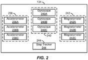
- Figure 2 illustrates a system block diagram of an example sensor suite 134.
- the sensors in the sensor suite 134 are illustrated as a number of individual components located within a single sensor package, some or all of the sensors in the sensor suite 134 can be discrete components or combined or integrated into one or more sensor packages located within the housing 102 of the mobile device 100.
- the sensor suite 134 includes three linear accelerometers 236A, 236B and 236C, each of which measures linear acceleration or velocity (also referred to herein collectively as “linear acceleration data,” “linear velocity data” or generally as “motion data”) along a particular axis of a mobile device coordinate system.
- each of the linear accelerometers 236A, 236B and 236C measures linear acceleration data along a particular respective orthogonal axis of a Cartesian coordinate system.
- the functions of the three linear accelerometers 236A, 236B and 236C can be combined or integrated into a single three-dimensional accelerometer 236.
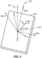
- Figure 3 shows an example mobile device coordinate system 300 relative to an example mobile device 100.
- the mobile device coordinate system 300 (also referred to as the "IMU coordinate system 300") is defined and fixed relative to the mobile device 100 itself.
- Such a coordinate system 300 is an example of a "device-centric" coordinate system in which an origin of three orthogonal axes 338A, 338B and 338C lies within the mobile device 100.
- the origin of the mobile device coordinate system 300 may be located at the geometric center of the mobile device 100, at the center of mass of the mobile device 100, at a corner of the mobile device 100 or at another suitable or convenient reference location.
- the mobile device coordinate system 300 includes the three orthogonal axes 338A, 338B and 338C that extend along respective width, length and depth dimension directions of the mobile device.
- the first linear accelerometer 236A can measure linear acceleration data (also referred to herein simply as "linear acceleration") along the first axis 338A
- the second linear accelerometer 236B can measure linear acceleration data along the second orthogonal axis 338B
- the third linear accelerometer 236C can measure linear acceleration data along the third orthogonal axis 338C.
- Also superimposed on the mobile device 100 is an example East, North and Up (ENU) Cardinal-based Cartesian coordinate system 301 showing East (E), North (N) and Up (U) directions.
- the direction of gravity (G) is defined as the direction corresponding to the positive direction of the axis 338B.
- the sensor suite 134 of Figure 2 includes three gyroscopes 240A, 240B and 240C, each of which measures angular acceleration, angular velocity or rotation (also referred to herein collectively as “angular acceleration data,” “angular velocity data,” “rotation data” or generally as “orientation data”) about a particular axis of the mobile device coordinate system 300.
- the first gyroscope 240A can measure rotation data about the first axis 338A
- the second gyroscope 240B can measure rotation data about the second axis 338B
- the third gyroscope 240C can measure rotation data about the third axis 338C.
- Such rotation data also can be expressed in terms of pitch, roll and yaw.
- the functions of the three gyroscopes 240A, 240B and 240C (also referred to herein collectively as “gyroscopes 240" or “gyroscope 234") can be combined or integrated into a single three-dimensional gyroscope 240.
- the sensor suite 134 includes three magnetometers 242A, 242B and 242C, each of which measures magnet field or force (also referred to collectively herein as “magnetic field data,” “magnetic force data,” “magnetic data” or generally as “orientation data”) along a particular axis of the mobile device coordinate system 300.
- the first magnetometer 242A can measure magnetic field data along the first axis 338A
- the second magnetometer 242B can measure magnetic field data along the second axis 338B
- the third magnetometer 242C can measure magnetic field data along the third axis 338C.
- the functions of the three magnetometers 242A, 242B and 242C can be combined or integrated into a single three-dimensional magnetometer 242.
- the sensor suite 134 also includes a step tracker 244, such as a pedometer, distinct from the accelerometers and gyroscopes described above to determine when steps are taken by a person (also referred to herein as a "pedestrian,” “user” or “viewer") and to count the number of steps taken, for example, during a period of time.
- the functions associated with the step tracker 244 are implemented by the processor 120 in conjunction with some or all of the sensors described above in the sensor suite 134, including the accelerometers 236A, 236B and 236C or gyroscopes 240A, 240B and 240C.
- the processor 120 can determine when steps are taken based on acceleration or other motion information obtained from or derived from linear acceleration or orientation data obtained from the sensor suite 134.
- the sensor suite 134 includes all of the sensors described above. In some other implementations, the sensor suite 134 can include a subset of the sensors described above such as, for example, only linear accelerometers, only linear accelerometers and gyroscopes, only linear accelerometers and magnetometers, or another suitable subset of sensors. In some implementations, the sensor suite 134 can include other sensors in addition to those described above.
- the sensor suite 134 can include different numbers of each type of sensor; that is, more or fewer than three linear accelerometers 236A, 236B and 236C, more or fewer than three gyroscopes 240A, 240B and 240C, and more or fewer than three magnetometers 242A, 242B and 242C.
- gestures made by moving the mobile device in predefined or learned patterns can be sensed or recognized via the sensor suite 134 in conjunction with the processor 120, and also used in addition to or in lieu of the input device 110 for controlling operations of the mobile device 100.
- a variety of existing and anticipated applications for mobile electronic devices such as the mobile device 100, utilize knowledge of the mobile device's position, orientation (also referred to herein as "heading"), or motion direction.
- heading also referred to herein as "heading”
- motion direction For example, in situations in which a person who is carrying the mobile device is walking or otherwise moving about, it can be useful for the mobile device 100 to have the capability to determine the direction of motion or other motion information concerning the person's movement.
- Other motion information can include, for example, instantaneous and average velocities and accelerations.
- Such motion information can be useful for pedestrian dead-reckoning applications where the mobile device 100 determines its motion direction autonomously based on sensor data measured by or obtained from the sensor suite 134 without aid or corrections (also referred to herein as "calibration data") obtained by a GPS or SNS and without aid or corrections obtained through other external means such as, for example, over a Wi-Fi or other wireless connection via the network interface 114.
- calibration data also referred to herein as "calibration data”
- Such dead-reckoning use cases can exist when, for example, the mobile device 100 is out of an area where GPS, cellular, Wi-Fi or other wireless signals are available, or when transmitters or receivers (also referred to collectively as “transceivers”), such as the transceiver 116, for transmitting and receiving data via such signals are turned off or disabled.
- the mobile device 100 estimates the person's motion direction (M) based on sensor data, including some or all of the motion data or orientation data described above, measured by, obtained from, or derived from measurements measured by or obtained from, some or all of the sensors in the sensor suite 134. Based on some or all of this sensor data, the mobile device 100 can determine its direction of orientation (O) relative to a global coordinate system such as, for example, a Cartesian coordinate system such as an Earth-centric Earth-fixed (ECEF) coordinate system, a Cardinal-based Cartesian coordinate system such as an ENU coordinate system, or a geodetic coordinate system.
- a global coordinate system such as, for example, a Cartesian coordinate system such as an Earth-centric Earth-fixed (ECEF) coordinate system, a Cardinal-based Cartesian coordinate system such as an ENU coordinate system, or a geodetic coordinate system.
- the mobile device 100 determines its "absolute" or "dominant" direction of motion M; that is, the direction of motion of the person carrying the mobile device 100.
- the direction of motion M also can be defined relative to a global coordinate system, and in some implementations, in the same global coordinate system used to define the direction of orientation O. In this way, the sensor data analysis, the determination of the motion direction M, and a determination of its reliability, may be simplified. Additionally, in some implementations, the motion device 100 may represent the motion direction M or orientation direction O as time-varying data signals.
- the motion direction M can be characterized or defined as a motion vector M (and also referred to as such herein) including one or both of a time-varying direction and a time-varying magnitude.
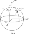
- Figure 4 shows a diagram of a representation 452 of the Earth including an interposed ECEF coordinate system 400 and an ENU coordinate system 301 relative to a representation of the mobile device 100.
- the ECEF coordinate system includes orthogonal axes 454A, 454B and 454C corresponding to directions X ECEF , Y ECEF and Z ECEF , respectively.
- position, velocity and acceleration or other motion data for the mobile device 100 can be defined in terms of both the X ECEF , Y ECEF and Z ECEF directions of the ECEF coordination system 400 as well as the East (E), North (N) and Up (U) directions of the ENU coordinate system 301.
- the Up direction can be defined as the direction opposing gravity (G) or as a ray originating from the geometric center of Earth, while East and North can be defined in terms of magnetic North or geometric (or “true”) North.
- the direction, velocity, acceleration or other motion data of or concerning the mobile device 100 also can be represented or determined in terms of a mobile-device-centric Right, Course-Over-Ground, and Up (RCU) coordinate system.
- the Course-Over-Ground (COG) direction can describe motion along a forward-backward axis along an imaginary horizontal plane on which the mobile device 100 is moving at a point in time
- the Right (R) direction can describe lateral motion along a right-left axis perpendicular to the forward-backward axis on the horizontal plane
- the Up (U) direction describes motion along a vertical axis perpendicular to the horizontal plane.
- Figure 3 also shows an example relationship between the IMU coordinate system 300, the ENU coordinate system 301 and an RCU coordinate system 303 (in the example implementation, the direction Up (U) is the same in both the ENU coordinate system 301 and in the RCU coordinate system 303, although this is not required).
- the direction of motion (M) of the mobile device 100 is illustrated as being along the COG direction, which itself can be defined in terms of a global coordinate system as described above.
- the motion vector M can be described in terms of two or more of the COG, Right (R) and Up (U) directions, or in terms of another coordinate system.
- the motion direction M can be estimated or defined in terms of the orientation direction O rotated by an alignment (or "misalignment") angle ⁇ .
- the orientation direction O describes the orientation or heading of the mobile device 100 itself.
- the orientation direction O can be determined by the mobile device 100 through an analysis of linear acceleration measurements, angular acceleration measurements, rotation measurements, magnetic field measurements, or a combination of such measurements or other measurements, obtained by the sensors of the sensor suite 134.
- the direction of gravity (G) can be estimated by analyzing the acceleration data measured by the accelerometers 236A, 236B and 236C.
- the processor 120 determines that the direction corresponding to the strongest identified acceleration is the direction of gravity.
- the processor 120 can determine the direction of magnetic North using the magnetometers 242A, 242B and 242C. Based on the identified directions of gravity or magnetic North, the mobile device 100 can determine the orientation direction O. As described above, the orientation direction O can be rotated or transformed into a variety of suitable and convenient coordinate systems for describing the COG or motion vector M.
- the alignment angle ⁇ describes the discrepancy between the orientation direction O and the motion direction M.
- the orientation O of the mobile device 100 may not be aligned with the person's direction of motion M.
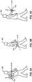
- Figure 5A shows an example scenario in which the mobile device 100 is being carried in a person's 560 backpack
- Figure 5B shows an example scenario in which the mobile device 100 is being carried in the person's 560 side pants pocket
- Figure 5C shows an example scenario in which the mobile device 100 is being carried in the person's 560 hand.
- the orientation O of the mobile device 100 changes relative to the person and relative to the Earth depending on the location of the mobile device 100 on the person as well as depending on the person's motion. For example, as the mobile device 100 moves, turns, swings, rocks, or pivots relative to the direction of motion M of the person carrying the mobile device 100, the alignment angle ⁇ changes.
- the memory 132 includes executable code, instructions or software.
- the executable code includes, or can be characterized as, a number of code blocks or modules.
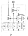
- Figure 6 shows a block diagram of example modules that can be stored in the memory 132 and implemented in conjunction with the processor 120 to perform one or more of the methods or processes described.
- instructions for carrying out the functions of the example modules can be stored in the memory 132 and executed by the processor 120 to perform one or more of the methods described.
- a step detection module 662 receives motion information from the sensor suite 134 including one or both of the step tracker 244 (if present) or from, for example, linear accelerometers 236 or gyroscopes 240. Such motion information also can be provided directly or indirectly to an orientation determination module 664 and a motion direction estimation module 666.
- the step detection module 662 analyzes the motion information from the step tracker 244, the accelerometers 236 or other ones of the sensors in the sensor suite 134 to detect steps taken by the person carrying the mobile device 100. For example, the step detection module 662 can analyze the motion information to identify motion patterns or signatures corresponding to human motion, which it can then use to identify a type of motion or "use case.” For example, the step detection module 662 may determine based on the identified motion information that the person is walking, jogging, running or stair climbing.
- the step detection module 662 also can determine, track or record other step information such as, for example, step lengths, step durations, a running count of steps, or accelerations, velocities, or rotations corresponding to steps (also referred to herein collectively as "step data").
- the orientation determination module 664 determines the orientation direction O through an analysis of linear acceleration measurements, angular acceleration measurements, magnetic field measurements, or a combination of such measurements or sensor data, obtained by the sensors of the sensor suite 134.
- the direction of gravity G can be estimated by analyzing the acceleration data measured by the accelerometers 236A, 236B and 236C.
- the orientation determination module 664 determines that the direction corresponding to the strongest identified acceleration is the direction of gravity G (whether the strongest acceleration is identified by the accelerometers 236 or sensor suite 134 itself prior to being input to the orientation determination module 664, or whether identified by the orientation determination module 664 itself or another module in conjunction with the processor 120 based on the acceleration data received from the accelerometers 236 or other sensors of the sensor suite 134). Additionally or alternatively, the orientation determination module 664 can similarly determine the direction of magnetic North using the magnetometers 242A, 242B and 242C. Based on the identified directions of gravity G or magnetic North N, the orientation determination module 664 determines the orientation O.
- the orientation O can be rotated or transformed into one or more of a variety of suitable and convenient coordinate systems for describing the motion vector M.
- the orientation determination module 664 can provide the orientation O of the mobile device 100 in an ECEF, ENU or geodetic coordinate system.
- the orientation O can be computed (or "estimated” or "determined") on a continuous or periodic basis and may thus be described, stored or tracked as a time-varying signal.
- the motion direction estimation module 666 receives the orientation O from the orientation determination module 664 and computes the motion vector M based on the orientation O, including, in some implementations, present and past values of the orientation O or past values of the motion vector M. In some implementations, the motion direction estimation module 666 also receives sensor data directly from the sensor suite 134 and uses such sensor data, or information derived from such sensor data, to compute the motion vector M. For example, the motion direction estimation module 666 can determine the motion vector M based on the orientation O and the acceleration data or other sensor data measured by the accelerometers 236. Additionally or alternatively, in some implementations, the motion direction estimation module 666 can determine the motion vector M based on the orientation O and the rotation data or other sensor data measured by the gyroscopes 240, or sensor data measured by other sensors.
- the motion direction estimation module 666 also can receive present and past values of the alignment angle ⁇ from an alignment angle computation module 668, which can be configured to determine the alignment angle ⁇ from the orientation O as well as sensor data or other motion information obtained from the sensor suite 134.
- the motion direction estimation module 666 determines the motion vector M based at least partially on the alignment angle ⁇ received from the alignment angle computation module 668.
- the alignment angle computation module 668 determines the alignment angle ⁇ based at least partially on the motion vector M received from the motion direction estimation module 666. That is, once the orientation O and either of the alignment angle ⁇ or the motion vector M is determined, the other one of the alignment angle ⁇ or the motion vector M can be readily calculated by definition.
- calibration data can be received via the network interface 114 and processed by a calibration module 670, which then passes calibration data to the motion direction estimation module 666 to refine, revise or otherwise correct the motion vector M. Additionally or alternatively, in some implementations, the calibration module 670 can receive other calibration data, such as over a cellular or Wi-Fi connection, when enabled.
- the estimated motion direction or motion vector M can be output from or generated by the motion direction estimation module 666 in any suitable coordinate system such as the ECEF and ENU coordinate systems described above.
- the motion direction estimation module 666 outputs an estimated motion vector M in terms of a true or magnetic North direction component and an East direction component.
- the estimated motion vector M also can be represented in terms of an Up direction component.
- the Up component is neglected and so the estimated motion vector M can be simplified or approximated to a COG motion vector as described above.
- the motion direction estimation module 666 receives step data from the step detection module 662 and computes the motion vector M based on the step data. For example, the motion direction estimation module 666 can use the step data to more accurately calculate or estimate the true motion vector M by canceling out periodic acceleration components associated with typical human motion, such as periodic accelerations associated with walking, jogging, running or stair climbing. For example, in typical human motion, the directions of motion and acceleration change within a given step and from one step to the next consecutive step as a result of the natural biomechanics of bipedal human motion.
- a walking person's gait also has motion and acceleration components that change vertically up and down and transversely forward and backward within each individual step's duration. For example, as a person takes a step forward, the person's center of gravity moves up during a first portion of the step and down during a second portion of the step.
- lateral right/left (also referred to as “sideways”) acceleration components generally cycle with a two-step period while transverse forward/backward and vertical up/down acceleration components cycle with a one-step period.
- the motion direction estimation module 666 (or in some other implementations, the step detection module 662) can leverage the information about the relationship between steps and corresponding periodic components of lateral right/left, transverse forward/backward, and vertical up/down (for example, Right, COG, and Up in an RCU coordinate system) acceleration components to isolate the COG component of the motion vector M, which can then be transformed to a global coordinate system.
- the motion direction estimation module 666 stores and analyzes the acceleration data received from the sensor suite 134 in, for example, the memory 132, over a number of consecutive steps (for example, 2, 4, 6, 8, 10 or more consecutive steps).
- the motion direction estimation module 666 can substantially or approximately cancel out the lateral acceleration components of the person's motion by summing the acceleration components (for example, the acceleration components obtained by the accelerometers 236) with one-step-shifted versions of themselves.
- the motion direction estimation module 666 can substantially or approximately cancel out the forward/backward and vertical acceleration components of the person's motion by summing the acceleration components (for example, the acceleration components obtained by the accelerometers 236) with half-step-shifted versions of themselves.
- the mobile device 100 is not carried or otherwise positioned at or near a central location of the carrying user's body during motion. Additionally, in many use cases, the mobile device 100 may shift orientation or otherwise move relative to the user's body during motion. In some such use cases, there may be asymmetric or non-periodic lateral, transverse or vertical acceleration components not associated with steps or with true course-over-ground motion.
- the motion direction estimation module 666 can further suppress or cancel these asymmetric acceleration components by leveraging the relationship between the transverse forward/backward acceleration and the vertical acceleration components. For example, when the forward/ backward and vertical acceleration components are viewed as time-varying periodic signals (where the period is equivalent to one step), a correlation can generally be observed between them.
- the vertical acceleration signal and the forward/backward signal are offset in phase by a characteristic amount that may be empirically determined. For example, when a typical person is walking, the vertical acceleration and forward/backward acceleration components are offset by approximately one-quarter of one step (or "90 degrees").
- the motion direction estimation module 666 can substantially or approximately cancel out the asymmetric components of the acceleration by leveraging the known or expected correlation (for example, the phase offset) between the forward/backward and vertical acceleration components.
- the phase offset between the vertical acceleration and forward/backward acceleration components can change based on where and how the mobile device 100 is being carried during motion; that is, based on a particular use case.
- the phase offset or other parameters or characteristics of motion can change based on whether the mobile device 100 is being carried in a hand swinging forward and backward as the person walks, being carried out in front (for example, while the user is viewing the display 104 or otherwise interacting with the mobile device), being held at the person's ear while the person is using the mobile device 100 as a telephone, or being carried in the person's pocket, purse, or pack.
- Each of these scenarios also may be considered a particular use case.
- the phase offset or other parameters or characteristics may also change based on a change in speed, gait or cadence (for example, from walking to jogging to running). Each of these scenarios also may be considered a particular use case.
- the motion direction estimation module 666 identifies a use case based on an observed correlation of the acceleration components over a number of steps (for example, 2, 4, 6, 8, 10 or more steps) or, in some other implementation, over some duration of time. In some such implementations, after a use case is identified, the motion direction estimation module 666 then adjusts the phase offset or other parameters (for example, a window of time or number of steps within which to track and correlate acceleration data) to more accurately estimate the motion vector M.
- the phase offset or other parameters for example, a window of time or number of steps within which to track and correlate acceleration data
- the motion direction estimation module 666 analyzes the orientation O and the remaining acceleration components to estimate, calculate or otherwise determine and output the motion vector M. For example, in some implementations, the motion direction estimation module 666 performs an eigenvector analysis, and particularly, an eigen-decomposition on the remaining acceleration components.
- an eigen-decomposition can be used to determine two horizontal (for example, relative to the surface of the Earth) eigenvectors e 1 and e 2 , each of which corresponds to an orthogonal directional axis along which COG motion occurs.
- the motion direction estimation module 666 selects the directional axis corresponding to the horizontal eigenvector having the larger respective eigenvalue as the dominant axis of motion (e.g., a forward-backward or COG direction). In some situations or applications, there may be some ambiguity in the resolved dominant axis of motion.
- the motion direction estimation module 666 further refines the motion vector M based on other sensor data such as that measured from the gyroscopes 240 and magnetometers 242.
- a reliability metric computation module 672 calculates a reliability metric for the estimated motion vector M.
- the reliability metric indicates a measure of certainty in the estimated motion vector M.
- the reliability metric can be calculated based on one or more techniques.
- a first reliability metric R 1 can be based on a process used to estimate the motion vector M itself. For example, as described above, the motion direction estimation module 666 may perform an eigen-decomposition to determine two horizontal eigenvectors e 1 and e 2 , each of which corresponds to an orthogonal directional axis along which motion occurs.
- the directional axis corresponding to the horizontal eigenvector having the larger respective eigenvalue can be selected as the dominant axis of motion (for example, a forward-backward direction).
- a ratio of this larger eigenvalue (for example, that corresponding to e 1 ) to the smaller eigenvalue (for example, that corresponding to e 2 ) can provide a first reliability metric R 1 ; that is, a measure of certainty that the direction of motion is along the first eigenvector e 1 .
- the reliability metric computation module 672 calculates a second reliability metric R 2 by analyzing the estimated motion vector signal M over a number of steps or over a period of time. For example, if the direction of the estimated motion vector M remains relatively constant or consistent over the period, then a second reliability metric R 2 can be generated that indicates certainty in the current estimated motion vector M. Contrarily, if the estimated motion direction M is widely varying or inconsistent over the period, then the second reliability metric R 2 can indicate uncertainty or unreliability in the current estimated motion vector M. Various intermediate values also are possible; that is, the value of the second reliability metric R 2 can be proportional to the consistency of the estimated motion vector M over a number of steps or a duration of time.
- the reliability metric computation module 672 performs various calculations to quantify a device stability as a third reliability metric R 3 .
- the device stability can reflect changes in the orientation direction O over time as measured by one or more of the accelerometers 236, gyroscopes 240 or magnetometers 242.
- a value of the third reliability metric R 3 can be determined that is proportional to the stability of the mobile device 100 over a number of steps or a duration of time, and in some such implementations, more directly the stability of the orientation O over a number of steps or a duration of time.
- the determination of the stability of the orientation O includes determining a horizontal component of an instantaneous acceleration, as for example, determined by the motion direction estimation module 666 from acceleration data obtained by the accelerometers 236. Additionally, the determination of the stability of the orientation O also can include determining a vertical component of an instantaneous acceleration, as for example, determined by the motion direction estimation module 666 from acceleration data obtained by the accelerometers 236. In some implementations, the determination of the stability of the orientation O also includes smoothing one or both of the horizontal component and the vertical component of the instantaneous acceleration. For example, the smoothing can include or involve applying a moving average filter to the instantaneous acceleration data over a number of steps or a duration of time.
- the determination of the stability of the orientation O also includes determining a rate of change of the norm of the difference of the smoothed horizontal component from one sample to the next sample (for example, from one step to the next).
- the determination of the stability of the orientation O also can include determining a rate of change of the norm of the difference of the smoothed vertical component from one sample to the next sample (for example, from one step to the next).
- the determination of the stability of the orientation O further includes comparing the rate of change of the smoothed horizontal component of the instantaneous acceleration to one or more horizontal threshold values to obtain a horizontal reliability value.
- the rate of change of the smoothed vertical component of the instantaneous acceleration also can be compared to one or more vertical threshold values to obtain a vertical reliability value.
- the horizontal and vertical reliability values can then be summed or otherwise combined to determine the third reliability metric R 3 .
- the third reliability metric R 3 can include a first horizontal reliability value
- the horizontal acceleration component is above a second horizontal reliability threshold
- the third reliability metric R 3 can include a second horizontal reliability value
- the third reliability metric R 3 can include a first vertical reliability value
- the third reliability metric R 3 can include a second vertical reliability value
- determining a stability of the mobile device also can include determining a rate of rotation, or a change in a rate of rotation, of the mobile device around one or more axes of rotation.
- the gyroscopes 240 can measure such rotation data around the axes of the mobile device coordinate system 300 or another coordinate system.
- determining the device stability further includes smoothing the one or more determined rates of rotation (or changes in rates of rotation) over a number of steps or a duration of time (for example, by a moving average filter).
- the determination of the stability of the orientation O further includes comparing the respective smoothed rates of rotation or changes in rates of rotation to one or more respective threshold values to obtain respective axis-of-rotation reliability values.
- the reliability values for each of the axes of rotation can then be summed or otherwise combined to determine the third reliability metric R 3 .
- one or more reliability metrics are combined by the reliability metric computation module 672 to calculate or generate a combined (also referred to herein as an "overall” or “composite") reliability metric R T for the estimated motion vector M.
- the reliability metric computation module 672 sums two or more of the reliability metrics R 1 , R 2 and R 3 described above.
- the reliability metric computation module 672 multiplies each of one or more of the reliability metrics R 1 , R 2 and R 3 by respective weights W 1 , W 2 and W 3 prior to summation or other combination.
- the weights W 1 , W 2 and W 3 are previously determined (for example, empirically) constants. In some other implementations, the reliability metric computation module 672 calculates the weights W 1 , W 2 and W 3 as functions of various parameters.
- Figure 7 is a flow diagram illustrating an example process 700 for calculating a reliability metric for determining a measure of reliability in an estimated motion vector M.
- the process 700 begins at 701 with obtaining acceleration data for a mobile device (for example, the mobile device 100) in each of one or more directions.
- the first linear accelerometer 236A can measure linear acceleration data along the first axis 338A of the mobile device coordinate system 300 of Figure 3
- the second linear accelerometer 236B can measure linear acceleration data along the second orthogonal axis 338B
- the third linear accelerometer 236C can measure linear acceleration data along the third orthogonal axis 338C.
- the acceleration data also can include angular acceleration data from, for example, the gyroscopes 240.
- the process 700 proceeds at 703 with estimating a motion direction of the mobile device relative to a global coordinate system based at least in part on the acceleration data obtained at 701.
- the motion direction estimation module 666 can analyze the orientation O and the remaining acceleration components after cancelling the periodic and asymmetric components to estimate, calculate or otherwise determine and output the motion vector M.
- the motion vector M can be generated in any suitable coordinate system such as, for example, the ECEF coordinate system 400 or the ENU coordinate system 301 described above.
- the process 700 proceeds at 705 with estimating one or more reliability metrics.
- Each reliability metric indicates a measure of certainty or estimated accuracy in the estimated motion vector M.
- at least two reliability metrics are determined.
- the reliability metric computation module 672 can calculate a first reliability metric R 1 based on a process used to estimate the motion vector M itself.
- the motion direction estimation module 666 can perform an eigen-decomposition to determine two horizontal eigenvectors e 1 and e 2 , each of which corresponds to an orthogonal directional axis along which motion occurs.
- the directional axis corresponding to the horizontal eigenvector having the larger respective eigenvalue can be selected as the dominant axis of motion (for example, a forward-backward direction).
- the first reliability metric R 1 can be, or can be based on, the ratio of this larger eigenvalue (for example, that corresponding to e 1 ) to the smaller eigenvalue (for example, that corresponding to e 2 ); that is, the first reliability metric R 1 indicates a measure of certainty that the direction of motion is along the first eigenvector e 1 .
- the reliability metric computation module 672 can calculate a second reliability metric R 2 based on a consistency of the estimated motion vector signal M over a number of steps or over a period of time. For example, if the direction of the estimated motion vector M remains relatively constant or consistent over the period, then a second reliability metric R 2 can be generated that indicates certainty in the current estimated motion vector M. Contrarily, if the estimated motion direction M is widely varying or inconsistent over the period, then the second reliability metric R 2 can indicate uncertainty or unreliability in the current estimated motion vector M. As described above, various intermediate values also are possible such that the value of the second reliability metric R 2 can be proportional to the consistency of the estimated motion vector M over a number of steps or a duration of time.
- the reliability metric computation module 672 also can, in some implementations, perform various calculations to calculate a third reliability metric R 3 based on a quantification of the stability of the device.
- the device stability can reflect changes in the orientation direction O over time as measured by one or more of the accelerometers 236, gyroscopes 240 or magnetometers 242.
- a value of the third reliability metric R 3 can be proportional to the stability of the mobile device 100 over a number of steps or a duration of time, and in some such implementations, more directly the stability of the orientation O over a number of steps or a duration of time.
- the process 700 proceeds at 707 with summing or otherwise combining the one or more reliability metrics, such as the reliability metrics R 1 , R 2 and R 3 described above, to calculate or generate a composite reliability metric R T for the estimated motion vector M.
- the reliability metric computation module 672 sums two or more of the reliability metrics R 1 , R 2 and R 3 described above. Additionally, in some implementations, the reliability metric computation module 672 multiplies each of one or more of the reliability metrics R 1 , R 2 and R 3 by respective weights W 1 , W 2 and W 3 prior to summation or other combination.
- the motion direction M estimated at 703 is only used when the composite reliability metric R T determined at 707 is above a threshold. In some such implementations, when the composite reliability metric R T is not above a threshold, then the mobile device turns on or otherwise enables the network interface 114 so that calibration data can be received from, for example, a GPS or other SNS system to refine the motion vector M and to reduce the uncertainty.
- the process 700 is performed (or "repeated") on a step-by-step basis. In some other implementations, the process 700 is performed periodically, for example, every 2, 4, 6, 8, 10 or more steps, or at other suitable intervals including intervals of time.
- the motion direction estimation module 666 and the reliability metric computation module 672 utilize present or past acceleration data, present or past orientation data, present or past rotation data, or previously estimated values of the motion vector M.
- one or more of the blocks or steps of the process 700 can be performed using data within a moving window of time.
- one or more of the blocks or steps of the process 700 can be performed on a step-by-step basis using data from the most recent 6 steps or another suitable number of steps or interval of time.
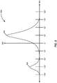
- the motion direction estimation module 666 tracks or stores the eigenvalue data signal (for example, e 1 ) corresponding to the eigenvalue associated with the eigenvector determined to be associated with the forward-backward axis of motion. In some such implementations, the motion direction estimation module 666 fits the data recorded for a number of steps (for example, 2, 4, 6, 8, 10, 50, 100 or more steps) to a bimodal probability distribution.
- the motion direction estimation module 666 allows the eigenvalue data to fit a bimodal distribution knowing that either the positive or negative direction is the true direction. This is in contrast to some conventional methods that may fit of force the data to a normal distribution and take the average of all the samples of the eigenvalue e 1 as the direction of motion.
- Figure 8 shows an example bimodal probability distribution 880.
- the vertical axis 882 represents the number or density of eigenvalues and the horizontal axis 884 represents the direction in degrees as measured from magnetic North.
- a first higher peak (or "mode") 886 of the bimodal probability distribution 880 corresponds to a forward direction along the first horizontal directional axis associated with the first eigenvector e 1
- a second lower peak (or "mode") 888 of the bimodal probability distribution 880 corresponds to a backwards direction (opposite the forwards direction) along the first horizontal directional axis associated with the first eigenvector e 1 .
- the first peak 886 corresponds to a forward direction that is 45 degrees East of magnetic North and the second peak 888 corresponds to a backwards direction that is 180 degrees from the forward direction; that is, 135 degrees West (or -135 degrees East) of magnetic North.
- the motion direction estimation module 666 would select 45 degrees from magnetic North as the direction of motion M.
- the direction of motion may be determined to be -10 degrees from North-clearly not an accurate estimation-resulting from forcing the data to a normal distribution or single-peaked model.
- the motion direction estimation module 666 compares the relative heights of the first peak 886 and the second peak 888 and selects the direction corresponding to the highest one of the peaks (in this case the forward direction corresponding to the first peak 886) as the direction of the motion vector M.
- the reliability metric computation module 672 calculates a reliability metric R 4 based on a ratio of the height of the first peak 886 to the height of the second peak 888. For example, a larger ratio may indicate a more reliable estimation of the motion direction M.
- the reliability metric computation module 672 analyzes the widths of the first peak 886 and the second peak 888 to estimate a reliability metric R 5 for the selected direction of the motion vector M.
- one or both of the reliability metrics R 4 and R 5 can be combined with one or more of the reliability metrics R 1 , R 2 and R 3 described above to generate the composite reliability metric R T .
- Figure 9 is a flow diagram illustrating an example process 900 for determining a direction of motion M.
- the process 900 begins at 901 with obtaining acceleration data for a mobile device (for example, the mobile device 100) in each of one or more directions.
- the first linear accelerometer 236A can measure linear acceleration data along the first axis 338A of the mobile device coordinate system 300 of Figure 3
- the second linear accelerometer 236B can measure linear acceleration data along the second orthogonal axis 338B
- the third linear accelerometer 236C can measure linear acceleration data along the third orthogonal axis 338C.
- the acceleration data also can include angular acceleration data from, for example, the gyroscopes 240.
- the process 900 proceeds at 903 with determining an axis of motion of the mobile device relative to a global coordinate system based at least in part on the acceleration data obtained at 901.
- the motion direction estimation module 666 can analyze the orientation O and the remaining acceleration components after cancelling the periodic and asymmetric components to estimate, calculate or otherwise determine the primary or dominant axis of motion.
- an eigen-decomposition can be used to determine two horizontal (for example, relative to the surface of the Earth) eigenvectors e 1 and e 2 , each of which corresponds to an orthogonal directional axis along which COG motion occurs.
- the motion direction estimation module 666 selects the directional axis corresponding to the horizontal eigenvector having the larger respective eigenvalue (for example, e 1 ) as the dominant axis of motion (e.g., a forward-backward direction).
- the process 900 proceeds at 905 with determining a direction of motion along the axis of motion determined at 903.
- the motion direction estimation module 666 tracks or stores the eigenvalue data signal (for example, e 1 ) over a number of steps or a duration of time.
- the motion direction estimation module 666 fits the eigenvalue data recorded for a number of steps (for example, 2, 4, 6, 8, 10, 50, 100 or more steps) to a bimodal probability distribution, such as, for example, the bimodal probability distribution 880 of Figure 8 .
- a first higher peak 886 of the bimodal probability distribution 880 can correspond to a forward direction along the first horizontal directional axis associated with the first eigenvector e 1
- a second lower peak 888 of the bimodal probability distribution 880 can correspond to a backwards direction (opposite the forwards direction) along the first horizontal directional axis associated with the first eigenvector e 1
- the motion direction estimation module 666 compares the relative heights of the first peak 886 and the second peak 888 and selects the direction corresponding to the highest one of the peaks as the direction of the motion M.
- the process 900 is performed on a step-by-step basis. In some other implementations, the process 900 is performed periodically, for example, every 2, 4, 6, 8, 10 or more steps, or at other suitable intervals including intervals of time.
- the motion direction estimation module 666 and the reliability metric computation module 672 utilize present or past acceleration data, present or past orientation data, present or past rotation data, or previously estimated values of the motion vector M.
- one or more of the blocks or steps of the process 900 can be performed using data within a moving window of time.
- one or more of the blocks or steps of the process 900 can be performed on a step-by-step basis using data from the most recent 6 steps or another suitable number of steps or interval of time.
- the motion direction estimation module 666 identifies a likely use case; that is, a likely manner in which the mobile device is being carried by the pedestrian or a manner in which the pedestrian is moving.
- the motion direction estimation module 666 can use any of the linear acceleration, angular acceleration, or other rotation or orientation data to determine a likely use case.
- some example pedestrian use cases include walking, jogging, running or stair climbing.
- linear acceleration data obtained by the linear accelerometers 236 may be used to determine that a user is running versus walking.
- a determined phase offset between the vertical and horizontal components of acceleration also can be used to determine whether a user is, for example, running versus walking.
- Some use cases also may reflect where or how the mobile device 100 is positioned or being carried during motion. For example, such use cases reflect whether the mobile device 100 is being carried in a hand swinging forward and backward as the person walks, being carried out in front (for example, while the user is viewing the display 104 or otherwise interacting with the mobile device), being held at the person's ear while the person is using the mobile device 100 as a telephone, or being carried in the person's pocket, purse, or pack.
- Use cases also can be determined based on a combination of the aforementioned use cases. For example, a use case in which a person is jogging while talking with the mobile device at her ear.
- the motion direction estimation module 666 also can use non-movement related information to classify a current use case of the mobile device or person. For example, based on a certain tilt of the mobile device 100 (as determined from rotation data or magnetic data from the gyroscopes 240 or magnetometers 242, respectively), or whether a call is initiated, the motion direction estimation module 666 can determine that the mobile device 100 is being held near the person's ear.
- the motion direction estimation module 666 can then be selected and optimized to obtain an accurate estimated motion direction M.
- the motion direction estimation module 666 identifies the use case by matching the acceleration, rotation or orientation data determined from the sensor suite 134 to acceleration, rotation or orientation data corresponding to predetermined use cases stored in a use case database in, for example, the memory 132.
- the motion direction estimation module 666 can retrieve a set of predetermined parameters stored or linked with the identified use case in the memory 132.
- the motion direction estimation module 666 does not match data with that of predetermined use cases.
- the motion direction estimation module 666 can determine a use case and subsequently select or otherwise optimize existing parameters for that specific use case. The motion direction estimation module can then use the selected parameters to estimate the motion direction M.
- Figure 10 is a flow diagram illustrating an example process 1000 for selecting one or more parameters to determine a direction of motion M.
- the process 1000 begins at 1001 with obtaining acceleration data for a mobile device (for example, the mobile device 100) in each of one or more directions.
- the first linear accelerometer 236A can measure linear acceleration data along the first axis 338A of the mobile device coordinate system 300 of Figure 3
- the second linear accelerometer 236B can measure linear acceleration data along the second orthogonal axis 338B
- the third linear accelerometer 236C can measure linear acceleration data along the third orthogonal axis 338C.
- the acceleration data also can include angular acceleration data from, for example, the gyroscopes 240.
- the process 1000 proceeds at 1003 with identifying a use case for the mobile device based at least in part on the acceleration data.
- the motion direction estimation module 666 can identify a use case based on the linear acceleration data obtained from linear accelerometers 236. Additionally or alternatively, in some other implementations, the use case also can be determined based on other angular acceleration data, rotation data or orientation data.
- the motion direction estimation module 666 identifies the use case by matching the acceleration, rotation or orientation data determined from the sensor suite 134 to acceleration, rotation or orientation data corresponding to predetermined use cases stored in a use case database in, for example, the memory 132. In some other implementations, the motion direction estimation module 666 does not match data with that of predetermined use cases; rather, the motion direction estimation module 666 identifies or determines one or more use case characteristics to more precisely determine the actual use case of the user.
- the process 1000 then proceeds at 1005 with selecting one or optimizing one or more parameters for use by the motion direction estimation module 666 is estimating a motion direction M.
- the motion direction estimation module 666 matches acceleration data with that of predetermined use cases stored in memory, the motion direction estimation module 666 can retrieve a set of predetermined parameters stored or linked with the identified use case in the memory 132. In some other implementations in which the motion direction estimation module 666 does not perform such a matching, the motion direction estimation module 666 can determine a use case and subsequently select or otherwise optimize existing parameters for that specific use case.
- the process then proceeds at 1007 with using the selected parameters to estimate the motion direction M relative to a global coordinate system as, for example, described above.
- the estimation of the motion direction of the mobile device can be based at least in part on the acceleration data obtained at 1001 and one or more of the averaging window size, smoothing mechanism, and the presumed phase offset between the forward and vertical acceleration signals.
- the device may selectively choose to turn on and make use of gyroscope measurements for high-motion use cases.
- the motion direction estimation module 666 can analyze the orientation O and the remaining acceleration components after cancelling the periodic and asymmetric components to estimate, calculate or otherwise determine and output the motion vector M.
- the motion vector M can be generated in any suitable coordinate system such as, for example, the ECEF coordinate system 400 or the ENU coordinate system 301 described above.
- the process 1000 is performed on a step-by-step basis. In some other implementations, the process 1000 is performed periodically, for example, every 2, 4, 6, 8, 10 or more steps, or at other suitable intervals including intervals of time.
- the motion direction estimation module 666 and the reliability metric computation module 672 utilize present or past acceleration data, present or past orientation data, present or past rotation data, or previously estimated values of the motion vector M.
- one or more of the blocks or steps of the process 1000 can be performed using data within a moving window of time.
- one or more of the blocks or steps of the process 1000 can be performed on a step-by-step basis using data from the most recent 6 steps or another suitable number of steps or interval of time.
- Figure 11 shows another block diagram of example modules that can be stored in the memory 132 and implemented in conjunction with the processor 120 to perform one or more of the methods or processes described.
- the example modules of Figure 11 are the same or similar to those described with reference to Figure 6 with an exception being that the memory 132 stores a plurality of motion direction estimation modules 666 a -666 n that, when executed by the processor 120, perform in parallel to generate a respective plurality of estimated motion directions M a -M n .
- the memory 132 may include 2, 3, 4, 5 or more parallel-running motion direction estimation modules 666 a -666 n .
- each of the motion direction estimation modules 666 a -666 n can use a different set of one or more parameters based on a predefined respective use case.
- a first motion direction estimation module 666 a can be set to use or select a set of parameters optimized for a use case in which the mobile device is in the person's hand and being viewed by the person (for example, held at chest level in front of the person).
- a second motion direction estimation module 666 b can be set to use or select a second different set of parameters optimized for a use case in which the mobile device is in the person's hand and swinging along with the person's arm as the person walks or runs.
- a third motion direction estimation module 666 c can be set to use or select a third different set of parameters optimized for a use case in which the mobile device is in the person's hand and held to the person's ear for communicating.
- a fourth motion direction estimation module 666 d can be set to use or select a fourth different set of parameters optimized for a use case in which the mobile device is in the person's pocket or handbag.
- the parameters that can be used or tuned can include, for example, the length of an averaging window, a smoothing mechanism, a phase difference used to identify correlations between horizontal and vertical acceleration components, or whether to always average across a pair of consecutive steps in an attempt to cancel effects of left-foot/right-foot asymmetry. In this way, rather than detecting a use case and subsequently configuring parameters, a plurality of motion direction estimations modules can run in parallel, where each motion direction estimation module is configured with a different set of parameters for a particular corresponding use case.
- the memory 132 also stores a plurality of reliability metric computation module 672 a -672 n that, when executed by the processor 120, perform in parallel to generate a plurality of reliability metrics R a -R n for the respective estimated motion directions M a -M n generated by the respective motion direction estimation modules 666 a -666 n .
- a selection module 1190 selects the one of the estimated motion directions M a -M n having the highest respective one of the reliability metrics R a -R n as the estimated motion direction M of the person.
- the one of the motion directions M a -M n having the highest respective one of the reliability metrics R a -R n is selected because the use case associated with the one of the motion direction estimation modules 666 a -666 n that produced the selected motion direction likely matches, or at least is the best match for, the actual use case of the person carrying the mobile device.
- the memory 132 also can store a comparator 1192 that, when executed by the processor 120, performs to compare each of the reliability metrics R a -R n to a threshold, or in some other implementations, performs to compare the selected one of the reliability metrics R a -R n to the threshold. In some implementations, if none of the reliability metrics R a -R n are above a threshold, then the comparator 1192 sends a signal to the selection module 1190 to instruct the selection module to select the one of the motion directions M a -M n corresponding to the motion direction selected for the previous step (or other previous analysis point).
- the comparator 1192 sends a signal to the selection module 1190 to instruct the selection module to select the one of the motion directions M a -M n estimated by a motion direction estimation module that uses a default set of parameters.
- the selection module 1190 can select two or more of the most reliable estimated motion directions M a -M n and average or otherwise combine them, and in some implementations with different weights, to obtain a single composite estimated motion direction M.
- Figure 12 is a flow diagram illustrating an example process 1200 for determining a direction of motion M.
- the process 1200 begins at 1201 with obtaining acceleration data for a mobile device (for example, the mobile device 100) in each of one or more directions.
- the first linear accelerometer 236A can measure linear acceleration data along the first axis 338A of the mobile device coordinate system 300 of Figure 3
- the second linear accelerometer 236B can measure linear acceleration data along the second orthogonal axis 338B
- the third linear accelerometer 236C can measure linear acceleration data along the third orthogonal axis 338C.
- the acceleration data also can include angular acceleration data from, for example, the gyroscopes 240.
- the process 1200 proceeds at 1203 with estimating a plurality of motion directions M a -M n for the mobile device based at least in part on the acceleration data obtained at 1201.
- the motion direction estimation modules 666 a -666 n can estimate the plurality of motion directions M a -M n .
- each of the motion direction estimation modules 666 1 -666 n can use a different set of one or more parameters based on a predefined respective use case.
- each of the motion direction estimation modules 666 a -666 n can analyze the orientation O and the remaining acceleration components after cancelling the periodic and asymmetric components to estimate, calculate or otherwise determine and output the motion directions M a -M n .
- the motion directions M 1 -M n can be generated in any suitable coordinate system such as, for example, the ECEF coordinate system 400 or the ENU coordinate system 301 described above.
- each of the reliability metrics R a -R n indicates a measure of certainty or estimated accuracy in the respective one of the estimated motion directions M 1 -M n .
- each of the reliability metrics R a -R n is itself a combination or composite reliability metric.
- each of the reliability metrics R a -R n can be a combination of some or all of the reliability metrics R 1 , R 2 , R 3 , R 4 and R 5 .
- the process 1200 proceeds at 1207 comparing the highest respective one of the reliability metrics R a -R n to a threshold and determining whether the reliability metric is above the threshold.
- the process 1200 proceeds at 1209 with selecting (for example, by the selection module 1190) the respective one of the estimated motion directions M a -M n having the highest one of the reliability metrics R a -R n as the estimated motion direction M of the person.
- the respective one of the motion directions M a -M n is then output at 1213.
- the selection module 1190 also can select two or more of the most reliable estimated motion directions M a -M n and average or otherwise combine them, and in some implementations with different weights, to obtain a single composite estimated motion direction M.
- the process 1200 is performed on a step-by-step basis. In some other implementations, the process 1200 is performed periodically, for example, every 2, 4, 6, 8, 10 or more steps, or at other suitable intervals including intervals of time.
- the motion direction estimation modules 666 a -666 n and the reliability metric computation module 672 a -672 n utilize present or past acceleration data, present or past orientation data, present or past rotation data, or previously estimated values of the motion directions M a -M n .
- one or more of the blocks or steps of the process 1200 can be performed using data within a moving window of time.
- one or more of the blocks or steps of the process 1200 can be performed on a step-by-step basis using data from the most recent 6 steps or another suitable number of steps or interval of time.
- the hardware and data processing apparatus used to implement the various illustrative logics, logical blocks, modules and circuits described in connection with the aspects disclosed herein can be implemented or performed with a general purpose single- or multi-chip processor, a digital signal processor (DSP), an application specific integrated circuit (ASIC), a field programmable gate array (FPGA) or other programmable logic device, discrete gate or transistor logic, discrete hardware components, or any combination thereof designed to perform the functions described herein.
- a general purpose processor can be a microprocessor, or, any conventional processor, controller, microcontroller, or state machine.
- a processor also can be implemented as a combination of computing devices, such as a combination of a DSP and a microprocessor, a plurality of microprocessors, one or more microprocessors in conjunction with a DSP core, or any other such configuration.
- particular steps and methods can be performed by circuitry that is specific to a given function.
- the functions described can be implemented in hardware, digital electronic circuitry, computer software, firmware, including the structures disclosed in this specification and their structural equivalents thereof, or in any combination thereof. Implementations of the subject matter described in this specification also can be implemented as one or more computer programs, i.e., one or more modules of computer program instructions, encoded on a computer storage media for execution by, or to control the operation of, data processing apparatus.
- Computer-readable media includes both computer storage media and communication media including any medium that can be enabled to transfer a computer program from one place to another.
- a storage media can be any available media that can be accessed by a computer.
- such computer-readable media can include RAM, ROM, EEPROM, CD-ROM or other optical disk storage, magnetic disk storage or other magnetic storage devices, or any other medium that can be used to store desired program code in the form of instructions or data structures and that can be accessed by a computer.
- Disk and disc includes compact disc (CD), laser disc, optical disc, digital versatile disc (DVD), floppy disk, and blu-ray disc where disks usually reproduce data magnetically, while discs reproduce data optically with lasers. Combinations of the above also can be included within the scope of computer-readable media. Additionally, the operations of a method or algorithm can reside as one or any combination or set of codes and instructions on a machine readable medium and computer-readable medium, which can be incorporated into a computer program product.
- the terms “upper” and “lower” are sometimes used for ease of describing the figures, and indicate relative positions corresponding to the orientation of the figure on a properly oriented page, and may not reflect the proper orientation of, e.g., an IMOD display element as implemented. Additionally, the conjunction “or” is intended in the inclusive sense where appropriate unless otherwise indicated; that is, the phrase “A or B” is intended to include the possibilities of "A,” “B,” and “A and B.”
Landscapes
- Engineering & Computer Science (AREA)
- General Engineering & Computer Science (AREA)
- Theoretical Computer Science (AREA)
- Physics & Mathematics (AREA)
- General Physics & Mathematics (AREA)
- Radar, Positioning & Navigation (AREA)
- Remote Sensing (AREA)
- Human Computer Interaction (AREA)
- Automation & Control Theory (AREA)
- Navigation (AREA)
- Traffic Control Systems (AREA)
- Telephone Function (AREA)
Claims (15)
- Procédé comprenant :l'obtention (1201) de données d'accélération pour un dispositif mobile dans chacune d'une ou plusieurs directions ;le calcul (1203), par une pluralité de modules d'estimation de direction de mouvement s'exécutant dans le dispositif mobile, d'une pluralité de directions de mouvements estimées respectives concomitantes pour le dispositif mobile dans un système de coordonnées global, chacun de la pluralité de modules d'estimation de direction de mouvement calculant la direction de mouvement estimée correspondante sur la base au moins en partie des données d'accélération passées et courantes et d'un ensemble de paramètres prédéfinis associés à un cas d'utilisation ;la détermination (1205) d'une métrique de fiabilité pour chacune des directions de mouvements estimées, la métrique de fiabilité indiquant une mesure de certitude dans la direction de mouvement estimée ;la comparaison (1207) de chaque métrique de fiabilité pour chacune des directions de mouvements estimées pout identifier la métrique de fiabilité qui indique la plus grande fiabilité ;l'identification (1209) de la direction de mouvement correspondant à la métrique de fiabilité identifiée ; etla génération (1213), comme sortie, d'une direction de mouvement résultante, basée au moins en partie sur la métrique de fiabilité identifiée.
- Procédé selon la revendication 1, dans lequel la génération de la direction de mouvement résultante, basée au moins en partie sur la métrique de fiabilité identifiée, comprend la sélection de la direction de mouvement identifiée en tant que direction de mouvement résultante.
- Procédé selon la revendication 1, comprenant en outre l'identification d'une seconde métrique de fiabilité indiquant une fiabilité maximale suivante et une seconde direction de mouvement identifiée correspondante, dans lequel la génération de la direction de mouvement résultante, basée au moins en partie sur la métrique de fiabilité identifiée, comprend la sélection des deux directions de mouvement identifiées et la combinaison des deux directions de mouvement identifiées pour générer la direction de mouvement résultante.
- Procédé selon l'une quelconque des revendications précédentes, comprenant en outre la comparaison de la métrique de fiabilité identifiée à un seuil, dans lequel la génération de la direction de mouvement résultante, basée au moins en partie sur la métrique de fiabilité identifiée, comprend la sélection de la direction de mouvement identifiée uniquement lorsque la métrique de fiabilité identifiée est supérieure au seuil.
- Procédé selon la revendication 4, dans lequel, lorsque la métrique de fiabilité identifiée est inférieure au seuil, la génération de la direction de mouvement résultante, basée au moins en partie sur la métrique de fiabilité identifiée, comprend la sélection d'une direction de mouvement calculée par un des modules d'estimation de direction de mouvement à partir de laquelle une direction de mouvement immédiatement précédente a été sélectionnée en tant que direction de mouvement résultante.
- Procédé selon la revendication 4, dans lequel, lorsque la métrique de fiabilité identifiée est inférieure au seuil, la génération de la direction de mouvement résultante, basée au moins en partie sur la métrique de fiabilité identifiée, comprend la sélection d'une direction de mouvement calculée par un des modules d'estimation de direction de mouvement qui utilise un ensemble de paramètres par défaut en tant que direction de mouvement résultante.
- Procédé selon l'une quelconque des revendications précédentes, comprenant en outre l'identification d'une orientation du dispositif mobile dans le système de coordonnées global sur la base des données d'accélération ou d'autres données d'orientation, dans lequel, pour chaque module d'estimation de direction de mouvement, le calcul de la direction de mouvement estimée correspondante du dispositif mobile dans le système de coordonnées global est également basé au moins en partie sur l'orientation.
- Procédé selon la revendication 7, dans lequel les données d'orientation incluent l'une ou les deux parmi des données gyroscopiques et des données magnétométriques.
- Procédé selon l'une quelconque des revendications précédentes, comprenant en outre le suivi d'un nombre d'étapes effectuées par une personne portant le dispositif mobile ou à laquelle le dispositif mobile est attaché, dans lequel le procédé est exécuté dans une fenêtre temporelle de mouvement, et dans lequel chaque ensemble prédéfini de paramètres associé à un cas d'utilisation comprend une longueur de fenêtre correspondant à un nombre respectif d'étapes.
- Procédé selon l'une quelconque des revendications précédentes, dans lequel chaque ensemble prédéfini de paramètres associé à un cas d'utilisation comprend un déphasage entre des composantes verticale et horizontale des données d'accélération.
- Dispositif mobile (100) comprenant :un ou plusieurs capteurs (134) configurés pour mesurer des données d'accélération pour le dispositif mobile dans chacune d'une ou plusieurs directions ;un ou plusieurs processeurs (120) ; etune mémoire (132) stockant des données d'accélération passées et courantes et des instructions qui, lorsqu'elles sont exécutées par le ou les processeurs, mettent en oeuvre une pluralité de modules comprenant :une pluralité de modules d'estimation de direction de mouvement configurés pour calculer une pluralité de directions de mouvements estimées respectives concomitantes pour le dispositif mobile dans un système de coordonnées global, chacun de la pluralité de modules d'estimation de direction de mouvement étant configuré pour calculer la direction de mouvement estimée correspondante sur la base au moins en partie des données d'accélération passées et courantes et d'un ensemble de paramètres associés à un cas d'utilisation ;une pluralité de modules de calcul de métrique de fiabilité configurés pour déterminer une pluralité de métriques de fiabilité pour les directions de mouvements estimées respectives, la métrique de fiabilité indiquant une mesure de certitude de la direction de mouvement estimée ; etun module de sélection configuré pour :comparer chaque métrique de fiabilité pour chacune des directions de mouvements estimées pour identifier la métrique de fiabilité qui indique la plus grande fiabilité ;identifier la direction de mouvement correspondant à la métrique de fiabilité identifiée ; etgénérer, comme sortie, une direction de mouvement résultante, basée au moins en partie sur la métrique de fiabilité identifiée.
- Dispositif mobile selon la revendication 11, dans lequel le module de sélection est configuré pour sélectionner la direction de mouvement identifiée en tant que direction de mouvement résultante.
- Dispositif mobile selon la revendication 11, dans lequel le module de sélection est en outre configuré pour identifier une deuxième métrique de fiabilité indiquant une fiabilité maximale suivante et une deuxième direction de mouvement identifiée correspondante, le module de sélection étant configuré pour sélectionner les deux directions de mouvement identifiées et pour combiner les deux directions de mouvement identifiées pour générer la direction de mouvement résultante.
- Dispositif mobile selon l'une quelconque des revendications 11 à 13, comprenant en outre un comparateur configuré pour comparer la métrique de fiabilité identifiée à un seuil, dans lequel le module de sélection est configuré pour sélectionner la direction de mouvement identifiée uniquement lorsque la métrique de fiabilité identifiée est supérieure au seuil.
- Support de stockage tangible lisible par ordinateur, comprenant des instructions non transitoires qui, lorsqu'elles sont exécutées par un ou plusieurs processeurs, sont configurés pour mettre en oeuvre le procédé selon l'une quelconque des revendications 1 à 10.
Applications Claiming Priority (2)
| Application Number | Priority Date | Filing Date | Title |
|---|---|---|---|
| US14/268,973 US20150316577A1 (en) | 2014-05-02 | 2014-05-02 | Motion direction determination and application |
| PCT/US2015/022039 WO2015167695A1 (fr) | 2014-05-02 | 2015-03-23 | Détermination de direction de mouvement et application |
Publications (2)
| Publication Number | Publication Date |
|---|---|
| EP3137969A1 EP3137969A1 (fr) | 2017-03-08 |
| EP3137969B1 true EP3137969B1 (fr) | 2019-01-16 |
Family
ID=52829352
Family Applications (1)
| Application Number | Title | Priority Date | Filing Date |
|---|---|---|---|
| EP15716241.3A Not-in-force EP3137969B1 (fr) | 2014-05-02 | 2015-03-23 | Détermination et application de la direction du mouvement |
Country Status (7)
| Country | Link |
|---|---|
| US (1) | US20150316577A1 (fr) |
| EP (1) | EP3137969B1 (fr) |
| JP (1) | JP2017516091A (fr) |
| KR (1) | KR20160149204A (fr) |
| CN (1) | CN106462234B (fr) |
| BR (1) | BR112016025434A2 (fr) |
| WO (1) | WO2015167695A1 (fr) |
Families Citing this family (12)
| Publication number | Priority date | Publication date | Assignee | Title |
|---|---|---|---|---|
| US9983224B2 (en) | 2014-05-02 | 2018-05-29 | Qualcomm Incorporated | Motion direction determination and application |
| US10281484B2 (en) | 2014-05-02 | 2019-05-07 | Qualcomm Incorporated | Motion direction determination and application |
| KR102172631B1 (ko) * | 2015-04-24 | 2020-11-03 | 삼성전기주식회사 | 디지털 촬영시스템 및 그 제어방법 |
| US10291975B2 (en) * | 2016-09-06 | 2019-05-14 | Apple Inc. | Wireless ear buds |
| CN110319851B (zh) * | 2018-03-30 | 2022-03-01 | 北京百度网讯科技有限公司 | 传感器的校正方法、装置、设备及存储介质 |
| US10901529B2 (en) * | 2018-07-19 | 2021-01-26 | Stmicroelectronics S.R.L. | Double-tap event detection device, system and method |
| CN109163723A (zh) * | 2018-08-16 | 2019-01-08 | 东南大学 | 一种手机在口袋中摆动时的角度测量方法 |
| US11601772B2 (en) | 2018-11-26 | 2023-03-07 | Raytheon Bbn Technologies Corp. | Systems and methods for enhancing attitude awareness in ambiguous environments |
| CN111693041B (zh) * | 2019-03-12 | 2022-03-08 | 腾讯科技(深圳)有限公司 | 方向定位方法、装置及存储介质 |
| US20210192681A1 (en) * | 2019-12-18 | 2021-06-24 | Ati Technologies Ulc | Frame reprojection for virtual reality and augmented reality |
| WO2021237660A1 (fr) * | 2020-05-29 | 2021-12-02 | Beijing Didi Infinity Technology And Development Co., Ltd. | Navigation intérieure |
| WO2024101674A1 (fr) * | 2022-11-11 | 2024-05-16 | 삼성전자주식회사 | Système de détection de direction de mouvement, dispositif électronique porté sur soi et procédé de détection de direction de mouvement dans ledit système et ledit dispositif électronique porté sur soi |
Family Cites Families (22)
| Publication number | Priority date | Publication date | Assignee | Title |
|---|---|---|---|---|
| JP4515497B2 (ja) * | 2005-03-28 | 2010-07-28 | 旭化成エレクトロニクス株式会社 | 進行方向計測装置及び進行方向計測方法 |
| CN100561130C (zh) * | 2006-07-18 | 2009-11-18 | 华南农业大学 | 一种导航定位数据的校正方法 |
| CN101270995A (zh) * | 2007-03-21 | 2008-09-24 | 乐金电子(昆山)电脑有限公司 | 导航系统中移动物体的位置显示更新方法 |
| CN101809409B (zh) * | 2007-09-10 | 2012-06-13 | 三菱电机株式会社 | 导航装置 |
| US8078401B2 (en) * | 2007-09-18 | 2011-12-13 | Honeywell International Inc. | Method of personal navigation using stride vectoring |
| JP2010112854A (ja) * | 2008-11-07 | 2010-05-20 | Panasonic Corp | 歩行者用ナビゲーション装置および歩行者用ナビゲーション装置における移動方向検出方法 |
| KR101267163B1 (ko) * | 2008-11-20 | 2013-05-24 | 아사히 가세이 일렉트로닉스 가부시끼가이샤 | 물리량 계측 장치 및 물리량 계측 방법 |
| JP5051550B2 (ja) * | 2009-02-26 | 2012-10-17 | アイシン・エィ・ダブリュ株式会社 | ナビゲーション装置及びナビゲーション用プログラム |
| GB2469679B (en) * | 2009-04-23 | 2012-05-02 | Imagination Tech Ltd | Object tracking using momentum and acceleration vectors in a motion estimation system |
| JP5402335B2 (ja) * | 2009-07-10 | 2014-01-29 | アイシン・エィ・ダブリュ株式会社 | 信頼度評価装置、信頼度評価方法および信頼度評価プログラム |
| CN102484660B (zh) * | 2010-01-07 | 2014-06-11 | 株式会社东芝 | 移动状态推测装置、方法及程序 |
| CN101944234B (zh) * | 2010-07-23 | 2012-07-25 | 中国科学院研究生院 | 特征迹驱动的多目标跟踪方法及装置 |
| JP2012107992A (ja) * | 2010-11-17 | 2012-06-07 | Sony Corp | 歩行状況検出装置、歩行状況検出方法及び歩行状況検出プログラム |
| KR101759350B1 (ko) * | 2010-11-25 | 2017-07-18 | 삼성전자주식회사 | 사용자 단말의 변위 추정방법 및 장치 |
| JP2012242179A (ja) * | 2011-05-17 | 2012-12-10 | Sony Corp | 進行方位算出装置、進行方位算出方法及び進行方位算出プログラム並びにナビゲーション装置 |
| JP5927776B2 (ja) * | 2011-05-20 | 2016-06-01 | 株式会社ソニー・インタラクティブエンタテインメント | 携帯機器 |
| US8937554B2 (en) * | 2011-09-28 | 2015-01-20 | Silverplus, Inc. | Low power location-tracking device with combined short-range and wide-area wireless and location capabilities |
| JP5853742B2 (ja) * | 2012-02-07 | 2016-02-09 | セイコーエプソン株式会社 | 状態検出装置、電子機器及びプログラム |
| US10288431B2 (en) * | 2012-07-13 | 2019-05-14 | National Institute Of Advance Industrial | Device for estimating moving object travel direction and method for estimating travel direction |
| WO2014039552A1 (fr) * | 2012-09-04 | 2014-03-13 | Sensor Platforms, Inc. | Système et procédé pour estimer la direction de mouvement d'une entité associée à un dispositif |
| US9423261B2 (en) * | 2013-02-19 | 2016-08-23 | Here Global B.V. | Path curve confidence factors |
| US20150304368A1 (en) * | 2014-04-16 | 2015-10-22 | Facebook, Inc. | Sharing Locations with Friends on Online Social Networks |
-
2014
- 2014-05-02 US US14/268,973 patent/US20150316577A1/en not_active Abandoned
-
2015
- 2015-03-23 WO PCT/US2015/022039 patent/WO2015167695A1/fr active Application Filing
- 2015-03-23 EP EP15716241.3A patent/EP3137969B1/fr not_active Not-in-force
- 2015-03-23 CN CN201580023011.4A patent/CN106462234B/zh not_active Expired - Fee Related
- 2015-03-23 BR BR112016025434A patent/BR112016025434A2/pt not_active IP Right Cessation
- 2015-03-23 KR KR1020167030371A patent/KR20160149204A/ko unknown
- 2015-03-23 JP JP2016565061A patent/JP2017516091A/ja active Pending
Non-Patent Citations (1)
| Title |
|---|
| None * |
Also Published As
| Publication number | Publication date |
|---|---|
| CN106462234A (zh) | 2017-02-22 |
| CN106462234B (zh) | 2019-08-20 |
| EP3137969A1 (fr) | 2017-03-08 |
| WO2015167695A1 (fr) | 2015-11-05 |
| KR20160149204A (ko) | 2016-12-27 |
| US20150316577A1 (en) | 2015-11-05 |
| JP2017516091A (ja) | 2017-06-15 |
| BR112016025434A2 (pt) | 2017-08-15 |
Similar Documents
| Publication | Publication Date | Title |
|---|---|---|
| EP3137969B1 (fr) | Détermination et application de la direction du mouvement | |
| US20150316579A1 (en) | Motion direction determination and application | |
| US10281484B2 (en) | Motion direction determination and application | |
| US9983224B2 (en) | Motion direction determination and application | |
| US11199421B2 (en) | Technologies for pedestrian dead reckoning | |
| US10415975B2 (en) | Motion tracking with reduced on-body sensors set | |
| US20150247729A1 (en) | System and method for device bearing estimation | |
| US10652696B2 (en) | Method and apparatus for categorizing device use case for on foot motion using motion sensor data | |
| US10830606B2 (en) | System and method for detecting non-meaningful motion | |
| WO2014117252A1 (fr) | Procédé et système d'estimation de longueurs de pas variables au moyen d'une identification de système non linéaire | |
| US20140357305A1 (en) | Orientation of mobile device measuring earth's magnetic field indoors | |
| US11898874B2 (en) | Gyroscope bias estimation | |
| US20150260543A1 (en) | Background calibration | |
| US10812877B2 (en) | System and method for calibration-lessly compensating bias of sensors for localization and tracking | |
| KR101523147B1 (ko) | 실내 측위 장치 및 방법 |
Legal Events
| Date | Code | Title | Description |
|---|---|---|---|
| STAA | Information on the status of an ep patent application or granted ep patent |
Free format text: STATUS: THE INTERNATIONAL PUBLICATION HAS BEEN MADE |
|
| PUAI | Public reference made under article 153(3) epc to a published international application that has entered the european phase |
Free format text: ORIGINAL CODE: 0009012 |
|
| STAA | Information on the status of an ep patent application or granted ep patent |
Free format text: STATUS: REQUEST FOR EXAMINATION WAS MADE |
|
| 17P | Request for examination filed |
Effective date: 20160921 |
|
| AK | Designated contracting states |
Kind code of ref document: A1 Designated state(s): AL AT BE BG CH CY CZ DE DK EE ES FI FR GB GR HR HU IE IS IT LI LT LU LV MC MK MT NL NO PL PT RO RS SE SI SK SM TR |
|
| AX | Request for extension of the european patent |
Extension state: BA ME |
|
| DAV | Request for validation of the european patent (deleted) | ||
| DAX | Request for extension of the european patent (deleted) | ||
| STAA | Information on the status of an ep patent application or granted ep patent |
Free format text: STATUS: EXAMINATION IS IN PROGRESS |
|
| 17Q | First examination report despatched |
Effective date: 20171130 |
|
| GRAP | Despatch of communication of intention to grant a patent |
Free format text: ORIGINAL CODE: EPIDOSNIGR1 |
|
| STAA | Information on the status of an ep patent application or granted ep patent |
Free format text: STATUS: GRANT OF PATENT IS INTENDED |
|
| INTG | Intention to grant announced |
Effective date: 20180809 |
|
| GRAS | Grant fee paid |
Free format text: ORIGINAL CODE: EPIDOSNIGR3 |
|
| GRAA | (expected) grant |
Free format text: ORIGINAL CODE: 0009210 |
|
| STAA | Information on the status of an ep patent application or granted ep patent |
Free format text: STATUS: THE PATENT HAS BEEN GRANTED |
|
| AK | Designated contracting states |
Kind code of ref document: B1 Designated state(s): AL AT BE BG CH CY CZ DE DK EE ES FI FR GB GR HR HU IE IS IT LI LT LU LV MC MK MT NL NO PL PT RO RS SE SI SK SM TR |
|
| REG | Reference to a national code |
Ref country code: GB Ref legal event code: FG4D |
|
| REG | Reference to a national code |
Ref country code: CH Ref legal event code: EP |
|
| REG | Reference to a national code |
Ref country code: IE Ref legal event code: FG4D |
|
| REG | Reference to a national code |
Ref country code: AT Ref legal event code: REF Ref document number: 1090189 Country of ref document: AT Kind code of ref document: T Effective date: 20190215 |
|
| REG | Reference to a national code |
Ref country code: DE Ref legal event code: R096 Ref document number: 602015023598 Country of ref document: DE |
|
| REG | Reference to a national code |
Ref country code: DE Ref legal event code: R082 Ref document number: 602015023598 Country of ref document: DE Representative=s name: WAGNER & GEYER PARTNERSCHAFT MBB PATENT- UND R, DE Ref country code: DE Ref legal event code: R081 Ref document number: 602015023598 Country of ref document: DE Owner name: QUALCOMM INCORPORATED (N.D. GES. D. STAATES DE, US Free format text: FORMER OWNER: QUALCOMM INC., SAN DIEGO, CALIF., US |
|
| REG | Reference to a national code |
Ref country code: NL Ref legal event code: MP Effective date: 20190116 |
|
| REG | Reference to a national code |
Ref country code: LT Ref legal event code: MG4D |
|
| PG25 | Lapsed in a contracting state [announced via postgrant information from national office to epo] |
Ref country code: NL Free format text: LAPSE BECAUSE OF FAILURE TO SUBMIT A TRANSLATION OF THE DESCRIPTION OR TO PAY THE FEE WITHIN THE PRESCRIBED TIME-LIMIT Effective date: 20190116 |
|
| REG | Reference to a national code |
Ref country code: AT Ref legal event code: MK05 Ref document number: 1090189 Country of ref document: AT Kind code of ref document: T Effective date: 20190116 |
|
| PG25 | Lapsed in a contracting state [announced via postgrant information from national office to epo] |
Ref country code: FI Free format text: LAPSE BECAUSE OF FAILURE TO SUBMIT A TRANSLATION OF THE DESCRIPTION OR TO PAY THE FEE WITHIN THE PRESCRIBED TIME-LIMIT Effective date: 20190116 Ref country code: NO Free format text: LAPSE BECAUSE OF FAILURE TO SUBMIT A TRANSLATION OF THE DESCRIPTION OR TO PAY THE FEE WITHIN THE PRESCRIBED TIME-LIMIT Effective date: 20190416 Ref country code: LT Free format text: LAPSE BECAUSE OF FAILURE TO SUBMIT A TRANSLATION OF THE DESCRIPTION OR TO PAY THE FEE WITHIN THE PRESCRIBED TIME-LIMIT Effective date: 20190116 Ref country code: PL Free format text: LAPSE BECAUSE OF FAILURE TO SUBMIT A TRANSLATION OF THE DESCRIPTION OR TO PAY THE FEE WITHIN THE PRESCRIBED TIME-LIMIT Effective date: 20190116 Ref country code: SE Free format text: LAPSE BECAUSE OF FAILURE TO SUBMIT A TRANSLATION OF THE DESCRIPTION OR TO PAY THE FEE WITHIN THE PRESCRIBED TIME-LIMIT Effective date: 20190116 Ref country code: ES Free format text: LAPSE BECAUSE OF FAILURE TO SUBMIT A TRANSLATION OF THE DESCRIPTION OR TO PAY THE FEE WITHIN THE PRESCRIBED TIME-LIMIT Effective date: 20190116 Ref country code: PT Free format text: LAPSE BECAUSE OF FAILURE TO SUBMIT A TRANSLATION OF THE DESCRIPTION OR TO PAY THE FEE WITHIN THE PRESCRIBED TIME-LIMIT Effective date: 20190516 |
|
| PG25 | Lapsed in a contracting state [announced via postgrant information from national office to epo] |
Ref country code: RS Free format text: LAPSE BECAUSE OF FAILURE TO SUBMIT A TRANSLATION OF THE DESCRIPTION OR TO PAY THE FEE WITHIN THE PRESCRIBED TIME-LIMIT Effective date: 20190116 Ref country code: BG Free format text: LAPSE BECAUSE OF FAILURE TO SUBMIT A TRANSLATION OF THE DESCRIPTION OR TO PAY THE FEE WITHIN THE PRESCRIBED TIME-LIMIT Effective date: 20190416 Ref country code: HR Free format text: LAPSE BECAUSE OF FAILURE TO SUBMIT A TRANSLATION OF THE DESCRIPTION OR TO PAY THE FEE WITHIN THE PRESCRIBED TIME-LIMIT Effective date: 20190116 Ref country code: GR Free format text: LAPSE BECAUSE OF FAILURE TO SUBMIT A TRANSLATION OF THE DESCRIPTION OR TO PAY THE FEE WITHIN THE PRESCRIBED TIME-LIMIT Effective date: 20190417 Ref country code: IS Free format text: LAPSE BECAUSE OF FAILURE TO SUBMIT A TRANSLATION OF THE DESCRIPTION OR TO PAY THE FEE WITHIN THE PRESCRIBED TIME-LIMIT Effective date: 20190516 Ref country code: LV Free format text: LAPSE BECAUSE OF FAILURE TO SUBMIT A TRANSLATION OF THE DESCRIPTION OR TO PAY THE FEE WITHIN THE PRESCRIBED TIME-LIMIT Effective date: 20190116 |
|
| REG | Reference to a national code |
Ref country code: DE Ref legal event code: R097 Ref document number: 602015023598 Country of ref document: DE |
|
| PG25 | Lapsed in a contracting state [announced via postgrant information from national office to epo] |
Ref country code: AT Free format text: LAPSE BECAUSE OF FAILURE TO SUBMIT A TRANSLATION OF THE DESCRIPTION OR TO PAY THE FEE WITHIN THE PRESCRIBED TIME-LIMIT Effective date: 20190116 Ref country code: MC Free format text: LAPSE BECAUSE OF FAILURE TO SUBMIT A TRANSLATION OF THE DESCRIPTION OR TO PAY THE FEE WITHIN THE PRESCRIBED TIME-LIMIT Effective date: 20190116 Ref country code: AL Free format text: LAPSE BECAUSE OF FAILURE TO SUBMIT A TRANSLATION OF THE DESCRIPTION OR TO PAY THE FEE WITHIN THE PRESCRIBED TIME-LIMIT Effective date: 20190116 Ref country code: EE Free format text: LAPSE BECAUSE OF FAILURE TO SUBMIT A TRANSLATION OF THE DESCRIPTION OR TO PAY THE FEE WITHIN THE PRESCRIBED TIME-LIMIT Effective date: 20190116 Ref country code: DK Free format text: LAPSE BECAUSE OF FAILURE TO SUBMIT A TRANSLATION OF THE DESCRIPTION OR TO PAY THE FEE WITHIN THE PRESCRIBED TIME-LIMIT Effective date: 20190116 Ref country code: RO Free format text: LAPSE BECAUSE OF FAILURE TO SUBMIT A TRANSLATION OF THE DESCRIPTION OR TO PAY THE FEE WITHIN THE PRESCRIBED TIME-LIMIT Effective date: 20190116 Ref country code: IT Free format text: LAPSE BECAUSE OF FAILURE TO SUBMIT A TRANSLATION OF THE DESCRIPTION OR TO PAY THE FEE WITHIN THE PRESCRIBED TIME-LIMIT Effective date: 20190116 Ref country code: CZ Free format text: LAPSE BECAUSE OF FAILURE TO SUBMIT A TRANSLATION OF THE DESCRIPTION OR TO PAY THE FEE WITHIN THE PRESCRIBED TIME-LIMIT Effective date: 20190116 Ref country code: SK Free format text: LAPSE BECAUSE OF FAILURE TO SUBMIT A TRANSLATION OF THE DESCRIPTION OR TO PAY THE FEE WITHIN THE PRESCRIBED TIME-LIMIT Effective date: 20190116 |
|
| REG | Reference to a national code |
Ref country code: CH Ref legal event code: PL |
|
| PLBE | No opposition filed within time limit |
Free format text: ORIGINAL CODE: 0009261 |
|
| STAA | Information on the status of an ep patent application or granted ep patent |
Free format text: STATUS: NO OPPOSITION FILED WITHIN TIME LIMIT |
|
| PG25 | Lapsed in a contracting state [announced via postgrant information from national office to epo] |
Ref country code: LU Free format text: LAPSE BECAUSE OF NON-PAYMENT OF DUE FEES Effective date: 20190323 Ref country code: SM Free format text: LAPSE BECAUSE OF FAILURE TO SUBMIT A TRANSLATION OF THE DESCRIPTION OR TO PAY THE FEE WITHIN THE PRESCRIBED TIME-LIMIT Effective date: 20190116 |
|
| REG | Reference to a national code |
Ref country code: BE Ref legal event code: MM Effective date: 20190331 |
|
| 26N | No opposition filed |
Effective date: 20191017 |
|
| PG25 | Lapsed in a contracting state [announced via postgrant information from national office to epo] |
Ref country code: LI Free format text: LAPSE BECAUSE OF NON-PAYMENT OF DUE FEES Effective date: 20190331 Ref country code: CH Free format text: LAPSE BECAUSE OF NON-PAYMENT OF DUE FEES Effective date: 20190331 Ref country code: IE Free format text: LAPSE BECAUSE OF NON-PAYMENT OF DUE FEES Effective date: 20190323 |
|
| PG25 | Lapsed in a contracting state [announced via postgrant information from national office to epo] |
Ref country code: BE Free format text: LAPSE BECAUSE OF NON-PAYMENT OF DUE FEES Effective date: 20190331 Ref country code: SI Free format text: LAPSE BECAUSE OF FAILURE TO SUBMIT A TRANSLATION OF THE DESCRIPTION OR TO PAY THE FEE WITHIN THE PRESCRIBED TIME-LIMIT Effective date: 20190116 |
|
| PG25 | Lapsed in a contracting state [announced via postgrant information from national office to epo] |
Ref country code: TR Free format text: LAPSE BECAUSE OF FAILURE TO SUBMIT A TRANSLATION OF THE DESCRIPTION OR TO PAY THE FEE WITHIN THE PRESCRIBED TIME-LIMIT Effective date: 20190116 |
|
| PGFP | Annual fee paid to national office [announced via postgrant information from national office to epo] |
Ref country code: GB Payment date: 20200228 Year of fee payment: 6 Ref country code: DE Payment date: 20200214 Year of fee payment: 6 |
|
| PG25 | Lapsed in a contracting state [announced via postgrant information from national office to epo] |
Ref country code: MT Free format text: LAPSE BECAUSE OF NON-PAYMENT OF DUE FEES Effective date: 20190323 |
|
| PGFP | Annual fee paid to national office [announced via postgrant information from national office to epo] |
Ref country code: FR Payment date: 20200219 Year of fee payment: 6 |
|
| PG25 | Lapsed in a contracting state [announced via postgrant information from national office to epo] |
Ref country code: CY Free format text: LAPSE BECAUSE OF FAILURE TO SUBMIT A TRANSLATION OF THE DESCRIPTION OR TO PAY THE FEE WITHIN THE PRESCRIBED TIME-LIMIT Effective date: 20190116 |
|
| PG25 | Lapsed in a contracting state [announced via postgrant information from national office to epo] |
Ref country code: HU Free format text: LAPSE BECAUSE OF FAILURE TO SUBMIT A TRANSLATION OF THE DESCRIPTION OR TO PAY THE FEE WITHIN THE PRESCRIBED TIME-LIMIT; INVALID AB INITIO Effective date: 20150323 |
|
| REG | Reference to a national code |
Ref country code: DE Ref legal event code: R119 Ref document number: 602015023598 Country of ref document: DE |
|
| GBPC | Gb: european patent ceased through non-payment of renewal fee |
Effective date: 20210323 |
|
| PG25 | Lapsed in a contracting state [announced via postgrant information from national office to epo] |
Ref country code: FR Free format text: LAPSE BECAUSE OF NON-PAYMENT OF DUE FEES Effective date: 20210331 Ref country code: GB Free format text: LAPSE BECAUSE OF NON-PAYMENT OF DUE FEES Effective date: 20210323 Ref country code: DE Free format text: LAPSE BECAUSE OF NON-PAYMENT OF DUE FEES Effective date: 20211001 |
|
| PG25 | Lapsed in a contracting state [announced via postgrant information from national office to epo] |
Ref country code: MK Free format text: LAPSE BECAUSE OF FAILURE TO SUBMIT A TRANSLATION OF THE DESCRIPTION OR TO PAY THE FEE WITHIN THE PRESCRIBED TIME-LIMIT Effective date: 20190116 |