EP3137692B1 - Fahrzeug mit bidet - Google Patents
Fahrzeug mit bidet Download PDFInfo
- Publication number
- EP3137692B1 EP3137692B1 EP15729127.9A EP15729127A EP3137692B1 EP 3137692 B1 EP3137692 B1 EP 3137692B1 EP 15729127 A EP15729127 A EP 15729127A EP 3137692 B1 EP3137692 B1 EP 3137692B1
- Authority
- EP
- European Patent Office
- Prior art keywords
- bidet
- water
- flushing
- nozzle
- toilet
- Prior art date
- Legal status (The legal status is an assumption and is not a legal conclusion. Google has not performed a legal analysis and makes no representation as to the accuracy of the status listed.)
- Active
Links
Images


Classifications
-
- E—FIXED CONSTRUCTIONS
- E03—WATER SUPPLY; SEWERAGE
- E03D—WATER-CLOSETS OR URINALS WITH FLUSHING DEVICES; FLUSHING VALVES THEREFOR
- E03D9/00—Sanitary or other accessories for lavatories ; Devices for cleaning or disinfecting the toilet room or the toilet bowl; Devices for eliminating smells
- E03D9/08—Devices in the bowl producing upwardly-directed sprays; Modifications of the bowl for use with such devices ; Bidets; Combinations of bowls with urinals or bidets; Hot-air or other devices mounted in or on the bowl, urinal or bidet for cleaning or disinfecting
-
- B—PERFORMING OPERATIONS; TRANSPORTING
- B61—RAILWAYS
- B61D—BODY DETAILS OR KINDS OF RAILWAY VEHICLES
- B61D35/00—Sanitation
- B61D35/005—Toilet facilities
Definitions
- the publication GB 377 192 A again discloses a rail vehicle with a fall water system for supplying wash basins with water.
- the invention has for its object to provide a vehicle, in particular a rail vehicle, which is equipped with a particularly comfortable sanitary device.
- the vehicle has at least one bidet, which is connected to a falling water system and is supplied with water by this due to gravity.
- a major advantage of the vehicle according to the invention can be seen in the fact that it also has a bidet meets particularly high requirements for comfort and hygiene.
- the bidet is operated with a falling water system, ie a water system in which the water supply to the bidet is carried out due to gravity.
- a fallwater-controlled or gravity-related water supply can be seen in the fact that the water jet required to provide the bidet function will always have a predetermined pressure and thus predetermined jet properties, for example a pre-adjusted arc shape and arc width, which is completely user-independent and solely due to the technical Design of the fall water system, in particular the height of the water column located above the bidet, and the setting of the outlet nozzle (s) of the bidet can be determined.
- the falling water system and the connected bidet are suitably matched to one another, it can be ensured, for example, without the bidet user taking any action or involvement, that the water jet provided during operation of the bidet always remains within the bidet bowl.
- the pressure conditions and thus the design of the water jet in the vehicle according to the invention are technically fixed and user-independent.
- the falling water system has a water tank arranged spatially above the bidet, which is connected to the bidet via a water pipe, and the water pipe between the bidet and the water tank can be heated or heated at least in sections by means of a pipe heating system and forms a hot water pipe. Preheating the water significantly increases the convenience of the bidet.
- the hot water pipe is equipped with a bidet actuation valve, which releases a predetermined amount of water per actuation.
- the bidet control valve is preferably a solenoid valve.
- the length and cross section of the hot water pipe, the amount of water released by the bidet actuation valve per actuation and the heating output of the pipe heating are dimensioned such that the bidet function can be triggered at least twice with heated water.
- the bidet and a toilet then form an integrated bidet-toilet unit, in which at least one bidet nozzle which ensures the bidet function and with which the bidet-toilet unit can be operated as a bidet, and at least one flushing nozzle which ensures the flushing function and with which the bidet-toilet unit can be operated as a toilet, are integrated in the same toilet bowl. This is considered to be particularly advantageous with a view to a minimal space requirement.
- the toilet is a vacuum toilet
- a water level sensor is installed in the toilet bowl and a control device is connected to the water level sensor that triggers a suction of the toilet bowl when the toilet bowl reaches a maximum water level.
- the rinsing nozzle or rinsing nozzles are connected to the water tank of the falling water system via a rinsing water line which is separate from the hot water line supplying the bidet with water.
- the rinse water line is preferably unheated.
- the rinse water line is equipped with a rinse water control valve that can be used to activate the flushing function of the toilet by valve actuation
- the hot water line is equipped with a bidet control valve that can be used to activate the bidet function by valve actuation, whereby the bidet control valve and the rinse water control valve can be operated independently of one another to let.
- the rinsing water line is connected downstream to the rinsing nozzle (s) and upstream directly to the water tank or indirectly via an unheated main supply line connected to the water tank, and the hot water line is connected downstream to the or the bidet nozzles and upstream directly to the water tank or indirectly to the water tank via an unheated main supply line connected to the water tank.
- the bidet nozzle or the bidet nozzles are preferably each formed by an adjustable spherical nozzle. Ball nozzles enable optimal adjustment of the bidet water jet in a particularly simple manner.
- At least one of the bidet nozzles and at least one of the rinsing nozzles is formed by a combination nozzle in which an outlet nozzle section of the combination nozzle forms the bidet nozzle and an outlet nozzle section forms the rinsing nozzle.
- a wash basin can also be connected to the hot water line of the waterfall system, which is accordingly operated with hot water.
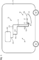
- the Figure 1 shows a rail vehicle 10, which is equipped with a fallwater operated bidet toilet facility 20.
- the fallwater operated bidet toilet installation 20 comprises a fallwater installation 30 and a bidet toilet unit 40 connected to it.
- the bidet toilet unit 40 has flushing nozzles 41 which are used for flushing the toilet when the bidet toilet unit 40 is used.
- the bidet toilet unit 40 is equipped with one or more bidet nozzles 42, which are arranged together with the flushing nozzles 41 in the toilet bowl 43 or are integrated therein. In the following, it is assumed as an example that a single bidet nozzle 42 is integrated in the toilet bowl 43.
- the flushing nozzles 41 are connected via a flushing water line 100 to a preferably unheated main water line 200 of the falling water system 30.
- the main water line 200 connects the rinse water line 100 to a water tank 300 of the fall water system 30.
- a flushing water actuation valve 110 is provided in the flushing water line 100, with which the flushing of the toilet of the bidet-toilet unit 40 can be controlled. If the flushing water actuation valve 110 is triggered, a predetermined amount of water will get through the flushing water line 100 and the flushing nozzles 41 into the toilet bowl 43 and clean the toilet.
- the bidet nozzle 42 is connected to the unheated main water line 200 via a water line 400.
- the water pipe 400 is preferably provided with a pipe trace heater 410, which can heat up the water flowing through the water pipe 400 or the water therein.
- the water pipe 400 is accordingly referred to below as the hot water pipe 400, since it releases preheated or warmed water downstream through the pipe trace heater 410.
- a bidet actuation valve 420 is arranged in the hot water line 400 and can be a solenoid valve, for example.
- the bidet actuation valve 420 preferably allows a fixed, predetermined amount of water to flow downstream in the direction of the bidet nozzle 42 in order to enable the bidet function of the bidet toilet unit 40 when actuated.
- the amount of water that is let through per actuation of the bidet actuation valve 420 is preferably selected such that it is sufficiently large for a normal bidet use.
- the amount of water released per actuation is preferably in a range between 0.2 l and 0.5 l in a time period between 10 and 30 seconds.
- the heating power of the pipe heating 410 and the diameter and length of the hot water pipe 400 are dimensioned such that the the amount of heated water or water column available in the hot water line 400 is sufficiently large for at least two bidet actuation processes.
- the rinsing water line 100 and the hot water line 400 are connected to the water tank 300 via the unheated main water line 200; alternatively, it can be provided that either the rinsing water line 100 and / or the hot water line 400 are connected directly to the water tank 300.
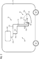
- the Figure 2 shows the rail vehicle 10 according to FIG Figure 1 or the bidet toilet system 20 during the operation of the bidet function of the bidet toilet unit 40.
- the gravity causes the pipe heater 410 located upstream above the bidet control valve 420 and through the pipe trace heater 410
- the bidet nozzle 42 is a pivotable or adjustable spherical nozzle.
- a major advantage of the related Figures 1 and 2nd described fallwater powered bidet toilet facility 20 is that the water jet 500, which is emitted from the bidet nozzle 42 upwards beyond the upper edge 43a of the toilet bowl 43, will remain reliably inside the toilet bowl 43 and will re-enter the toilet bowl 43 within the inner edge of the toilet bowl 43. This is ensured due to the fall water operation or the gravity-related drainage of the water from the water tank 300, because the height of the water column in the water tank 300 and between the water tank 300 and the bidet nozzle 42 and the line cross section determine the water flow and the pressure conditions and thus determine the height and the width of the water jet 500 after exiting the bidet nozzle 42.
- the Figure 3 shows a further embodiment for a rail vehicle 10, which is equipped with a fallwater operated bidet toilet system 20.
- the bidet toilet system 20 according to Figure 3 equipped with an additional sink 600, which is provided with a tap 610.
- the water tap 610 is connected to the hot water line 400 via a hand wash valve 620, with which the bidet nozzle 42 of the bidet toilet unit 40 is also supplied with hot water.
- connection of the water tap 610 or the hand wash valve 620 to the hot water line 400 ensures that the wash basin 600 is operated with pleasantly tempered water.
- the pipe trace heater 410 is equipped with a thermostat and / or a temperature monitoring device which ensures that the water column located in the hot water line 400 has a predetermined limit temperature of, for example, 20 ° C.
- the Figure 4 shows an embodiment of a bidet toilet unit 40, which in the fallwater operated bidet toilet system 20 according to the Figures 1 to 3 can be used.
- the Figure 4 shows the bidet toilet unit 40 in a three-dimensional representation obliquely from the side.
- Three flushing nozzles 41 can be seen, which are preferably mounted in a rotationally symmetrical manner inside the toilet bowl 43 or are integrated into the inner surface 43b of the toilet bowl 43.
- a bidet nozzle 42 is integrated, with which an arcuate water jet, such as the water jet 500 according to FIG Figure 2 , solely due to gravity by the fall water system 30 according to the Figures 1 and 3rd can be generated.
- the bidet nozzle 42 is a spherical nozzle which can be adjusted during installation and / or maintenance in such a way that the curved water jet 500 according to FIG Figure 2 remains within the bowl area or within the inner contour of the bowl area of the toilet bowl 43.
- the bidet nozzle 42 of the in the Figure 4 underlying flushing nozzle 41 separated;
- the bidet nozzle 42 forms an combination nozzle with an associated rinsing nozzle 41, which can be assembled and adjusted in a single assembly step and has both a connection to the rinsing water line 100 and the hot water line 400 according to FIGS Figures 1 to 3 allowed.
Landscapes
- Health & Medical Sciences (AREA)
- Public Health (AREA)
- Epidemiology (AREA)
- Engineering & Computer Science (AREA)
- General Health & Medical Sciences (AREA)
- Mechanical Engineering (AREA)
- Molecular Biology (AREA)
- Life Sciences & Earth Sciences (AREA)
- Hydrology & Water Resources (AREA)
- Water Supply & Treatment (AREA)
- Bidet-Like Cleaning Device And Other Flush Toilet Accessories (AREA)
- Non-Flushing Toilets (AREA)
Description
- Bekanntermaßen können Fahrzeuge, wie Schienenfahrzeuge oder Busse, mit Toiletten ausgestattet werden.
- Darüber hinaus ist bekannt, mit Blick auf einen größeren Komfort und größere Hygiene neben Toiletten auch Bidets vorzusehen.
- Offenlegungsschrift
US 2010/0235978 A1 lehrt nun ein kombiniertes System aus Toilette und Bidet mit einer an der Toilette angeordneten, ausfahrbaren Sprühdüse. Dieses Bidet- und Toilettensystem ist zur Anwendung in Transportmitteln wie Flugzeuge, Schienen-, Wasser- oder Landfahrzeuge geeignet. - Die Druckschrift
GB 377 192 A - Der Erfindung liegt die Aufgabe zugrunde, ein Fahrzeug, insbesondere Schienenfahrzeug, anzugeben, das mit einer besonders komfortablen Sanitäreinrichtung ausgestattet ist.
- Diese Aufgabe wird erfindungsgemäß durch ein Fahrzeug mit den Merkmalen gemäß Patentanspruch 1 gelöst. Vorteilhafte Ausgestaltungen des erfindungsgemäßen Fahrzeugs sind in Unteransprüchen angegeben.
- Danach ist erfindungsgemäß vorgesehen, dass das Fahrzeug zumindest ein Bidet aufweist, das mit einer Fallwasseranlage in Verbindung steht und von dieser schwerkraftbedingt mit Wasser versorgt wird.
- Ein wesentlicher Vorteil des erfindungsgemäßen Fahrzeugs ist darin zu sehen, dass dieses durch das vorgesehene Bidet auch besonders hohen Anforderungen an Komfort und Hygiene entspricht.
- Ein weiterer wesentlicher Vorteil des erfindungsgemäßen Fahrzeugs besteht darin, dass der Betrieb des Bidets mit einer Fallwasseranlage erfolgt, also einer Wasseranlage, bei der die Wasserversorgung des Bidets schwerkraftbedingt durchgeführt wird. Der Vorteil einer fallwassergesteuerten bzw. schwerkraftbedingten Wasserversorgung ist darin zu sehen, dass der für die Bereitstellung der Bidetfunktion erforderliche Wasserstrahl stets einen vorgegebenen Druck und damit vorgegebene Strahleigenschaften, beispielsweise eine vorjustierte Bogenform und Bogenweite, aufweisen wird, die völlig bedienungsunabhängig ist und allein durch die technische Ausgestaltung der Fallwasseranlage, insbesondere die Höhe der über dem Bidet befindlichen Wassersäule, und die Einstellung der Auslassdüse(n) des Bidets bestimmt werden. Sind mit anderen Worten die Fallwasseranlage und das angeschlossene Bidet geeignet aufeinander abgestimmt, so lässt sich beispielsweise ohne Zutun oder Mitwirkung des Bidetnutzers gewährleisten, dass der während des Betriebs des Bidets bereitgestellte Wasserstrahl stets innerhalb der Bidetschüssel verbleibt. Im Unterschied zu handelsüblichen Bidets, bei denen ein Einstellen des Wasserstrahls durch manuelle Bedienung eines verstellbaren Ventils erfolgt, sind die Druckverhältnisse und damit die Ausgestaltung des Wasserstrahls bei dem erfindungsgemäßen Fahrzeug technisch fest vorgegeben und nutzerunabhängig.
- Die Fallwasseranlage weist einen räumlich oberhalb des Bidets angeordneten Wassertank auf, der mit dem Bidet über eine Wasserleitung verbunden ist, und die Wasserleitung zwischen Bidet und Wassertank ist zumindest abschnittsweise mittels einer Rohrbegleitheizung beheizbar oder beheizt und bildet eine Warmwasserleitung. Eine Vorwärmung des Wassers erhöht den Benutzungskomfort des Bidets signifikant.
- Für eine einfache Bedienung der Bidetfunktion ist die Warmwasserleitung mit einem Bidetbetätigungsventil ausgestattet, das pro Betätigung eine vorgegebene Wassermenge freigibt. Das Bidetbetätigungsventil ist bevorzugt ein Magnetventil.
- Dabei sind die Länge und der Querschnitt der Warmwasserleitung, die vom Bidetbetätigungsventil pro Betätigung freigegebene Wassermenge und die Heizleistung der Rohrbegleitheizung derart bemessen, dass eine zumindest zweimalige Auslösung der Bidetfunktion mit erwärmtem Wasser möglich ist.
- Das Bidet und eine Toilette bilden fürderhin eine integrierte Bidet-Toiletten-Einheit, bei der mindestens eine Bidetdüse, die die Bidetfunktion gewährleistet und mit der die Bidet-Toiletten-Einheit als Bidet betreibbar ist, und mindestens eine Spüldüse, die die Spülfunktion gewährleistet und mit der die Bidet-Toiletten-Einheit als Toilette betreibbar ist, in derselben Toilettenschüssel integriert sind. Dies wird insbesondere mit Blick auf einen minimalen Platzbedarf als vorteilhaft angesehen.
- Handelt es sich bei der Toilette um eine Vakuumtoilette, so wird es als vorteilhaft angesehen, wenn in der Toilettenschüssel ein Wasserstandsensor angebracht ist und mit dem Wasserstandsensor eine Steuereinrichtung in Verbindung steht, die bei Erreichen eines maximalen Wasserstandes in der Toilettenschüssel ein Absaugen der Toilettenschüssel auslöst.
- Mit Blick auf einen minimalen Energieverbrauch wird es als vorteilhaft angesehen, wenn die Spüldüse oder Spüldüsen mit dem Wassertank der Fallwasseranlage über eine Spülwasserleitung in Verbindung stehen, die von der das Bidet mit Wasser versorgenden Warmwasserleitung getrennt ist.
- Die Spülwasserleitung ist vorzugsweise unbeheizt.
- Um eine separate Bedienung der Toilettenfunktion und der Bidetfunktion zu ermöglichen, wird es als vorteilhaft angesehen, wenn die Spülwasserleitung mit einem Spülwasserbetätigungsventil ausgestattet ist, mit dem sich durch Ventilbetätigung die Spülfunktion der Toilette aktivieren lässt, und die Warmwasserleitung mit einem Bidetbetätigungsventil ausgestattet ist, mit dem sich durch Ventilbetätigung die Bidetfunktion aktivieren lässt, wobei sich das Bidetbetätigungsventil und das Spülwasserbetätigungsventil unabhängig voneinander betätigen lassen.
- Bezüglich der Ausgestaltung der Fallwasseranlage wird es als vorteilhaft angesehen, wenn die Spülwasserleitung stromabwärts mit der oder den Spüldüsen und stromaufwärts unmittelbar mit dem Wassertank oder über eine mit dem Wassertank in Verbindung stehende unbeheizte Hauptversorgungsleitung mittelbar mit dem Wassertank verbunden ist und die Warmwasserleitung stromabwärts mit der oder den Bidetdüsen und stromaufwärts unmittelbar mit dem Wassertank oder über eine mit dem Wassertank in Verbindung stehende unbeheizte Hauptversorgungsleitung mittelbar mit dem Wassertank verbunden ist.
- Vorzugsweise werden die Bidetdüse oder die Bidetdüsen jeweils durch eine verstellbare Kugeldüse gebildet. Kugeldüsen ermöglichen in besonders einfacher Weise eine optimale Einstellung des Bidetwasserstrahls.
- Alternativ oder zusätzlich kann vorgesehen sein, dass zumindest eine der Bidetdüsen und zumindest eine der Spüldüsen durch eine Kombidüse gebildet ist, bei der ein Ausgangsdüsenabschnitt der Kombidüse die Bidetdüse und ein Ausgangsdüsenabschnitt die Spüldüse bildet.
- An die Warmwasserleitung der Fallwasseranlage kann darüber hinaus ein Waschbecken angeschlossen sein, das demgemäß mit Warmwasser betrieben wird.
- Die Erfindung wird nachfolgend anhand von Ausführungsbeispielen näher erläutert; dabei zeigen beispielhaft:
- Figur 1
- ein Ausführungsbeispiel für ein erfindungsgemäßes Schienenfahrzeug, das mit einer fallwasserbetriebenen Bidet-Toilettenanlage ausgestattet ist,
- Figur 2
- das Schienenfahrzeug gemäß
Figur 1 während des Betriebs der Bidetfunktion der fallwasserbetriebenen Bidet-Toilettenanlage, - Figur 3
- ein Ausführungsbeispiel für ein erfindungsgemäßes Schienenfahrzeug, bei dem eine fallwasserbetriebene Bidet-Toilettenanlage zusätzlich mit einem Waschbecken und Wasserhahn ausgestattet ist, und
- Figur 4
- ein Ausführungsbeispiel für eine Bidet-Toiletteneinheit, wie sie bei den Schienenfahrzeugen gemäß den
Figuren 1 bis 3 eingesetzt werden kann. - In den Figuren werden der Übersicht halber für identische oder vergleichbare Komponenten stets dieselben Bezugszeichen verwendet.
- Die
Figur 1 zeigt ein Schienenfahrzeug 10, das mit einer fallwasserbetriebenen Bidet-Toilettenanlage 20 ausgestattet ist. Die fallwasserbetriebene Bidet-Toilettenanlage 20 umfasst eine Fallwasseranlage 30 sowie eine mit dieser in Verbindung stehende Bidet-Toiletteneinheit 40. - Die Bidet-Toiletteneinheit 40 weist Spüldüsen 41 auf, die zur Toilettenspülung im Falle einer Toilettenbenutzung der Bidet-Toiletteneinheit 40 dienen.
- Zusätzlich zu den Spüldüsen 41 ist die Bidet-Toiletteneinheit 40 mit einer oder mehreren Bidetdüsen 42 ausgestattet, die gemeinsam mit den Spüldüsen 41 in der Toilettenschüssel 43 angeordnet bzw. in diese integriert sind. Nachfolgend wird beispielhaft davon ausgegangen, dass in der Toilettenschüssel 43 eine einzige Bidetdüse 42 integriert ist.
- Die Spüldüsen 41 stehen über eine Spülwasserleitung 100 mit einer vorzugsweise unbeheizten Hauptwasserleitung 200 der Fallwasseranlage 30 in Verbindung. Die Hauptwasserleitung 200 verbindet die Spülwasserleitung 100 mit einem Wassertank 300 der Fallwasseranlage 30.
- In der Spülwasserleitung 100 ist ein Spülwasserbetätigungsventil 110 vorgesehen, mit dem sich die Toilettenspülung der Bidet-Toiletteneinheit 40 steuern lässt. Wird das Spülwasserbetätigungsventil 110 ausgelöst, so wird eine vorgegebene Wassermenge durch die Spülwasserleitung 100 und die Spüldüsen 41 in die Toilettenschüssel 43 gelangen und die Toilette reinigen.
- Die Bidetdüse 42 steht über eine Wasserleitung 400 mit der unbeheizten Hauptwasserleitung 200 in Verbindung. Die Wasserleitung 400 ist vorzugsweise mit einer Rohrbegleitheizung 410 versehen, die das durch die Wasserleitung 400 fließende Wasser bzw. das darin stehende Wasser aufheizen kann. Die Wasserleitung 400 wird demgemäß nachfolgend als Warmwasserleitung 400 bezeichnet, da sie stromabwärts durch die Rohrbegleitheizung 410 vorgewärmtes bzw. angewärmtes Wasser abgibt.
- In der Warmwasserleitung 400 ist ein Bidetbetätigungsventil 420 angeordnet, bei dem es sich beispielsweise um ein Magnetventil handeln kann. Das Bidetbetätigungsventil 420 lässt vorzugsweise pro Betätigung eine fest vorgegebene Wassermenge stromabwärts in Richtung Bidetdüse 42 fließen, um die Bidetfunktion der Bidet-Toiletteneinheit 40 bei Betätigung zu ermöglichen. Die Wassermenge, die pro Betätigung des Bidetbetätigungsventils 420 durchgelassen wird, ist vorzugsweise derart gewählt, dass diese für eine übliche Bidetnutzung ausreichend groß ist. Die pro Betätigung freigesetzte Wassermenge liegt vorzugsweise in einem Bereich zwischen 0,2 l und 0,5 l in einer Zeitspanne zwischen 10 und 30 Sekunden.
- Um zu gewährleisten, dass bei Bidetbenutzung auch im Falle einer mehrfachen Betätigung des Bidetbetätigungsventils 420 ausreichend warmes Wasser zur Verfügung steht, wird es als vorteilhaft angesehen, wenn die Heizleistung der Rohrbegleitheizung 410 sowie der Durchmesser und die Länge der Warmwasserleitung 400 derart bemessen sind, dass die in der Warmwasserleitung 400 zur Verfügung stehende erwärmte Wassermenge bzw. Wassersäule für zumindest zwei Bidetbetätigungsvorgänge ausreichend groß ist.
- Bei dem Ausführungsbeispiel gemäß
Figur 1 stehen die Spülwasserleitung 100 und die Warmwasserleitung 400 mit dem Wassertank 300 über die unbeheizte Hauptwasserleitung 200 in Verbindung; alternativ kann vorgesehen sein, dass entweder die Spülwasserleitung 100 und/oder die Warmwasserleitung 400 unmittelbar mit dem Wassertank 300 verbunden werden. - Die
Figur 2 zeigt das Schienenfahrzeug 10 gemäßFigur 1 bzw. die Bidet-Toilettenanlage 20 während des Betriebs der Bidetfunktion der Bidet-Toiletteneinheit 40. Sobald das Bidetbetätigungsventil 420 aktiviert wird und ein Wasserfluss durch das Bidetbetätigungsventil 420 erlaubt wird, wird aufgrund der Schwerkraft das stromaufwärts über dem Bidetbetätigungsventil 420 befindliche und durch die Rohrbegleitheizung 410 vorgewärmte Wasser in Richtung Bidetdüse 42 fließen und in Form eines bogenförmigen Wasserstrahls, der in derFigur 2 mit dem Bezugszeichen 500 gekennzeichnet ist, zumindest abschnittsweise lokal den oberen Rand 43a der Toilettenschüssel 43 passieren, bevor es in der Toilettenschüssel 43 landet. - Um die in der
Figur 2 dargestellte gekrümmte Bahn des Wasserstrahls 500 einstellen bzw. ggf. nachjustieren zu können, wird es als vorteilhaft angesehen, wenn es sich bei der Bidetdüse 42 um eine verschwenkbare oder verstellbare Kugeldüse handelt. - Ein wesentlicher Vorteil der im Zusammenhang mit den
Figuren 1 und2 beschriebenen fallwasserbetriebenen Bidet-Toilettenanlage 20 besteht darin, dass der Wasserstrahl 500, der von der Bidetdüse 42 über den oberen Rand 43a der Toilettenschüssel 43 hinaus nach oben abgegeben wird, zuverlässig innerhalb der Toilettenschüssel 43 verbleiben wird und innerhalb des Innenrands der Toilettenschüssel 43 wieder in die Toilettenschüssel 43 eintreten wird. Dies ist aufgrund des Fallwasserbetriebs bzw. des schwerkraftbedingten Abfließens des Wassers aus dem Wassertank 300 gewährleistet, denn die Höhe der Wassersäule im Wassertank 300 und zwischen dem Wassertank 300 und der Bidetdüse 42 sowie der Leitungsquerschnitt legen den Wasserfluss sowie die Druckverhältnisse fest und bestimmen damit die Höhe und die Weite des Wasserstrahls 500 nach dem Verlassen der Bidetdüse 42. - Die
Figur 3 zeigt ein weiteres Ausführungsbeispiel für ein Schienenfahrzeug 10, das mit einer fallwasserbetriebenen Bidet-Toilettenanlage 20 ausgestattet ist. Im Unterschied zu der Bidet-Toilettenanlage 20 gemäß denFiguren 1 und2 ist die Bidet-Toilettenanlage 20 gemäßFigur 3 mit einem zusätzlichen Waschbecken 600 ausgestattet, das mit einem Wasserhahn 610 versehen ist. Der Wasserhahn 610 steht über ein Handwaschventil 620 mit der Warmwasserleitung 400 in Verbindung, mit der auch die Bidetdüse 42 der Bidet-Toiletteneinheit 40 mit Warmwasser versorgt wird. - Aufgrund des Anschlusses des Wasserhahns 610 bzw. des Handwaschventils 620 an die Warmwasserleitung 400 wird gewährleistet, dass das Waschbecken 600 mit angenehm temperiertem Wasser betrieben wird.
- Um zu vermeiden, dass die Wassertemperatur innerhalb der Warmwasserleitung 400 zu sehr ansteigt, wird es als vorteilhaft angesehen, wenn die Rohrbegleitheizung 410 mit einem Thermostat und/oder einer Temperaturüberwachungseinrichtung ausgestattet ist, die sicherstellt, dass die in der Warmwasserleitung 400 befindliche Wassersäule eine vorgegebene Grenztemperatur von beispielsweise 20°C nicht überschreitet.
- Die
Figur 4 zeigt ein Ausführungsbeispiel für eine Bidet-Toiletteneinheit 40, die bei der fallwasserbetriebenen Bidet-Toilettenanlage 20 gemäß denFiguren 1 bis 3 eingesetzt werden kann. DieFigur 4 zeigt die Bidet-Toiletteneinheit 40 in einer dreidimensionalen Darstellung schräg von der Seite. Man erkennt drei Spüldüsen 41, die vorzugsweise drehsymmetrisch im Inneren der Toilettenschüssel 43 angebracht sind bzw. in die Innenfläche 43b der Toilettenschüssel 43 integriert sind. - Ebenfalls in die Toilettenschüssel 43, und zwar ebenfalls in die Innenfläche 43b der Toilettenschüssel 43, ist eine Bidetdüse 42 integriert, mit der sich ein bogenförmiger Wasserstrahl, wie beispielsweise der Wasserstrahl 500 gemäß
Figur 2 , allein schwerkraftbedingt durch die Fallwasseranlage 30 gemäß denFiguren 1 und3 erzeugen lässt. - Bei dem Ausführungsbeispiel gemäß
Figur 4 handelt es sich bei der Bidetdüse 42 um eine Kugeldüse, die im Rahmen der Installation und/oder Wartung derart justiert werden kann, dass der bogenförmige Wasserstrahl 500 gemäßFigur 2 innerhalb des Schüsselbereichs bzw. innerhalb der Innenkontur des Schüsselbereichs der Toilettenschüssel 43 verbleibt. - Bei dem Ausführungsbeispiel gemäß
Figur 4 ist die Bidetdüse 42 von der in derFigur 4 darunter liegenden Spüldüse 41 getrennt; mit Blick auf einen minimalen Montageaufwand kann alternativ vorgesehen werden, dass die Bidetdüse 42 mit einer zugeordneten Spüldüse 41 eine Kombidüse bildet, die in einem einzigen Montageschritt montiert und justiert werden kann und sowohl einen Anschluss an die Spülwasserleitung 100 als auch die Warmwasserleitung 400 gemäß denFiguren 1 bis 3 erlaubt.
Claims (9)
- Fahrzeug, insbesondere Schienenfahrzeug (10),wobei das Fahrzeug zumindest ein Bidet aufweist, wobei das Bidet und eine Toilette eine integrierte Bidet-Toiletteneinheit (40) bilden, bei der mindestens eine Bidetdüse (42), die die Bidetfunktion gewährleistet und mit der die Bidet-Toiletteneinheit 40) als Bidet betreibbar ist, und mindestens eine Spüldüse (41), die die Spülfunktion gewährleistet und mit der die Bidet-Toiletteneinheit (40) als Toilette betreibbar ist, in derselben Toilettenschüssel (43) integriert sind, wobei
das Bidet mit einer Fallwasseranlage (30) in Verbindung steht und von dieser schwerkraftbedingt mit Wasser versorgt wird, wobei- die Fallwasseranlage (30) einen räumlich oberhalb des Bidets angeordneten Wassertank (300) aufweist, der mit dem Bidet über eine Wasserleitung verbunden ist, und- die Wasserleitung zwischen Bidet und Wassertank (300) zumindest abschnittsweise mittels einer Rohrbegleitheizung (410) beheizbar oder beheizt ist und eine Warmwasserleitung (400) bildet, und wobei- die Warmwasserleitung (400) mit einem Bidetbetätigungsventil (420) ausgestattet ist, mit dem sich durch Ventilbetätigung die Bidetfunktion aktivieren lässt,- wobei das Bidetbetätigungsventil (420) pro Betätigung eine vorgegebene Wassermenge freigibt und- die Länge und der Querschnitt der Warmwasserleitung (400), die vom Bidetbetätigungsventil (420) pro Betätigung freigegebene Wassermenge und die Heizleistung der Rohrbegleitheizung (410) derart bemessen sind, dass eine zumindest zweimalige Auslösung der Bidetfunktion mit erwärmtem Wasser möglich ist. - Fahrzeug nach Anspruch 1,
dadurch gekennzeichnet, dass- die Toilette eine Vakuumtoilette ist,- in der Toilettenschüssel (43) ein Wasserstandsensor angebracht ist und- mit dem Wasserstandsensor eine Steuereinrichtung in Verbindung steht, die bei Erreichen eines maximalen Wasserstandes in der Toilettenschüssel (43) ein Absaugen der Toilettenschüssel (43) auslöst. - Fahrzeug nach Anspruch 1 oder 2,
dadurch gekennzeichnet, dass
die Spüldüse (41) oder Spüldüsen mit dem Wassertank (300) der Fallwasseranlage (30) über eine Spülwasserleitung (100) in Verbindung stehen, die von der das Bidet mit Wasser versorgenden Warmwasserleitung (400) getrennt ist. - Fahrzeug nach Anspruch 3,
dadurch gekennzeichnet, dass
die Spülwasserleitung (100) unbeheizt ist. - Fahrzeug nach Anspruch 3 oder 4,
dadurch gekennzeichnet, dass- die Spülwasserleitung (100) mit einem Spülwasserbetätigungsventil (110) ausgestattet ist, mit dem sich durch Ventilbetätigung die Spülfunktion der Toilette aktivieren lässt, und- die Warmwasserleitung (400) mit einem Bidetbetätigungsventil (420) ausgestattet ist, mit dem sich durch Ventilbetätigung die Bidetfunktion aktivieren lässt,- wobei sich das Bidetbetätigungsventil (420) und das Spülwasserbetätigungsventil (110) unabhängig voneinander betätigen lassen. - Fahrzeug nach einem der voranstehenden Ansprüche,
dadurch gekennzeichnet, dass- die Spülwasserleitung (100) stromabwärts mit der oder den Spüldüsen und stromaufwärts unmittelbar mit dem Wassertank (300) oder über eine mit dem Wassertank (300) in Verbindung stehende unbeheizte Hauptversorgungsleitung (200) mittelbar mit dem Wassertank (300) verbunden ist und- die Warmwasserleitung (400) stromabwärts mit der oder den Bidetdüsen (42) und stromaufwärts unmittelbar mit dem Wassertank (300) oder über eine mit dem Wassertank (300) in Verbindung stehende unbeheizte Hauptversorgungsleitung (200) mittelbar mit dem Wassertank (300) verbunden ist. - Fahrzeug nach einem der voranstehenden Ansprüche,
dadurch gekennzeichnet, dass
die Bidetdüse (42) oder die Bidetdüsen (42) jeweils durch eine verstellbare Kugeldüse gebildet sind. - Fahrzeug nach einem der voranstehenden Ansprüche,
dadurch gekennzeichnet, dass
zumindest eine der Bidetdüsen (42) und zumindest eine der Spüldüsen durch eine Kombidüse gebildet ist, bei der ein Ausgangsdüsenabschnitt der Kombidüse die Bidetdüse (42) und ein Ausgangsdüsenabschnitt die Spüldüse (41) bildet. - Fahrzeug nach einem der voranstehenden Ansprüche,
dadurch gekennzeichnet, dass
an die Warmwasserleitung (400) parallel ein Waschbecken (600) angeschlossen ist.
Applications Claiming Priority (2)
| Application Number | Priority Date | Filing Date | Title |
|---|---|---|---|
| DE102014212330.5A DE102014212330A1 (de) | 2014-06-26 | 2014-06-26 | Fahrzeug mit Bidet |
| PCT/EP2015/062706 WO2015197348A1 (de) | 2014-06-26 | 2015-06-08 | Fahrzeug mit bidet |
Publications (2)
| Publication Number | Publication Date |
|---|---|
| EP3137692A1 EP3137692A1 (de) | 2017-03-08 |
| EP3137692B1 true EP3137692B1 (de) | 2020-06-03 |
Family
ID=53398072
Family Applications (1)
| Application Number | Title | Priority Date | Filing Date |
|---|---|---|---|
| EP15729127.9A Active EP3137692B1 (de) | 2014-06-26 | 2015-06-08 | Fahrzeug mit bidet |
Country Status (5)
| Country | Link |
|---|---|
| EP (1) | EP3137692B1 (de) |
| CN (1) | CN206486960U (de) |
| DE (1) | DE102014212330A1 (de) |
| ES (1) | ES2813680T3 (de) |
| WO (1) | WO2015197348A1 (de) |
Cited By (1)
| Publication number | Priority date | Publication date | Assignee | Title |
|---|---|---|---|---|
| WO2024227567A1 (de) * | 2023-05-03 | 2024-11-07 | Siemens Mobility GmbH | Reinigungsroutine für eine bidet-düse einer integrierten toiletten-bidet-einheit und sanitärzelle für ein fahrzeug des öffentlichen personenverkehrs |
Families Citing this family (2)
| Publication number | Priority date | Publication date | Assignee | Title |
|---|---|---|---|---|
| DE102019205620A1 (de) * | 2019-04-17 | 2020-10-22 | Siemens Mobility GmbH | Thermische Entkeimung von Frischwasseranlagen in Schienenfahrzeugen |
| DE102023204085A1 (de) | 2023-05-03 | 2024-11-07 | Siemens Mobility GmbH | Sanitäreinrichtung für ein Schienenfahrzeug mit rückverkeimungsfreiem Bidet |
Family Cites Families (9)
| Publication number | Priority date | Publication date | Assignee | Title |
|---|---|---|---|---|
| GB377192A (en) * | 1931-04-15 | 1932-07-15 | Stone J & Co Ltd | Improvements in and connected with the water services or supplies on travelling vehicles such as railway carriages |
| DE2530913C3 (de) * | 1975-07-10 | 1979-06-13 | Rainer 8990 Lindau Lutz | ToUettensitz mit Waschvorrichtung |
| US4422190A (en) * | 1982-06-01 | 1983-12-27 | Huang Chuan Chih | Safety toilet seat |
| DE8300009U1 (de) * | 1983-01-03 | 1983-06-01 | Steinrücke, Elmar, 4600 Dortmund | Toilettendeckel-bidet |
| DE19852044A1 (de) * | 1998-11-11 | 2000-05-18 | Knaus Gmbh Jandelsbrunn | Verfahren zum Beheizen eines Wasserversungssystems eines Straßenfahrzeugs und Straßenfahrzeug mit Wasserversorgungssystem |
| DE50304146D1 (de) * | 2002-05-30 | 2006-08-17 | Geberit Technik Ag | Spülvorrichtung einer toilettenanlage mit spülarm zum ausspülen einer toilettenschüssel |
| CA2645126A1 (en) * | 2008-11-19 | 2010-05-19 | Juan Bautista Truqui | Washroom bus |
| DE102009013558B4 (de) * | 2009-03-17 | 2016-02-18 | Airbus Operations Gmbh | Kombinierter Bidet-Toiletten-Aufbau für Flugzeuge |
| DE102012201146B3 (de) * | 2012-01-26 | 2013-05-16 | Siemens Aktiengesellschaft | Wasserauslass für eine Sanitäranlage eines Schienenfahrzeugs |
-
2014
- 2014-06-26 DE DE102014212330.5A patent/DE102014212330A1/de not_active Withdrawn
-
2015
- 2015-06-08 ES ES15729127T patent/ES2813680T3/es active Active
- 2015-06-08 CN CN201590000760.0U patent/CN206486960U/zh not_active Expired - Lifetime
- 2015-06-08 EP EP15729127.9A patent/EP3137692B1/de active Active
- 2015-06-08 WO PCT/EP2015/062706 patent/WO2015197348A1/de not_active Ceased
Non-Patent Citations (1)
| Title |
|---|
| None * |
Cited By (1)
| Publication number | Priority date | Publication date | Assignee | Title |
|---|---|---|---|---|
| WO2024227567A1 (de) * | 2023-05-03 | 2024-11-07 | Siemens Mobility GmbH | Reinigungsroutine für eine bidet-düse einer integrierten toiletten-bidet-einheit und sanitärzelle für ein fahrzeug des öffentlichen personenverkehrs |
Also Published As
| Publication number | Publication date |
|---|---|
| ES2813680T3 (es) | 2021-03-24 |
| EP3137692A1 (de) | 2017-03-08 |
| WO2015197348A1 (de) | 2015-12-30 |
| DE102014212330A1 (de) | 2015-12-31 |
| CN206486960U (zh) | 2017-09-12 |
Similar Documents
| Publication | Publication Date | Title |
|---|---|---|
| EP3144435B1 (de) | Verfahren zum betrieb einer sanitärarmatur und sanitärarmatur | |
| EP3951110B1 (de) | Spültoilette | |
| EP2938790B1 (de) | Wc-aufsatz mit duscheinrichtung | |
| EP3580394B1 (de) | Spülvorrichtung für eine sanitäreinrichtung sowie toiletten- oder urinalspülung | |
| WO2003102315A1 (de) | Spülvorrichtung einer toilettenanlage mit spülarm zum ausspülen einer toilettenschüssel | |
| EP3170940B1 (de) | Dusch-wc mit einem wassererhitzer | |
| EP2402519A1 (de) | Spülvorrichtung zum Spülen einer Klosettschüssel, Wasserklosett mit einer solchen Spülvorrichtung und Klosettschüssel | |
| DE102014212330A1 (de) | Fahrzeug mit Bidet | |
| DE102015106221A1 (de) | Sanitäreinrichtung | |
| EP3141668B1 (de) | Dusch-wc mit durchlauferhitzer und boiler | |
| EP2095880A1 (de) | Wascheinrichtung | |
| DE102023204085A1 (de) | Sanitäreinrichtung für ein Schienenfahrzeug mit rückverkeimungsfreiem Bidet | |
| DE102012112752A1 (de) | WC mit einem WC-Körper sowie einer Duscheinrichtung | |
| WO2022049033A1 (de) | Bidetsystem | |
| EP3935226A1 (de) | Dusch-einrichtung und dusch wc mit solch einer dusch-einrichtung | |
| DE202011101271U1 (de) | Duscheinrichtung für WCs oder Bidets | |
| DE102015101651B4 (de) | Sanitärarmatur | |
| DE202012100840U1 (de) | Einrichtung zur Erweiterung von Toiletten zu einem WC-Bidet | |
| DE102007010793B4 (de) | Duschanordnung | |
| EP2527546A1 (de) | Duscheinrichtung für WCs oder Bidets | |
| DE102023204083A1 (de) | Reinigungsroutine für eine Bidet-Düse einer integrierten Toiletten-Bidet-Einheit | |
| AT224027B (de) | Bidet mit Regelung des Wasserdruckes | |
| DE19629518B4 (de) | Zusätzliche Unterdusche für Klosetts | |
| DE202023105229U1 (de) | Brunnen zur Trinkwasserentnahme | |
| DE202015006214U1 (de) | Dusch-WC mit Durchlauferhitzer und Boiler |
Legal Events
| Date | Code | Title | Description |
|---|---|---|---|
| STAA | Information on the status of an ep patent application or granted ep patent |
Free format text: STATUS: THE INTERNATIONAL PUBLICATION HAS BEEN MADE |
|
| PUAI | Public reference made under article 153(3) epc to a published international application that has entered the european phase |
Free format text: ORIGINAL CODE: 0009012 |
|
| STAA | Information on the status of an ep patent application or granted ep patent |
Free format text: STATUS: REQUEST FOR EXAMINATION WAS MADE |
|
| 17P | Request for examination filed |
Effective date: 20161115 |
|
| AK | Designated contracting states |
Kind code of ref document: A1 Designated state(s): AL AT BE BG CH CY CZ DE DK EE ES FI FR GB GR HR HU IE IS IT LI LT LU LV MC MK MT NL NO PL PT RO RS SE SI SK SM TR |
|
| AX | Request for extension of the european patent |
Extension state: BA ME |
|
| RAP1 | Party data changed (applicant data changed or rights of an application transferred) |
Owner name: SIEMENS AKTIENGESELLSCHAFT |
|
| DAV | Request for validation of the european patent (deleted) | ||
| DAX | Request for extension of the european patent (deleted) | ||
| RAP1 | Party data changed (applicant data changed or rights of an application transferred) |
Owner name: SIEMENS MOBILITY GMBH |
|
| STAA | Information on the status of an ep patent application or granted ep patent |
Free format text: STATUS: EXAMINATION IS IN PROGRESS |
|
| 17Q | First examination report despatched |
Effective date: 20190606 |
|
| GRAP | Despatch of communication of intention to grant a patent |
Free format text: ORIGINAL CODE: EPIDOSNIGR1 |
|
| STAA | Information on the status of an ep patent application or granted ep patent |
Free format text: STATUS: GRANT OF PATENT IS INTENDED |
|
| GRAJ | Information related to disapproval of communication of intention to grant by the applicant or resumption of examination proceedings by the epo deleted |
Free format text: ORIGINAL CODE: EPIDOSDIGR1 |
|
| STAA | Information on the status of an ep patent application or granted ep patent |
Free format text: STATUS: EXAMINATION IS IN PROGRESS |
|
| GRAP | Despatch of communication of intention to grant a patent |
Free format text: ORIGINAL CODE: EPIDOSNIGR1 |
|
| STAA | Information on the status of an ep patent application or granted ep patent |
Free format text: STATUS: GRANT OF PATENT IS INTENDED |
|
| INTG | Intention to grant announced |
Effective date: 20200110 |
|
| INTC | Intention to grant announced (deleted) | ||
| INTG | Intention to grant announced |
Effective date: 20200129 |
|
| GRAS | Grant fee paid |
Free format text: ORIGINAL CODE: EPIDOSNIGR3 |
|
| GRAA | (expected) grant |
Free format text: ORIGINAL CODE: 0009210 |
|
| STAA | Information on the status of an ep patent application or granted ep patent |
Free format text: STATUS: THE PATENT HAS BEEN GRANTED |
|
| AK | Designated contracting states |
Kind code of ref document: B1 Designated state(s): AL AT BE BG CH CY CZ DE DK EE ES FI FR GB GR HR HU IE IS IT LI LT LU LV MC MK MT NL NO PL PT RO RS SE SI SK SM TR |
|
| REG | Reference to a national code |
Ref country code: GB Ref legal event code: FG4D Free format text: NOT ENGLISH |
|
| REG | Reference to a national code |
Ref country code: CH Ref legal event code: EP Ref country code: AT Ref legal event code: REF Ref document number: 1277159 Country of ref document: AT Kind code of ref document: T Effective date: 20200615 |
|
| REG | Reference to a national code |
Ref country code: DE Ref legal event code: R096 Ref document number: 502015012713 Country of ref document: DE |
|
| REG | Reference to a national code |
Ref country code: LT Ref legal event code: MG4D |
|
| PG25 | Lapsed in a contracting state [announced via postgrant information from national office to epo] |
Ref country code: SE Free format text: LAPSE BECAUSE OF FAILURE TO SUBMIT A TRANSLATION OF THE DESCRIPTION OR TO PAY THE FEE WITHIN THE PRESCRIBED TIME-LIMIT Effective date: 20200603 Ref country code: FI Free format text: LAPSE BECAUSE OF FAILURE TO SUBMIT A TRANSLATION OF THE DESCRIPTION OR TO PAY THE FEE WITHIN THE PRESCRIBED TIME-LIMIT Effective date: 20200603 Ref country code: NO Free format text: LAPSE BECAUSE OF FAILURE TO SUBMIT A TRANSLATION OF THE DESCRIPTION OR TO PAY THE FEE WITHIN THE PRESCRIBED TIME-LIMIT Effective date: 20200903 Ref country code: GR Free format text: LAPSE BECAUSE OF FAILURE TO SUBMIT A TRANSLATION OF THE DESCRIPTION OR TO PAY THE FEE WITHIN THE PRESCRIBED TIME-LIMIT Effective date: 20200904 Ref country code: LT Free format text: LAPSE BECAUSE OF FAILURE TO SUBMIT A TRANSLATION OF THE DESCRIPTION OR TO PAY THE FEE WITHIN THE PRESCRIBED TIME-LIMIT Effective date: 20200603 |
|
| PGFP | Annual fee paid to national office [announced via postgrant information from national office to epo] |
Ref country code: ES Payment date: 20200909 Year of fee payment: 6 |
|
| REG | Reference to a national code |
Ref country code: NL Ref legal event code: MP Effective date: 20200603 |
|
| PG25 | Lapsed in a contracting state [announced via postgrant information from national office to epo] |
Ref country code: BG Free format text: LAPSE BECAUSE OF FAILURE TO SUBMIT A TRANSLATION OF THE DESCRIPTION OR TO PAY THE FEE WITHIN THE PRESCRIBED TIME-LIMIT Effective date: 20200903 Ref country code: LV Free format text: LAPSE BECAUSE OF FAILURE TO SUBMIT A TRANSLATION OF THE DESCRIPTION OR TO PAY THE FEE WITHIN THE PRESCRIBED TIME-LIMIT Effective date: 20200603 Ref country code: RS Free format text: LAPSE BECAUSE OF FAILURE TO SUBMIT A TRANSLATION OF THE DESCRIPTION OR TO PAY THE FEE WITHIN THE PRESCRIBED TIME-LIMIT Effective date: 20200603 Ref country code: HR Free format text: LAPSE BECAUSE OF FAILURE TO SUBMIT A TRANSLATION OF THE DESCRIPTION OR TO PAY THE FEE WITHIN THE PRESCRIBED TIME-LIMIT Effective date: 20200603 |
|
| PG25 | Lapsed in a contracting state [announced via postgrant information from national office to epo] |
Ref country code: NL Free format text: LAPSE BECAUSE OF FAILURE TO SUBMIT A TRANSLATION OF THE DESCRIPTION OR TO PAY THE FEE WITHIN THE PRESCRIBED TIME-LIMIT Effective date: 20200603 Ref country code: AL Free format text: LAPSE BECAUSE OF FAILURE TO SUBMIT A TRANSLATION OF THE DESCRIPTION OR TO PAY THE FEE WITHIN THE PRESCRIBED TIME-LIMIT Effective date: 20200603 |
|
| PG25 | Lapsed in a contracting state [announced via postgrant information from national office to epo] |
Ref country code: SM Free format text: LAPSE BECAUSE OF FAILURE TO SUBMIT A TRANSLATION OF THE DESCRIPTION OR TO PAY THE FEE WITHIN THE PRESCRIBED TIME-LIMIT Effective date: 20200603 Ref country code: EE Free format text: LAPSE BECAUSE OF FAILURE TO SUBMIT A TRANSLATION OF THE DESCRIPTION OR TO PAY THE FEE WITHIN THE PRESCRIBED TIME-LIMIT Effective date: 20200603 Ref country code: PT Free format text: LAPSE BECAUSE OF FAILURE TO SUBMIT A TRANSLATION OF THE DESCRIPTION OR TO PAY THE FEE WITHIN THE PRESCRIBED TIME-LIMIT Effective date: 20201006 Ref country code: CZ Free format text: LAPSE BECAUSE OF FAILURE TO SUBMIT A TRANSLATION OF THE DESCRIPTION OR TO PAY THE FEE WITHIN THE PRESCRIBED TIME-LIMIT Effective date: 20200603 Ref country code: RO Free format text: LAPSE BECAUSE OF FAILURE TO SUBMIT A TRANSLATION OF THE DESCRIPTION OR TO PAY THE FEE WITHIN THE PRESCRIBED TIME-LIMIT Effective date: 20200603 |
|
| REG | Reference to a national code |
Ref country code: CH Ref legal event code: PL |
|
| PG25 | Lapsed in a contracting state [announced via postgrant information from national office to epo] |
Ref country code: SK Free format text: LAPSE BECAUSE OF FAILURE TO SUBMIT A TRANSLATION OF THE DESCRIPTION OR TO PAY THE FEE WITHIN THE PRESCRIBED TIME-LIMIT Effective date: 20200603 Ref country code: PL Free format text: LAPSE BECAUSE OF FAILURE TO SUBMIT A TRANSLATION OF THE DESCRIPTION OR TO PAY THE FEE WITHIN THE PRESCRIBED TIME-LIMIT Effective date: 20200603 Ref country code: IS Free format text: LAPSE BECAUSE OF FAILURE TO SUBMIT A TRANSLATION OF THE DESCRIPTION OR TO PAY THE FEE WITHIN THE PRESCRIBED TIME-LIMIT Effective date: 20201003 |
|
| REG | Reference to a national code |
Ref country code: DE Ref legal event code: R097 Ref document number: 502015012713 Country of ref document: DE |
|
| REG | Reference to a national code |
Ref country code: ES Ref legal event code: FG2A Ref document number: 2813680 Country of ref document: ES Kind code of ref document: T3 Effective date: 20210324 |
|
| PG25 | Lapsed in a contracting state [announced via postgrant information from national office to epo] |
Ref country code: LU Free format text: LAPSE BECAUSE OF NON-PAYMENT OF DUE FEES Effective date: 20200608 Ref country code: MC Free format text: LAPSE BECAUSE OF FAILURE TO SUBMIT A TRANSLATION OF THE DESCRIPTION OR TO PAY THE FEE WITHIN THE PRESCRIBED TIME-LIMIT Effective date: 20200603 |
|
| PLBE | No opposition filed within time limit |
Free format text: ORIGINAL CODE: 0009261 |
|
| STAA | Information on the status of an ep patent application or granted ep patent |
Free format text: STATUS: NO OPPOSITION FILED WITHIN TIME LIMIT |
|
| PG25 | Lapsed in a contracting state [announced via postgrant information from national office to epo] |
Ref country code: LI Free format text: LAPSE BECAUSE OF NON-PAYMENT OF DUE FEES Effective date: 20200630 Ref country code: CH Free format text: LAPSE BECAUSE OF NON-PAYMENT OF DUE FEES Effective date: 20200630 Ref country code: DK Free format text: LAPSE BECAUSE OF FAILURE TO SUBMIT A TRANSLATION OF THE DESCRIPTION OR TO PAY THE FEE WITHIN THE PRESCRIBED TIME-LIMIT Effective date: 20200603 Ref country code: IE Free format text: LAPSE BECAUSE OF NON-PAYMENT OF DUE FEES Effective date: 20200608 |
|
| 26N | No opposition filed |
Effective date: 20210304 |
|
| PG25 | Lapsed in a contracting state [announced via postgrant information from national office to epo] |
Ref country code: SI Free format text: LAPSE BECAUSE OF FAILURE TO SUBMIT A TRANSLATION OF THE DESCRIPTION OR TO PAY THE FEE WITHIN THE PRESCRIBED TIME-LIMIT Effective date: 20200603 |
|
| PGFP | Annual fee paid to national office [announced via postgrant information from national office to epo] |
Ref country code: IT Payment date: 20210625 Year of fee payment: 7 |
|
| PGFP | Annual fee paid to national office [announced via postgrant information from national office to epo] |
Ref country code: BE Payment date: 20210618 Year of fee payment: 7 Ref country code: AT Payment date: 20210510 Year of fee payment: 7 |
|
| PG25 | Lapsed in a contracting state [announced via postgrant information from national office to epo] |
Ref country code: MT Free format text: LAPSE BECAUSE OF FAILURE TO SUBMIT A TRANSLATION OF THE DESCRIPTION OR TO PAY THE FEE WITHIN THE PRESCRIBED TIME-LIMIT Effective date: 20200603 Ref country code: CY Free format text: LAPSE BECAUSE OF FAILURE TO SUBMIT A TRANSLATION OF THE DESCRIPTION OR TO PAY THE FEE WITHIN THE PRESCRIBED TIME-LIMIT Effective date: 20200603 |
|
| PG25 | Lapsed in a contracting state [announced via postgrant information from national office to epo] |
Ref country code: MK Free format text: LAPSE BECAUSE OF FAILURE TO SUBMIT A TRANSLATION OF THE DESCRIPTION OR TO PAY THE FEE WITHIN THE PRESCRIBED TIME-LIMIT Effective date: 20200603 |
|
| REG | Reference to a national code |
Ref country code: ES Ref legal event code: FD2A Effective date: 20220805 |
|
| PG25 | Lapsed in a contracting state [announced via postgrant information from national office to epo] |
Ref country code: ES Free format text: LAPSE BECAUSE OF NON-PAYMENT OF DUE FEES Effective date: 20210609 |
|
| REG | Reference to a national code |
Ref country code: AT Ref legal event code: MM01 Ref document number: 1277159 Country of ref document: AT Kind code of ref document: T Effective date: 20220608 |
|
| REG | Reference to a national code |
Ref country code: BE Ref legal event code: MM Effective date: 20220630 |
|
| PG25 | Lapsed in a contracting state [announced via postgrant information from national office to epo] |
Ref country code: AT Free format text: LAPSE BECAUSE OF NON-PAYMENT OF DUE FEES Effective date: 20220608 |
|
| PG25 | Lapsed in a contracting state [announced via postgrant information from national office to epo] |
Ref country code: BE Free format text: LAPSE BECAUSE OF NON-PAYMENT OF DUE FEES Effective date: 20220630 |
|
| PG25 | Lapsed in a contracting state [announced via postgrant information from national office to epo] |
Ref country code: IT Free format text: LAPSE BECAUSE OF NON-PAYMENT OF DUE FEES Effective date: 20220608 |
|
| PGFP | Annual fee paid to national office [announced via postgrant information from national office to epo] |
Ref country code: DE Payment date: 20240819 Year of fee payment: 10 |
|
| PGFP | Annual fee paid to national office [announced via postgrant information from national office to epo] |
Ref country code: GB Payment date: 20240704 Year of fee payment: 10 |
|
| PGFP | Annual fee paid to national office [announced via postgrant information from national office to epo] |
Ref country code: FR Payment date: 20250613 Year of fee payment: 11 |
|
| PGFP | Annual fee paid to national office [announced via postgrant information from national office to epo] |
Ref country code: TR Payment date: 20250602 Year of fee payment: 11 |
|
| REG | Reference to a national code |
Ref country code: DE Ref legal event code: R119 Ref document number: 502015012713 Country of ref document: DE |
|
| GBPC | Gb: european patent ceased through non-payment of renewal fee |
Effective date: 20250608 |
|
| PG25 | Lapsed in a contracting state [announced via postgrant information from national office to epo] |
Ref country code: GB Free format text: LAPSE BECAUSE OF NON-PAYMENT OF DUE FEES Effective date: 20250608 |
|
| PG25 | Lapsed in a contracting state [announced via postgrant information from national office to epo] |
Ref country code: DE Free format text: LAPSE BECAUSE OF NON-PAYMENT OF DUE FEES Effective date: 20260101 |