EP3136695A1 - Modulare vorrichtung zum andocken mit kameravorsprungausrichtung - Google Patents
Modulare vorrichtung zum andocken mit kameravorsprungausrichtung Download PDFInfo
- Publication number
- EP3136695A1 EP3136695A1 EP16185008.6A EP16185008A EP3136695A1 EP 3136695 A1 EP3136695 A1 EP 3136695A1 EP 16185008 A EP16185008 A EP 16185008A EP 3136695 A1 EP3136695 A1 EP 3136695A1
- Authority
- EP
- European Patent Office
- Prior art keywords
- camera
- add
- contact array
- accordance
- modular
- Prior art date
- Legal status (The legal status is an assumption and is not a legal conclusion. Google has not performed a legal analysis and makes no representation as to the accuracy of the status listed.)
- Withdrawn
Links
- 238000003032 molecular docking Methods 0.000 title 1
- 238000004891 communication Methods 0.000 claims description 23
- 239000002537 cosmetic Substances 0.000 claims description 14
- 229910000831 Steel Inorganic materials 0.000 claims description 11
- 230000013011 mating Effects 0.000 claims description 11
- 239000010959 steel Substances 0.000 claims description 11
- CWYNVVGOOAEACU-UHFFFAOYSA-N Fe2+ Chemical compound [Fe+2] CWYNVVGOOAEACU-UHFFFAOYSA-N 0.000 claims description 5
- 230000000153 supplemental effect Effects 0.000 abstract description 3
- 238000000034 method Methods 0.000 description 9
- 230000006870 function Effects 0.000 description 8
- 238000003491 array Methods 0.000 description 5
- 230000008901 benefit Effects 0.000 description 2
- 230000001413 cellular effect Effects 0.000 description 2
- 230000008569 process Effects 0.000 description 2
- 238000003860 storage Methods 0.000 description 2
- 229910052779 Neodymium Inorganic materials 0.000 description 1
- 230000009471 action Effects 0.000 description 1
- 239000000919 ceramic Substances 0.000 description 1
- 238000005034 decoration Methods 0.000 description 1
- 238000010586 diagram Methods 0.000 description 1
- 230000000694 effects Effects 0.000 description 1
- 238000005516 engineering process Methods 0.000 description 1
- 239000000446 fuel Substances 0.000 description 1
- 230000000977 initiatory effect Effects 0.000 description 1
- 230000003993 interaction Effects 0.000 description 1
- 238000005304 joining Methods 0.000 description 1
- 238000004519 manufacturing process Methods 0.000 description 1
- 238000010295 mobile communication Methods 0.000 description 1
- QEFYFXOXNSNQGX-UHFFFAOYSA-N neodymium atom Chemical compound [Nd] QEFYFXOXNSNQGX-UHFFFAOYSA-N 0.000 description 1
- 230000006855 networking Effects 0.000 description 1
- 230000000717 retained effect Effects 0.000 description 1
- 230000001360 synchronised effect Effects 0.000 description 1
Images


Classifications
-
- H—ELECTRICITY
- H04—ELECTRIC COMMUNICATION TECHNIQUE
- H04M—TELEPHONIC COMMUNICATION
- H04M1/00—Substation equipment, e.g. for use by subscribers
- H04M1/02—Constructional features of telephone sets
- H04M1/0202—Portable telephone sets, e.g. cordless phones, mobile phones or bar type handsets
- H04M1/0254—Portable telephone sets, e.g. cordless phones, mobile phones or bar type handsets comprising one or a plurality of mechanically detachable modules
-
- H—ELECTRICITY
- H04—ELECTRIC COMMUNICATION TECHNIQUE
- H04M—TELEPHONIC COMMUNICATION
- H04M1/00—Substation equipment, e.g. for use by subscribers
- H04M1/02—Constructional features of telephone sets
- H04M1/0202—Portable telephone sets, e.g. cordless phones, mobile phones or bar type handsets
- H04M1/026—Details of the structure or mounting of specific components
- H04M1/0264—Details of the structure or mounting of specific components for a camera module assembly
-
- H—ELECTRICITY
- H04—ELECTRIC COMMUNICATION TECHNIQUE
- H04M—TELEPHONIC COMMUNICATION
- H04M1/00—Substation equipment, e.g. for use by subscribers
- H04M1/72—Mobile telephones; Cordless telephones, i.e. devices for establishing wireless links to base stations without route selection
- H04M1/724—User interfaces specially adapted for cordless or mobile telephones
- H04M1/72403—User interfaces specially adapted for cordless or mobile telephones with means for local support of applications that increase the functionality
- H04M1/72409—User interfaces specially adapted for cordless or mobile telephones with means for local support of applications that increase the functionality by interfacing with external accessories
-
- H—ELECTRICITY
- H04—ELECTRIC COMMUNICATION TECHNIQUE
- H04N—PICTORIAL COMMUNICATION, e.g. TELEVISION
- H04N1/00—Scanning, transmission or reproduction of documents or the like, e.g. facsimile transmission; Details thereof
- H04N1/00127—Connection or combination of a still picture apparatus with another apparatus, e.g. for storage, processing or transmission of still picture signals or of information associated with a still picture
- H04N1/00281—Connection or combination of a still picture apparatus with another apparatus, e.g. for storage, processing or transmission of still picture signals or of information associated with a still picture with a telecommunication apparatus, e.g. a switched network of teleprinters for the distribution of text-based information, a selective call terminal
- H04N1/00307—Connection or combination of a still picture apparatus with another apparatus, e.g. for storage, processing or transmission of still picture signals or of information associated with a still picture with a telecommunication apparatus, e.g. a switched network of teleprinters for the distribution of text-based information, a selective call terminal with a mobile telephone apparatus
-
- H—ELECTRICITY
- H04—ELECTRIC COMMUNICATION TECHNIQUE
- H04N—PICTORIAL COMMUNICATION, e.g. TELEVISION
- H04N23/00—Cameras or camera modules comprising electronic image sensors; Control thereof
- H04N23/50—Constructional details
- H04N23/54—Mounting of pick-up tubes, electronic image sensors, deviation or focusing coils
Definitions
- the present disclosure is related generally to mobile communication devices, and, more particularly, to a system and method for joining a device module to a base device to form a modular portable communication device.
- a modular system is able to overcome some of the problems inherent in thinner devices, i.e., problems due to loss of functionality as device dimensions shrink.
- a first device is configured to be physically attached to a second device such that the combined device has greater functionality than either of the two devices alone.
- the individual devices are ideally both thin and light.
- the disclosed principles will provide a system and method for attaching and aligning the two devices which allows for the inclusion of a high performance camera in the first device.
- the inventors' modular device entails two devices configured to be attached to each other to form a more powerful combined device.
- the combined device is still generally sized to fit a user's pocket, purse, briefcase, backpack etc.
- the first device is a stand-alone capable high function cellular phone or smartphone, that is of limited thickness and weight while providing all the basic functions users expect, e.g., telephone, texting, email, scheduling and so on.
- the second device may be stand-alone capable, but, more importantly, is an electronic device configured to connect to the first device and to provide specific supplemental functionality.
- the supplemental functionality may be increased audio performance, additional battery power, media projection capability and so on.
- the first device also called the base device, implements a rear surface made of a thin steel plate extending essentially from end-to-end and side-to-side of the device.
- the steel plate may be truncated at one or both ends, e.g., to provide or support an antenna function.
- the first device also implements a circular camera protrusion extending outward for the rear steel surface.
- This protrusion contains the main camera as well as two flash LEDs in an embodiment, and may also include a laser range-finder for faster focus.
- a circular configuration will be used herein for the sake of example.
- the first device also implements a contact array at a location within the boundary of the steel plate such that the second device is able to interface with the first device using its own similar contact array when the two devices are connected together physically.
- the second device implements an inner surface on which a thin non-ferrous sheet retains one or more magnets. These magnets may be encased in a steel shroud such that the magnetic field is focused to one side of the magnet assembly rather than extending to both sides.
- the second device also implements a circular hole which is sized and aligned relative to the circular camera protrusion of the first device such that when the two devices are attached to each other the camera protrusion of the first device fits within the circular hole of the second device. This feature is a significant alignment feature between the two devices when they are magnetically attached. In other words, the location of the camera protrusion of the first device within the circular hole of the second device prevents the two devices from sliding side-to-side or end-to-end relative to one another when the magnets are engaged.
- the devices include contact arrays that may serve an alignment function when connected.
- one or more additional alignment features are employed between the devices. These may be protrusions from either the first device or the second device which engage with recesses in the opposing device. These additional alignment features provide two functions. First, they prevent rotation of the two devices about the circular camera protrusion when the devices are attached to each other. Secondly, the additional alignment features allow for the use of a magnetic connector which only attaches locally near the contact pads. This would not ordinarily be sufficient to align the devices.
- the additional alignment features include two recesses, one to each side of the connector array of the first device, as well as two pins, one to each side of the mating connector array of the second device.
- the two devices are mated together and aligned, the one or more magnets in the second device attract to the steel plate of the first device and provide a mating force between the two halves.
- the camera protrusion of the first device passes through the camera hole of the second device and prevents relative movement between the two devices in conjunction with the secondary alignment features of the two devices around the contact arrays.
- the camera protrusion passing through the camera hole also allows the primary device's camera, flash, and laser range finder to be used while the second device is attached to the first device.
- the schematic diagram of Figure 1 shows an exemplary component group 110 forming part of an environment within which aspects of the present disclosure may be implemented.
- the component group 110 includes exemplary components that may be employed in a device corresponding to the first device and/or the second device. It will be appreciated that additional or alternative components may be used in a given implementation depending upon user preference, component availability, price point, and other considerations.
- the components 110 include a display screen 120, applications (e.g., programs) 130, a processor 140, a memory 150, one or more input components 160 such as speech and text input facilities, and one or more output components 170 such as text and audible output facilities, e.g., one or more speakers.
- the processor 140 may be any of a microprocessor, microcomputer, application-specific integrated circuit, or the like.
- the processor 140 can be implemented by one or more microprocessors or controllers from any desired family or manufacturer.
- the memory 150 may reside on the same integrated circuit as the processor 140. Additionally or alternatively, the memory 150 may be accessed via a network, e.g., via cloud-based storage.
- the memory 150 may include a random access memory (i.e., Synchronous Dynamic Random Access Memory (SDRAM), Dynamic Random Access Memory (DRAM), RAMBUS Dynamic Random Access Memory (RDRM) or any other type of random access memory device). Additionally or alternatively, the memory 150 may include a read only memory (i.e., a hard drive, flash memory or any other desired type of memory device).
- the information that is stored by the memory 150 can include program code associated with one or more operating systems or applications as well as informational data, e.g., program parameters, process data, etc.
- the operating system and applications are typically implemented via executable instructions stored in a non-transitory computer readable medium (e.g., memory 150) to control basic functions of the electronic device.
- Such functions may include, for example, interaction among various internal components and storage and retrieval of applications and data to and from the memory 150.
- applications 130 typically utilize the operating system to provide more specific functionality, such as file system service and handling of protected and unprotected data stored in the memory 150.
- applications may provide standard or required functionality of the user device 110, in other cases applications provide optional or specialized functionality, and may be supplied by third party vendors or the device manufacturer.
- informational data e.g., program parameters and process data
- this non-executable information can be referenced, manipulated, or written by the operating system or an application.
- informational data can include, for example, data that are preprogrammed into the device during manufacture, data that are created by the device or added by the user, or any of a variety of types of information that are uploaded to, downloaded from, or otherwise accessed at servers or other devices with which the device is in communication during its ongoing operation.
- the device having component group 110 may include software and hardware camera components 180 to allow photography.
- camera components 180 will typically provide at least the ability to acquire an image with fixed focus, and in an embodiment also provide long-range and variable focusing capabilities.
- a power supply 190 such as a battery or fuel cell, may be included for providing power to the device and its components 110. All or some of the internal components 110 communicate with one another by way of one or more shared or dedicated internal communication links 195, such as an internal bus.
- the device 110 is programmed such that the processor 140 and memory 150 interact with the other components of the device 110 to perform certain functions.
- the processor 140 may include or implement various modules and execute programs for initiating different activities such as launching an application, transferring data, and toggling through various graphical user interface objects (e.g., toggling through various display icons that are linked to executable applications).
- each of the base device and the add-on module may have some or all of the components shown and discussed with respect to Figure 1 .
- the base device may include all of the illustrated components and the add-on module may omit the display screen 120 and the camera components 180.
- the base device may include networking functionality while the add-on module may lack such capabilities.
- the base device and add-on module may both be referred to as mobile electronic devices, whether stand-alone capable or not. An example of this usage is that the second device (add-on module) docks to the first device (base device).
- each device 200, 201 includes a connector array 207, 209.
- each connector array 207, 209 is shown as a 16-pin connector array, it will be appreciated that other numbers of pins may be used.
- one of the connector arrays 207, 209 will typically include male pins while the other 207, 209 will typically include corresponding female sockets.
- a set of alignment sockets 211, 213 is included adjacent the connector array 207 on the first device 200 in the illustrated embodiment, for mating with matching alignment pins 215, 217 on the second device 201.
- a third alignment point is provided by a camera protrusion 219 on the first device 200, which is configured and located to fit with a mating circular opening 221 in the second device 201.
- the camera protrusion 219 contains the main camera of the device 200 as well as one or more flash LEDs.
- the camera protrusion 219 also includes a laser range-finder for faster focus of the main camera.
- a circular shape will be used for the sake of example.
- a non-circular camera protrusion may provide a degree of rotational alignment as well and may limit or eliminate the need for other alignment features.
- a set of magnets 223, 225, 227, 229 is embedded in the front of the second device 201. These magnets 223, 225, 227, 229 may be retained on an inner surface of this cosmetic sheet. These magnets may be encased in a steel shroud such that the magnetic field is focused to one side of the magnet assembly rather than extending to both sides. In an embodiment, these magnets 223, 225, 227, 229 attract the steel surface of the back 203 of the first device 200 so as to hold the devices 200, 201 together once the devices 200, 201 are in close proximity.
- the magnets 223, 225, 227, 229 may be of ceramic, neodymium or other type.
- Figure 3 is a side view of the first device 200 and the second device 201 in accordance with an embodiment of the disclosed principles. As briefly shown in the side view of Figure 3 , when the first device 200 and the second device 201 are docked together, the camera protrusion 219 fits into the mating opening 221 in the second device 201. In addition, the contact array 207 of the first device 200 mates with the contact array 209 of the second device 201 in this configuration.
- the combined device acts as one, using the connections provided by the mating contact arrays 207, 209.
- the contact arrays 207, 209 are used in an embodiment to exchange data, commands, power, control signals and so on.
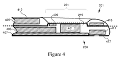
- this figure shows a cross sectional view taken through a vertical centerline of the mated devices 200, 201, illustrating the camera protrusion 219 of the first device 200 keying into the camera hole 221 of the second device 201.
- the interface between the first device 200 and second device 201 is shown by way of a dashed line.
- the first device 200 includes, within its housing 417, a camera 401, camera flash 409, battery 403, display screen 407, and earpiece speaker 411. It will be appreciated that other components such as stand-offs, circuit boards and other features not essential to understanding the disclosure have been omitted for the sake of clarity.
- the second device 201 similarly includes within its housing 419 a battery 405, camera opening 221 and magnet 415 (one of the four magnets 223, 225, 227, 229 discussed with reference to Figure 3 ). Again, components such as stand-offs, circuit boards and other features not essential to understanding the disclosure have been omitted for the sake of clarity.
- Figure 5 illustrates a simplified set of front views of the second device 201, showing the device both with and without a cosmetic sheet 500 covering the magnets.
- the left-most view shows the front 205 of the second device 201 as it appears with the cosmetic sheet 500 applied, hiding the magnets
- the right-most view shows the front 205 of the second device 201 exposed with the cosmetic sheet 500 lifted.
- the cosmetic sheet 500 is shown as semitransparent for ease of understanding, it will be appreciated that the cosmetic sheet 500 need not be semitransparent but may instead be, in whole or in part, transparent, translucent or opaque.
- Figure 6 is a partial cut-away perspective view of the second device 201 in accordance with the described principles.
- the cosmetic sheet 500 can be seen aligned with the circular hole 221 in the second device 201.
- one of the magnets 227 is visible in this view.
- the cosmetic sheet 500 may be printed, imprinted or embossed with brand markings, decorations, instructions or other mateual.
Landscapes
- Engineering & Computer Science (AREA)
- Signal Processing (AREA)
- Human Computer Interaction (AREA)
- Multimedia (AREA)
- Computer Networks & Wireless Communication (AREA)
- Telephone Set Structure (AREA)
- Studio Devices (AREA)
- Stroboscope Apparatuses (AREA)
- Camera Bodies And Camera Details Or Accessories (AREA)
- Accessories Of Cameras (AREA)
Applications Claiming Priority (1)
| Application Number | Priority Date | Filing Date | Title |
|---|---|---|---|
| US14/833,513 US20170064054A1 (en) | 2015-08-24 | 2015-08-24 | Modular Device Docking with Camera Protrusion Alignment |
Publications (1)
| Publication Number | Publication Date |
|---|---|
| EP3136695A1 true EP3136695A1 (de) | 2017-03-01 |
Family
ID=56893689
Family Applications (1)
| Application Number | Title | Priority Date | Filing Date |
|---|---|---|---|
| EP16185008.6A Withdrawn EP3136695A1 (de) | 2015-08-24 | 2016-08-19 | Modulare vorrichtung zum andocken mit kameravorsprungausrichtung |
Country Status (3)
| Country | Link |
|---|---|
| US (1) | US20170064054A1 (de) |
| EP (1) | EP3136695A1 (de) |
| JP (1) | JP2017045043A (de) |
Cited By (4)
| Publication number | Priority date | Publication date | Assignee | Title |
|---|---|---|---|---|
| CN108965691A (zh) * | 2018-06-12 | 2018-12-07 | Oppo广东移动通信有限公司 | 摄像头控制方法、装置、移动终端及存储介质 |
| CN110113513A (zh) * | 2019-03-30 | 2019-08-09 | 联想(北京)有限公司 | 一种电子设备 |
| CN110572568A (zh) * | 2019-08-29 | 2019-12-13 | 维沃移动通信有限公司 | 一种摄像头控制方法及电子设备 |
| WO2020177512A1 (zh) * | 2019-03-01 | 2020-09-10 | 维沃移动通信有限公司 | 终端设备 |
Families Citing this family (7)
| Publication number | Priority date | Publication date | Assignee | Title |
|---|---|---|---|---|
| US10116776B2 (en) | 2015-12-14 | 2018-10-30 | Red.Com, Llc | Modular digital camera and cellular phone |
| CN106850896B (zh) | 2017-03-07 | 2019-12-03 | Oppo广东移动通信有限公司 | 终端 |
| JP6465921B2 (ja) | 2017-04-19 | 2019-02-06 | レノボ・シンガポール・プライベート・リミテッド | ドッキング装置及び電子機器システム |
| EP3481035B1 (de) | 2017-11-03 | 2020-07-29 | Guangdong Oppo Mobile Telecommunications Corp., Ltd. | Versenkbare kamera eines mobilfunktelefons mittels elektromagnetischer kraft |
| CN109862216B (zh) | 2017-11-30 | 2021-06-01 | Oppo广东移动通信有限公司 | 一种摄像头组件、移动终端及其摄像头组件的控制方法 |
| JP7604262B2 (ja) | 2021-02-17 | 2024-12-23 | キヤノン株式会社 | 撮像装置及び撮像装置の制御方法 |
| US11435781B1 (en) * | 2021-03-23 | 2022-09-06 | Lenovo (Singapore) Pte. Ltd. | Computing device |
Citations (6)
| Publication number | Priority date | Publication date | Assignee | Title |
|---|---|---|---|---|
| EP1102456A2 (de) * | 1999-11-18 | 2001-05-23 | Xybernaut Corporation | Persönliches Kommunikationsgerät |
| US20090156199A1 (en) * | 2007-12-18 | 2009-06-18 | Qualcomm Incorporated | Monitoring and troubleshooting a module associated with a portable communication device |
| US20090257203A1 (en) * | 2008-04-14 | 2009-10-15 | Sea-Weng Young | Mobile communication device with replaceable functional modules |
| EP2364005A2 (de) * | 2010-03-05 | 2011-09-07 | Lg Electronics Inc. | Modul zum Erweitern der Funktionsweise eines tragbaren Geräts und tragbares Gerät mit diesem Modul |
| US20120315953A1 (en) * | 2011-06-08 | 2012-12-13 | Zheng Du | Enclosure for image capture systems with focusing capabilities |
| WO2014184610A1 (en) * | 2013-05-13 | 2014-11-20 | Jolla Mobile | Magnetic coupling of an accessory device to a portable electronic device |
Family Cites Families (9)
| Publication number | Priority date | Publication date | Assignee | Title |
|---|---|---|---|---|
| JP3661608B2 (ja) * | 2001-06-11 | 2005-06-15 | コニカミノルタフォトイメージング株式会社 | 携帯電話機に接続して使用するフラッシュ装置 |
| JP2003099178A (ja) * | 2001-09-26 | 2003-04-04 | Sharp Corp | 補助キーボード入力装置及び該装置を装着し得る情報処理装置 |
| JP2007243720A (ja) * | 2006-03-09 | 2007-09-20 | Matsushita Electric Ind Co Ltd | 固定部材および電子機器 |
| WO2008008791A2 (en) * | 2006-07-10 | 2008-01-17 | Aria Enterprises, Inc. | Portable modular multi-function communication device |
| JP5118165B2 (ja) * | 2010-03-04 | 2013-01-16 | ソニーモバイルコミュニケーションズ株式会社 | カメラ撮影画像色調補正装置および携帯端末装置 |
| JP5932301B2 (ja) * | 2011-11-11 | 2016-06-08 | スカラ株式会社 | カメラ用ケース |
| KR102007225B1 (ko) * | 2012-02-16 | 2019-10-21 | 엘지전자 주식회사 | 이동 단말기 |
| JP2014155003A (ja) * | 2013-02-07 | 2014-08-25 | Toei:Kk | 携帯通信端末器用ケース |
| KR102064596B1 (ko) * | 2013-03-11 | 2020-02-11 | 삼성전자 주식회사 | 카메라 모듈을 포함하는 전자장치 |
-
2015
- 2015-08-24 US US14/833,513 patent/US20170064054A1/en not_active Abandoned
-
2016
- 2016-08-02 JP JP2016151806A patent/JP2017045043A/ja active Pending
- 2016-08-19 EP EP16185008.6A patent/EP3136695A1/de not_active Withdrawn
Patent Citations (6)
| Publication number | Priority date | Publication date | Assignee | Title |
|---|---|---|---|---|
| EP1102456A2 (de) * | 1999-11-18 | 2001-05-23 | Xybernaut Corporation | Persönliches Kommunikationsgerät |
| US20090156199A1 (en) * | 2007-12-18 | 2009-06-18 | Qualcomm Incorporated | Monitoring and troubleshooting a module associated with a portable communication device |
| US20090257203A1 (en) * | 2008-04-14 | 2009-10-15 | Sea-Weng Young | Mobile communication device with replaceable functional modules |
| EP2364005A2 (de) * | 2010-03-05 | 2011-09-07 | Lg Electronics Inc. | Modul zum Erweitern der Funktionsweise eines tragbaren Geräts und tragbares Gerät mit diesem Modul |
| US20120315953A1 (en) * | 2011-06-08 | 2012-12-13 | Zheng Du | Enclosure for image capture systems with focusing capabilities |
| WO2014184610A1 (en) * | 2013-05-13 | 2014-11-20 | Jolla Mobile | Magnetic coupling of an accessory device to a portable electronic device |
Cited By (6)
| Publication number | Priority date | Publication date | Assignee | Title |
|---|---|---|---|---|
| CN108965691A (zh) * | 2018-06-12 | 2018-12-07 | Oppo广东移动通信有限公司 | 摄像头控制方法、装置、移动终端及存储介质 |
| WO2020177512A1 (zh) * | 2019-03-01 | 2020-09-10 | 维沃移动通信有限公司 | 终端设备 |
| US11799998B2 (en) | 2019-03-01 | 2023-10-24 | Vivo Mobile Communication Co., Ltd. | Terminal device |
| CN110113513A (zh) * | 2019-03-30 | 2019-08-09 | 联想(北京)有限公司 | 一种电子设备 |
| CN110113513B (zh) * | 2019-03-30 | 2021-08-17 | 联想(北京)有限公司 | 一种电子设备 |
| CN110572568A (zh) * | 2019-08-29 | 2019-12-13 | 维沃移动通信有限公司 | 一种摄像头控制方法及电子设备 |
Also Published As
| Publication number | Publication date |
|---|---|
| JP2017045043A (ja) | 2017-03-02 |
| US20170064054A1 (en) | 2017-03-02 |
Similar Documents
| Publication | Publication Date | Title |
|---|---|---|
| EP3136695A1 (de) | Modulare vorrichtung zum andocken mit kameravorsprungausrichtung | |
| US10317953B2 (en) | Electronic device with moveable contacts at an exterior surface | |
| KR102408795B1 (ko) | 하우징과 동일 평면에서 접촉하는 전자 디바이스 | |
| US11269194B2 (en) | Reflecting module for OIS and camera module including the same | |
| US8073324B2 (en) | Magnet array for coupling and aligning an accessory to an electronic device | |
| US9667760B2 (en) | Module slices in modular portable electronic device | |
| US20210055569A1 (en) | Optical image stabilizing module and camera module including the same | |
| EP3594732A1 (de) | Elektronische bildgebungsvorrichtung | |
| TW201417413A (zh) | 電連接器、托座及電連接器組件 | |
| US10159159B2 (en) | Multifunctional connection systems for various devices and methods of use thereof | |
| CN114600352B (zh) | 马达、摄像模组及移动终端 | |
| CN108833617B (zh) | 移动终端 | |
| CN113395433A (zh) | 摄像模组及电子设备 | |
| US10462345B2 (en) | Deformable structure that compensates for displacement of a camera module of a camera accessory | |
| KR20160113884A (ko) | 전자 장치 및 그의 연결 장치 | |
| US20160234363A1 (en) | Modular Portable Cellular Device Layout and Connection System | |
| CN211378111U (zh) | 电子设备 | |
| CN106291861B (zh) | 相机透镜模块 | |
| US9591766B2 (en) | Portable electronic device contact puck alignment | |
| CN114257715B (zh) | 摄像头的固定装置及方法、终端设备 | |
| CN210839657U (zh) | 一种移动终端 | |
| CN112578860A (zh) | 一种电子设备 | |
| CN216122492U (zh) | 一种手机后盖 | |
| CN101726983A (zh) | 具有照相功能的电子装置 | |
| CN121634652A (zh) | 光圈组件、摄像头模组和电子设备 |
Legal Events
| Date | Code | Title | Description |
|---|---|---|---|
| PUAI | Public reference made under article 153(3) epc to a published international application that has entered the european phase |
Free format text: ORIGINAL CODE: 0009012 |
|
| AK | Designated contracting states |
Kind code of ref document: A1 Designated state(s): AL AT BE BG CH CY CZ DE DK EE ES FI FR GB GR HR HU IE IS IT LI LT LU LV MC MK MT NL NO PL PT RO RS SE SI SK SM TR |
|
| AX | Request for extension of the european patent |
Extension state: BA ME |
|
| 17P | Request for examination filed |
Effective date: 20170901 |
|
| RBV | Designated contracting states (corrected) |
Designated state(s): AL AT BE BG CH CY CZ DE DK EE ES FI FR GB GR HR HU IE IS IT LI LT LU LV MC MK MT NL NO PL PT RO RS SE SI SK SM TR |
|
| 17Q | First examination report despatched |
Effective date: 20180430 |
|
| STAA | Information on the status of an ep patent application or granted ep patent |
Free format text: STATUS: THE APPLICATION IS DEEMED TO BE WITHDRAWN |
|
| 18D | Application deemed to be withdrawn |
Effective date: 20200103 |