EP3136511A2 - Kontaktanordnung, stecker und steckverbindung - Google Patents
Kontaktanordnung, stecker und steckverbindung Download PDFInfo
- Publication number
- EP3136511A2 EP3136511A2 EP16185804.8A EP16185804A EP3136511A2 EP 3136511 A2 EP3136511 A2 EP 3136511A2 EP 16185804 A EP16185804 A EP 16185804A EP 3136511 A2 EP3136511 A2 EP 3136511A2
- Authority
- EP
- European Patent Office
- Prior art keywords
- plug
- affixing
- contact
- contact arrangement
- bar
- Prior art date
- Legal status (The legal status is an assumption and is not a legal conclusion. Google has not performed a legal analysis and makes no representation as to the accuracy of the status listed.)
- Pending
Links
Images


Classifications
-
- H—ELECTRICITY
- H01—ELECTRIC ELEMENTS
- H01R—ELECTRICALLY-CONDUCTIVE CONNECTIONS; STRUCTURAL ASSOCIATIONS OF A PLURALITY OF MUTUALLY-INSULATED ELECTRICAL CONNECTING ELEMENTS; COUPLING DEVICES; CURRENT COLLECTORS
- H01R11/00—Individual connecting elements providing two or more spaced connecting locations for conductive members which are, or may be, thereby interconnected, e.g. end pieces for wires or cables supported by the wire or cable and having means for facilitating electrical connection to some other wire, terminal, or conductive member, blocks of binding posts
- H01R11/11—End pieces or tapping pieces for wires, supported by the wire and for facilitating electrical connection to some other wire, terminal or conductive member
- H01R11/26—End pieces terminating in a screw clamp, screw or nut
-
- H—ELECTRICITY
- H01—ELECTRIC ELEMENTS
- H01R—ELECTRICALLY-CONDUCTIVE CONNECTIONS; STRUCTURAL ASSOCIATIONS OF A PLURALITY OF MUTUALLY-INSULATED ELECTRICAL CONNECTING ELEMENTS; COUPLING DEVICES; CURRENT COLLECTORS
- H01R13/00—Details of coupling devices of the kinds covered by groups H01R12/70 or H01R24/00 - H01R33/00
- H01R13/44—Means for preventing access to live contacts
-
- H—ELECTRICITY
- H01—ELECTRIC ELEMENTS
- H01R—ELECTRICALLY-CONDUCTIVE CONNECTIONS; STRUCTURAL ASSOCIATIONS OF A PLURALITY OF MUTUALLY-INSULATED ELECTRICAL CONNECTING ELEMENTS; COUPLING DEVICES; CURRENT COLLECTORS
- H01R4/00—Electrically-conductive connections between two or more conductive members in direct contact, i.e. touching one another; Means for effecting or maintaining such contact; Electrically-conductive connections having two or more spaced connecting locations for conductors and using contact members penetrating insulation
- H01R4/28—Clamped connections, spring connections
- H01R4/30—Clamped connections, spring connections utilising a screw or nut clamping member
- H01R4/34—Conductive members located under head of screw
-
- H—ELECTRICITY
- H01—ELECTRIC ELEMENTS
- H01R—ELECTRICALLY-CONDUCTIVE CONNECTIONS; STRUCTURAL ASSOCIATIONS OF A PLURALITY OF MUTUALLY-INSULATED ELECTRICAL CONNECTING ELEMENTS; COUPLING DEVICES; CURRENT COLLECTORS
- H01R4/00—Electrically-conductive connections between two or more conductive members in direct contact, i.e. touching one another; Means for effecting or maintaining such contact; Electrically-conductive connections having two or more spaced connecting locations for conductors and using contact members penetrating insulation
- H01R4/70—Insulation of connections
Definitions
- the invention relates to a contact arrangement for a plug for contacting a bus bar with anti-touch protection.
- the invention further relates to a plug with a contact arrangement for a plug connection with a contact arrangement.
- Such contact arrangements usually have an affixing element for securing the contact arrangement to the bus bar, a contact element which has a hole through which the affixing element extends, and a bar-contacting sleeve made of an electrically conductive material for directly contacting the bus bar, wherein the affixing element extends through the bar-contacting sleeve.
- the bar-contacting sleeve allows the bus bar to be contacted despite the anti-touch protection.
- the problem of the invention is to provide a solution which is safer.
- this is solved in that an insulation element which insulates the affixing element from the contact element is arranged between the affixing element and the contact element.
- the affixing element is electrically insulated from the contact element which conducts voltage and current, such that there is no risk of electric shock even if a user touches the affixing element.
- the solution according to the invention is therefore safe. It offers an anti-touch protection not only at the bus bar, but also on the side of the contact element, such that, in the case of a plug connection according to the invention, there is, overall, a two-sided anti-touch protection.
- a plug according to the invention comprises a contact arrangement according to the invention.
- a plug connection according to the invention comprises a plug according to the invention and a bus bar which has anti-touch protection.
- the bar-contacting sleeve can be pressed into the contact element.
- the insulation element can be pressed into the bar-contacting sleeve, in order to enable a permanently stable attachment which in particular minimises the risk of loss. Handling can be simplified as a result.
- an actuation section of the affixing element can be electrically insulated.
- a user or a machine can actuate the affixing element at such an actuation section.
- the affixing element can be surrounded by insulation material in the actuation section, at least in the regions accessible by the user or a machine.
- the insulation material can be configured such that a simple actuation is possible, for example the insulation material can have a tool interface.
- the insulation material can be configured as a screw head, for instance.
- the insulation element can form a retainer for the affixing element.
- a retainer can prevent the affixing element from being lost. This simplifies mounting.
- the retainer can retain the affixing element at least in a friction-locking manner, for example in a premounting position.
- the insulation element forms a guide for the affixing element.
- a guide can restrict the movability of the affixing element substantially to one dimension.
- the insulation element can have a support collar for the affixing element. This can distribute the force coming from the affixing element onto a wide surface. This can lead to smaller deformations by the affixing element, in particular in elements with little mechanical stability.
- the affixing element can be a screw with a head and a bolt and the insulation element can have a support for the head and a channel for the bolt.
- such an insulation element can have a double-L-shaped cross-section.
- a cylindrical section which forms the channel for the bolt can be integral with a disc-shaped section which forms the support for the head.
- the contact arrangement can have a housing part which in a premounting state is open at at least one side, wherein an anti-touch protection finger projects from a housing wall in the direction of the open side.
- the anti-touch protection finger can prevent the penetration of a test finger which is based on the human finger.
- Such an anti-touch protection finger, together with other housing parts, in particular housing walls, can form regions in which such a test finger can penetrate only to such a small extent that touching of current-conducting parts is prohibited.
- the anti-touch protection finger can be kept a certain maximum value away from other housing parts, such as housing walls.
- a plug according to the invention can in particular be an angle plug, i.e. a plug which enables contacting at an angle.
- a plug according to the invention can furthermore have a housing which receives the contact arrangement, and the housing can permit a further anti-touch protection, for example by apertures present therein permitting protection for a test finger. This can be achieved, for instance, through a maximum allowed size of apertures.
- the insulation element can be part of a pressing arrangement which presses the bar-contacting sleeve onto the bus bar. It is possible to dispense with further elements which optimise transmission of the pressing force.
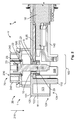
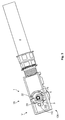
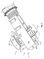
- Figs. 1 to 6 show a plug 35 with a contact arrangement 1 in a premounting position V.
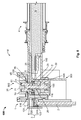
- Figs. 7 to 9 show the plug 35 together with a mating plug 500. These together form a plug connection 600.
- the plug 35 serves to contact a bus bar 2 arranged in the mating plug 500.
- a conductor 18 of a cable 4 is attached to a contact element 5 of the contact arrangement 1.
- the contact element 5 is configured in the form of a cable lug 25.
- a bar-contacting sleeve 29 is attached in a hole 21 in the contact element 5.
- the bar-contacting sleeve 29 is pressed into the contact element 5, such that a good electrical and mechanical connection is produced.
- an anti-touch protection 3 at the mating plug 500 can be overcome and the bus bar 2 can be contacted.
- the anti-touch protection 3 comprises an inner anti-touch protection collar 510 and an outer anti-touch protection collar 520, between which a passage 205 is formed into which a test finger cannot advance up to the bus bar 2.
- the anti-touch protection collars 510, 520 are each configured to be cylindrical.
- An affixing element 22 is present in order to affix the plug 35 to the mating plug 500.
- the affixing element 22 extends through the hole 21 in the contact element 5.
- the affixing element 22, which is configured as a screw 220 by way of example cooperates with a nut 540 which serves as a mating affixing element 550.
- the bar-contacting sleeve 29 is made of electrically conductive material and contacts the bus bar 2 directly.
- the affixing element 22 extends through the bar-contacting sleeve 29. In the mounting position M, the affixing element 22 also extends through the inner anti-touch protection collar 510 of the anti-touch protection 3 at the mating plug 500.
- An insulation element 6 which insulates the affixing element 22 from the contact element 5 is arranged between the affixing element 22 and the contact element 5. If a user mistakenly touches the affixing element 22 in the premounting position V, then he does not get an electric shock, because the affixing element 22 is insulated from the contact element 5. The insulation element 6 also insulates the affixing element 22 from the bar-contacting sleeve 29.
- the insulation element 6 is pressed into the bar-contacting sleeve 29 such that if cannot be lost.
- the insulation element 6 forms a retainer 10 for the affixing element 22. At the same time it forms a guide 11 for the affixing element 22.
- the affixing element 22 is guided along a guide direction 211. Within the retainer 10 and the guide 11, the affixing element 22 has little clearance and cannot touch the interior of the bar-contacting sleeve 29, for example, by tilting.
- the insulation element 6 has a support collar 61 for the affixing element 22. This extends laterally away from a channel 66 which acts as a guide 11 and retainer 10 for the bolt 26 of the screw 220, and has the form of a disc with a hole.
- the support collar 61 forms a support 65 for the head 23 of the screw 220.
- the insulation element 6 is part of a pressing arrangement 560 which in the mounting position M presses the contact element 5 via the bar-contacting sleeve 29 onto the bus bar 2 and as a result produces a good mechanical and electrical contact.
- the support 65 in the form of the support collar 61 distributes the forces, which arise here, uniformly over a wide surface.
- the screw 220 is also, in the mounting position M, electrically insulated from the conductor 18, since the insulation element 6 and the inner anti-touch protection collar 510, which insulate the screw 220 from the contact element 5, the bar-contacting sleeve 29 and the bus bar 2, are arranged around the screw 220.
- an actuation section 70 of the affixing element 22 is electrically insulated at least in the regions accessible by a user. This is achieved by the insulation material 71 being arranged around the head 23 of the screw 220.
- the insulation material 21 itself again forms a head 23 which has a tool interface 230 for an actuating tool.
- the tool interface 230 is configured for actuation with a hexagonal socket.
- a protective ring 240 arranged around the tool interface in particular prevents an actuation with an open-ended wrench.
- the affixing element 22 is undetachably attached to a housing part 120.
- a protrusion 310 of that part of the head 23 which is made of insulation material 71 projects to the side and cooperates with several engagement hooks 320 at the housing part 121.
- the housing part 120 In the premounting position V, the housing part 120 has an open side 124, at which the contacting to the mating plug 500 takes place. In order to prevent contacting with a finger here, an anti-touch protection arrangement 102 is present.
- the anti-touch protection arrangement 102 has anti-touch protection elements 105 in the form of protruding collar elements. Such an anti-touch protection element 105 is also arranged at an additional housing part 140 which can be connected to the housing part 120. Since, in particular, a contacting of the contact element 5 between the affixing element 22 and a front wall 122 spaced apart therefrom would be possible if only the anti-touch protection elements 105 were present, the anti-touch protection 102 further possesses an anti-touch protection finger 110.
- the anti-touch protection finger 110 projects from a cover wall 121 toward the open side 124. There is not sufficient space between the anti-touch protection finger 110 and the front wall 122, as well as side walls 123, to introduce a test finger up to the contact element 5.
- the shown plug connection 600 has a two-sided anti-touch protection, i.e. on the one hand anti-touch protection at the plug 35, and an anti-touch protection at the mating plug 500 on the other hand.
Landscapes
- Details Of Connecting Devices For Male And Female Coupling (AREA)
- Fuses (AREA)
- Installation Of Bus-Bars (AREA)
- Connector Housings Or Holding Contact Members (AREA)
Applications Claiming Priority (1)
| Application Number | Priority Date | Filing Date | Title |
|---|---|---|---|
| DE102015216543.4A DE102015216543A1 (de) | 2015-08-28 | 2015-08-28 | Kontaktanordnung, Stecker und Steckverbindung |
Publications (2)
| Publication Number | Publication Date |
|---|---|
| EP3136511A2 true EP3136511A2 (de) | 2017-03-01 |
| EP3136511A3 EP3136511A3 (de) | 2017-03-08 |
Family
ID=56802343
Family Applications (1)
| Application Number | Title | Priority Date | Filing Date |
|---|---|---|---|
| EP16185804.8A Pending EP3136511A3 (de) | 2015-08-28 | 2016-08-26 | Kontaktanordnung, stecker und steckverbindung |
Country Status (2)
| Country | Link |
|---|---|
| EP (1) | EP3136511A3 (de) |
| DE (1) | DE102015216543A1 (de) |
Cited By (7)
| Publication number | Priority date | Publication date | Assignee | Title |
|---|---|---|---|---|
| JP2018200864A (ja) * | 2017-04-11 | 2018-12-20 | ヤザキ・ヨーロッパ・リミテッド | 電気接続装置 |
| EP3419119A1 (de) * | 2017-06-21 | 2018-12-26 | TE Connectivity Germany GmbH | Modulverbinder |
| WO2021213928A1 (de) * | 2020-04-20 | 2021-10-28 | Hirschmann Automotive Gmbh | Steckverbinder mit schraubverbindung |
| CN113826285A (zh) * | 2019-05-24 | 2021-12-21 | 株式会社自动网络技术研究所 | 端子间连接结构 |
| WO2022073945A1 (de) * | 2020-10-09 | 2022-04-14 | Leoni Bordnetz-Systeme Gmbh | Kontaktverbinder |
| CN114649721A (zh) * | 2020-12-18 | 2022-06-21 | 泰连德国有限公司 | 用于附接到汇流条的汇流条接触件以及用于附接汇流条接触件的方法 |
| CN115411544A (zh) * | 2021-05-27 | 2022-11-29 | 泰连德国有限公司 | 具有摩擦配合接触元件的接触组件以及模块连接器 |
Families Citing this family (7)
| Publication number | Priority date | Publication date | Assignee | Title |
|---|---|---|---|---|
| DE102017131223B4 (de) * | 2017-12-22 | 2025-04-30 | Otto Bock Healthcare Products Gmbh | Steckersystem |
| DE102021123635A1 (de) * | 2021-09-13 | 2023-03-16 | Te Connectivity Germany Gmbh | Hochstromverbindungs-Spannschraubenvorrichtung sowie elektrischer Hochstromverbinder und Hochstrom-Leitungsverbinder |
| DE102022132899A1 (de) | 2022-12-12 | 2024-06-13 | Audi Aktiengesellschaft | Verbinder |
| DE102022004927A1 (de) | 2022-12-30 | 2024-07-11 | Mercedes-Benz Group AG | Vorrichtung zum Herstellen einer elektrischen Verbindung |
| DE102023112888A1 (de) | 2023-05-16 | 2024-11-21 | Audi Aktiengesellschaft | Gehäuse für einen Modulpolanschluss zur Bereitstellung eines Berührschutzes, Modulpolanschluss, Verbindungsanordnung und Batteriemodul für ein Kraftfahrzeug |
| DE102023119845B3 (de) | 2023-07-26 | 2024-10-10 | Amphenol-Tuchel Electronics Gesellschaft mit beschränkter Haftung | Stromschiene-Steckkontaktpin-Verbindung |
| DE102024106521A1 (de) * | 2024-03-07 | 2025-09-11 | Amphenol-Tuchel Electronics Gesellschaft mit beschränkter Haftung | Stromschiene-Steckkontaktpin-Verbindung |
Family Cites Families (5)
| Publication number | Priority date | Publication date | Assignee | Title |
|---|---|---|---|---|
| US4066324A (en) * | 1977-02-11 | 1978-01-03 | Valor Enterprises, Inc. | Solderless coaxial cable terminator |
| US5580277A (en) * | 1994-11-15 | 1996-12-03 | Solar Conversion Corp. | Antenna cable connector |
| EP2671287B1 (de) * | 2011-02-03 | 2018-05-09 | Volvo Construction Equipment AB | Verfahren zur bereitstellung einer elektrischen verbindungsanordnung und elektrische verbindungsanordnung |
| DE102013005109B4 (de) * | 2013-03-23 | 2020-06-25 | Audi Ag | Verbindervorrichtung zum mechanischen Verbinden einer Kabelvorrichtung mit einer elektrisch leitenden Komponente sowie mit der Verbindervorrichtung kuppelbare Kabelvorrichtung |
| DE102014203128B4 (de) * | 2014-02-21 | 2021-03-25 | Bayerische Motoren Werke Aktiengesellschaft | Elektrische Verbindungsvorrichtung, insbesondere zur elektrischen Hochvoltverbindung, aus zwei Verbindungselementen |
-
2015
- 2015-08-28 DE DE102015216543.4A patent/DE102015216543A1/de active Pending
-
2016
- 2016-08-26 EP EP16185804.8A patent/EP3136511A3/de active Pending
Non-Patent Citations (1)
| Title |
|---|
| None |
Cited By (17)
| Publication number | Priority date | Publication date | Assignee | Title |
|---|---|---|---|---|
| JP2018200864A (ja) * | 2017-04-11 | 2018-12-20 | ヤザキ・ヨーロッパ・リミテッド | 電気接続装置 |
| US10205274B2 (en) * | 2017-04-11 | 2019-02-12 | Yazaki Europe Ltd. | Electronic connection arrangement |
| EP3419119A1 (de) * | 2017-06-21 | 2018-12-26 | TE Connectivity Germany GmbH | Modulverbinder |
| CN109103613A (zh) * | 2017-06-21 | 2018-12-28 | 泰连德国有限公司 | 模块连接器 |
| CN111710998A (zh) * | 2017-06-21 | 2020-09-25 | 泰连德国有限公司 | 模块连接器 |
| CN109103613B (zh) * | 2017-06-21 | 2020-11-10 | 泰连德国有限公司 | 模块连接器 |
| CN113826285B (zh) * | 2019-05-24 | 2024-05-28 | 株式会社自动网络技术研究所 | 端子间连接结构 |
| CN113826285A (zh) * | 2019-05-24 | 2021-12-21 | 株式会社自动网络技术研究所 | 端子间连接结构 |
| CN115428263A (zh) * | 2020-04-20 | 2022-12-02 | 赫斯曼汽车有限公司 | 带有螺纹连接的插接连接器 |
| WO2021213928A1 (de) * | 2020-04-20 | 2021-10-28 | Hirschmann Automotive Gmbh | Steckverbinder mit schraubverbindung |
| WO2022073945A1 (de) * | 2020-10-09 | 2022-04-14 | Leoni Bordnetz-Systeme Gmbh | Kontaktverbinder |
| CN114649721A (zh) * | 2020-12-18 | 2022-06-21 | 泰连德国有限公司 | 用于附接到汇流条的汇流条接触件以及用于附接汇流条接触件的方法 |
| US12155162B2 (en) | 2020-12-18 | 2024-11-26 | Te Connectivity Germany Gmbh | Bus bar contact for attachment to a bus bar, and method for attaching a bus bar contact |
| CN114649721B (zh) * | 2020-12-18 | 2024-12-03 | 泰连德国有限公司 | 用于附接到汇流条的汇流条接触件以及用于附接汇流条接触件的方法 |
| CN115411544A (zh) * | 2021-05-27 | 2022-11-29 | 泰连德国有限公司 | 具有摩擦配合接触元件的接触组件以及模块连接器 |
| US20220384911A1 (en) * | 2021-05-27 | 2022-12-01 | Te Connectivity Germany Gmbh | Contact Assembly with a Frictionally Mated Contact Element as well as Module Connector, Connection Assembly, Battery Cell and Battery Module with such Contact Assemblies |
| JP2022183067A (ja) * | 2021-05-27 | 2022-12-08 | ティーイー コネクティビティ ジャーマニー ゲゼルシャフト ミット ベシュレンクテル ハフツンク | 摩擦により装着されたコンタクト要素を有するコンタクトアセンブリ、ならびにそのようなコンタクトアセンブリを有するモジュールコネクタ、接続アセンブリ、バッテリセルおよびバッテリモジュール |
Also Published As
| Publication number | Publication date |
|---|---|
| EP3136511A3 (de) | 2017-03-08 |
| DE102015216543A1 (de) | 2017-03-02 |
Similar Documents
| Publication | Publication Date | Title |
|---|---|---|
| EP3136511A2 (de) | Kontaktanordnung, stecker und steckverbindung | |
| US10476180B2 (en) | Connector for the connection of two electrical conductors | |
| US10381752B2 (en) | Module connector | |
| EP3145035B1 (de) | Anordnung zur herstellung einer elektrischen verbindung zwischen einem flachsteckerkontakt und einem hochstromleiter | |
| JP6638014B2 (ja) | 電気接続装置 | |
| US8696376B2 (en) | Cable connection system and method for connecting a cable to a cable connection system | |
| EP3726661B1 (de) | Hochspannungsfingerschutz | |
| JP4674687B2 (ja) | 電動端子用橋絡体 | |
| EP3584889B1 (de) | Verbindervorrichtung | |
| US10608380B2 (en) | Connector | |
| EP3252872B1 (de) | Verbindungskäfig zur verbindung von zwei elektroflachkontakten und stecksystem,das beides enthält | |
| JP3899310B2 (ja) | 電気的な接触部材 | |
| JP6583323B2 (ja) | 配線用接続器具、及び電気機器 | |
| JP2012169273A (ja) | 万能コネクタソケット | |
| EP3145034B1 (de) | Elektrische verbindungsanordnung mit einem elektrischen verbinder und einem gegensteckverbinder | |
| KR20130121031A (ko) | 전자의료 디바이스용 소켓 장치 | |
| EP3046186B1 (de) | Anordnung zur verbindung von zwei elektrischen leitern | |
| US20110312208A1 (en) | Push-in connector for accepting the end of a rigid conductor | |
| US20110086556A1 (en) | Electrical connector with cam actuated locking mechanism | |
| KR101865009B1 (ko) | 플러그 | |
| RU2653167C2 (ru) | Соединитель термопары, приспособленный для соединения газового предохранительного клапана и термопары | |
| JP4021892B2 (ja) | 丸型差込接続器におけるエレメントの配置構造 | |
| CN105745791A (zh) | 具有护套夹的电连接器 | |
| KR101580792B1 (ko) | 절연관통형 리드선 접속 전력용 피뢰기 | |
| KR101205016B1 (ko) | 전원 연결 기구 |
Legal Events
| Date | Code | Title | Description |
|---|---|---|---|
| PUAI | Public reference made under article 153(3) epc to a published international application that has entered the european phase |
Free format text: ORIGINAL CODE: 0009012 |
|
| STAA | Information on the status of an ep patent application or granted ep patent |
Free format text: STATUS: THE APPLICATION HAS BEEN PUBLISHED |
|
| PUAL | Search report despatched |
Free format text: ORIGINAL CODE: 0009013 |
|
| AK | Designated contracting states |
Kind code of ref document: A2 Designated state(s): AL AT BE BG CH CY CZ DE DK EE ES FI FR GB GR HR HU IE IS IT LI LT LU LV MC MK MT NL NO PL PT RO RS SE SI SK SM TR |
|
| AX | Request for extension of the european patent |
Extension state: BA ME |
|
| AK | Designated contracting states |
Kind code of ref document: A3 Designated state(s): AL AT BE BG CH CY CZ DE DK EE ES FI FR GB GR HR HU IE IS IT LI LT LU LV MC MK MT NL NO PL PT RO RS SE SI SK SM TR |
|
| AX | Request for extension of the european patent |
Extension state: BA ME |
|
| RIC1 | Information provided on ipc code assigned before grant |
Ipc: H01R 13/44 20060101AFI20170127BHEP Ipc: H01R 13/621 20060101ALI20170127BHEP |
|
| STAA | Information on the status of an ep patent application or granted ep patent |
Free format text: STATUS: REQUEST FOR EXAMINATION WAS MADE |
|
| 17P | Request for examination filed |
Effective date: 20170614 |
|
| RBV | Designated contracting states (corrected) |
Designated state(s): AL AT BE BG CH CY CZ DE DK EE ES FI FR GB GR HR HU IE IS IT LI LT LU LV MC MK MT NL NO PL PT RO RS SE SI SK SM TR |
|
| STAA | Information on the status of an ep patent application or granted ep patent |
Free format text: STATUS: EXAMINATION IS IN PROGRESS |
|
| 17Q | First examination report despatched |
Effective date: 20180713 |
|
| REG | Reference to a national code |
Ref country code: DE Ref legal event code: R079 Free format text: PREVIOUS MAIN CLASS: H01R0004300000 Ipc: H01R0004340000 |
|
| RIC1 | Information provided on ipc code assigned before grant |
Ipc: H01R 13/44 20060101ALI20241018BHEP Ipc: H01R 11/26 20060101ALI20241018BHEP Ipc: H01R 4/70 20060101ALI20241018BHEP Ipc: H01R 4/34 20060101AFI20241018BHEP |
|
| GRAP | Despatch of communication of intention to grant a patent |
Free format text: ORIGINAL CODE: EPIDOSNIGR1 |
|
| STAA | Information on the status of an ep patent application or granted ep patent |
Free format text: STATUS: GRANT OF PATENT IS INTENDED |
|
| INTG | Intention to grant announced |
Effective date: 20251007 |