EP3136511A2 - Contact arrangement, plug and plug connection - Google Patents
Contact arrangement, plug and plug connection Download PDFInfo
- Publication number
- EP3136511A2 EP3136511A2 EP16185804.8A EP16185804A EP3136511A2 EP 3136511 A2 EP3136511 A2 EP 3136511A2 EP 16185804 A EP16185804 A EP 16185804A EP 3136511 A2 EP3136511 A2 EP 3136511A2
- Authority
- EP
- European Patent Office
- Prior art keywords
- plug
- affixing
- contact
- contact arrangement
- bar
- Prior art date
- Legal status (The legal status is an assumption and is not a legal conclusion. Google has not performed a legal analysis and makes no representation as to the accuracy of the status listed.)
- Pending
Links
Images


Classifications
-
- H—ELECTRICITY
- H01—ELECTRIC ELEMENTS
- H01R—ELECTRICALLY-CONDUCTIVE CONNECTIONS; STRUCTURAL ASSOCIATIONS OF A PLURALITY OF MUTUALLY-INSULATED ELECTRICAL CONNECTING ELEMENTS; COUPLING DEVICES; CURRENT COLLECTORS
- H01R13/00—Details of coupling devices of the kinds covered by groups H01R12/70 or H01R24/00 - H01R33/00
- H01R13/44—Means for preventing access to live contacts
-
- H—ELECTRICITY
- H01—ELECTRIC ELEMENTS
- H01R—ELECTRICALLY-CONDUCTIVE CONNECTIONS; STRUCTURAL ASSOCIATIONS OF A PLURALITY OF MUTUALLY-INSULATED ELECTRICAL CONNECTING ELEMENTS; COUPLING DEVICES; CURRENT COLLECTORS
- H01R13/00—Details of coupling devices of the kinds covered by groups H01R12/70 or H01R24/00 - H01R33/00
- H01R13/62—Means for facilitating engagement or disengagement of coupling parts or for holding them in engagement
- H01R13/621—Bolt, set screw or screw clamp
Definitions
- the invention relates to a contact arrangement for a plug for contacting a bus bar with anti-touch protection.
- the invention further relates to a plug with a contact arrangement for a plug connection with a contact arrangement.
- Such contact arrangements usually have an affixing element for securing the contact arrangement to the bus bar, a contact element which has a hole through which the affixing element extends, and a bar-contacting sleeve made of an electrically conductive material for directly contacting the bus bar, wherein the affixing element extends through the bar-contacting sleeve.
- the bar-contacting sleeve allows the bus bar to be contacted despite the anti-touch protection.
- the problem of the invention is to provide a solution which is safer.
- this is solved in that an insulation element which insulates the affixing element from the contact element is arranged between the affixing element and the contact element.
- the affixing element is electrically insulated from the contact element which conducts voltage and current, such that there is no risk of electric shock even if a user touches the affixing element.
- the solution according to the invention is therefore safe. It offers an anti-touch protection not only at the bus bar, but also on the side of the contact element, such that, in the case of a plug connection according to the invention, there is, overall, a two-sided anti-touch protection.
- a plug according to the invention comprises a contact arrangement according to the invention.
- a plug connection according to the invention comprises a plug according to the invention and a bus bar which has anti-touch protection.
- the bar-contacting sleeve can be pressed into the contact element.
- the insulation element can be pressed into the bar-contacting sleeve, in order to enable a permanently stable attachment which in particular minimises the risk of loss. Handling can be simplified as a result.
- an actuation section of the affixing element can be electrically insulated.
- a user or a machine can actuate the affixing element at such an actuation section.
- the affixing element can be surrounded by insulation material in the actuation section, at least in the regions accessible by the user or a machine.
- the insulation material can be configured such that a simple actuation is possible, for example the insulation material can have a tool interface.
- the insulation material can be configured as a screw head, for instance.
- the insulation element can form a retainer for the affixing element.
- a retainer can prevent the affixing element from being lost. This simplifies mounting.
- the retainer can retain the affixing element at least in a friction-locking manner, for example in a premounting position.
- the insulation element forms a guide for the affixing element.
- a guide can restrict the movability of the affixing element substantially to one dimension.
- the insulation element can have a support collar for the affixing element. This can distribute the force coming from the affixing element onto a wide surface. This can lead to smaller deformations by the affixing element, in particular in elements with little mechanical stability.
- the affixing element can be a screw with a head and a bolt and the insulation element can have a support for the head and a channel for the bolt.
- such an insulation element can have a double-L-shaped cross-section.
- a cylindrical section which forms the channel for the bolt can be integral with a disc-shaped section which forms the support for the head.
- the contact arrangement can have a housing part which in a premounting state is open at at least one side, wherein an anti-touch protection finger projects from a housing wall in the direction of the open side.
- the anti-touch protection finger can prevent the penetration of a test finger which is based on the human finger.
- Such an anti-touch protection finger, together with other housing parts, in particular housing walls, can form regions in which such a test finger can penetrate only to such a small extent that touching of current-conducting parts is prohibited.
- the anti-touch protection finger can be kept a certain maximum value away from other housing parts, such as housing walls.
- a plug according to the invention can in particular be an angle plug, i.e. a plug which enables contacting at an angle.
- a plug according to the invention can furthermore have a housing which receives the contact arrangement, and the housing can permit a further anti-touch protection, for example by apertures present therein permitting protection for a test finger. This can be achieved, for instance, through a maximum allowed size of apertures.
- the insulation element can be part of a pressing arrangement which presses the bar-contacting sleeve onto the bus bar. It is possible to dispense with further elements which optimise transmission of the pressing force.
- Figs. 1 to 6 show a plug 35 with a contact arrangement 1 in a premounting position V.
- Figs. 7 to 9 show the plug 35 together with a mating plug 500. These together form a plug connection 600.
- the plug 35 serves to contact a bus bar 2 arranged in the mating plug 500.
- a conductor 18 of a cable 4 is attached to a contact element 5 of the contact arrangement 1.
- the contact element 5 is configured in the form of a cable lug 25.
- a bar-contacting sleeve 29 is attached in a hole 21 in the contact element 5.
- the bar-contacting sleeve 29 is pressed into the contact element 5, such that a good electrical and mechanical connection is produced.
- an anti-touch protection 3 at the mating plug 500 can be overcome and the bus bar 2 can be contacted.
- the anti-touch protection 3 comprises an inner anti-touch protection collar 510 and an outer anti-touch protection collar 520, between which a passage 205 is formed into which a test finger cannot advance up to the bus bar 2.
- the anti-touch protection collars 510, 520 are each configured to be cylindrical.
- An affixing element 22 is present in order to affix the plug 35 to the mating plug 500.
- the affixing element 22 extends through the hole 21 in the contact element 5.
- the affixing element 22, which is configured as a screw 220 by way of example cooperates with a nut 540 which serves as a mating affixing element 550.
- the bar-contacting sleeve 29 is made of electrically conductive material and contacts the bus bar 2 directly.
- the affixing element 22 extends through the bar-contacting sleeve 29. In the mounting position M, the affixing element 22 also extends through the inner anti-touch protection collar 510 of the anti-touch protection 3 at the mating plug 500.
- An insulation element 6 which insulates the affixing element 22 from the contact element 5 is arranged between the affixing element 22 and the contact element 5. If a user mistakenly touches the affixing element 22 in the premounting position V, then he does not get an electric shock, because the affixing element 22 is insulated from the contact element 5. The insulation element 6 also insulates the affixing element 22 from the bar-contacting sleeve 29.
- the insulation element 6 is pressed into the bar-contacting sleeve 29 such that if cannot be lost.
- the insulation element 6 forms a retainer 10 for the affixing element 22. At the same time it forms a guide 11 for the affixing element 22.
- the affixing element 22 is guided along a guide direction 211. Within the retainer 10 and the guide 11, the affixing element 22 has little clearance and cannot touch the interior of the bar-contacting sleeve 29, for example, by tilting.
- the insulation element 6 has a support collar 61 for the affixing element 22. This extends laterally away from a channel 66 which acts as a guide 11 and retainer 10 for the bolt 26 of the screw 220, and has the form of a disc with a hole.
- the support collar 61 forms a support 65 for the head 23 of the screw 220.
- the insulation element 6 is part of a pressing arrangement 560 which in the mounting position M presses the contact element 5 via the bar-contacting sleeve 29 onto the bus bar 2 and as a result produces a good mechanical and electrical contact.
- the support 65 in the form of the support collar 61 distributes the forces, which arise here, uniformly over a wide surface.
- the screw 220 is also, in the mounting position M, electrically insulated from the conductor 18, since the insulation element 6 and the inner anti-touch protection collar 510, which insulate the screw 220 from the contact element 5, the bar-contacting sleeve 29 and the bus bar 2, are arranged around the screw 220.
- an actuation section 70 of the affixing element 22 is electrically insulated at least in the regions accessible by a user. This is achieved by the insulation material 71 being arranged around the head 23 of the screw 220.
- the insulation material 21 itself again forms a head 23 which has a tool interface 230 for an actuating tool.
- the tool interface 230 is configured for actuation with a hexagonal socket.
- a protective ring 240 arranged around the tool interface in particular prevents an actuation with an open-ended wrench.
- the affixing element 22 is undetachably attached to a housing part 120.
- a protrusion 310 of that part of the head 23 which is made of insulation material 71 projects to the side and cooperates with several engagement hooks 320 at the housing part 121.
- the housing part 120 In the premounting position V, the housing part 120 has an open side 124, at which the contacting to the mating plug 500 takes place. In order to prevent contacting with a finger here, an anti-touch protection arrangement 102 is present.
- the anti-touch protection arrangement 102 has anti-touch protection elements 105 in the form of protruding collar elements. Such an anti-touch protection element 105 is also arranged at an additional housing part 140 which can be connected to the housing part 120. Since, in particular, a contacting of the contact element 5 between the affixing element 22 and a front wall 122 spaced apart therefrom would be possible if only the anti-touch protection elements 105 were present, the anti-touch protection 102 further possesses an anti-touch protection finger 110.
- the anti-touch protection finger 110 projects from a cover wall 121 toward the open side 124. There is not sufficient space between the anti-touch protection finger 110 and the front wall 122, as well as side walls 123, to introduce a test finger up to the contact element 5.
- the shown plug connection 600 has a two-sided anti-touch protection, i.e. on the one hand anti-touch protection at the plug 35, and an anti-touch protection at the mating plug 500 on the other hand.
Abstract
Description
- The invention relates to a contact arrangement for a plug for contacting a bus bar with anti-touch protection. The invention further relates to a plug with a contact arrangement for a plug connection with a contact arrangement.
- Such contact arrangements usually have an affixing element for securing the contact arrangement to the bus bar, a contact element which has a hole through which the affixing element extends, and a bar-contacting sleeve made of an electrically conductive material for directly contacting the bus bar, wherein the affixing element extends through the bar-contacting sleeve. The bar-contacting sleeve allows the bus bar to be contacted despite the anti-touch protection.
- A disadvantage in the stated contact arrangements is that there is a risk of electric shock for the user in the event of faulty operation
- The problem of the invention is to provide a solution which is safer.
- According to the invention, this is solved in that an insulation element which insulates the affixing element from the contact element is arranged between the affixing element and the contact element.
- In this solution, the affixing element is electrically insulated from the contact element which conducts voltage and current, such that there is no risk of electric shock even if a user touches the affixing element. The solution according to the invention is therefore safe. It offers an anti-touch protection not only at the bus bar, but also on the side of the contact element, such that, in the case of a plug connection according to the invention, there is, overall, a two-sided anti-touch protection.
- A plug according to the invention comprises a contact arrangement according to the invention. A plug connection according to the invention comprises a plug according to the invention and a bus bar which has anti-touch protection.
- The solution according to the invention can be further improved with the following configurations and further developments which are advantageous per se.
- In order to enable safe attachment which is in particular long-term stable and which has a low transition resistance, the bar-contacting sleeve can be pressed into the contact element.
- Furthermore, in one advantageous configuration, the insulation element can be pressed into the bar-contacting sleeve, in order to enable a permanently stable attachment which in particular minimises the risk of loss. Handling can be simplified as a result.
- In order to further improve safety, an actuation section of the affixing element can be electrically insulated. A user or a machine can actuate the affixing element at such an actuation section. The affixing element can be surrounded by insulation material in the actuation section, at least in the regions accessible by the user or a machine. In this case, the insulation material can be configured such that a simple actuation is possible, for example the insulation material can have a tool interface. The insulation material can be configured as a screw head, for instance.
- In one advantageous configuration, the insulation element can form a retainer for the affixing element. Such a retainer can prevent the affixing element from being lost. This simplifies mounting. The retainer can retain the affixing element at least in a friction-locking manner, for example in a premounting position.
- In a further advantageous configuration, the insulation element forms a guide for the affixing element. As a result, it is possible to dispense with further elements such as an additional guide element. A guide can restrict the movability of the affixing element substantially to one dimension. As a result, it is possible to restrict unintentional movement of the affixing element which leads to a possible contact with a current-carrying element. If a guide is also a retainer, the greatest possible safety is obtained as a result, through an extensive restriction of the movement of the affixing element.
- To obtain a good distribution of force, the insulation element can have a support collar for the affixing element. This can distribute the force coming from the affixing element onto a wide surface. This can lead to smaller deformations by the affixing element, in particular in elements with little mechanical stability.
- In a solution which is simple to implement, the affixing element can be a screw with a head and a bolt and the insulation element can have a support for the head and a channel for the bolt. In a simple configuration, such an insulation element can have a double-L-shaped cross-section. A cylindrical section which forms the channel for the bolt can be integral with a disc-shaped section which forms the support for the head.
- In order to enable touching of current-carrying parts, even from one side at which contacting with a plug takes place, the contact arrangement can have a housing part which in a premounting state is open at at least one side, wherein an anti-touch protection finger projects from a housing wall in the direction of the open side. The anti-touch protection finger can prevent the penetration of a test finger which is based on the human finger. Such an anti-touch protection finger, together with other housing parts, in particular housing walls, can form regions in which such a test finger can penetrate only to such a small extent that touching of current-conducting parts is prohibited. For this purpose, the anti-touch protection finger can be kept a certain maximum value away from other housing parts, such as housing walls.
- A plug according to the invention can in particular be an angle plug, i.e. a plug which enables contacting at an angle. A plug according to the invention can furthermore have a housing which receives the contact arrangement, and the housing can permit a further anti-touch protection, for example by apertures present therein permitting protection for a test finger. This can be achieved, for instance, through a maximum allowed size of apertures.
- In a plug connection according to the invention, the insulation element can be part of a pressing arrangement which presses the bar-contacting sleeve onto the bus bar. It is possible to dispense with further elements which optimise transmission of the pressing force.
- Hereafter, the application will be explained in greater detail using advantageous configurations with reference to the drawings. The features thus shown are each independent of one another and can be combined with one another as desired, as required depending on the application.
- In the drawings:
- Fig. 1
- shows a schematic perspective view of a plug according to the invention;
- Fig. 2
- shows a longitudinal section through the plug from
Fig. 1 ; - Fig. 3
- shows a schematic perspective view of the plug from
Figs. 1 and2 ; - Fig. 4
- shows a further schematic perspective view of the plug from
Figs. 1 to 3 ; - Fig. 5
- shows a further schematic perspective view of the plug from
Figs. 1 to 4 ; - Fig. 6
- shows a further schematic perspective view of the plug from
Figs. 1 to 5 ; - Fig. 7
- shows a schematic perspective view of a plug connection with the plug from
Figs. 1 to 6 ; - Fig. 8
- shows a longitudinal section through the plug connection from
Fig. 7 ; - Fig. 9
- shows a further schematic perspective view of the plug connection from
Figs. 7 and8 . -
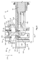
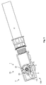
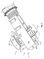
Figs. 1 to 6 show aplug 35 with acontact arrangement 1 in a premounting position V.Figs. 7 to 9 show theplug 35 together with amating plug 500. These together form aplug connection 600. - The
plug 35 serves to contact abus bar 2 arranged in themating plug 500. Aconductor 18 of acable 4 is attached to acontact element 5 of thecontact arrangement 1. Thecontact element 5 is configured in the form of acable lug 25. - A bar-contacting
sleeve 29 is attached in ahole 21 in thecontact element 5. The bar-contactingsleeve 29 is pressed into thecontact element 5, such that a good electrical and mechanical connection is produced. With the bar-contactingsleeve 29, ananti-touch protection 3 at themating plug 500 can be overcome and thebus bar 2 can be contacted. Theanti-touch protection 3 comprises an inneranti-touch protection collar 510 and an outeranti-touch protection collar 520, between which apassage 205 is formed into which a test finger cannot advance up to thebus bar 2. Theanti-touch protection collars - An affixing
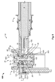
element 22 is present in order to affix theplug 35 to themating plug 500. The affixingelement 22 extends through thehole 21 in thecontact element 5. In the mounting position M shown inFigs. 7 to 9 , the affixingelement 22, which is configured as a screw 220 by way of example, cooperates with anut 540 which serves as a mating affixing element 550. - The bar-contacting
sleeve 29 is made of electrically conductive material and contacts thebus bar 2 directly. The affixingelement 22 extends through the bar-contactingsleeve 29. In the mounting position M, the affixingelement 22 also extends through the inneranti-touch protection collar 510 of theanti-touch protection 3 at themating plug 500. - An
insulation element 6 which insulates the affixingelement 22 from thecontact element 5 is arranged between the affixingelement 22 and thecontact element 5. If a user mistakenly touches the affixingelement 22 in the premounting position V, then he does not get an electric shock, because the affixingelement 22 is insulated from thecontact element 5. Theinsulation element 6 also insulates the affixingelement 22 from the bar-contactingsleeve 29. - The
insulation element 6 is pressed into the bar-contactingsleeve 29 such that if cannot be lost. - The
insulation element 6 forms aretainer 10 for the affixingelement 22. At the same time it forms aguide 11 for the affixingelement 22. The affixingelement 22 is guided along aguide direction 211. Within theretainer 10 and theguide 11, the affixingelement 22 has little clearance and cannot touch the interior of the bar-contactingsleeve 29, for example, by tilting. - The
insulation element 6 has asupport collar 61 for the affixingelement 22. This extends laterally away from achannel 66 which acts as aguide 11 andretainer 10 for thebolt 26 of the screw 220, and has the form of a disc with a hole. Thesupport collar 61 forms asupport 65 for thehead 23 of the screw 220. - The
insulation element 6 is part of apressing arrangement 560 which in the mounting position M presses thecontact element 5 via the bar-contactingsleeve 29 onto thebus bar 2 and as a result produces a good mechanical and electrical contact. Thesupport 65 in the form of thesupport collar 61 distributes the forces, which arise here, uniformly over a wide surface. - In the embodiment shown, the screw 220 is also, in the mounting position M, electrically insulated from the
conductor 18, since theinsulation element 6 and the inneranti-touch protection collar 510, which insulate the screw 220 from thecontact element 5, the bar-contactingsleeve 29 and thebus bar 2, are arranged around the screw 220. - In order to permit even safer operation, for example if the
insulation element 6 is not present or should be defective, anactuation section 70 of the affixingelement 22 is electrically insulated at least in the regions accessible by a user. This is achieved by theinsulation material 71 being arranged around thehead 23 of the screw 220. Theinsulation material 21 itself again forms ahead 23 which has atool interface 230 for an actuating tool. In the case shown, thetool interface 230 is configured for actuation with a hexagonal socket. Aprotective ring 240 arranged around the tool interface in particular prevents an actuation with an open-ended wrench. - The affixing
element 22 is undetachably attached to ahousing part 120. For this purpose, aprotrusion 310 of that part of thehead 23 which is made ofinsulation material 71 projects to the side and cooperates with several engagement hooks 320 at thehousing part 121. - In the premounting position V, the
housing part 120 has anopen side 124, at which the contacting to themating plug 500 takes place. In order to prevent contacting with a finger here, ananti-touch protection arrangement 102 is present. - The
anti-touch protection arrangement 102 hasanti-touch protection elements 105 in the form of protruding collar elements. Such ananti-touch protection element 105 is also arranged at anadditional housing part 140 which can be connected to thehousing part 120. Since, in particular, a contacting of thecontact element 5 between the affixingelement 22 and afront wall 122 spaced apart therefrom would be possible if only theanti-touch protection elements 105 were present, theanti-touch protection 102 further possesses ananti-touch protection finger 110. Theanti-touch protection finger 110 projects from acover wall 121 toward theopen side 124. There is not sufficient space between theanti-touch protection finger 110 and thefront wall 122, as well asside walls 123, to introduce a test finger up to thecontact element 5. - The shown
plug connection 600 has a two-sided anti-touch protection, i.e. on the one hand anti-touch protection at theplug 35, and an anti-touch protection at themating plug 500 on the other hand. -
- 1
- contact arrangement
- 2
- bus bar
- 3
- anti-touch protection
- 4
- cable
- 5
- contact element
- 6
- insulation element
- 10
- retainer
- 11
- guide
- 18
- electrical conductor
- 21
- hole in the contact element
- 22
- affixing element
- 23
- head
- 24
- head support surface
- 25
- cable lug
- 26
- bolt
- 29
- bar-contacting sleeve
- 35
- plug
- 61
- support collar
- 65
- support
- 66
- channel
- 70
- actuation section
- 71
- insulation material
- 102
- anti-touch protection arrangement
- 105
- anti-touch protection element
- 110
- anti-touch protection finger
- 120
- housing part
- 121
- cover wall
- 122
- front wall
- 123
- side wall
- 124
- open side
- 140
- housing part
- 205
- passage
- 211
- guide direction
- 220
- screw
- 230
- tool interface
- 240
- protective ring
- 310
- protrusion
- 320
- engagement hook
- 500
- mating plug
- 510
- inner anti-touch protection collar
- 520
- outer anti-touch protection collar
- 540
- nut
- 550
- mating affixing element
- 600
- plug connection
- M
- mounting position
- V
- premounting position
Claims (12)
- A contact arrangement (1) for a plug (35) for contacting a bus bar (2) with anti-touch protection (3), with an affixing element (22) for securing the contact arrangement (1) at the bus bar (2), and with a contact element (5), having a hole (21) through which the affixing element (22) extends, further comprising a bar-contacting sleeve (29) made of electrically conducting material for directly contacting the bus bar (2), wherein the affixing element (22) extends through the bar-contacting sleeve (29), characterised in that between the affixing element (22) and the contact element (5) there is arranged an insulation element (6) which insulates the affixing element (22) from the contact element (5).
- A contact arrangement (1) according to Claim 1, characterised in that the bar-contacting sleeve (29) is pressed into the contact element (5).
- The contact arrangement (1) according to any one of Claims 1 or 2, characterised in that the insulation element (6) is pressed into the bar-contacting sleeve (29).
- The contact arrangement (1) according to any one of Claims 1 to 3, characterised in that an actuation section (70) of the affixing element (22) is electrically insulated.
- The contact arrangement (1) according to any one of Claims 1 to 4, characterised in that the insulation element (6) forms a retainer (10) for the affixing element (22).
- The contact arrangement (1) according to any one of Claims 1 to 5, characterised in that the insulation element (6) forms a guide (11) for the affixing element (22).
- The contact arrangement (1) according to any one of Claims 1 to 6, characterised in that the insulation element (6) has a support collar (61) for the affixing element (22).
- The contact arrangement (1) according to any one of Claims 1 to 7, characterised in that the affixing element (22) is a screw (220) with a head (23) and a bolt (26) and the insulation element (6) has a support (65) for the head (23) and a channel (66) for the bolt (26).
- The contact arrangement (1) according to any one of Claims 1 to 8, characterised in that the contact arrangement (1) has a housing part (120) which, in a premounting state (V), is open at at least one side (124), wherein an anti-touch protection finger (110) protrudes from a housing wall (121) in the direction of the open side (124).
- A plug (35), in particular an angle plug, with a contact element (5), which can be affixed to an electrical line (18), and with a housing (120,140) which receives a contact arrangement (1), characterised in that the contact arrangement (1) is configured according to any one of Claims 1 to 9.
- A plug connection (600) with a bus bar (2) which has anti-touch protection, and with a plug (35), characterised in that the plug (35) has a contact arrangement (1) according to any one of Claims 1 to 9.
- The plug connection (600) according to Claim 11, characterised in that the insulation element (6) is part of a pressing arrangement which presses the bar-contacting sleeve (29) onto the bus bar (2).
Applications Claiming Priority (1)
| Application Number | Priority Date | Filing Date | Title |
|---|---|---|---|
| DE102015216543.4A DE102015216543A1 (en) | 2015-08-28 | 2015-08-28 | Contact arrangement, plug and plug connection |
Publications (2)
| Publication Number | Publication Date |
|---|---|
| EP3136511A2 true EP3136511A2 (en) | 2017-03-01 |
| EP3136511A3 EP3136511A3 (en) | 2017-03-08 |
Family
ID=56802343
Family Applications (1)
| Application Number | Title | Priority Date | Filing Date |
|---|---|---|---|
| EP16185804.8A Pending EP3136511A3 (en) | 2015-08-28 | 2016-08-26 | Contact arrangement, plug and plug connection |
Country Status (2)
| Country | Link |
|---|---|
| EP (1) | EP3136511A3 (en) |
| DE (1) | DE102015216543A1 (en) |
Cited By (7)
| Publication number | Priority date | Publication date | Assignee | Title |
|---|---|---|---|---|
| JP2018200864A (en) * | 2017-04-11 | 2018-12-20 | ヤザキ・ヨーロッパ・リミテッド | Electric connection arrangement |
| EP3419119A1 (en) * | 2017-06-21 | 2018-12-26 | TE Connectivity Germany GmbH | Module connector |
| WO2021213928A1 (en) * | 2020-04-20 | 2021-10-28 | Hirschmann Automotive Gmbh | Plug-in connector with screw connection |
| CN113826285A (en) * | 2019-05-24 | 2021-12-21 | 株式会社自动网络技术研究所 | Connection structure between terminals |
| WO2022073945A1 (en) * | 2020-10-09 | 2022-04-14 | Leoni Bordnetz-Systeme Gmbh | Contact connector |
| CN114649721A (en) * | 2020-12-18 | 2022-06-21 | 泰连德国有限公司 | Bus bar contact for attachment to a bus bar and method for attaching a bus bar contact |
| JP2022183067A (en) * | 2021-05-27 | 2022-12-08 | ティーイー コネクティビティ ジャーマニー ゲゼルシャフト ミット ベシュレンクテル ハフツンク | Contact assembly with frictionally mated contact element as well as module connector, connection assembly, battery cell and battery module with such contact assembly |
Families Citing this family (2)
| Publication number | Priority date | Publication date | Assignee | Title |
|---|---|---|---|---|
| DE102017131223A1 (en) * | 2017-12-22 | 2019-06-27 | Otto Bock Healthcare Products Gmbh | connector system |
| DE102021123635A1 (en) | 2021-09-13 | 2023-03-16 | Te Connectivity Germany Gmbh | High current connection turnbuckle device and high current electrical connector and high current line connector |
Family Cites Families (5)
| Publication number | Priority date | Publication date | Assignee | Title |
|---|---|---|---|---|
| US4066324A (en) * | 1977-02-11 | 1978-01-03 | Valor Enterprises, Inc. | Solderless coaxial cable terminator |
| US5580277A (en) * | 1994-11-15 | 1996-12-03 | Solar Conversion Corp. | Antenna cable connector |
| US9106011B2 (en) * | 2011-02-03 | 2015-08-11 | Volvo Construction Equipment Ab | Electrical connection arrangement having a fastener abutting an uncoated portion of a sleeve |
| DE102013005109B4 (en) * | 2013-03-23 | 2020-06-25 | Audi Ag | Connector device for mechanically connecting a cable device to an electrically conductive component and cable device that can be coupled to the connector device |
| DE102014203128B4 (en) * | 2014-02-21 | 2021-03-25 | Bayerische Motoren Werke Aktiengesellschaft | Electrical connection device, in particular for electrical high-voltage connection, made up of two connection elements |
-
2015
- 2015-08-28 DE DE102015216543.4A patent/DE102015216543A1/en active Pending
-
2016
- 2016-08-26 EP EP16185804.8A patent/EP3136511A3/en active Pending
Non-Patent Citations (1)
| Title |
|---|
| None |
Cited By (11)
| Publication number | Priority date | Publication date | Assignee | Title |
|---|---|---|---|---|
| JP2018200864A (en) * | 2017-04-11 | 2018-12-20 | ヤザキ・ヨーロッパ・リミテッド | Electric connection arrangement |
| US10205274B2 (en) * | 2017-04-11 | 2019-02-12 | Yazaki Europe Ltd. | Electronic connection arrangement |
| EP3419119A1 (en) * | 2017-06-21 | 2018-12-26 | TE Connectivity Germany GmbH | Module connector |
| CN109103613A (en) * | 2017-06-21 | 2018-12-28 | 泰连德国有限公司 | Modular connector |
| CN111710998A (en) * | 2017-06-21 | 2020-09-25 | 泰连德国有限公司 | Module connector |
| CN109103613B (en) * | 2017-06-21 | 2020-11-10 | 泰连德国有限公司 | Module connector |
| CN113826285A (en) * | 2019-05-24 | 2021-12-21 | 株式会社自动网络技术研究所 | Connection structure between terminals |
| WO2021213928A1 (en) * | 2020-04-20 | 2021-10-28 | Hirschmann Automotive Gmbh | Plug-in connector with screw connection |
| WO2022073945A1 (en) * | 2020-10-09 | 2022-04-14 | Leoni Bordnetz-Systeme Gmbh | Contact connector |
| CN114649721A (en) * | 2020-12-18 | 2022-06-21 | 泰连德国有限公司 | Bus bar contact for attachment to a bus bar and method for attaching a bus bar contact |
| JP2022183067A (en) * | 2021-05-27 | 2022-12-08 | ティーイー コネクティビティ ジャーマニー ゲゼルシャフト ミット ベシュレンクテル ハフツンク | Contact assembly with frictionally mated contact element as well as module connector, connection assembly, battery cell and battery module with such contact assembly |
Also Published As
| Publication number | Publication date |
|---|---|
| EP3136511A3 (en) | 2017-03-08 |
| DE102015216543A1 (en) | 2017-03-02 |
Similar Documents
| Publication | Publication Date | Title |
|---|---|---|
| EP3136511A2 (en) | Contact arrangement, plug and plug connection | |
| US10381752B2 (en) | Module connector | |
| US10476180B2 (en) | Connector for the connection of two electrical conductors | |
| JP4674687B2 (en) | Electrical terminal bridge | |
| JP6638014B2 (en) | Electrical connection device | |
| EP3726661B1 (en) | High-voltage finger protection | |
| US8696376B2 (en) | Cable connection system and method for connecting a cable to a cable connection system | |
| EP3584889B1 (en) | Connector device | |
| US6827613B2 (en) | Electrical contact element, in particular a contact element formed as pin contact or socket contact | |
| CN107437680B (en) | Connecting cage for connecting two electrical flat contacts | |
| US10608380B2 (en) | Connector | |
| JP6583323B2 (en) | Wiring connector and electrical equipment | |
| KR101585991B1 (en) | Electric cigar lighter, universal power socket and accessory plug | |
| KR20130121031A (en) | Socket arrangement for an electromedical device | |
| EP2309601A1 (en) | Electrical connector with cam actuated locking mechanism | |
| EP3145034A2 (en) | Housing arrangement, electrical connector comprising a housing arrangement and electrical connection arrangement comprising an electrical connector | |
| CN106415940B (en) | Attachment device for electric equipment and the electric equipment with attachment device | |
| KR101865009B1 (en) | Plug | |
| CN105745792B (en) | For connecting the attachment device of electric conductor | |
| US20110312208A1 (en) | Push-in connector for accepting the end of a rigid conductor | |
| US9812793B2 (en) | Electrical connector with a sheath clamp | |
| KR101580792B1 (en) | Lightning arrester for connecting with a lead cable | |
| CN102820583A (en) | Conductive connector for high voltage electrical equipment | |
| EP3046186B1 (en) | Assembly for connecting two electrical conductors | |
| CN102782957A (en) | Connection assembly for closing an electric contact |
Legal Events
| Date | Code | Title | Description |
|---|---|---|---|
| PUAI | Public reference made under article 153(3) epc to a published international application that has entered the european phase |
Free format text: ORIGINAL CODE: 0009012 |
|
| STAA | Information on the status of an ep patent application or granted ep patent |
Free format text: STATUS: THE APPLICATION HAS BEEN PUBLISHED |
|
| PUAL | Search report despatched |
Free format text: ORIGINAL CODE: 0009013 |
|
| AK | Designated contracting states |
Kind code of ref document: A2 Designated state(s): AL AT BE BG CH CY CZ DE DK EE ES FI FR GB GR HR HU IE IS IT LI LT LU LV MC MK MT NL NO PL PT RO RS SE SI SK SM TR |
|
| AX | Request for extension of the european patent |
Extension state: BA ME |
|
| AK | Designated contracting states |
Kind code of ref document: A3 Designated state(s): AL AT BE BG CH CY CZ DE DK EE ES FI FR GB GR HR HU IE IS IT LI LT LU LV MC MK MT NL NO PL PT RO RS SE SI SK SM TR |
|
| AX | Request for extension of the european patent |
Extension state: BA ME |
|
| RIC1 | Information provided on ipc code assigned before grant |
Ipc: H01R 13/44 20060101AFI20170127BHEP Ipc: H01R 13/621 20060101ALI20170127BHEP |
|
| STAA | Information on the status of an ep patent application or granted ep patent |
Free format text: STATUS: REQUEST FOR EXAMINATION WAS MADE |
|
| 17P | Request for examination filed |
Effective date: 20170614 |
|
| RBV | Designated contracting states (corrected) |
Designated state(s): AL AT BE BG CH CY CZ DE DK EE ES FI FR GB GR HR HU IE IS IT LI LT LU LV MC MK MT NL NO PL PT RO RS SE SI SK SM TR |
|
| STAA | Information on the status of an ep patent application or granted ep patent |
Free format text: STATUS: EXAMINATION IS IN PROGRESS |
|
| 17Q | First examination report despatched |
Effective date: 20180713 |
|
| STAA | Information on the status of an ep patent application or granted ep patent |
Free format text: STATUS: EXAMINATION IS IN PROGRESS |
|
| STAA | Information on the status of an ep patent application or granted ep patent |
Free format text: STATUS: EXAMINATION IS IN PROGRESS |