EP3136494A1 - Verfahren zur herstellung eines elektrodenwickels, elektrodenwickel und batteriezelle - Google Patents
Verfahren zur herstellung eines elektrodenwickels, elektrodenwickel und batteriezelle Download PDFInfo
- Publication number
- EP3136494A1 EP3136494A1 EP15182511.4A EP15182511A EP3136494A1 EP 3136494 A1 EP3136494 A1 EP 3136494A1 EP 15182511 A EP15182511 A EP 15182511A EP 3136494 A1 EP3136494 A1 EP 3136494A1
- Authority
- EP
- European Patent Office
- Prior art keywords
- anode
- cathode
- winding
- winding core
- axis
- Prior art date
- Legal status (The legal status is an assumption and is not a legal conclusion. Google has not performed a legal analysis and makes no representation as to the accuracy of the status listed.)
- Withdrawn
Links
Images


Classifications
-
- H—ELECTRICITY
- H01—ELECTRIC ELEMENTS
- H01M—PROCESSES OR MEANS, e.g. BATTERIES, FOR THE DIRECT CONVERSION OF CHEMICAL ENERGY INTO ELECTRICAL ENERGY
- H01M10/00—Secondary cells; Manufacture thereof
- H01M10/04—Construction or manufacture in general
- H01M10/0431—Cells with wound or folded electrodes
-
- H—ELECTRICITY
- H01—ELECTRIC ELEMENTS
- H01M—PROCESSES OR MEANS, e.g. BATTERIES, FOR THE DIRECT CONVERSION OF CHEMICAL ENERGY INTO ELECTRICAL ENERGY
- H01M10/00—Secondary cells; Manufacture thereof
- H01M10/04—Construction or manufacture in general
- H01M10/0404—Machines for assembling batteries
- H01M10/0409—Machines for assembling batteries for cells with wound electrodes
-
- H—ELECTRICITY
- H01—ELECTRIC ELEMENTS
- H01M—PROCESSES OR MEANS, e.g. BATTERIES, FOR THE DIRECT CONVERSION OF CHEMICAL ENERGY INTO ELECTRICAL ENERGY
- H01M10/00—Secondary cells; Manufacture thereof
- H01M10/05—Accumulators with non-aqueous electrolyte
- H01M10/052—Li-accumulators
- H01M10/0525—Rocking-chair batteries, i.e. batteries with lithium insertion or intercalation in both electrodes; Lithium-ion batteries
-
- H—ELECTRICITY
- H01—ELECTRIC ELEMENTS
- H01M—PROCESSES OR MEANS, e.g. BATTERIES, FOR THE DIRECT CONVERSION OF CHEMICAL ENERGY INTO ELECTRICAL ENERGY
- H01M10/00—Secondary cells; Manufacture thereof
- H01M10/05—Accumulators with non-aqueous electrolyte
- H01M10/058—Construction or manufacture
- H01M10/0587—Construction or manufacture of accumulators having only wound construction elements, i.e. wound positive electrodes, wound negative electrodes and wound separators
-
- H—ELECTRICITY
- H01—ELECTRIC ELEMENTS
- H01M—PROCESSES OR MEANS, e.g. BATTERIES, FOR THE DIRECT CONVERSION OF CHEMICAL ENERGY INTO ELECTRICAL ENERGY
- H01M2220/00—Batteries for particular applications
- H01M2220/10—Batteries in stationary systems, e.g. emergency power source in plant
-
- H—ELECTRICITY
- H01—ELECTRIC ELEMENTS
- H01M—PROCESSES OR MEANS, e.g. BATTERIES, FOR THE DIRECT CONVERSION OF CHEMICAL ENERGY INTO ELECTRICAL ENERGY
- H01M2220/00—Batteries for particular applications
- H01M2220/20—Batteries in motive systems, e.g. vehicle, ship, plane
-
- Y—GENERAL TAGGING OF NEW TECHNOLOGICAL DEVELOPMENTS; GENERAL TAGGING OF CROSS-SECTIONAL TECHNOLOGIES SPANNING OVER SEVERAL SECTIONS OF THE IPC; TECHNICAL SUBJECTS COVERED BY FORMER USPC CROSS-REFERENCE ART COLLECTIONS [XRACs] AND DIGESTS
- Y02—TECHNOLOGIES OR APPLICATIONS FOR MITIGATION OR ADAPTATION AGAINST CLIMATE CHANGE
- Y02E—REDUCTION OF GREENHOUSE GAS [GHG] EMISSIONS, RELATED TO ENERGY GENERATION, TRANSMISSION OR DISTRIBUTION
- Y02E60/00—Enabling technologies; Technologies with a potential or indirect contribution to GHG emissions mitigation
- Y02E60/10—Energy storage using batteries
-
- Y—GENERAL TAGGING OF NEW TECHNOLOGICAL DEVELOPMENTS; GENERAL TAGGING OF CROSS-SECTIONAL TECHNOLOGIES SPANNING OVER SEVERAL SECTIONS OF THE IPC; TECHNICAL SUBJECTS COVERED BY FORMER USPC CROSS-REFERENCE ART COLLECTIONS [XRACs] AND DIGESTS
- Y02—TECHNOLOGIES OR APPLICATIONS FOR MITIGATION OR ADAPTATION AGAINST CLIMATE CHANGE
- Y02P—CLIMATE CHANGE MITIGATION TECHNOLOGIES IN THE PRODUCTION OR PROCESSING OF GOODS
- Y02P70/00—Climate change mitigation technologies in the production process for final industrial or consumer products
- Y02P70/50—Manufacturing or production processes characterised by the final manufactured product
Definitions
- the invention relates to a method for producing an electrode winding for a battery cell, wherein a film-like cathode and a film-like anode are applied to a winding core, and the cathode and the anode are wound by rotation of the winding core about a winding axis on the winding core.
- the invention also relates to an electrode winding produced by the method according to the invention and to a battery cell.
- Batteries convert chemical reaction energy into electrical energy.
- Primary batteries are only functional once, while secondary batteries, also referred to as accumulators, are rechargeable.
- a battery comprises one or more battery cells.
- lithium-ion battery cells are used in an accumulator. These are characterized among other things by high energy densities, thermal stability and extremely low self-discharge. Lithium-ion battery cells are used, inter alia, in motor vehicles, in particular in electric vehicles (EV), hybrid vehicles (HEV) and plug-in hybrid electric vehicles (PHEV).
- EV electric vehicles
- HEV hybrid vehicles
- PHEV plug-in hybrid electric vehicles
- Lithium-ion battery cells have a positive electrode, also referred to as a cathode, and a negative electrode, also referred to as an anode.
- the cathode and the anode each include one Current conductor, on which an active material is applied.
- the active material for the cathode is, for example, a metal oxide.
- the active material for the anode is, for example, silicon. But also graphite is used as an active material for anodes.
- the electrodes of the battery cell are formed like a foil and wound with the interposition of a separator, which separates the anode from the cathode, to an electrode coil. Such an electrode winding is also referred to as a jelly roll.
- the two electrodes of the electrode coil are electrically connected by means of collectors with poles of the battery cell, which are also referred to as terminals.
- the electrodes and separator are surrounded by a generally liquid electrolyte.
- a generic battery cell comprising an anode and a cathode, for example, from DE 10 2012 223 796 A1 known.
- a method for producing an electrode winding for a battery cell is known from KR20120019217 A out.
- an anode and a cathode are wound with the interposition of a separator to form an electrode winding, with anode contact lugs and cathode contact lugs projecting in the same direction away from the anode and the cathode.
- the cathode contact tabs and the anode contact tabs are aligned relative to the winding core such that the cathode contact tabs and the anode contact tabs are bent toward a longitudinal axis of the hub by inertial forces acting on the cathode contact tabs and the anode contact tabs during rotation, the longitudinal axis Winding axis cuts at right angles.
- the winding core has, with respect to the winding axis, a deviating from a rotationally symmetrical shape cross-section.
- the winding core does not have a circular cross-section.
- the winding core is therefore not designed circular cylindrical.
- the winding core has an at least approximately rectangular cross-section.
- the winding core has no square cross-section.
- the longitudinal axis extends parallel to the long sides of the approximately rectangular cross-section, ie at right angles to the short sides of the approximately rectangular cross-section.
- the winding core is formed plane symmetrical to a plane spanned by the winding axis and the longitudinal axis.
- the winding core can be designed prismatic or cuboid.
- the cathode contact lugs and the anode contact lugs are thereby aligned relative to the winding core, that is moved during rotation of the winding core in the direction of the cathode contact lugs and on the anode contact lugs.
- the cathode contact lugs and the anode contact flags hurry in the rotation about the winding axis thus before the winding core.
- the cathode contact tabs are aligned in a cathode line that intersects the longitudinal axis.
- the Anodentitlefahen preferably arranged in alignment in an anode line which intersects the longitudinal axis.
- the cathode line and the anode line preferably intersect the longitudinal axis at right angles.
- the cathode line in which the cathode contact lugs are arranged in alignment, preferably extends at a distance from the winding axis. Also, the anode line, in which the anode contact lugs are arranged in alignment, preferably extends at a distance from the winding axis.
- a battery cell which comprises at least one electrode winding according to the invention.
- a battery cell according to the invention advantageously finds use in an electric vehicle (EV), in a hybrid vehicle (HEV), in a plug-in hybrid vehicle (PHEV), in a stationary battery, in particular for network stabilization in households, in a battery in a marine application, For example, in shipbuilding or jet skis, or in a battery in an aeronautical application, especially in aircraft.
- EV electric vehicle
- HEV hybrid vehicle
- PHEV plug-in hybrid vehicle
- the cathode contact lugs as well as the anode contact lugs undergo bending due to their inertia.
- said bend takes place in the radial direction outwards, ie away from the winding axis.
- a cathode contact lug or an anode contact lug can be bent by 180 ° and is then covered in the next revolution of the winding core of the following position of the anode or the cathode and so wrapped in the electrode coil.
- the battery cell 2 comprises a cell housing 3, which is prismatic, in the present cuboid.
- the cell housing 3 is designed to be electrically conductive and, for example, made of aluminum.
- the cell housing 3 may also be made of an electrically insulating material, such as plastic.
- the battery cell 2 comprises a negative terminal 11 and a positive terminal 12. Via the terminals 11, 12, a voltage provided by the battery cell 2 can be tapped off. Furthermore, the battery cell 2 can also be charged via the terminals 11, 12.
- the terminals 11, 12 are spaced from one another on a top surface of the prismatic cell housing 3.
- an electrode coil 10 is arranged, which has two electrodes, namely an anode 21 and a cathode 22.
- the anode 21 and the cathode 22 are each designed like a foil and wound with the interposition of a separator 18 to the electrode winding 10. It is also conceivable that a plurality of electrode windings 10 are provided in the cell housing 3.
- the anode 21 comprises an anodic active material 41, which is designed like a foil.
- the anodic active material 41 has silicon as the base material or a silicon-containing alloy.
- the anode 21 further comprises a current conductor 31, which is also formed like a foil.
- the anodic active material 41 and the current conductor 31 of the anode 21 are laid flat against each other and connected to each other. Thus, the anode 21 is formed like a film.
- the current conductor 31 of the anode 21 is made electrically conductive and made of a metal, for example copper. From the current conductor 31 of the anode 21 protrude anode contact lugs 25 away. The anode contact lugs 25 of the current collector 31 of the anode 21 are electrically connected to the negative terminal 11 of the battery cell 2.
- the cathode 22 comprises a cathodic active material 42, which is designed like a foil.
- the cathodic active material 42 has as a base material a metal oxide, for example lithium cobalt oxide (LiCoO 2 ).
- the cathode 22 further includes a current collector 32, which is also formed like a foil.
- the cathodic active material 42 and the current collector 32 of the cathode 22 are laid flat against each other and connected to each other. Thus, the cathode 22 is formed like a film.
- the current collector 32 of the cathode 22 is made electrically conductive and made of a metal, for example aluminum. From the current collector 32 of the cathode 22 protrude cathode contact lugs 26 away. The cathode contact lugs 26 of the current collector 32 of the cathode 22 are electrically connected to the positive terminal 12 of the battery cell 2.
- the anode 21 and the cathode 22 are separated from each other by the separator 18.
- the separator 18 is also formed like a film.
- the separator 18 is electrically insulating, but ionically conductive, so permeable to lithium ions.
- the cell case 3 of the battery cell 2 is filled with a liquid electrolyte 15, or with a polymer electrolyte.
- the electrolyte 15 surrounds the anode 21, the cathode 22 and the separator 18.
- the electrolyte 15 is also ionically conductive.
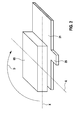
- FIG. 2 shows a state at the beginning of the preparation of the electrode coil 10 of the battery cell 2.
- a winding core 65 with the wound anode 21 is shown schematically, in perspective.
- the cathode 22 and the separator 18, which comprises two films are not shown in this illustration.
- the winding core 65 is rotated by a drive, not shown, about a winding axis A in a direction of rotation D.
- the direction of rotation D is clockwise.
- the winding core 65 is present prismatic, or cuboid, formed. With regard to the winding axis A, that is to say when looking at the winding core 65 in the direction of the winding axis A, the winding core 65 has a rectangular cross-section.
- the rectangular cross-section of the winding core 65 comprises two mutually parallel long sides and two mutually parallel short sides.
- winding core 65 Parallel to the long sides of the rectangular cross section of the winding core 65 extends a longitudinal axis X of the winding core 65.
- the longitudinal axis X of the winding core 65 thereby cuts the winding axis A at right angles.
- the winding core 65 is thus formed symmetrically symmetrical to a plane which is spanned by the longitudinal axis X and the winding axis A.
- winding core 65 with respect to the winding axis A
- the cross section of the winding core 65 should be designed to be elongated in the direction of the longitudinal axis X.
- the winding core 65 may have a diamond-shaped, oval or polygonal cross-section.
- the winding core 65 has no rotational symmetry with respect to the winding axis A.
- Both films of the separator 18, not shown, are placed on the winding core 65 and secured to the winding core 65.
- a rotation of the winding core 65 about the winding axis A a few layers of the films are first wound onto the winding core 65.
- a portion of the cathode 22, not shown here, is applied flat to the other film of the separator 18, which abuts against a surface of the winding core 65.
- This film is thus arranged between the cathode 22 and the surface of the winding core 65.
- This surface extends parallel to the plane spanned by the longitudinal axis X and the winding axis A.
- a cathode contact lug 26, not shown here, of the current collector 32 of the cathode 22 projects away from the cathode 22 and extends parallel to the winding axis A.
- the anode contact lug 25 of the anode 21 lies diametrically opposite the cathode contact lug 26, not shown here, of the cathode 22 with respect to the winding axis A.
- the anode 21, the cathode 22 and the two films of the separator 18 are wound by a rotation of the winding core 65 about the winding axis A in the direction of rotation D on the winding core 65.
- FIG. 3 shows a schematic plan view of the electrode coil 10 in the manufacturing process during the winding of the anode 21 and the cathode 22 on the winding core 65. Between the anode 21 and the cathode 22 in each case a film of the separator 18, not shown here is arranged.
- the inner cathode contact tab 26 is also located near the winding core 65. With each subsequent position of the cathode 22, a further cathode contact lug 26 is placed on the respective preceding cathode contact lug 26. All cathode contact lugs 26 of the cathode 22 are arranged in alignment with each other in a cathode line 36.
- the anode line 35 and the cathode line 36 are parallel to each other.
- the anode line 35 and the cathode line 36 each intersect the longitudinal axis X, in the present case at right angles.
- the anode line 35 and the cathode line 36 each extend at a distance from the winding axis A, in this case at the same distance from the winding axis A, but diametrically opposite the winding axis A.
- the cathode contact lugs 26 and the anode contact lugs 25 are aligned relative to the winding core 65 such that during rotation about the winding axis A in the direction of rotation D of the winding core 65 0 moves the cathode contact lugs 26 and the anode contact lugs 25.
- the already wound cathode contact lugs 26 and the already wound anode contact lugs 25 hurry in the rotation about the winding axis A in the direction of rotation D so the winding core 65 before.
- the orientation of the cathode contact lugs 26 and the anode contact lugs 25 relative to the winding core 65 is dependent on the direction of rotation D.
- the direction of rotation D is clockwise.
- the anode contact lugs 25 are thus located to the right of the longitudinal axis X.
- the cathode contact lugs 26 are right of the longitudinal axis X.
- the anode contact lugs 25 and the cathode contact lugs 26 each have an inertial force F.
- the inertial forces F act at least approximately tangential to the direction of rotation D and the direction of rotation D opposite.
- the inertial forces F thus act from the anode contact lugs 25 and the cathode contact lugs 26 in the direction of the longitudinal axis X.
- the inertial forces F act at least approximately in the direction of the anode line 35 and the cathode line 36.
- the direction of rotation D is clockwise.
- the inertial forces F thus act in each case to the left, ie in the direction of the longitudinal axis X.
- the inertial forces F are already wound Cathode contact lugs 26 and the already wound anode contact lugs 25 each bent in the direction of the longitudinal axis X.
- cathode contact lugs 26 and on the already wound anode contact lugs 25 also acts due to the rotation of a centrifugal force, which is directed from the winding axis A in the radial direction to the outside.
- the cathode contact lugs 26 are not bendable relative to the rest of the cathode 22 in the radial direction.
- the anode contact lugs 25 are not bendable relative to the remaining anode 21 in the radial direction. The acting centrifugal forces thus have no significant influence on the cathode contact lugs 26 and on the anode contact lugs 25th
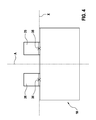
- FIG. 4 a schematic side view of the finished electrode coil 10 is shown.
- the winding core 65 remains in the electrode coil 10 but is concealed in the illustration shown.
- the winding core 65 can also be removed after winding up the anode 21, the cathode 22 and the two films of the separator 18.
- the anode contact lugs 25 of the anode 21 are arranged in alignment with each other in the anode line 35, and the cathode contact lugs 26 of the cathode 22 are arranged in alignment with each other in the cathode line 36.
- the anode contact lugs 25 and the cathode contact lugs 26 are each connected to a collector, and the collectors are electrically connected to the terminals 11, 12 of the battery cell 2.
Abstract
Description
- Die Erfindung betrifft ein Verfahren zur Herstellung eines Elektrodenwickels für eine Batteriezelle, wobei eine folienartig ausgebildete Kathode und eine folienartig ausgebildete Anode an einen Wickelkern angelegt werden, und die Kathode und die Anode durch Drehung des Wickelkerns um eine Wickelachse auf den Wickelkern aufgewickelt werden. Die Erfindung betrifft auch einen durch das erfindungsgemäße Verfahren hergestellten Elektrodenwickel sowie eine Batteriezelle.
- Elektrische Energie ist mittels Batterien speicherbar. Batterien wandeln chemische Reaktionsenergie in elektrische Energie um. Hierbei werden Primärbatterien und Sekundärbatterien unterschieden. Primärbatterien sind nur einmal funktionsfähig, während Sekundärbatterien, die auch als Akkumulator bezeichnet werden, wieder aufladbar sind. Eine Batterie umfasst dabei eine oder mehrere Batteriezellen.
- In einem Akkumulator finden insbesondere sogenannte Lithium-Ionen-Batteriezellen Verwendung. Diese zeichnen sich unter anderem durch hohe Energiedichten, thermische Stabilität und eine äußerst geringe Selbstentladung aus. Lithium-Ionen-Batteriezellen kommen unter anderem in Kraftfahrzeugen, insbesondere in Elektrofahrzeugen (Electric Vehicle, EV), Hybridfahrzeugen (Hybride Electric Vehicle, HEV) sowie Plug-In-Hybridfahrzeugen (Plug-In-Hybride Electric Vehicle, PHEV) zum Einsatz.
- Lithium-Ionen-Batteriezellen weisen eine positive Elektrode, die auch als Kathode bezeichnet wird, und eine negative Elektrode, die auch als Anode bezeichnet wird, auf. Die Kathode sowie die Anode umfassen je einen Stromableiter, auf den ein Aktivmaterial aufgebracht ist. Bei dem Aktivmaterial für die Kathode handelt es sich beispielsweise um ein Metalloxid. Bei dem Aktivmaterial für die Anode handelt es sich beispielsweise um Silizium. Aber auch Graphit ist als Aktivmaterial für Anoden verbreitet.
- Die Elektroden der Batteriezelle sind folienartig ausgebildet und unter Zwischenlage eines Separators, welcher die Anode von der Kathode trennt, zu einem Elektrodenwickel gewunden. Ein solcher Elektrodenwickel wird auch als Jelly-Roll bezeichnet. Die beiden Elektroden des Elektrodenwickels werden mittels Kollektoren elektrisch mit Polen der Batteriezelle, welche auch als Terminals bezeichnet werden, verbunden. Die Elektroden und der Separator sind von einem in der Regel flüssigen Elektrolyt umgeben.
- Eine gattungsgemäße Batteriezelle, die eine Anode und eine Kathode umfasst, ist beispielsweise aus der
DE 10 2012 223 796 A1 bekannt. - Ein Verfahren zur Herstellung eines Elektrodenwickels für eine Batteriezelle geht aus der
KR20120019217 A - Auch aus der
US 2014/0186671 A1 ist ein Verfahren zur Herstellung eines Elektrodenwickels für eine Batteriezelle bekannt. Dabei werden eine Anode und eine Kathode unter Zwischenlage eines Separators auf einen Wickelkern aufgewickelt. - Es wird ein Verfahren zur Herstellung eines Elektrodenwickels für eine Batteriezelle vorgeschlagen, wobei eine folienartig ausgebildete Kathode und eine folienartig ausgebildete Anode an einen Wickelkern angelegt werden, und die Kathode und die Anode durch Drehung des Wickelkerns um eine Wickelachse auf den Wickelkern aufgewickelt werden, wobei die Kathode sich parallel zu der Wickelachse erstreckende Kathodenkontaktfahnen aufweist und/oder wobei die Anode sich parallel zu der Wickelachse erstreckende Anodenkontaktfahnen aufweist.
- Erfindungsgemäß werden die Kathodenkontaktfahnen sowie die Anodenkontaktfahnen derart relativ zu dem Wickelkern ausgerichtet, dass die Kathodenkontaktfahnen sowie die Anodenkontaktfahnen durch Trägheitskräfte, die während der Drehung auf die Kathodenkontaktfahnen sowie auf die Anodenkontaktfahnen wirken, in Richtung auf eine Längsachse des Wickelkerns gebogen werden, wobei die Längsachse die Wickelachse rechtwinklig schneidet.
- Der Wickelkern weist dabei, bezüglich der Wickelachse, einen von einer rotationssymmetrischen Form abweichenden Querschnitt auf. Insbesondere weist der Wickelkern keinen kreisrunden Querschnitt auf. Der Wickelkern ist also nicht kreiszylindrisch ausgestaltet.
- Vorzugsweise weist der Wickelkern einen zumindest annähernd rechteckförmigen Querschnitt auf. Insbesondere weist der Wickelkern dabei keinen quadratischen Querschnitt auf. Die Längsachse erstreckt sich dabei parallel zu den langen Seiten des annähernd rechteckförmigen Querschnitts, also rechtwinklig zu den kurzen Seiten des annähernd rechteckförmigen Querschnitts.
- Vorteilhaft ist der Wickelkern ebenensymmetrisch zu einer durch die Wickelachse und die Längsachse aufgespannten Ebene ausgebildet. Insbesondere kann der Wickelkern prismatisch oder quaderförmig ausgestaltet sein.
- Die Kathodenkontaktfahnen sowie die Anodenkontaktfahnen werden dabei derart relativ zu dem Wickelkern ausgerichtet, dass während der Drehung der Wickelkern in Richtung auf die Kathodenkontaktfahnen sowie auf die Anodenkontaktfahnen bewegt wird. Die Kathodenkontaktfahnen sowie die Anodenkontaktfahnen eilen bei der Drehung um die Wickelachse somit dem Wickelkern vor.
- Vorzugsweise werden die Kathodenkontaktfahnen in einer Kathodenlinie fluchtend angeordnet, welche die Längsachse schneidet. Ebenso werden die Anodenkontaktfahnen vorzugsweise fluchtend in einer Anodenlinie angeordnet, welche die Längsachse schneidet.
- Dabei schneiden die Kathodenlinie sowie die Anodenlinie die Längsachse vorzugsweise rechtwinklig.
- Die Kathodenlinie, in der die Kathodenkontaktfahnen fluchtend angeordnet werden, verläuft vorzugsweise beabstandet zu der Wickelachse. Auch die Anodenlinie, in der die Anodenkontaktfahnen fluchtend angeordnet werden, verläuft vorzugsweise beabstandet zu der Wickelachse.
- Es wird auch ein Elektrodenwickel vorgeschlagen, der durch das erfindungsgemäße Verfahren hergestellt wird.
- Ebenso wird eine Batteriezelle vorgeschlagen, die mindestens einen erfindungsgemäßen Elektrodenwickel umfasst.
- Eine erfindungsgemäße Batteriezelle findet vorteilhaft Verwendung in einem Elektrofahrzeug (EV), in einem Hybridfahrzeug (HEV), in einem Plug-In-Hybridfahrzeug (PHEV), in einer stationären Batterie, insbesondere zur Netzstabilisierung in Haushalten, in einer Batterie in einer marinen Anwendung, beispielsweise beim Schiffsbau oder in Jet-Skis, oder in einer Batterie in einer aeronautischen Anwendung, insbesondere beim Flugzeugbau.
- Durch die Drehung des Wickelkerns in eine Drehrichtung erfahren die Kathodenkontaktfahnen sowie die Anodenkontaktfahnen aufgrund ihrer Massenträgheit eine Biegung. Bei einer ungünstigen Ausrichtung der Kathodenkontaktfahnen sowie der Anodenkontaktfahnen erfolgt besagte Biegung in Radialrichtung nach außen, also von der Wickelachse weg. Dabei kann eine Kathodenkontaktfahne oder eine Anodenkontaktfahne um 180° umgebogen werden und wird dann bei der nächsten Umdrehung des Wickelkerns von der folgenden Lage der Anode oder der Kathode überdeckt und so in den Elektrodenwickel eingewickelt.
- Beim dem erfindungsgemäßen Verfahren zur Herstellung eines Elektrodenwickels ist eine Biegung der Kathodenkontaktfahnen sowie der Anodenkontaktfahnen in Radialrichtung nach außen, also von der Wickelachse weg, ausgeschlossen. Ein Einwickeln von Kathodenkontaktfahnen sowie von Anodenkontaktfahnen in den Elektrodenwickel ist somit verhindert. Dadurch sinkt die Ausschussrate, und die Effektivität bei der Herstellung von Elektrodenwickeln ist erhöht.
- Ausführungsformen der Erfindung werden anhand der Zeichnungen und der nachfolgenden Beschreibung näher erläutert.
- Es zeigen:
- Figur 1
- eine schematische Darstellung einer Batteriezelle,
- Figur 2
- eine schematische, perspektivische Darstellung eines Wickelkerns mit einer aufzuwickelnden Anode,
- Figur 3
- eine schematische Draufsicht auf einen Elektrodenwickel während des Aufwickelns einer Anode und einer Kathode auf einen Wickelkern und
- Figur 4
- eine schematische Seitenansicht eines fertig gestellten Elektrodenwickels.
- In der nachfolgenden Beschreibung der Ausführungsformen der Erfindung werden gleiche oder ähnliche Elemente mit gleichen Bezugszeichen bezeichnet, wobei auf eine wiederholte Beschreibung dieser Elemente in Einzelfällen verzichtet wird. Die Figuren stellen den Gegenstand der Erfindung nur schematisch dar.
- In
Figur 1 ist eine Batteriezelle 2 schematisch dargestellt. Die Batteriezelle 2 umfasst ein Zellengehäuse 3, welches prismatisch, vorliegend quaderförmig, ausgebildet ist. Das Zellengehäuse 3 ist vorliegend elektrisch leitend ausgeführt und beispielsweise aus Aluminium gefertigt. Das Zellengehäuse 3 kann aber auch aus einem elektrisch isolierenden Material, beispielsweise Kunststoff, gefertigt sein. - Die Batteriezelle 2 umfasst ein negatives Terminal 11 und ein positives Terminal 12. Über die Terminals 11, 12 kann eine von der Batteriezelle 2 zur Verfügung gestellte Spannung abgegriffen werden. Ferner kann die Batteriezelle 2 über die Terminals 11, 12 auch geladen werden. Die Terminals 11, 12 sind beabstandet voneinander an einer Deckfläche des prismatischen Zellengehäuses 3 angeordnet.
- Innerhalb des Zellengehäuses 3 der Batteriezelle 2 ist ein Elektrodenwickel 10 angeordnet, welcher zwei Elektroden, nämlich eine Anode 21 und eine Kathode 22, aufweist. Die Anode 21 und die Kathode 22 sind jeweils folienartig ausgeführt und unter Zwischenlage eines Separators 18 zu dem Elektrodenwickel 10 gewickelt. Es ist auch denkbar, dass mehrere Elektrodenwickel 10 in dem Zellengehäuse 3 vorgesehen sind.
- Die Anode 21 umfasst ein anodisches Aktivmaterial 41, welches folienartig ausgeführt ist. Das anodische Aktivmaterial 41 weist als Grundstoff vorliegend Silizium oder eine Silizium enthaltende Legierung auf. Die Anode 21 umfasst ferner einen Stromableiter 31, welcher ebenfalls folienartig ausgebildet ist. Das anodische Aktivmaterial 41 und der Stromableiter 31 der Anode 21 sind flächig aneinander gelegt und miteinander verbunden. Somit ist auch die Anode 21 folienartig ausgebildet.
- Der Stromableiter 31 der Anode 21 ist elektrisch leitfähig ausgeführt und aus einem Metall gefertigt, beispielsweise aus Kupfer. Von dem Stromableiter 31 der Anode 21 ragen Anodenkontaktfahnen 25 weg. Die Anodenkontaktfahnen 25 des Stromableiters 31 der Anode 21 sind elektrisch mit dem negativen Terminal 11 der Batteriezelle 2 verbunden.
- Die Kathode 22 umfasst ein kathodisches Aktivmaterial 42, welches folienartig ausgeführt ist. Das kathodische Aktivmaterial 42 weist als Grundstoff ein Metalloxid auf, beispielsweise Lithium-Kobalt-Oxid (LiCoO2). Die Kathode 22 umfasst ferner einen Stromableiter 32, welcher ebenfalls folienartig ausgebildet ist. Das kathodische Aktivmaterial 42 und der Stromableiter 32 der Kathode 22 sind flächig aneinander gelegt und miteinander verbunden. Somit ist auch die Kathode 22 folienartig ausgebildet.
- Der Stromableiter 32 der Kathode 22 ist elektrisch leitfähig ausgeführt und aus einem Metall gefertigt, beispielsweise aus Aluminium. Von dem Stromableiter 32 der Kathode 22 ragen Kathodenkontaktfahnen 26 weg. Die Kathodenkontaktfahnen 26 des Stromableiters 32 der Kathode 22 sind elektrisch mit dem positiven Terminal 12 der Batteriezelle 2 verbunden.
- Die Anode 21 und die Kathode 22 sind durch den Separator 18 voneinander getrennt. Der Separator 18 ist ebenfalls folienartig ausgebildet. Der Separator 18 ist elektrisch isolierend ausgebildet, aber ionisch leitfähig, also für Lithiumionen durchlässig.
- Das Zellengehäuse 3 der Batteriezelle 2 ist mit einem flüssigen Elektrolyt 15, oder mit einem Polymerelektrolyt, gefüllt. Der Elektrolyt 15 umgibt dabei die Anode 21, die Kathode 22 und den Separator 18. Auch der Elektrolyt 15 ist ionisch leitfähig.
- In
Figur 2 zeigt einen Zustand bei Beginn der Herstellung des Elektrodenwickels 10 der Batteriezelle 2. Dabei ist ein Wickelkern 65 mit der aufzuwickelnden Anode 21 schematisch, perspektivisch dargestellt. Die Kathode 22 sowie der Separator 18, welcher zwei Folien umfasst, sind in dieser Darstellung nicht gezeigt. Während der Herstellung des Elektrodenwickels 10 wird der Wickelkern 65 durch einen nicht dargestellten Antrieb um eine Wickelachse A in eine Drehrichtung D gedreht. In der gezeigten Darstellung verläuft die Drehrichtung D im Uhrzeigersinn. - Der Wickelkern 65 ist vorliegend prismatisch, beziehungsweise quaderförmig, ausgebildet. Bezüglich der Wickelachse A, also bei Blick auf den Wickelkern 65 in Richtung der Wickelachse A, weist der Wickelkern 65 einen rechteckförmigen Querschnitt auf. Der rechteckförmige Querschnitt des Wickelkerns 65 umfasst zwei parallel zueinander verlaufende lange Seiten sowie zwei parallel zueinander verlaufende kurze Seiten.
- Parallel zu den langen Seiten des rechteckförmigen Querschnitts des Wickelkerns 65 erstreckt sich eine Längsachse X des Wickelkerns 65. Die Längsachse X des Wickelkerns 65 schneidet dabei die Wickelachse A rechtwinklig. Der Wickelkern 65 ist somit ebenensymmetrisch zu einer Ebene ausgebildet, welche durch die Längsachse X und die Wickelachse A aufgespannt wird.
- Auch andere Querschnitte des Wickelkerns 65 bezüglich der Wickelachse A sind denkbar. Der Querschnitt des Wickelkerns 65 soll dabei länglich in Richtung der Längsachse X ausgestaltet sein. Beispielsweise kann der Wickelkern 65 einen rautenförmigen, ovalen oder polygonalen Querschnitt haben. Insbesondere weist der Wickelkern 65 jedoch keine Rotationssymmetrie bezüglich der Wickelachse A auf.
- Beide Folien des nicht dargestellten Separators 18 werden auf den Wickelkern 65 aufgelegt und an dem Wickelkern 65 befestigt. Durch eine Drehung des Wickelkerns 65 um die Wickelachse A werden zunächst einige Lagen der Folien auf den Wickelkern 65 aufgewickelt.
- Dann wird ein Teil der Anode 21 flächig an die eine Folie des Separators 18 angelegt, die an einer Oberfläche des Wickelkerns 65 anliegt. Diese Folie ist somit zwischen der Anode 21 und der Oberfläche des Wickelkerns 65 angeordnet. Diese Oberfläche erstreckt sich parallel zu der durch die Längsachse X und die Wickelachse A aufgespannten Ebene. Eine Anodenkontaktfahne 25 des Stromableiters 31 der Anode 21 ragt von der Anode 21 weg und erstreckt sich parallel zu der Wickelachse A.
- In einem folgenden Schritt wird auch ein Teil der hier nicht dargestellten Kathode 22 flächig an die andere Folie des Separators 18 angelegt, die an einer Oberfläche des Wickelkerns 65 anliegt. Diese Folie ist somit zwischen der Kathode 22 und der Oberfläche des Wickelkerns 65 angeordnet. Diese Oberfläche erstreckt sich parallel zu der durch die Längsachse X und die Wickelachse A aufgespannten Ebene. Eine hier nicht dargestellte Kathodenkontaktfahne 26 des Stromableiters 32 der Kathode 22 ragt von der Kathode 22 weg und erstreckt sich parallel zu der Wickelachse A.
- Die Anodenkontaktfahne 25 der Anode 21 liegt dabei der hier nicht dargestellten Kathodenkontaktfahne 26 der Kathode 22 diametral in Bezug auf die Wickelachse A gegenüber.
- Anschließend werden die Anode 21, die Kathode 22 sowie die beiden Folien des Separators 18 durch eine Drehung des Wickelkerns 65 um die Wickelachse A in die Drehrichtung D auf den Wickelkern 65 aufgewickelt.
-
Figur 3 zeigt eine schematische Draufsicht auf den Elektrodenwickel 10 im Herstellprozess während des Aufwickelns der Anode 21 und der Kathode 22 auf den Wickelkern 65. Zwischen der Anode 21 und der Kathode 22 ist jeweils eine Folie des hier nicht dargestellten Separators 18 angeordnet. - Die innere Anodenkontaktfahne 25, die auch in
Figur 3 gezeigt ist, ist dem Wickelkern 65 nahe gelegen. Mit jeder folgenden Lage der Anode 21 wird eine weitere Anodenkontaktfahne 25 auf die jeweils vorhergehende Anodenkontaktfahne 25 gelegt. Alle Anodenkontaktfahnen 25 der Anode 21 sind dabei miteinander fluchtend in einer Anodenlinie 35 angeordnet. - Die innere Kathodenkontaktfahne 26 ist ebenfalls dem Wickelkern 65 nahe gelegen. Mit jeder folgenden Lage der Kathode 22 wird eine weitere Kathodenkontaktfahne 26 auf die jeweils vorhergehende Kathodenkontaktfahne 26 gelegt. Alle Kathodenkontaktfahnen 26 der Kathode 22 sind dabei miteinander fluchtend in einer Kathodenlinie 36 angeordnet.
- Die Anodenlinie 35 und die Kathodenlinie 36 verlaufen parallel zueinander. Die Anodenlinie 35 und die Kathodenlinie 36 schneiden jeweils die Längsachse X, vorliegend rechtwinklig. Die Anodenlinie 35 und die Kathodenlinie 36 verlaufen jeweils beabstandet von der Wickelachse A, vorliegend im gleichen Abstand zu der Wickelachse A, aber diametral der Wickelachse A gegenüber liegend.
- Die Kathodenkontaktfahnen 26 sowie die Anodenkontaktfahnen 25 werden dabei derart relativ zu dem Wickelkern 65 ausgerichtet, dass während der Drehung um die Wickelachse A in die Drehrichtung D der Wickelkern 65 0 die Kathodenkontaktfahnen 26 sowie auf die Anodenkontaktfahnen 25 bewegt. Die bereits aufgewickelten Kathodenkontaktfahnen 26 sowie die bereits aufgewickelten Anodenkontaktfahnen 25 eilen bei der Drehung um die Wickelachse A in die Drehrichtung D also dem Wickelkern 65 vor.
- Die Ausrichtung der Kathodenkontaktfahnen 26 sowie der Anodenkontaktfahnen 25 relativ zu dem Wickelkern 65 ist von der Drehrichtung D abhängig. In der vorliegenden Ausführungsform verläuft die Drehrichtung D im Uhrzeigersinn. Bei Blick von der Wickelachse A in Richtung der Längsachse X liegen die Anodenkontaktfahnen 25 somit rechts von der Längsachse X. Ebenso liegen bei Blick von der Wickelachse A in Richtung der Längsachse X die Kathodenkontaktfahnen 26 rechts von der Längsachse X.
- Während der Drehung um die Wickelachse A in die Drehrichtung D wirkt auf die Anodenkontaktfahnen 25 sowie auf die Kathodenkontaktfahnen 26 jeweils eine Trägheitskraft F. Die Trägheitskräfte F wirken dabei zumindest annähernd tangential zu der Drehrichtung D und der Drehrichtung D entgegengesetzt. Die Trägheitskräfte F wirken also von den Anodenkontaktfahnen 25 und den Kathodenkontaktfahnen 26 in Richtung auf die Längsachse X. Die Trägheitskräfte F wirken zumindest annähernd in Richtung der Anodenlinie 35 sowie der Kathodenlinie 36.
- In der vorliegenden Ausführungsform verläuft die Drehrichtung D im Uhrzeigersinn. Bei Blick von der Wickelachse A in Richtung der Längsachse X wirken die Trägheitskräfte F somit jeweils nach links, also in Richtung auf die Längsachse X. Durch die Trägheitskräfte F werden die bereits aufgewickelten Kathodenkontaktfahnen 26 sowie die bereits aufgewickelten Anodenkontaktfahnen 25 jeweils in Richtung auf die Längsachse X gebogen.
- Auf die bereits aufgewickelten Kathodenkontaktfahnen 26 sowie auf die bereits aufgewickelten Anodenkontaktfahnen 25 wirkt aufgrund der Drehung auch eine Fliehkraft, die von der Wickelachse A in Radialrichtung nach außen gerichtet ist. Die Kathodenkontaktfahnen 26 sind jedoch in Radialrichtung nicht relativ zu der übrigen Kathode 22 biegbar. Ebenso sind die Anodenkontaktfahnen 25 in Radialrichtung nicht relativ zu der übrigen Anode 21 biegbar. Die wirkenden Fliehkräfte haben somit keinen wesentlichen Einfluss auf die Kathodenkontaktfahnen 26 und auf die Anodenkontaktfahnen 25.
- In
Figur 4 ist eine schematische Seitenansicht des fertig gestellten Elektrodenwickels 10 gezeigt. In der vorliegenden Ausführungsform verbleibt der Wickelkern 65 in dem Elektrodenwickel 10, ist aber in der gezeigten Darstellung verdeckt. Der Wickelkern 65 kann auch nach Aufwickeln der Anode 21, der Kathode 22 und der beiden Folien des Separators 18 entnommen werden. - Die Anodenkontaktfahnen 25 der Anode 21 sind miteinander fluchtend in der Anodenlinie 35 angeordnet, und die Kathodenkontaktfahnen 26 der Kathode 22 sind miteinander fluchtend in der Kathodenlinie 36 angeordnet. In einem nachfolgenden Schritt werden die Anodenkontaktfahnen 25 sowie die Kathodenkontaktfahnen 26 jeweils mit einem Kollektor verbunden, und die Kollektoren werden elektrisch mit den Terminals 11, 12 der Batteriezelle 2 verbunden.
- Die Erfindung ist nicht auf die hier beschriebenen Ausführungsbeispiele und die darin hervorgehobenen Aspekte beschränkt. Vielmehr ist innerhalb des durch die Ansprüche angegebenen Bereichs eine Vielzahl von Abwandlungen möglich, die im Rahmen fachmännischen Handelns liegen.
Claims (11)
- Verfahren zur Herstellung eines Elektrodenwickels (10) für eine Batteriezelle (2), wobei
eine folienartig ausgebildete Kathode (22) und eine folienartig ausgebildete Anode (21) an einen Wickelkern (65) angelegt werden, und die Kathode (22) und die Anode (21) durch Drehung des Wickelkerns (65) um eine Wickelachse (A) auf den Wickelkern (65) aufgewickelt werden, wobei
die Kathode (22) sich parallel zu der Wickelachse (A) erstreckende Kathodenkontaktfahnen (26) aufweist und/oder die Anode (21) sich parallel zu der Wickelachse (A) erstreckende Anodenkontaktfahnen (25) aufweist,
dadurch gekennzeichnet, dass
die Kathodenkontaktfahnen (26) und/oder die Anodenkontaktfahnen (25) derart relativ zu dem Wickelkern (65) ausgerichtet werden, dass die Kathodenkontaktfahnen (26) und/oder die Anodenkontaktfahnen (25) durch während der Drehung wirkende Trägheitskräfte (F) in Richtung auf eine die Wickelachse (A) rechtwinklig schneidende Längsachse (X) des Wickelkerns (65) gebogen werden. - Verfahren nach Anspruch 1, dadurch gekennzeichnet, dass der Wickelkern (65) bezüglich der Wickelachse (A) einen von einer rotationssymmetrischen Form abweichenden Querschnitt aufweist.
- Verfahren nach Anspruch 2, dadurch gekennzeichnet, dass der Wickelkern (65) einen zumindest annähernd rechteckförmigen Querschnitt aufweist, wobei sich die Längsachse (X) parallel zu den langen Seiten des annähernd rechteckförmigen Querschnitts erstreckt.
- Verfahren nach einem der vorstehenden Ansprüche, dadurch gekennzeichnet, dass
der Wickelkern (65) ebenensymmetrisch zu einer durch die Wickelachse (A) und die Längsachse (X) aufgespannten Ebene ausgebildet ist. - Verfahren nach einem der vorstehenden Ansprüche, dadurch gekennzeichnet, dass
die Kathodenkontaktfahnen (26) und/oder die Anodenkontaktfahnen (25) derart relativ zu dem Wickelkern (65) ausgerichtet werden, dass während der Drehung der Wickelkern (65) in Richtung auf die Kathodenkontaktfahnen (26) und/oder auf die Anodenkontaktfahnen (25) bewegt wird. - Verfahren nach einem der vorstehenden Ansprüche, dadurch gekennzeichnet, dass
die Kathodenkontaktfahnen (26) in einer Kathodenlinie (36) angeordnet werden, welche die Längsachse (X) schneidet, und/oder dass die Anodenkontaktfahnen (25) in einer Anodenlinie (35) angeordnet werden, welche die Längsachse (X) schneidet. - Verfahren nach Anspruch 6, dadurch gekennzeichnet, dass die Kathodenlinie (36) und/oder die Anodenlinie (35) die Längsachse (X) rechtwinklig schneidet.
- Verfahren nach einem der vorstehenden Ansprüche, dadurch gekennzeichnet, dass
die Kathodenkontaktfahnen (26) in einer Kathodenlinie (36) angeordnet werden, welche beabstandet zu der Wickelachse (A) verläuft, und/oder dass
die Anodenkontaktfahnen (25) in einer Anodenlinie (35) angeordnet werden, welche beabstandet zu der Wickelachse (A) verläuft. - Elektrodenwickel (10), hergestellt durch ein Verfahren nach einem der vorstehenden Ansprüche.
- Batteriezelle (2), umfassend mindestens einen Elektrodenwickel (10) nach Anspruch 9.
- Verwendung einer Batteriezelle (2) nach Anspruch 10 in einem Elektrofahrzeug (EV), in einem Hybridfahrzeug (HEV), in einem Plug-In-Hybridfahrzeug (PHEV), in einer stationären Batterie, in einer Batterie in einer marinen Anwendung oder in einer Batterie in einer aeronautischen Anwendung.
Priority Applications (1)
| Application Number | Priority Date | Filing Date | Title |
|---|---|---|---|
| EP15182511.4A EP3136494A1 (de) | 2015-08-26 | 2015-08-26 | Verfahren zur herstellung eines elektrodenwickels, elektrodenwickel und batteriezelle |
Applications Claiming Priority (1)
| Application Number | Priority Date | Filing Date | Title |
|---|---|---|---|
| EP15182511.4A EP3136494A1 (de) | 2015-08-26 | 2015-08-26 | Verfahren zur herstellung eines elektrodenwickels, elektrodenwickel und batteriezelle |
Publications (1)
| Publication Number | Publication Date |
|---|---|
| EP3136494A1 true EP3136494A1 (de) | 2017-03-01 |
Family
ID=54011606
Family Applications (1)
| Application Number | Title | Priority Date | Filing Date |
|---|---|---|---|
| EP15182511.4A Withdrawn EP3136494A1 (de) | 2015-08-26 | 2015-08-26 | Verfahren zur herstellung eines elektrodenwickels, elektrodenwickel und batteriezelle |
Country Status (1)
| Country | Link |
|---|---|
| EP (1) | EP3136494A1 (de) |
Citations (6)
| Publication number | Priority date | Publication date | Assignee | Title |
|---|---|---|---|---|
| US20100081042A1 (en) * | 2008-09-30 | 2010-04-01 | Hideaki Morishima | Secondary battery |
| US20100124694A1 (en) * | 2008-11-14 | 2010-05-20 | Seiichi Hikata | Nonaqueous electrolyte battery, cutter and method of manufacturing electrode |
| JP2011146181A (ja) * | 2010-01-13 | 2011-07-28 | Hitachi Vehicle Energy Ltd | 扁平捲回式二次電池 |
| KR20120019217A (ko) | 2010-08-25 | 2012-03-06 | 주식회사 엘지화학 | 신규한 구조의 전극조립체 |
| DE102012223796A1 (de) | 2012-12-19 | 2014-06-26 | Robert Bosch Gmbh | Anordnung zum Kontaktieren einer Elektrodenanordnung in einer Batteriezelle |
| US20140186671A1 (en) | 2008-11-27 | 2014-07-03 | Mplus Corp. | Secondary cell |
-
2015
- 2015-08-26 EP EP15182511.4A patent/EP3136494A1/de not_active Withdrawn
Patent Citations (6)
| Publication number | Priority date | Publication date | Assignee | Title |
|---|---|---|---|---|
| US20100081042A1 (en) * | 2008-09-30 | 2010-04-01 | Hideaki Morishima | Secondary battery |
| US20100124694A1 (en) * | 2008-11-14 | 2010-05-20 | Seiichi Hikata | Nonaqueous electrolyte battery, cutter and method of manufacturing electrode |
| US20140186671A1 (en) | 2008-11-27 | 2014-07-03 | Mplus Corp. | Secondary cell |
| JP2011146181A (ja) * | 2010-01-13 | 2011-07-28 | Hitachi Vehicle Energy Ltd | 扁平捲回式二次電池 |
| KR20120019217A (ko) | 2010-08-25 | 2012-03-06 | 주식회사 엘지화학 | 신규한 구조의 전극조립체 |
| DE102012223796A1 (de) | 2012-12-19 | 2014-06-26 | Robert Bosch Gmbh | Anordnung zum Kontaktieren einer Elektrodenanordnung in einer Batteriezelle |
Similar Documents
| Publication | Publication Date | Title |
|---|---|---|
| EP3520163B1 (de) | Verfahren zur herstellung einer elektrodeneinheit für eine batteriezelle und elektrodeneinheit | |
| WO2018059967A1 (de) | Verfahren zur herstellung eines elektrodenstapels für eine batteriezelle und batteriezelle | |
| DE102016203918A1 (de) | Verfahren zur Herstellung eines Elektrodenstapels, Elektrodenstapel und Batteriezelle | |
| EP3300141B1 (de) | Verfahren zur herstellung eines elektrodenstapels für eine batteriezelle und batteriezelle | |
| EP3646397A1 (de) | Batteriezelle | |
| DE102015218695A1 (de) | Batteriezelle | |
| DE102016221562A1 (de) | Batteriezelle und Verfahren zur Herstellung einer Batteriezelle | |
| DE102015204111A1 (de) | Batteriezelle, Zellverbinder und Batteriemodul | |
| EP3216073B1 (de) | Elektrode für eine batteriezelle und batteriezelle | |
| EP3096371A1 (de) | Batteriezelle | |
| DE102016221539A1 (de) | Batteriezelle | |
| WO2016050430A1 (de) | Elektrode für eine batteriezelle und batteriezelle | |
| WO2016184654A1 (de) | Verfahren zum betrieb einer aufladbaren batteriezelle und batteriesteuergerät | |
| EP3136494A1 (de) | Verfahren zur herstellung eines elektrodenwickels, elektrodenwickel und batteriezelle | |
| DE102018201288A1 (de) | Batteriezelle | |
| EP3157077B1 (de) | Batteriezelle | |
| DE102014222332A1 (de) | Schichtaufbau für ein galvanisches Element | |
| WO2016120129A1 (de) | Batteriezelle und batteriesystem | |
| DE102016203240A1 (de) | Verfahren zur Herstellung einer Elektrode, Elektrode und Batteriezelle | |
| DE102017219227A1 (de) | Verfahren und Vorrichtung zur Herstellung einer Elektrodeneinheit für eine Batteriezelle und Batteriezelle | |
| WO2018082878A1 (de) | Batteriezelle | |
| WO2022079169A1 (de) | Verfahren zur bereitstellung einer batteriezelle und verwendung einer solchen | |
| DE102015223174A1 (de) | Batteriezelle | |
| DE102020213364A1 (de) | Batteriezelle und Verwendung einer solchen | |
| DE102018221904A1 (de) | Elektrodeneinheit für eine Batteriezelle, Batteriezelle und Verfahren zur Herstellung einer Elektrodeneinheit |
Legal Events
| Date | Code | Title | Description |
|---|---|---|---|
| PUAI | Public reference made under article 153(3) epc to a published international application that has entered the european phase |
Free format text: ORIGINAL CODE: 0009012 |
|
| STAA | Information on the status of an ep patent application or granted ep patent |
Free format text: STATUS: THE APPLICATION HAS BEEN PUBLISHED |
|
| AK | Designated contracting states |
Kind code of ref document: A1 Designated state(s): AL AT BE BG CH CY CZ DE DK EE ES FI FR GB GR HR HU IE IS IT LI LT LU LV MC MK MT NL NO PL PT RO RS SE SI SK SM TR |
|
| AX | Request for extension of the european patent |
Extension state: BA ME |
|
| STAA | Information on the status of an ep patent application or granted ep patent |
Free format text: STATUS: REQUEST FOR EXAMINATION WAS MADE |
|
| 17P | Request for examination filed |
Effective date: 20170901 |
|
| RBV | Designated contracting states (corrected) |
Designated state(s): AL AT BE BG CH CY CZ DE DK EE ES FI FR GB GR HR HU IE IS IT LI LT LU LV MC MK MT NL NO PL PT RO RS SE SI SK SM TR |
|
| STAA | Information on the status of an ep patent application or granted ep patent |
Free format text: STATUS: EXAMINATION IS IN PROGRESS |
|
| 17Q | First examination report despatched |
Effective date: 20180219 |
|
| RAP1 | Party data changed (applicant data changed or rights of an application transferred) |
Owner name: LITHIUM ENERGY JAPAN |
|
| STAA | Information on the status of an ep patent application or granted ep patent |
Free format text: STATUS: THE APPLICATION IS DEEMED TO BE WITHDRAWN |
|
| 18D | Application deemed to be withdrawn |
Effective date: 20180703 |