EP3136073B1 - Device for measuring altitude and portable object including such a device - Google Patents
Device for measuring altitude and portable object including such a device Download PDFInfo
- Publication number
- EP3136073B1 EP3136073B1 EP16181795.2A EP16181795A EP3136073B1 EP 3136073 B1 EP3136073 B1 EP 3136073B1 EP 16181795 A EP16181795 A EP 16181795A EP 3136073 B1 EP3136073 B1 EP 3136073B1
- Authority
- EP
- European Patent Office
- Prior art keywords
- pressure sensor
- atmospheric pressure
- measurement device
- altitude measurement
- altitude
- Prior art date
- Legal status (The legal status is an assumption and is not a legal conclusion. Google has not performed a legal analysis and makes no representation as to the accuracy of the status listed.)
- Active
Links
- 230000005540 biological transmission Effects 0.000 claims description 39
- 238000005259 measurement Methods 0.000 claims description 31
- 230000033001 locomotion Effects 0.000 claims description 15
- 230000000694 effects Effects 0.000 claims description 5
- 241000669069 Chrysomphalus aonidum Species 0.000 claims description 4
- 230000007423 decrease Effects 0.000 claims description 2
- 230000004913 activation Effects 0.000 claims 3
- 230000009466 transformation Effects 0.000 claims 2
- 238000003780 insertion Methods 0.000 claims 1
- 230000037431 insertion Effects 0.000 claims 1
- 239000000523 sample Substances 0.000 description 12
- 239000002775 capsule Substances 0.000 description 6
- 239000012528 membrane Substances 0.000 description 6
- 239000004575 stone Substances 0.000 description 5
- 238000004519 manufacturing process Methods 0.000 description 4
- 238000007789 sealing Methods 0.000 description 2
- 238000004026 adhesive bonding Methods 0.000 description 1
- 230000000295 complement effect Effects 0.000 description 1
- 239000006185 dispersion Substances 0.000 description 1
- 230000005489 elastic deformation Effects 0.000 description 1
- 239000000463 material Substances 0.000 description 1
- 238000012986 modification Methods 0.000 description 1
- 230000004048 modification Effects 0.000 description 1
- 230000000717 retained effect Effects 0.000 description 1
- XLYOFNOQVPJJNP-UHFFFAOYSA-N water Substances O XLYOFNOQVPJJNP-UHFFFAOYSA-N 0.000 description 1
- 238000003466 welding Methods 0.000 description 1
Images


Classifications
-
- G—PHYSICS
- G01—MEASURING; TESTING
- G01C—MEASURING DISTANCES, LEVELS OR BEARINGS; SURVEYING; NAVIGATION; GYROSCOPIC INSTRUMENTS; PHOTOGRAMMETRY OR VIDEOGRAMMETRY
- G01C5/00—Measuring height; Measuring distances transverse to line of sight; Levelling between separated points; Surveyors' levels
- G01C5/06—Measuring height; Measuring distances transverse to line of sight; Levelling between separated points; Surveyors' levels by using barometric means
-
- G—PHYSICS
- G01—MEASURING; TESTING
- G01L—MEASURING FORCE, STRESS, TORQUE, WORK, MECHANICAL POWER, MECHANICAL EFFICIENCY, OR FLUID PRESSURE
- G01L27/00—Testing or calibrating of apparatus for measuring fluid pressure
- G01L27/002—Calibrating, i.e. establishing true relation between transducer output value and value to be measured, zeroing, linearising or span error determination
-
- G—PHYSICS
- G01—MEASURING; TESTING
- G01L—MEASURING FORCE, STRESS, TORQUE, WORK, MECHANICAL POWER, MECHANICAL EFFICIENCY, OR FLUID PRESSURE
- G01L7/00—Measuring the steady or quasi-steady pressure of a fluid or a fluent solid material by mechanical or fluid pressure-sensitive elements
- G01L7/02—Measuring the steady or quasi-steady pressure of a fluid or a fluent solid material by mechanical or fluid pressure-sensitive elements in the form of elastically-deformable gauges
- G01L7/10—Measuring the steady or quasi-steady pressure of a fluid or a fluent solid material by mechanical or fluid pressure-sensitive elements in the form of elastically-deformable gauges of the capsule type
- G01L7/104—Measuring the steady or quasi-steady pressure of a fluid or a fluent solid material by mechanical or fluid pressure-sensitive elements in the form of elastically-deformable gauges of the capsule type with mechanical transmitting or indicating means
-
- G—PHYSICS
- G01—MEASURING; TESTING
- G01L—MEASURING FORCE, STRESS, TORQUE, WORK, MECHANICAL POWER, MECHANICAL EFFICIENCY, OR FLUID PRESSURE
- G01L7/00—Measuring the steady or quasi-steady pressure of a fluid or a fluent solid material by mechanical or fluid pressure-sensitive elements
- G01L7/02—Measuring the steady or quasi-steady pressure of a fluid or a fluent solid material by mechanical or fluid pressure-sensitive elements in the form of elastically-deformable gauges
- G01L7/10—Measuring the steady or quasi-steady pressure of a fluid or a fluent solid material by mechanical or fluid pressure-sensitive elements in the form of elastically-deformable gauges of the capsule type
- G01L7/12—Measuring the steady or quasi-steady pressure of a fluid or a fluent solid material by mechanical or fluid pressure-sensitive elements in the form of elastically-deformable gauges of the capsule type with exhausted chamber; Aneroid barometers
- G01L7/14—Measuring the steady or quasi-steady pressure of a fluid or a fluent solid material by mechanical or fluid pressure-sensitive elements in the form of elastically-deformable gauges of the capsule type with exhausted chamber; Aneroid barometers with zero-setting means
-
- G—PHYSICS
- G04—HOROLOGY
- G04B—MECHANICALLY-DRIVEN CLOCKS OR WATCHES; MECHANICAL PARTS OF CLOCKS OR WATCHES IN GENERAL; TIME PIECES USING THE POSITION OF THE SUN, MOON OR STARS
- G04B47/00—Time-pieces combined with other articles which do not interfere with the running or the time-keeping of the time-piece
- G04B47/06—Time-pieces combined with other articles which do not interfere with the running or the time-keeping of the time-piece with attached measuring instruments, e.g. pedometer, barometer, thermometer or compass
- G04B47/066—Time-pieces combined with other articles which do not interfere with the running or the time-keeping of the time-piece with attached measuring instruments, e.g. pedometer, barometer, thermometer or compass with a pressure sensor
Landscapes
- Physics & Mathematics (AREA)
- General Physics & Mathematics (AREA)
- Engineering & Computer Science (AREA)
- Radar, Positioning & Navigation (AREA)
- Remote Sensing (AREA)
- Measuring Fluid Pressure (AREA)
- A Measuring Device Byusing Mechanical Method (AREA)
Description
La présente invention concerne un dispositif de mesure de l'altitude. Plus précisément, la présente invention concerne un dispositif de mesure de l'altitude comprenant un capteur de pression anéroïde. La présente invention concerne également un objet portable, par exemple une montre-bracelet, comprenant un dispositif de mesure de l'altitude selon l'invention.The present invention relates to a device for measuring altitude. More specifically, the present invention relates to an altitude measuring device comprising an aneroid pressure sensor. The present invention also relates to a portable object, for example a wristwatch, comprising an altitude measuring device according to the invention.
De nombreux dispositifs de mesure de l'altitude sont connus, parmi lesquels les altimètres de parachutisme dont l'élément sensible est un capteur de pression de type anéroïde. De tels altimètres comprennent typiquement un cadran dont le tour est gradué entre 0 et 4000 mètres d'altitude. Une analyse faite par la Demanderesse de plusieurs altimètres achetés dans le commerce fait ressortir une hystérèse. Ce défaut de linéarité a été mis en évidence par le calcul du travail des forces de frottement dans le mécanisme de ces altimètres. Le réglage du mécanisme a donc été effectué à la descente car l'erreur absolue de mesure de l'altitude est plus faible lorsque l'altitude diminue. Le réglage de ces altimètres a été effectué entre 0 et 3000 mètres d'altitude car il a été observé que l'erreur de mesure augmentait au-delà de 3000 mètres d'altitude. C'est ainsi que l'erreur maximale entre 0 et 3000 mètres d'altitude a atteint 21 mètres pour l'un des altimètres, et 34 mètres pour un autre altimètre. On voit donc que les altimètres de parachutisme qui ont été analysés présentent un défaut de linéarité qui conduit à une certaine imprécision de la mesure de l'ordre de 1%. En outre, étant donné la dispersion des caractéristiques des capsules anéroïdes et les tolérances de fabrication avec lesquelles sont conçus de tels altimètres, une opération préalable d'étalonnage est requise. Dans le cas des altimètres du type mentionné ci-dessus, cette opération d'étalonnage est assez fastidieuse. Elle est effectuée manuellement par une personne spécialement formée à cette tâche et consiste à lire la valeur affichée par l'altimètre successivement sous une pression équivalente à celle qui règne au niveau de la mer, puis par exemple sous une pression équivalente à 4000 mètres d'altitude, puis à nouveau sous une pression équivalente à 0 mètre et ainsi de suite. A chaque fois, le mécanisme est réglé pour que l'altitude affichée corresponde à la valeur de la pression ambiante. En procédant ainsi par itérations successives, on réduit progressivement l'erreur de mesure de l'altimètre.Numerous devices for measuring altitude are known, among which parachuting altimeters whose sensitive element is an aneroid type pressure sensor. Such altimeters typically include a dial whose turn is graduated between 0 and 4000 meters altitude. An analysis made by the Applicant of several altimeters purchased commercially highlights a hysteresis. This lack of linearity has been demonstrated by the calculation of the work of friction forces in the mechanism of these altimeters. The adjustment of the mechanism was thus made on the descent because the absolute error of measurement of the altitude is lower when the altitude decreases. The adjustment of these altimeters was carried out between 0 and 3000 meters of altitude because it was observed that the measurement error increased beyond 3000 meters of altitude. Thus the maximum error between 0 and 3000 meters of altitude reached 21 meters for one of the altimeters, and 34 meters for another altimeter. We therefore see that the parachuting altimeters that have been analyzed have a lack of linearity which leads to a certain inaccuracy of the measurement of the order of 1%. In addition, because of the dispersion of the characteristics of the aneroid capsules and the manufacturing tolerances with which such altimeters are designed, a prior calibration operation is required. In the case of altimeters of the type mentioned above, this calibration operation is rather tedious. It is performed manually by a person specially trained for this task and consists in reading the value displayed by the altimeter successively under a pressure equivalent to that which prevails at sea level, then for example under a pressure equivalent to 4000 meters. altitude, then again under a pressure equivalent to 0 meters and so on. Each time, the mechanism is set so that the displayed altitude corresponds to the value of the ambient pressure. By doing so by successive iterations, progressively reduces the measurement error of the altimeter.
Dans le document
Dans le document
Dans le document
Le document
Dans le document
Dans le document
Dans le document
La présente invention a pour but de remédier aux problèmes mentionnés ci-dessus ainsi qu'à d'autres encore en procurant un dispositif de mesure de l'altitude qui soit précis et dont l'hystérèse soit aussi réduite que possible.It is an object of the present invention to overcome the above-mentioned and other problems by providing an altitude measuring device which is accurate and whose hysteresis is as small as possible.
A cet effet, la présente invention concerne un dispositif de mesure de l'altitude selon la revendication 1. Grâce à ces caractéristiques, la présente invention procure un dispositif de mesure de l'altitude doté d'une très grande précision de mesure. Ce résultat remarquable est atteint grâce au fait que la précision de mesure du dispositif de mesure de l'altitude selon l'invention n'est pas affectée par les éventuelles variations dimensionnelles du capteur de pression atmosphérique. En effet, les tolérances de fabrication du capteur de pression atmosphérique sont intégralement compensées par le fait qu'il est possible d'ajuster avec précision la position du capteur de pression atmosphérique relativement aux autres composants du dispositif de mesure de l'altitude.For this purpose, the present invention relates to an altitude measuring device according to
Grâce à ces caractéristiques, la présente invention procure un dispositif de mesure de l'altitude dont les opérations d'étalonnage sont considérablement simplifiées et peuvent être automatisées si souhaité. Ce résultat remarquable est atteint grâce au fait que deux opérations de réglage effectuées pour l'une à une pression atmosphérique équivalent au niveau de la mer, et pour l'autre par exemple à une pression correspondant à 4000 mètres d'altitude, suffisent pour étalonner le dispositif de mesure de l'altitude selon l'invention. En outre, les opérations de réglage consistent simplement, pour les deux altitudes sélectionnées, à amener la ligne des points de contact entre la goupille de transmission et le râteau parallèle à l'axe de transmission, puis à ajuster la position du capteur de pression atmosphérique relativement aux autres composants du dispositif de mesure de l'altitude, ce qui peut être contrôlé visuellement très facilement même par un opérateur peu expérimenté, voire par une caméra. La précision avec laquelle il est possible d'effectuer l'étalonnage permet d'obtenir un dispositif de mesure de l'altitude présentant une hystérèse faible, voire nulle, ce qui permet à l'aiguille indicatrice de se déplacer de manière linéaire et donc d'effectuer, le cas échéant, plus d'un tour de cadran et ainsi de pouvoir mesurer avec précision des altitudes plus élevées.With these features, the present invention provides an altitude measuring device whose calibration operations are considerably simplified and can be automated if desired. This remarkable result is achieved thanks to the fact that two adjustment operations carried out for one at an atmospheric pressure equivalent to the sea level, and for the other for example at a pressure corresponding to 4000 meters altitude, are sufficient to calibrate the device for measuring the altitude according to the invention. In addition, the adjustment operations simply consist, for the two selected altitudes, in bringing the line of the points of contact between the transmission pin and the rake parallel to the transmission axis, and then in adjusting the position of the atmospheric pressure sensor. relative to the other components of the altitude measuring device, which can be visually controlled very easily even by an inexperienced operator, or even a camera. The precision with which calibration can be performed provides an altitude measurement device with low or no hysteresis, which allows the indicator needle to move linearly and thus perform, if necessary, more than one revolution of the dial and thus be able to accurately measure higher altitudes.
Selon une caractéristique complémentaire de l'invention, le support est doté sur sa périphérie extérieure d'un premier filetage qui coopère avec un second filetage prévu sur la périphérie intérieure du couvercle.According to a complementary feature of the invention, the support is provided on its outer periphery with a first thread which cooperates with a second thread provided on the inner periphery of the cover.
Selon une autre caractéristique de l'invention, le capteur de pression atmosphérique est un capteur anéroïde.According to another characteristic of the invention, the atmospheric pressure sensor is an aneroid sensor.
Selon encore une autre caractéristique de l'invention, le système d'actionnement comprend un palpeur qui est en appui sur le capteur de pression atmosphérique et qui est fixé rigidement sur un arbre de transmission agencé pour pivoter sous l'effet des mouvements de déformation du capteur de pression atmosphérique.According to yet another characteristic of the invention, the actuation system comprises a feeler which bears on the atmospheric pressure sensor and which is fixed rigidly on a transmission shaft arranged to pivot under the effect of the deformation movements of the atmospheric pressure sensor.
Selon encore une autre caractéristique de l'invention, l'arbre de transmission qui porte le palpeur s'étend selon une direction perpendiculaire à la direction rectiligne de déformation du capteur de pression atmosphérique.According to yet another characteristic of the invention, the transmission shaft which carries the probe extends in a direction perpendicular to the rectilinear direction of deformation of the atmospheric pressure sensor.
Selon encore une autre caractéristique de l'invention, une goupille de transmission fixée rigidement sur l'arbre de transmission communique au système d'actionnement les mouvements de déformation du capteur de pression atmosphérique.According to yet another characteristic of the invention, a transmission pin rigidly fixed to the transmission shaft communicates to the actuating system the deformation movements of the atmospheric pressure sensor.
Selon encore une autre caractéristique de l'invention, le système d'actionnement comprend un râteau pourvu d'un secteur denté en arc de cercle qui engrène avec un pignon solidaire d'un axe sur lequel est montée l'aiguille indicatrice.According to yet another characteristic of the invention, the actuating system comprises a rake provided with an arcuate tooth sector which meshes with a pinion integral with an axis on which the indicator needle is mounted.
Selon encore une autre caractéristique de l'invention, le dispositif de mesure de l'altitude comprend des moyens élastiques agencés pour maintenir le palpeur en appui sur le capteur de pression atmosphérique.According to yet another characteristic of the invention, the device for measuring the altitude comprises elastic means arranged to keep the probe bearing on the atmospheric pressure sensor.
Selon une première variante, les moyens élastiques comprennent un ressort hélicoïdal qui exerce une force élastique de rappel sur le râteau.According to a first variant, the elastic means comprise a helical spring which exerts an elastic return force on the rake.
Selon une seconde variante, les moyens élastiques comprennent un ressort en spires dont une courbe à l'intérieur est fixée sur l'axe sur lequel est montée l'aiguille indicatrice. Préférentiellement, un roulement à billes est disposé entre le ressort en spires et l'axe sur lequel est montée l'aiguille indicatrice.According to a second variant, the elastic means comprise a spring in turns, a curve inside of which is fixed on the axis on which the indicator needle is mounted. Preferably, a ball bearing is disposed between the spring in turns and the axis on which the indicator needle is mounted.
L'invention concerne également un objet portable tel qu'une montre-bracelet à l'intérieur duquel est logé le dispositif de mesure de l'altitude selon l'invention.The invention also relates to a portable object such as a wristwatch inside which is housed the altitude measuring device according to the invention.
D'autres caractéristiques et avantages de la présente invention ressortiront plus clairement de la description détaillée qui suit d'un mode de réalisation d'un dispositif de mesure de l'altitude selon l'invention, cet exemple étant donné à titre purement illustratif et non limitatif seulement, en liaison avec le dessin annexé sur lequel :
- la
figure 1 est une vue en perspective d'une boîte de montre-bracelet à l'intérieur de laquelle est logé un dispositif de mesure de l'altitude selon l'invention ; - la
figure 2 est une vue en perspective du dispositif de mesure de l'altitude selon l'invention ; - la
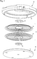
figure 3 est une vue en perspective et en éclaté d'un boîtier formé d'un couvercle et d'un support et à l'intérieur duquel est logé le dispositif de mesure de l'altitude selon l'invention ; - la
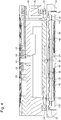
figure 4 est une vue en coupe selon l'axe midi-six heures de la boîte de montre-bracelet à l'intérieur de laquelle est logé le dispositif de mesure de l'altitude ; - la
figure 5 est une vue en perspective du dispositif de mesure de l'altitude selon l'invention contraint par un ressort hélicoïdal afin de maintenir le palpeur en contact permanent avec le capteur de pression atmosphérique ; - la
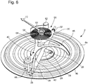
figure 6 est une vue en perspective du dispositif de mesure de l'altitude selon l'invention contraint par un ressort spiral afin de maintenir le palpeur en contact permanent avec le capteur de pression atmosphérique ; - la
figure 7 est une vue en perspective et en éclaté du boîtier de lafigure 3 à l'intérieur duquel est logé le capteur de pression atmosphérique ; - la
figure 8 est une vue en perspective et en éclaté de la cuve pour l'étalonnage du dispositif de mesure de l'altitude selon l'invention ; - la
figure 9 est une vue en perspective de la cuve à l'intérieur de laquelle est placé le dispositif de mesure de l'altitude selon l'invention pour son étalonnage ; - la
figure 10 est une vue en perspective et en éclaté du système d'entraînement permettant d'ajuster la hauteur du capteur de pression atmosphérique, et - la
figure 11 est une vue partielle en perspective du système d'immobilisation du dispositif de mesure de l'altitude selon l'invention à l'intérieur de la cuve étanche.
- the
figure 1 is a perspective view of a wristwatch box inside which is housed an altitude measuring device according to the invention; - the
figure 2 is a perspective view of the altitude measuring device according to the invention; - the
figure 3 is a perspective and exploded view of a housing formed of a cover and a support and inside which is housed the altitude measuring device according to the invention; - the
figure 4 is a sectional view along the midday-six o'clock axis of the wristwatch box inside which is housed the device for measuring the altitude; - the
figure 5 is a perspective view of the altitude measuring device according to the invention constrained by a helical spring in order to maintain the probe in permanent contact with the atmospheric pressure sensor; - the
figure 6 is a perspective view of the altitude measuring device according to the invention constrained by a spiral spring in order to keep the probe in permanent contact with the atmospheric pressure sensor; - the
figure 7 is a perspective and exploded view of the case of thefigure 3 inside which is housed the atmospheric pressure sensor; - the
figure 8 is a perspective and exploded view of the tank for the calibration of the altitude measuring device according to the invention; - the
figure 9 is a perspective view of the tank inside which is placed the altitude measuring device according to the invention for its calibration; - the
figure 10 is a perspective and exploded view of the drive system for adjusting the height of the atmospheric pressure sensor, and - the
figure 11 is a partial perspective view of the immobilization system of the altitude measuring device according to the invention inside the sealed tank.
La présente invention procède de l'idée générale inventive qui consiste à procurer un dispositif de mesure de l'altitude qui soit aussi précis que possible et d'une grande linéarité. A cet effet, la présente invention procure un dispositif de mesure de l'altitude dans lequel les tolérances de fabrication des divers composants, en particulier celles du capteur de pression atmosphérique, peuvent être compensées, ce qui garantit une grande linéarité de la mesure de l'altitude. Toujours dans le but d'assurer la linéarité et la précision de la mesure, on a également cherché à minimiser autant que possible les forces de frottement qui apparaissent lors du fonctionnement du dispositif de mesure de l'altitude selon l'invention. Enfin, l'étalonnage du dispositif de mesure de l'altitude selon l'invention ne requiert que deux mesures effectuées pour l'une à une pression atmosphérique correspondant au niveau de la mer, et pour l'autre à une pression atmosphérique moindre correspondant à une altitude choisie, ce qui permet de simplifier considérablement ces opérations d'étalonnage, voire de les automatiser le cas échéant.The present invention proceeds from the general inventive idea of providing an altitude measuring device which is as accurate as possible and of great linearity. For this purpose, the present invention provides a device for measuring the altitude in which the manufacturing tolerances of the various components, in particular those of the atmospheric pressure sensor, can be compensated, which guarantees a high linearity of the measurement of the 'altitude. Still with the aim of ensuring the linearity and precision of the measurement, it has also been sought to minimize as much as possible the frictional forces that appear during the operation of the altitude measuring device according to the invention. Finally, the calibration of the altitude measuring device according to the invention does not require that two measurements made for one at an atmospheric pressure corresponding to the sea level, and for the other at a lower atmospheric pressure corresponding to a chosen altitude, which makes it possible to simplify considerably these calibration operations, or even the automate if necessary.
Désigné dans son ensemble par la référence numérique générale 1, le dispositif de mesure de l'altitude selon l'invention comprend un capteur de pression atmosphérique 2 agencé pour se déformer géométriquement selon une direction rectiligne sous l'effet d'une fluctuation de la pression atmosphérique à mesurer.Designated as a whole by the general
Comme il ressort notamment de la
Le système de transmission 6 comprend un palpeur 22 formé d'un bras 24 qui, de manière préférée mais non exclusive, est muni à son extrémité libre d'une roulette 26 par laquelle le palpeur 22 est en contact avec la tôle supérieure 4a du capteur de pression atmosphérique 2. Avantageusement, une rondelle 28 sur laquelle la roulette 26 est en appui est fixée sur la tôle supérieure 4a du capteur de pression atmosphérique 2. Cette rondelle 28, de même que la roulette 26, ont pour but de minimiser autant que possible les forces de frottement entre le palpeur 22 et le capteur de pression atmosphérique 2 et donc d'améliorer la précision du dispositif de mesure de l'altitude 1.The
Le palpeur 22 est fixé rigidement sur un axe de transmission 30 qui s'étend selon une direction perpendiculaire à la direction rectiligne de déformation du capteur de pression atmosphérique 2. Dans l'exemple représenté au dessin, l'axe de transmission 30 s'étend donc horizontalement.The
L'axe de transmission 30 dont les extrémités sont munies de pierres 32 est agencé pour pivoter sous l'effet des mouvements de déformation du capteur de pression atmosphérique 2 qui lui sont transmis par le palpeur 22. Notons également que l'axe de transmission 30 est monté mobile axialement sans jeu entre une vis de réglage 34 et une lame élastique 36 (
Selon encore une autre caractéristique de l'invention, une goupille de transmission 38 fixée rigidement sur l'axe de transmission 30 communique au système d'actionnement 8 les mouvements de déformation du capteur de pression atmosphérique 2.According to yet another characteristic of the invention, a
Plus précisément, le système d'actionnement 8 comprend un râteau 40 contre lequel la goupille de transmission 38 est en appui selon un segment rectiligne 42 de points de contact. Comme on le verra ci-après, ce segment rectiligne 42 sert de repère lors de l'étalonnage du dispositif de mesure de l'altitude 1. En effet, le dispositif de mesure de l'altitude 1 est convenablement réglé pour l'altitude au niveau de la mer lorsque le segment rectiligne 42 de points de contact s'étend parallèlement à l'axe de transmission 30. Pour cela, on ajuste la position axiale de l'axe de transmission 30.More specifically, the
Le râteau 40 est monté pivotant dans un plan horizontal autour d'un axe de pivotement vertical 44. Le râteau 40 est pourvu d'un secteur denté 46 en arc de cercle qui engrène avec un pignon 48 solidaire d'un tube 50 sur lequel est montée l'aiguille indicatrice 10. Le tube 50 peut être pivoté sur le canon des heures du mouvement d'horlogerie. Mais, dans ce cas, on peut observer des forces de frottement qui peuvent fausser la mesure. C'est pourquoi on préfère faire passer la chaussée à l'intérieur du tube 50 sans qu'il y ait contact entre la chaussée et le tube 50.The
Selon encore une autre caractéristique de l'invention, le dispositif de mesure de l'altitude 1 comprend des moyens élastiques agencés pour maintenir le palpeur 22 en contact permanent avec le capteur de pression atmosphérique 2.According to yet another characteristic of the invention, the
Selon une première variante (
Selon une seconde variante (
Ces moyens élastiques, à savoir ressort hélicoïdal 52 ou ressort en spires 56, permettent de maintenir le palpeur 22 en contact avec le capteur de pression atmosphérique 2 et de compenser les éventuels jeux entre la denture du secteur denté 46 du râteau 40 et la denture du pignon 48.These elastic means, namely
Selon encore une autre caractéristique de l'invention (
Pour son étalonnage (
La cuve étanche 84 comprend également un premier et un second boutons 92 et 94 pour le réglage du dispositif de mesure de l'altitude 1. Ces boutons 92 et 94 peuvent être moletés pour une meilleure préhension. Le premier bouton 92 est prolongé vers l'intérieur de la cuve étanche 84 par une lame de tournevis 96 pivotée sur une pierre 98a grâce à laquelle on peut actionner la vis de réglage 34 permettant de régler la position axiale de l'axe de transmission 30. Un joint d'étanchéité 100a est disposé sur la lame de tournevis 96 pour garantir l'étanchéité du passage du premier bouton 92. Le second bouton 94 comprend une tige 102 pivotée sur une pierre 98b et sur laquelle est engagé un joint d'étanchéité 100b pour garantir l'étanchéité du passage du second bouton 94. A son extrémité libre, la tige 102 porte un pignon 104 qui coopère avec une roue dentée 106 qui s'étend horizontalement (
Plus précisément, et comme illustré à la
L'étalonnage du dispositif de mesure de l'altitude 1 selon l'invention s'effectue de la manière suivante.The calibration of the
Tout d'abord, on introduit le dispositif de mesure de l'altitude 1 selon l'invention dans la cuve 84. Le dispositif de mesure de l'altitude 1 est immobilisé à l'intérieur de la cuve 84 grâce à la lame de maintien 116 que l'on bloque en serrant les vis 118. Au préalable, on s'assure que les goupilles 108 soient bien introduites dans les trous correspondants 110 ménagés dans le support 68. Pour ce faire, il suffit de faire tourner la roue dentée 106 jusqu'à ce que les goupilles 108 pénètrent dans les trous 110. On referme la cuve 84 de manière étanche au moyen des verrous 128 qui viennent en prise avec les crochets 126. On s'assure que le joint d'étanchéité 88 est bien en place.Firstly, the
Ensuite, on amène la pression atmosphérique à l'intérieur de la cuve 72 à une valeur de 1013,25 hPa qui correspond à la pression atmosphérique moyenne qui règne au niveau de la mer à 0 mètre d'altitude et l'on observe la position du segment rectiligne de points de contact 42 par rapport à l'axe de transmission 30. Si nécessaire, on tourne le second bouton 94 dans un sens ou l'autre, de façon à visser ou dévisser le support 68 et donc faire monter ou descendre le capteur de pression atmosphérique 2. Le mouvement de translation du capteur de pression atmosphérique 2 est communiqué au râteau 40 via le palpeur 22 et la goupille de transmission 38. Le dispositif de mesure de l'altitude 1 est convenablement réglé pour l'altitude au niveau de la mer lorsque le segment rectiligne de points de contact 42 s'étend parallèlement à l'axe de transmission 30.Then, the atmospheric pressure is brought inside the
Enfin, on réduit la pression atmosphérique à l'intérieur de la cuve 84 à une valeur correspondant par exemple à une altitude de 4000 mètres. Si l'aiguille indicatrice 10 ne pointe pas sur la graduation 4000 de l'échelle circulaire reportée sur le rehaut 14, on déplace axialement l'axe de transmission 30 en vissant ou en dévissant la vis de réglage 34 au moyen du premier bouton 92.Finally, the atmospheric pressure inside the
Lorsque ces deux opérations décrites ci-dessus ont été effectuées, l'étalonnage du dispositif de mesure de l'altitude 1 selon l'invention est achevé. Pour s'en assurer, il suffit par exemple d'augmenter à nouveau la pression atmosphérique à l'intérieur de la cuve 84 jusqu'à une valeur correspondant au niveau de la mer, et l'on constatera que l'aiguille indicatrice 10 pointe sur la graduation 0 de l'échelle circulaire.When these two operations described above have been performed, the calibration of the
Il va de soi que la présente invention n'est pas limitée au mode de réalisation qui vient d'être décrit et que diverses modifications et variantes simples peuvent être envisagées par l'homme du métier sans sortir du cadre de l'invention tel que défini par les revendications annexées. On comprendra notamment que les opérations d'étalonnage du dispositif de mesure de l'altitude 1 selon l'invention peuvent être facilement automatisées. En effet, il suffit de disposer d'une caméra capable de repérer la position du segment rectiligne de points de contact 42 par rapport à l'axe de transmission 30 et de repérer la position de l'aiguille indicatrice 10 par rapport à l'échelle circulaire 12 matérialisée sur le rehaut 14. Une telle caméra sera complétée par un dispositif d'actionnement des boutons moletés 92, 94. On comprendra également que de telles opérations d'étalonnage sont réalisées en usine et que le dispositif de mesure de l'altitude selon l'invention est livré à son utilisateur parfaitement réglé. Si, au cours d'un déplacement, l'utilisateur constate que l'altitude indiquée par son dispositif de mesure de l'altitude ne correspond pas à l'altitude du lieu où il se trouve, il lui suffira de tourner le rehaut pour amener l'indication correspondant à l'altitude à laquelle il se trouve en face de l'aiguille indicatrice 10. On note également que les opérations d'étalonnage sont effectuées à température ambiante, typiquement à 23°C. Une fois le dispositif de mesure de l'altitude 1 convenablement étalonné, il est possible de brider les filetages du support 68 et du couvercle 78 ainsi que la vis de réglage 34 par exemple à l'aide de cire ou par collage afin d'éviter que le dispositif de mesure de l'altitude 1 ne se dérègle.It goes without saying that the present invention is not limited to the embodiment which has just been described and that various modifications and simple variants can be envisaged by those skilled in the art without departing from the scope of the invention as defined by the appended claims. It will be understood in particular that the calibration operations of the
-
Dispositif de mesure de l'altitude 1
Altitude measuring device 1 -
Capteur de pression atmosphérique 2
Atmospheric pressure sensor 2 - Tôles supérieure 4a et inférieure 4bPlate upper 4a and lower 4b
-
Système de transmission 6
Transmission system 6 -
Système d'actionnement 8
Actuation system 8 -
Aiguille indicatrice 10
Indicator needle 10 -
Echelle circulaire 12
Circular ladder 12 -
Rehaut 14
Flush 14 -
Boîte 16
Box 16 -
Montre-bracelet 18
Wristwatch 18 -
Lunette rotative 20Rotating
bezel 20 -
Palpeur 22
Feeler 22 -
Bras 24
Arm 24 -
Roulette 26
Roulette 26 -
Rondelle 28
Washer 28 -
Axe de transmission 30
Transmission shaft 30 -
Pierres 32
Stones 32 -
Vis de réglage 34Adjusting
screw 34 -
Lame élastique 36
Elastic blade 36 -
Goupille de transmission 38
Transmission pin 38 -
Râteau 40
Rake 40 - Segment rectiligne de points de contact 42Straight segment of contact points 42
-
Axe de pivotement vertical 44
Vertical pivot axis 44 -
Secteur denté 46
Toothed sector 46 -
Pignon 48
Pinion 48 -
Tube 50
Tube 50 -
Ressort hélicoïdal 52
Coil spring 52 -
Piton 54
Piton 54 -
Ressort en spires 56Spring in
turns 56 - Courbe à l'intérieur 58Curve inside 58
- Courbe à l'extérieur 60Curve outside 60
-
Piton 62
Piton 62 -
Roulement à billes 64
Ball bearing 64 -
Cadran 65
Dial 65 -
Siège 66
Headquarters 66 -
Support 68
Support 68 -
Bride de rattrapage de jeu 70Play catch up
flange 70 -
Premier filetage 72
First thread 72 -
Second filetage 74
Second thread 74 -
Posage 76
Posage 76 -
Couvercle 78
Cover 78 -
Boîtier 80
Case 80 -
Dispositif étanche 82
Waterproof device 82 -
Cuve 84
Tank 84 -
Glace 86
Ice 86 -
Joint d'étanchéité 88
Gasket 88 -
Prise d'air 90
Air intake 90 -
Premier bouton 92
First button 92 -
Second bouton 94
Second button 94 - Lame de tournevis 9696 Screwdriver Blade
-
Pierres 98a, 98b
Stones -
Joints d'étanchéité 100a, 100b
Seals -
Tige 102
Rod 102 -
Pignon 104
Pinion 104 -
Roue dentée 106
Toothed wheel 106 -
Goupilles 108
Pins 108 -
Trous 110
Holes 110 -
Trous 112
Holes 112 -
Goupilles 114
Pins 114 -
Lame de maintien 116
Holding blade 116 -
Vis 118
Screw 118 -
Trou 120
Hole 120 -
Portée plane 122
Plane range 122 -
Paroi plane rectiligne 124Flat
straight wall 124 -
Crochets 126
Hooks 126 -
Verrous 128
Locks 128 - Bâti 130Building 130
Claims (18)
- Altitude measurement device (1) including an atmospheric pressure sensor (2) arranged to be compressed or to expand in a rectilinear direction as a function of the atmospheric pressure to be measured which increases or decreases, the movements of deformation of the atmospheric pressure sensor (2) being transformed, via a transmission system (6), into a pivoting motion, in a plane perpendicular to the rectilinear direction of deformation of the atmospheric pressure sensor (2), of an activation system (8) which drives the pivoting of an indicator hand (10), said indicator hand (10) moving over a graduated circular scale (12), the atmospheric pressure sensor (2) being arranged to be able to be moved in one direction or in the opposite direction along the rectilinear direction of deformation thereof relative to the other components of the altitude measurement device, characterized in that the atmospheric pressure sensor (2) is mounted on a seat (66) which is fixed in a support (68), which, with a cover (78), forms a case (80), the support (68) being arranged to be moved along the rectilinear direction of deformation of the atmospheric pressure sensor (2) relatively to the other components of the altitude measurement device, the support (68) being provided on the outer periphery thereof with a first thread (72) which cooperates with a second thread (74) provided on the inner periphery of the cover (76).
- Altitude measurement device according to claim 1, characterized in that the atmospheric pressure sensor (2) is of the aneroid type and is formed of two upper (4a) and lower (4b) plates assembled to each other under partial vacuum.
- Altitude measurement device according to claim 2, characterized in that the transmission system (6) comprises a sensing element (22) formed of an arm (24) via a free end of which the sensing element (22) bears on the upper plate (4a) of the atmospheric pressure sensor (2).
- Altitude measurement device according to claim 3, characterized in that the arm (24) of the sensing element (22) is provided at the free end thereof with a caster (26) via which the sensing element (22) is in contact with the upper plate (4a) of the atmospheric pressure sensor (2).
- Altitude measurement device according to claim 4, characterized in that a washer (28), on which the caster (26) bears, is fixed on the upper plate (4a) of the atmospheric pressure sensor (2).
- Altitude measurement device according to any of claims 3 to 5, characterized in that at another end, the sensing element (22) is rigidly fixed on a transmission shaft (30) which extends in a direction perpendicular to the rectilinear direction of transformation of the atmospheric pressure sensor (2).
- Altitude measurement device according to claim 6, characterized in that the transmission shaft (30) is arranged to rotate under the effect of the movements of deformation of the atmospheric pressure sensor (2) which are transmitted thereto by the sensing element (22) and in that the transmission shaft (30) is mounted to move along the longitudinal axis of symmetry thereof.
- Altitude measurement device according to any of claims 6 or 7, characterized in that a transmission pin (38), rigidly fixed on the transmission shaft (30), communicates to the activation system (8) the movements of transformation of the atmospheric pressure sensor (2).
- Altitude measurement device according to claim 8, characterized in that the activation system (8) includes a rack (40) against which the transmission pin (38) bears along a rectilinear segment (42) of contact points.
- Altitude measurement device according to claim 9, characterized in that the rack (40) is mounted to pivot in a plane perpendicular to the direction of deformation of the pressure sensor (2) and is provided with a toothed sector (46) in the arc of a circle which meshes with a pinion (48) integral with a tube (50) on which is mounted the indicator hand (10).
- Altitude measurement device according to claim 10, characterized in that the altitude measurement device (1) includes elastic means arranged to maintain the sensing element (22) in permanent contact with the atmospheric pressure sensor (2).
- Altitude measurement device according to claim 11, characterized in that the elastic means comprise a coiled spring (52) which exerts an elastic return force on the rack (40).
- Altitude measurement device according to claim 11, characterized in that the elastic means comprise a spiral spring (56) having an inner curve (58) that is fastened to the tube (50) on which is mounted the indicator hand (10).
- Altitude measurement device according to claim 13, characterized in that a ball bearing (64) is disposed between the spiral spring (56) and the tube (50) on which is mounted the indicator hand (10).
- Altitude measurement device according to any of claims 1 to 14, characterized in that the support (68) and the atmospheric pressure sensor (2) are concentric.
- Altitude measurement device according to any of claims 1 to 15, characterized in that the atmospheric pressure sensor (2) is mounted on the seat (68) with the insertion of a flange (70) to take up play between atmospheric pressure sensor (2) and support (68).
- Portable object comprising an altitude measurement device according to any of the preceding claims.
- Portable object according to claim 17, characterized in that the object is a wristwatch (18).
Applications Claiming Priority (1)
| Application Number | Priority Date | Filing Date | Title |
|---|---|---|---|
| EP15182364.8A EP3136072A1 (en) | 2015-08-25 | 2015-08-25 | Device for measuring altitude and portable object including such a device |
Publications (2)
| Publication Number | Publication Date |
|---|---|
| EP3136073A1 EP3136073A1 (en) | 2017-03-01 |
| EP3136073B1 true EP3136073B1 (en) | 2018-07-04 |
Family
ID=53969316
Family Applications (2)
| Application Number | Title | Priority Date | Filing Date |
|---|---|---|---|
| EP15182364.8A Withdrawn EP3136072A1 (en) | 2015-08-25 | 2015-08-25 | Device for measuring altitude and portable object including such a device |
| EP16181795.2A Active EP3136073B1 (en) | 2015-08-25 | 2016-07-28 | Device for measuring altitude and portable object including such a device |
Family Applications Before (1)
| Application Number | Title | Priority Date | Filing Date |
|---|---|---|---|
| EP15182364.8A Withdrawn EP3136072A1 (en) | 2015-08-25 | 2015-08-25 | Device for measuring altitude and portable object including such a device |
Country Status (4)
| Country | Link |
|---|---|
| US (1) | US10295344B2 (en) |
| EP (2) | EP3136072A1 (en) |
| JP (1) | JP6276811B2 (en) |
| CN (1) | CN106482705B (en) |
Families Citing this family (2)
| Publication number | Priority date | Publication date | Assignee | Title |
|---|---|---|---|---|
| JP2017173016A (en) * | 2016-03-22 | 2017-09-28 | セイコーエプソン株式会社 | Device with pressure sensor |
| KR20240017596A (en) | 2022-08-01 | 2024-02-08 | 삼성전기주식회사 | Apparatus for measuring characteristics of capacitor component |
Family Cites Families (18)
| Publication number | Priority date | Publication date | Assignee | Title |
|---|---|---|---|---|
| US3040582A (en) * | 1958-11-26 | 1962-06-26 | Bendix Corp | Motion transmission mechanisms |
| US3805618A (en) * | 1972-08-11 | 1974-04-23 | Springfield Instr Co Inc | Pressure-responsive instrument |
| US3874242A (en) * | 1972-08-11 | 1975-04-01 | Springfield Instr Company Inc | Pressure-responsive instrument |
| CH601784A5 (en) * | 1976-03-12 | 1978-07-14 | Intersub Etablissement Financi | |
| DE2851359A1 (en) | 1978-11-28 | 1980-06-04 | Dostmann Gmbh & Co Kg | BAROMETER |
| DE8015715U1 (en) * | 1980-06-13 | 1986-10-16 | Alexander Wiegand Gmbh U. Co Armaturen- U. Manometerfabrik, 8763 Klingenberg | Absolute pressure gauge |
| JPS57147736U (en) * | 1981-03-12 | 1982-09-17 | ||
| JPS5989209U (en) * | 1982-12-08 | 1984-06-16 | ジエコ−株式会社 | altimeter |
| JPS60123613U (en) * | 1984-01-31 | 1985-08-20 | カルソニックカンセイ株式会社 | aneroid altimeter |
| CN87216272U (en) * | 1987-12-14 | 1988-12-07 | 陈国模 | Amendment hollow box gas-pressure altitude indicator |
| CH687275A5 (en) * | 1993-07-09 | 1996-10-31 | Synton Ag | Meter and method of assembling the same. |
| JP4330480B2 (en) * | 2004-04-06 | 2009-09-16 | 長野計器株式会社 | Detector |
| US7350414B1 (en) * | 2004-05-11 | 2008-04-01 | Trintec Industries, Inc. | Mechanical barometer |
| CN2735320Y (en) * | 2004-10-18 | 2005-10-19 | 四川西光工业(集团)有限公司 | Barometric altimeter |
| CH700434B1 (en) * | 2007-03-22 | 2010-08-31 | Richemont Int Sa | Device for measuring the pressure for a timepiece and a timepiece provided with such a device. |
| EP2818943B1 (en) * | 2013-06-24 | 2018-04-25 | Montres Breguet SA | Portable object provided with a device for measuring atmospheric pressure |
| CH709067B1 (en) * | 2013-12-16 | 2018-08-31 | Oris Sa | Clock with barometric pressure sensor. |
| EP3136071B1 (en) * | 2015-08-25 | 2018-03-28 | The Swatch Group Research and Development Ltd. | Device and method for calibrating a device for measuring altitude |
-
2015
- 2015-08-25 EP EP15182364.8A patent/EP3136072A1/en not_active Withdrawn
-
2016
- 2016-07-21 US US15/215,760 patent/US10295344B2/en active Active
- 2016-07-28 EP EP16181795.2A patent/EP3136073B1/en active Active
- 2016-08-05 JP JP2016154314A patent/JP6276811B2/en active Active
- 2016-08-24 CN CN201610716426.6A patent/CN106482705B/en active Active
Non-Patent Citations (1)
| Title |
|---|
| None * |
Also Published As
| Publication number | Publication date |
|---|---|
| EP3136073A1 (en) | 2017-03-01 |
| CN106482705B (en) | 2020-04-03 |
| JP6276811B2 (en) | 2018-02-07 |
| CN106482705A (en) | 2017-03-08 |
| EP3136072A1 (en) | 2017-03-01 |
| US20170059315A1 (en) | 2017-03-02 |
| US10295344B2 (en) | 2019-05-21 |
| JP2017044690A (en) | 2017-03-02 |
Similar Documents
| Publication | Publication Date | Title |
|---|---|---|
| EP3136071B1 (en) | Device and method for calibrating a device for measuring altitude | |
| EP0670532B1 (en) | Watch displaying meteorological forecasting | |
| EP1333345B1 (en) | Device having clockwork-movement and chronograph module | |
| EP0713162B1 (en) | Watch with device for determining the direction of earth magnetic north | |
| EP0452757B1 (en) | Mechanical or electromechanical compass-watch | |
| EP3136073B1 (en) | Device for measuring altitude and portable object including such a device | |
| EP2818943B1 (en) | Portable object provided with a device for measuring atmospheric pressure | |
| CH707513B1 (en) | mechanical complication wristwatch comprising at least an aneroid capsule. | |
| EP2339410B1 (en) | Dynamometric device indicating the torque lead of a timepiece barrel | |
| EP1960845B1 (en) | Depth measuring device for watch and watch incorporating such a measuring device | |
| CH711447A2 (en) | An altitude measuring device and portable object comprising such a device. | |
| CH711446A2 (en) | Device and method for calibrating an altitude measuring device. | |
| CH711768A2 (en) | Bidirectional clutch device with unidirectional dynamometric release for a timepiece. | |
| CH708225A2 (en) | portable object, such as a wristwatch equipped with a device for measuring atmospheric pressure. | |
| CH700434B1 (en) | Device for measuring the pressure for a timepiece and a timepiece provided with such a device. | |
| FR2969324A1 (en) | Wrist-watch, has case with aneroid frame for carrying lever that extends parallel to central axis and controls movement of hand to deliver information representing pressure applied on frame | |
| CH700334B1 (en) | Timepiece i.e. dive watch, has mechanical transmission device including gears formed of teeth engaged with other teeth, where teeth form conjugated gear that presents conjugated curves with variable transmission ratio | |
| EP3032266A1 (en) | Clock piece comprising an anemometer module | |
| CH190758A (en) | Altimeter. | |
| CH702430A2 (en) | Dynamometric device for indicating torque reserve of barrel of timepiece, has indicator member provided in vicinity of end of arm and allowing visualization of torque reserve of barrel in connection with graphic or graduated scale | |
| CH401532A (en) | Barometer or aneroid altimeter | |
| CH651172GA3 (en) | Mechanism indicating the phases of the moon for clockwork movement | |
| CH286566A (en) | Timepiece. |
Legal Events
| Date | Code | Title | Description |
|---|---|---|---|
| PUAI | Public reference made under article 153(3) epc to a published international application that has entered the european phase |
Free format text: ORIGINAL CODE: 0009012 |
|
| AK | Designated contracting states |
Kind code of ref document: A1 Designated state(s): AL AT BE BG CH CY CZ DE DK EE ES FI FR GB GR HR HU IE IS IT LI LT LU LV MC MK MT NL NO PL PT RO RS SE SI SK SM TR |
|
| AX | Request for extension of the european patent |
Extension state: BA ME |
|
| 17P | Request for examination filed |
Effective date: 20170126 |
|
| 17Q | First examination report despatched |
Effective date: 20170412 |
|
| RBV | Designated contracting states (corrected) |
Designated state(s): AL AT BE BG CH CY CZ DE DK EE ES FI FR GB GR HR HU IE IS IT LI LT LU LV MC MK MT NL NO PL PT RO RS SE SI SK SM TR |
|
| GRAP | Despatch of communication of intention to grant a patent |
Free format text: ORIGINAL CODE: EPIDOSNIGR1 |
|
| INTG | Intention to grant announced |
Effective date: 20180209 |
|
| GRAS | Grant fee paid |
Free format text: ORIGINAL CODE: EPIDOSNIGR3 |
|
| GRAJ | Information related to disapproval of communication of intention to grant by the applicant or resumption of examination proceedings by the epo deleted |
Free format text: ORIGINAL CODE: EPIDOSDIGR1 |
|
| GRAL | Information related to payment of fee for publishing/printing deleted |
Free format text: ORIGINAL CODE: EPIDOSDIGR3 |
|
| INTC | Intention to grant announced (deleted) | ||
| GRAR | Information related to intention to grant a patent recorded |
Free format text: ORIGINAL CODE: EPIDOSNIGR71 |
|
| GRAA | (expected) grant |
Free format text: ORIGINAL CODE: 0009210 |
|
| AK | Designated contracting states |
Kind code of ref document: B1 Designated state(s): AL AT BE BG CH CY CZ DE DK EE ES FI FR GB GR HR HU IE IS IT LI LT LU LV MC MK MT NL NO PL PT RO RS SE SI SK SM TR |
|
| INTG | Intention to grant announced |
Effective date: 20180529 |
|
| REG | Reference to a national code |
Ref country code: GB Ref legal event code: FG4D Free format text: NOT ENGLISH |
|
| REG | Reference to a national code |
Ref country code: CH Ref legal event code: EP Ref country code: CH Ref legal event code: NV Representative=s name: ICB INGENIEURS CONSEILS EN BREVETS SA, CH |
|
| REG | Reference to a national code |
Ref country code: AT Ref legal event code: REF Ref document number: 1015022 Country of ref document: AT Kind code of ref document: T Effective date: 20180715 |
|
| REG | Reference to a national code |
Ref country code: IE Ref legal event code: FG4D Free format text: LANGUAGE OF EP DOCUMENT: FRENCH |
|
| REG | Reference to a national code |
Ref country code: DE Ref legal event code: R096 Ref document number: 602016003941 Country of ref document: DE |
|
| REG | Reference to a national code |
Ref country code: FR Ref legal event code: PLFP Year of fee payment: 3 |
|
| REG | Reference to a national code |
Ref country code: NL Ref legal event code: MP Effective date: 20180704 |
|
| REG | Reference to a national code |
Ref country code: LT Ref legal event code: MG4D |
|
| REG | Reference to a national code |
Ref country code: AT Ref legal event code: MK05 Ref document number: 1015022 Country of ref document: AT Kind code of ref document: T Effective date: 20180704 |
|
| PG25 | Lapsed in a contracting state [announced via postgrant information from national office to epo] |
Ref country code: NL Free format text: LAPSE BECAUSE OF FAILURE TO SUBMIT A TRANSLATION OF THE DESCRIPTION OR TO PAY THE FEE WITHIN THE PRESCRIBED TIME-LIMIT Effective date: 20180704 |
|
| PG25 | Lapsed in a contracting state [announced via postgrant information from national office to epo] |
Ref country code: SE Free format text: LAPSE BECAUSE OF FAILURE TO SUBMIT A TRANSLATION OF THE DESCRIPTION OR TO PAY THE FEE WITHIN THE PRESCRIBED TIME-LIMIT Effective date: 20180704 Ref country code: AT Free format text: LAPSE BECAUSE OF FAILURE TO SUBMIT A TRANSLATION OF THE DESCRIPTION OR TO PAY THE FEE WITHIN THE PRESCRIBED TIME-LIMIT Effective date: 20180704 Ref country code: NO Free format text: LAPSE BECAUSE OF FAILURE TO SUBMIT A TRANSLATION OF THE DESCRIPTION OR TO PAY THE FEE WITHIN THE PRESCRIBED TIME-LIMIT Effective date: 20181004 Ref country code: BG Free format text: LAPSE BECAUSE OF FAILURE TO SUBMIT A TRANSLATION OF THE DESCRIPTION OR TO PAY THE FEE WITHIN THE PRESCRIBED TIME-LIMIT Effective date: 20181004 Ref country code: IS Free format text: LAPSE BECAUSE OF FAILURE TO SUBMIT A TRANSLATION OF THE DESCRIPTION OR TO PAY THE FEE WITHIN THE PRESCRIBED TIME-LIMIT Effective date: 20181104 Ref country code: RS Free format text: LAPSE BECAUSE OF FAILURE TO SUBMIT A TRANSLATION OF THE DESCRIPTION OR TO PAY THE FEE WITHIN THE PRESCRIBED TIME-LIMIT Effective date: 20180704 Ref country code: FI Free format text: LAPSE BECAUSE OF FAILURE TO SUBMIT A TRANSLATION OF THE DESCRIPTION OR TO PAY THE FEE WITHIN THE PRESCRIBED TIME-LIMIT Effective date: 20180704 Ref country code: GR Free format text: LAPSE BECAUSE OF FAILURE TO SUBMIT A TRANSLATION OF THE DESCRIPTION OR TO PAY THE FEE WITHIN THE PRESCRIBED TIME-LIMIT Effective date: 20181005 Ref country code: CZ Free format text: LAPSE BECAUSE OF FAILURE TO SUBMIT A TRANSLATION OF THE DESCRIPTION OR TO PAY THE FEE WITHIN THE PRESCRIBED TIME-LIMIT Effective date: 20180704 Ref country code: PL Free format text: LAPSE BECAUSE OF FAILURE TO SUBMIT A TRANSLATION OF THE DESCRIPTION OR TO PAY THE FEE WITHIN THE PRESCRIBED TIME-LIMIT Effective date: 20180704 Ref country code: LT Free format text: LAPSE BECAUSE OF FAILURE TO SUBMIT A TRANSLATION OF THE DESCRIPTION OR TO PAY THE FEE WITHIN THE PRESCRIBED TIME-LIMIT Effective date: 20180704 |
|
| PG25 | Lapsed in a contracting state [announced via postgrant information from national office to epo] |
Ref country code: ES Free format text: LAPSE BECAUSE OF FAILURE TO SUBMIT A TRANSLATION OF THE DESCRIPTION OR TO PAY THE FEE WITHIN THE PRESCRIBED TIME-LIMIT Effective date: 20180704 Ref country code: HR Free format text: LAPSE BECAUSE OF FAILURE TO SUBMIT A TRANSLATION OF THE DESCRIPTION OR TO PAY THE FEE WITHIN THE PRESCRIBED TIME-LIMIT Effective date: 20180704 Ref country code: AL Free format text: LAPSE BECAUSE OF FAILURE TO SUBMIT A TRANSLATION OF THE DESCRIPTION OR TO PAY THE FEE WITHIN THE PRESCRIBED TIME-LIMIT Effective date: 20180704 Ref country code: LV Free format text: LAPSE BECAUSE OF FAILURE TO SUBMIT A TRANSLATION OF THE DESCRIPTION OR TO PAY THE FEE WITHIN THE PRESCRIBED TIME-LIMIT Effective date: 20180704 |
|
| PG25 | Lapsed in a contracting state [announced via postgrant information from national office to epo] |
Ref country code: LU Free format text: LAPSE BECAUSE OF NON-PAYMENT OF DUE FEES Effective date: 20180728 |
|
| REG | Reference to a national code |
Ref country code: BE Ref legal event code: MM Effective date: 20180731 |
|
| REG | Reference to a national code |
Ref country code: DE Ref legal event code: R097 Ref document number: 602016003941 Country of ref document: DE |
|
| PG25 | Lapsed in a contracting state [announced via postgrant information from national office to epo] |
Ref country code: RO Free format text: LAPSE BECAUSE OF FAILURE TO SUBMIT A TRANSLATION OF THE DESCRIPTION OR TO PAY THE FEE WITHIN THE PRESCRIBED TIME-LIMIT Effective date: 20180704 Ref country code: MC Free format text: LAPSE BECAUSE OF FAILURE TO SUBMIT A TRANSLATION OF THE DESCRIPTION OR TO PAY THE FEE WITHIN THE PRESCRIBED TIME-LIMIT Effective date: 20180704 Ref country code: EE Free format text: LAPSE BECAUSE OF FAILURE TO SUBMIT A TRANSLATION OF THE DESCRIPTION OR TO PAY THE FEE WITHIN THE PRESCRIBED TIME-LIMIT Effective date: 20180704 Ref country code: IT Free format text: LAPSE BECAUSE OF FAILURE TO SUBMIT A TRANSLATION OF THE DESCRIPTION OR TO PAY THE FEE WITHIN THE PRESCRIBED TIME-LIMIT Effective date: 20180704 |
|
| REG | Reference to a national code |
Ref country code: IE Ref legal event code: MM4A |
|
| PLBE | No opposition filed within time limit |
Free format text: ORIGINAL CODE: 0009261 |
|
| STAA | Information on the status of an ep patent application or granted ep patent |
Free format text: STATUS: NO OPPOSITION FILED WITHIN TIME LIMIT |
|
| PG25 | Lapsed in a contracting state [announced via postgrant information from national office to epo] |
Ref country code: SK Free format text: LAPSE BECAUSE OF FAILURE TO SUBMIT A TRANSLATION OF THE DESCRIPTION OR TO PAY THE FEE WITHIN THE PRESCRIBED TIME-LIMIT Effective date: 20180704 Ref country code: SM Free format text: LAPSE BECAUSE OF FAILURE TO SUBMIT A TRANSLATION OF THE DESCRIPTION OR TO PAY THE FEE WITHIN THE PRESCRIBED TIME-LIMIT Effective date: 20180704 Ref country code: DK Free format text: LAPSE BECAUSE OF FAILURE TO SUBMIT A TRANSLATION OF THE DESCRIPTION OR TO PAY THE FEE WITHIN THE PRESCRIBED TIME-LIMIT Effective date: 20180704 Ref country code: BE Free format text: LAPSE BECAUSE OF NON-PAYMENT OF DUE FEES Effective date: 20180731 |
|
| 26N | No opposition filed |
Effective date: 20190405 |
|
| PG25 | Lapsed in a contracting state [announced via postgrant information from national office to epo] |
Ref country code: IE Free format text: LAPSE BECAUSE OF NON-PAYMENT OF DUE FEES Effective date: 20180728 |
|
| PG25 | Lapsed in a contracting state [announced via postgrant information from national office to epo] |
Ref country code: SI Free format text: LAPSE BECAUSE OF FAILURE TO SUBMIT A TRANSLATION OF THE DESCRIPTION OR TO PAY THE FEE WITHIN THE PRESCRIBED TIME-LIMIT Effective date: 20180704 |
|
| PG25 | Lapsed in a contracting state [announced via postgrant information from national office to epo] |
Ref country code: MT Free format text: LAPSE BECAUSE OF FAILURE TO SUBMIT A TRANSLATION OF THE DESCRIPTION OR TO PAY THE FEE WITHIN THE PRESCRIBED TIME-LIMIT Effective date: 20180704 |
|
| PG25 | Lapsed in a contracting state [announced via postgrant information from national office to epo] |
Ref country code: TR Free format text: LAPSE BECAUSE OF FAILURE TO SUBMIT A TRANSLATION OF THE DESCRIPTION OR TO PAY THE FEE WITHIN THE PRESCRIBED TIME-LIMIT Effective date: 20180704 |
|
| PG25 | Lapsed in a contracting state [announced via postgrant information from national office to epo] |
Ref country code: PT Free format text: LAPSE BECAUSE OF FAILURE TO SUBMIT A TRANSLATION OF THE DESCRIPTION OR TO PAY THE FEE WITHIN THE PRESCRIBED TIME-LIMIT Effective date: 20180704 |
|
| PG25 | Lapsed in a contracting state [announced via postgrant information from national office to epo] |
Ref country code: CY Free format text: LAPSE BECAUSE OF FAILURE TO SUBMIT A TRANSLATION OF THE DESCRIPTION OR TO PAY THE FEE WITHIN THE PRESCRIBED TIME-LIMIT Effective date: 20180704 Ref country code: MK Free format text: LAPSE BECAUSE OF NON-PAYMENT OF DUE FEES Effective date: 20180704 Ref country code: HU Free format text: LAPSE BECAUSE OF FAILURE TO SUBMIT A TRANSLATION OF THE DESCRIPTION OR TO PAY THE FEE WITHIN THE PRESCRIBED TIME-LIMIT; INVALID AB INITIO Effective date: 20160728 |
|
| P01 | Opt-out of the competence of the unified patent court (upc) registered |
Effective date: 20230615 |
|
| PGFP | Annual fee paid to national office [announced via postgrant information from national office to epo] |
Ref country code: FR Payment date: 20230621 Year of fee payment: 8 |
|
| PGFP | Annual fee paid to national office [announced via postgrant information from national office to epo] |
Ref country code: GB Payment date: 20230620 Year of fee payment: 8 Ref country code: CH Payment date: 20230801 Year of fee payment: 8 |
|
| PGFP | Annual fee paid to national office [announced via postgrant information from national office to epo] |
Ref country code: DE Payment date: 20230620 Year of fee payment: 8 |