EP3136073B1 - Höhenmessvorrichtung und tragbares objekt, das eine solche vorrichtung umfasst - Google Patents
Höhenmessvorrichtung und tragbares objekt, das eine solche vorrichtung umfasst Download PDFInfo
- Publication number
- EP3136073B1 EP3136073B1 EP16181795.2A EP16181795A EP3136073B1 EP 3136073 B1 EP3136073 B1 EP 3136073B1 EP 16181795 A EP16181795 A EP 16181795A EP 3136073 B1 EP3136073 B1 EP 3136073B1
- Authority
- EP
- European Patent Office
- Prior art keywords
- pressure sensor
- atmospheric pressure
- measurement device
- altitude measurement
- altitude
- Prior art date
- Legal status (The legal status is an assumption and is not a legal conclusion. Google has not performed a legal analysis and makes no representation as to the accuracy of the status listed.)
- Active
Links
- 230000005540 biological transmission Effects 0.000 claims description 39
- 238000005259 measurement Methods 0.000 claims description 31
- 230000033001 locomotion Effects 0.000 claims description 15
- 230000000694 effects Effects 0.000 claims description 5
- 241000669069 Chrysomphalus aonidum Species 0.000 claims description 4
- 230000007423 decrease Effects 0.000 claims description 2
- 230000004913 activation Effects 0.000 claims 3
- 230000009466 transformation Effects 0.000 claims 2
- 238000003780 insertion Methods 0.000 claims 1
- 230000037431 insertion Effects 0.000 claims 1
- 239000000523 sample Substances 0.000 description 12
- 239000002775 capsule Substances 0.000 description 6
- 239000012528 membrane Substances 0.000 description 6
- 239000004575 stone Substances 0.000 description 5
- 238000004519 manufacturing process Methods 0.000 description 4
- 238000007789 sealing Methods 0.000 description 2
- 238000004026 adhesive bonding Methods 0.000 description 1
- 230000000295 complement effect Effects 0.000 description 1
- 239000006185 dispersion Substances 0.000 description 1
- 230000005489 elastic deformation Effects 0.000 description 1
- 239000000463 material Substances 0.000 description 1
- 238000012986 modification Methods 0.000 description 1
- 230000004048 modification Effects 0.000 description 1
- 230000000717 retained effect Effects 0.000 description 1
- XLYOFNOQVPJJNP-UHFFFAOYSA-N water Substances O XLYOFNOQVPJJNP-UHFFFAOYSA-N 0.000 description 1
- 238000003466 welding Methods 0.000 description 1
Images


Classifications
-
- G—PHYSICS
- G01—MEASURING; TESTING
- G01C—MEASURING DISTANCES, LEVELS OR BEARINGS; SURVEYING; NAVIGATION; GYROSCOPIC INSTRUMENTS; PHOTOGRAMMETRY OR VIDEOGRAMMETRY
- G01C5/00—Measuring height; Measuring distances transverse to line of sight; Levelling between separated points; Surveyors' levels
- G01C5/06—Measuring height; Measuring distances transverse to line of sight; Levelling between separated points; Surveyors' levels by using barometric means
-
- G—PHYSICS
- G01—MEASURING; TESTING
- G01L—MEASURING FORCE, STRESS, TORQUE, WORK, MECHANICAL POWER, MECHANICAL EFFICIENCY, OR FLUID PRESSURE
- G01L27/00—Testing or calibrating of apparatus for measuring fluid pressure
- G01L27/002—Calibrating, i.e. establishing true relation between transducer output value and value to be measured, zeroing, linearising or span error determination
-
- G—PHYSICS
- G01—MEASURING; TESTING
- G01L—MEASURING FORCE, STRESS, TORQUE, WORK, MECHANICAL POWER, MECHANICAL EFFICIENCY, OR FLUID PRESSURE
- G01L7/00—Measuring the steady or quasi-steady pressure of a fluid or a fluent solid material by mechanical or fluid pressure-sensitive elements
- G01L7/02—Measuring the steady or quasi-steady pressure of a fluid or a fluent solid material by mechanical or fluid pressure-sensitive elements in the form of elastically-deformable gauges
- G01L7/10—Measuring the steady or quasi-steady pressure of a fluid or a fluent solid material by mechanical or fluid pressure-sensitive elements in the form of elastically-deformable gauges of the capsule type
- G01L7/104—Measuring the steady or quasi-steady pressure of a fluid or a fluent solid material by mechanical or fluid pressure-sensitive elements in the form of elastically-deformable gauges of the capsule type with mechanical transmitting or indicating means
-
- G—PHYSICS
- G01—MEASURING; TESTING
- G01L—MEASURING FORCE, STRESS, TORQUE, WORK, MECHANICAL POWER, MECHANICAL EFFICIENCY, OR FLUID PRESSURE
- G01L7/00—Measuring the steady or quasi-steady pressure of a fluid or a fluent solid material by mechanical or fluid pressure-sensitive elements
- G01L7/02—Measuring the steady or quasi-steady pressure of a fluid or a fluent solid material by mechanical or fluid pressure-sensitive elements in the form of elastically-deformable gauges
- G01L7/10—Measuring the steady or quasi-steady pressure of a fluid or a fluent solid material by mechanical or fluid pressure-sensitive elements in the form of elastically-deformable gauges of the capsule type
- G01L7/12—Measuring the steady or quasi-steady pressure of a fluid or a fluent solid material by mechanical or fluid pressure-sensitive elements in the form of elastically-deformable gauges of the capsule type with exhausted chamber; Aneroid barometers
- G01L7/14—Measuring the steady or quasi-steady pressure of a fluid or a fluent solid material by mechanical or fluid pressure-sensitive elements in the form of elastically-deformable gauges of the capsule type with exhausted chamber; Aneroid barometers with zero-setting means
-
- G—PHYSICS
- G04—HOROLOGY
- G04B—MECHANICALLY-DRIVEN CLOCKS OR WATCHES; MECHANICAL PARTS OF CLOCKS OR WATCHES IN GENERAL; TIME PIECES USING THE POSITION OF THE SUN, MOON OR STARS
- G04B47/00—Time-pieces combined with other articles which do not interfere with the running or the time-keeping of the time-piece
- G04B47/06—Time-pieces combined with other articles which do not interfere with the running or the time-keeping of the time-piece with attached measuring instruments, e.g. pedometer, barometer, thermometer or compass
- G04B47/066—Time-pieces combined with other articles which do not interfere with the running or the time-keeping of the time-piece with attached measuring instruments, e.g. pedometer, barometer, thermometer or compass with a pressure sensor
Definitions
- the present invention relates to a device for measuring altitude. More specifically, the present invention relates to an altitude measuring device comprising an aneroid pressure sensor. The present invention also relates to a portable object, for example a wristwatch, comprising an altitude measuring device according to the invention.
- altimeters whose sensitive element is an aneroid type pressure sensor.
- Such altimeters typically include a dial whose turn is graduated between 0 and 4000 meters altitude.
- bridges are connected to each other and to a base of the instrument in a position defined by reciprocal locking means and by the elastic forces of holding tabs.
- the bridges are also interconnected by a single screw.
- This screw acts on a tongue which is cut free in the lower bridge and is therefore elastically deformable.
- a support pin whose tip protrudes into a recess of a rotatably mounted shaft is screwed into a flange of the folded tongue downwardly. When screwing or unscrewing the screw, it causes the elastic deformation of the tongue and thus the concomitant movement of the support pin and the axis.
- the actuation of the screw does not have the effect of moving the membrane.
- a toothed wheel which serves as a seat for a pressure sensor may be moved in one direction or in the opposite direction in the rectilinear direction of deformation of the pressure sensor, by screwing or unscrewing a screw fixed in the bottom of a frame. The bottom on which the lid is screwed is thus fixed when the pressure sensor is moved in its rectilinear direction of deformation.
- a threaded rod attached to the lower membrane of a membrane capsule, is screwed into a threaded hole in a base plate and adjusts the distance between the membrane capsule and the base plate.
- the base plate does not participate in adjusting the position of the membrane capsule.
- the present invention relates to an altitude measuring device according to claim 1. Thanks to these features, the present invention provides an altitude measuring device with a very high measurement accuracy. This remarkable result is achieved thanks to the fact that the measurement accuracy of the altitude measuring device according to the invention is not affected by the possible dimensional variations of the atmospheric pressure sensor. Indeed, the manufacturing tolerances of the atmospheric pressure sensor are fully compensated by the fact that it is possible to accurately adjust the position of the atmospheric pressure sensor relative to the other components of the altitude measuring device.
- the present invention provides an altitude measuring device whose calibration operations are considerably simplified and can be automated if desired.
- This remarkable result is achieved thanks to the fact that two adjustment operations carried out for one at an atmospheric pressure equivalent to the sea level, and for the other for example at a pressure corresponding to 4000 meters altitude, are sufficient to calibrate the device for measuring the altitude according to the invention.
- the adjustment operations simply consist, for the two selected altitudes, in bringing the line of the points of contact between the transmission pin and the rake parallel to the transmission axis, and then in adjusting the position of the atmospheric pressure sensor. relative to the other components of the altitude measuring device, which can be visually controlled very easily even by an inexperienced operator, or even a camera.
- the precision with which calibration can be performed provides an altitude measurement device with low or no hysteresis, which allows the indicator needle to move linearly and thus perform, if necessary, more than one revolution of the dial and thus be able to accurately measure higher altitudes.
- the support is provided on its outer periphery with a first thread which cooperates with a second thread provided on the inner periphery of the cover.
- the atmospheric pressure sensor is an aneroid sensor.
- the actuation system comprises a feeler which bears on the atmospheric pressure sensor and which is fixed rigidly on a transmission shaft arranged to pivot under the effect of the deformation movements of the atmospheric pressure sensor.
- the transmission shaft which carries the probe extends in a direction perpendicular to the rectilinear direction of deformation of the atmospheric pressure sensor.
- a transmission pin rigidly fixed to the transmission shaft communicates to the actuating system the deformation movements of the atmospheric pressure sensor.
- the actuating system comprises a rake provided with an arcuate tooth sector which meshes with a pinion integral with an axis on which the indicator needle is mounted.
- the device for measuring the altitude comprises elastic means arranged to keep the probe bearing on the atmospheric pressure sensor.
- the elastic means comprise a helical spring which exerts an elastic return force on the rake.
- the elastic means comprise a spring in turns, a curve inside of which is fixed on the axis on which the indicator needle is mounted.
- a ball bearing is disposed between the spring in turns and the axis on which the indicator needle is mounted.
- the invention also relates to a portable object such as a wristwatch inside which is housed the altitude measuring device according to the invention.
- the present invention proceeds from the general inventive idea of providing an altitude measuring device which is as accurate as possible and of great linearity.
- the present invention provides a device for measuring the altitude in which the manufacturing tolerances of the various components, in particular those of the atmospheric pressure sensor, can be compensated, which guarantees a high linearity of the measurement of the 'altitude. Still with the aim of ensuring the linearity and precision of the measurement, it has also been sought to minimize as much as possible the frictional forces that appear during the operation of the altitude measuring device according to the invention.
- the calibration of the altitude measuring device does not require that two measurements made for one at an atmospheric pressure corresponding to the sea level, and for the other at a lower atmospheric pressure corresponding to a chosen altitude, which makes it possible to simplify considerably these calibration operations, or even the automate if necessary.
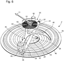
- the altitude measuring device comprises an atmospheric pressure sensor 2 arranged to deform geometrically in a rectilinear direction under the effect of a fluctuation of the pressure. atmospheric to measure.
- the atmospheric pressure sensor 2 is preferably an aneroid type pressure sensor.
- This is a round, flat, generally metallic box, formed of two corrugated thin sheets upper 4a and lower 4b assembled together by welding. This box is waterproof since it has been sealed under partial vacuum.
- the atmospheric pressure sensor 2 compresses or expands as a function of the variations in atmospheric pressure, which causes the two upper and lower plates 4a and 4b to move closer together or away from each other.
- the deformation movements of the atmospheric pressure sensor 2 are transformed, via a transmission system 6, into a pivoting movement in a plane perpendicular to the rectilinear direction of deformation of the atmospheric pressure sensor 2 of an actuating system 8 which causes a pointer needle 10 pivoting.
- this indicator needle 10 moves next to a circular scale 12 formed on a flange 14 and graduated for example between 0 and 4000 meters in steps of 50 meters.
- This flange 14 is housed in a box 16 of a wristwatch 18 and can be pivotally driven by the user by means of a rotating bezel 20. It will be noted that in the example shown in the drawing, the atmospheric pressure sensor 2 is deformed in a vertical rectilinear direction.
- the transmission system 6 comprises a probe 22 formed of an arm 24 which, preferably but not exclusively, is provided at its free end with a wheel 26 through which the probe 22 is in contact with the upper plate 4a of the sensor 2.
- a washer 28 on which the wheel 26 bears is attached to the upper plate 4a of the atmospheric pressure sensor 2. This washer 28, as well as the wheel 26, are intended to minimize as much as possible friction forces between the probe 22 and the atmospheric pressure sensor 2 and thus improve the accuracy of the device for measuring altitude 1.
- the probe 22 is rigidly fixed to a transmission axis 30 which extends in a direction perpendicular to the rectilinear deformation direction of the atmospheric pressure sensor 2.
- the transmission axis 30 extends so horizontally.
- the transmission shaft 30 whose ends are provided with stones 32 is arranged to pivot under the effect of the deformation movements of the atmospheric pressure sensor 2 which are transmitted to it by the probe 22.
- the transmission axis 30 is mounted axially movable without clearance between a set screw 34 and an elastic blade 36 ( figure 3 ). By acting on the adjusting screw 34, it is thus possible to adjust the longitudinal position of the transmission shaft 30.
- a transmission pin 38 rigidly attached to the transmission axis 30 communicates to the actuation system 8 the deformation movements of the atmospheric pressure sensor 2.
- the actuating system 8 comprises a rake 40 against which the transmission pin 38 is supported according to a rectilinear segment 42 of contact points.
- this rectilinear segment 42 serves as a reference point during the calibration of the altitude measuring device 1.
- the altitude measuring device 1 is suitably adjusted for the altitude at the altitude. sea level when the rectilinear segment 42 of contact points extends parallel to the transmission axis 30. For this, the axial position of the transmission axis 30 is adjusted.
- the rake 40 is pivotally mounted in a horizontal plane about a vertical pivot axis 44.
- the rake 40 is provided with a toothed sector 46 in an arc which meshes with a pinion 48 integral with a tube 50 on which is mounted the indicator needle 10.
- the tube 50 can be rotated on the hour cannon of the watch movement. But in this case, we can observe friction forces that can distort the measurement. That is why it is preferred to pass the roadway inside the tube 50 without contact between the roadway and the tube 50.
- the altitude measuring device 1 comprises elastic means arranged to keep the probe 22 in constant contact with the atmospheric pressure sensor 2.
- the resilient means comprise a helical spring 52 fixed at one end to a stud 54 and at another end on the rake 40 on which it exerts an elastic return force. This elastic restoring force is transmitted to the feeler 22 via the transmission pin 38 and the transmission axis 30.
- the elastic means comprise a spring in turns 56, a curve inside 58 is fixed on the tube 50 on which is mounted the indicator needle 10 and an outer curve 60 is fixed on a peg 62 integral of the box 16 of the wristwatch 18.
- the tube 50 on which is mounted the indicator needle 10 is fixed on the inside of a ball bearing 64 itself fixed on a dial 65 of the wristwatch 18.
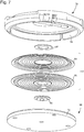
- the atmospheric pressure sensor 2 is mounted on a seat 66 which is, for example, driven out and adhered in a support 68 with the interposition of a clearance adjustment flange 70 between the atmospheric pressure sensor 2 and the support 68 ( figures 3 and 4 ).
- This support 68 is provided on its outer periphery with a first thread 72 which cooperates with a second thread 74 provided on the inner periphery of a cover 78 which, with the support 68, forms a casing 80.
- the support 68 can therefore be screwed or unscrewed, which allows to precisely adjust the height of the atmospheric pressure sensor 2 relative to the other components of the altitude measuring device 1 and thus compensate for any dimensional variations of the atmospheric pressure sensor 2 due to manufacturing tolerances .
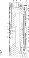
- the altitude measuring device 1 is placed inside a sealed device 82, for example of the type of a sealed tank 84 closed by an ice 86 with the interposition of a seal 88.
- Watertight tank 84 has an air intake 90 which makes it possible to adjust the pressure inside this tank 84 as required.
- the sealed tank 84 also includes first and second buttons 92 and 94 for adjusting the altitude measuring device 1. These buttons 92 and 94 can be knurled for a better grip.
- the first button 92 is extended towards the inside of the sealed tank 84 by a screwdriver blade 96 pivoted on a stone 98a by means of which one can actuate the adjusting screw 34 to adjust the axial position of the transmission shaft 30.
- a seal 100a is disposed on the screwdriver blade 96 to ensure the sealing of the passage of the first button 92.
- the second button 94 comprises a rod 102 pivoted on a stone 98b and on which is engaged a seal 100b to ensure the sealing passage of the second button 94.
- the rod 102 carries a pinion 104 which cooperates with a wheel toothed 106 which extends horizontally ( figure 10 ).
- This gear wheel 106 carries in its board two diametrically opposite pins 108 which are housed in two corresponding holes 110 formed in the support 68.
- the altitude measuring device 1 is received in the sealed tank 84 by a setting 76 provided with two holes 112 in which two pins 114 project which protrude into the bottom of the tank 84.
- a holding blade 116 retained by two screws 118 ( figure 11 ). This holding blade 116 is pierced with a hole 120 through which the screwdriver blade 96 passes and abuts on a flat surface 122 formed in the cover 78 and delimited by a straight flat wall 124 against which the holding blade 116 comes in support.
- the cover 78 is axially locked and pivoted inside the tank 84, which allows, as required, to screw or unscrew the support 68 and thus to raise or lower the atmospheric pressure sensor. 2 relative to the other components of the altitude measuring device 1 during the calibration operations of the latter.
- the ice 86 is provided with two hooks 126 which cooperate with two bolts 128 fixed on the frame 130 of the tank 84.
- the calibration of the altitude measuring device 1 according to the invention is carried out as follows.
- the altitude measuring device 1 is introduced into the tank 84.
- the altitude measuring device 1 is immobilized inside the tank 84 thanks to the holding blade 116 that is blocked by tightening the screws 118.
- the tank 84 is closed in a sealed manner by means of the locks 128 which engage with the hooks 126. It is ensured that the seal 88 is in position. square.
- the atmospheric pressure is brought inside the tank 72 to a value of 1013.25 hPa which corresponds to the average atmospheric pressure prevailing at sea level at 0 meter altitude and the position is observed. of the rectilinear segment of contact points 42 with respect to the transmission axis 30.
- the second button 94 is rotated in one direction or the other, so as to screw or unscrew the support 68 and thus move up or down the atmospheric pressure sensor 2.
- the translational movement of the atmospheric pressure sensor 2 is communicated to the rake 40 via the probe 22 and the transmission pin 38.
- the altitude measuring device 1 is suitably adjusted for the altitude at sea level when the rectilinear segment of contact points 42 extends parallel to the transmission axis 30.
- the atmospheric pressure inside the tank 84 is reduced to a value corresponding, for example, to an altitude of 4000 meters. If the pointer pointer 10 does not point to the graduation 4000 of the circular scale shown on the flange 14, the axis of rotation is displaced axially. transmission 30 by screwing or unscrewing the adjusting screw 34 by means of the first button 92.
- the calibration of the altitude measuring device 1 according to the invention is completed. To ensure this, it is sufficient, for example, to increase again the atmospheric pressure inside the tank 84 to a value corresponding to the level of the sea, and it will be seen that the pointer needle 10 points on the scale 0 of the circular scale.
- the present invention is not limited to the embodiment which has just been described and that various modifications and simple variants can be envisaged by those skilled in the art without departing from the scope of the invention as defined by the appended claims.
- the calibration operations of the altitude measuring device 1 according to the invention can be easily automated. Indeed, it is sufficient to have a camera capable of locating the position of the rectilinear segment of contact points 42 with respect to the transmission axis 30 and to identify the position of the indicator needle 10 with respect to the scale circular material 12 materialized on the flange 14. Such a camera will be completed by a device for actuating the knurled buttons 92, 94.
Landscapes
- Physics & Mathematics (AREA)
- General Physics & Mathematics (AREA)
- Engineering & Computer Science (AREA)
- Radar, Positioning & Navigation (AREA)
- Remote Sensing (AREA)
- Measuring Fluid Pressure (AREA)
- A Measuring Device Byusing Mechanical Method (AREA)
Claims (18)
- Höhenmessvorrichtung (1), umfassend einen Atmosphärendrucksensor (2), der dafür ausgelegt ist, in Abhängigkeit vom zu messenden Atmosphärendruck, der zunimmt oder abnimmt, in einer geraden Richtung zusammengedrückt oder entlastet zu werden, wobei die Verformungsbewegungen des Atmosphärendrucksensors (2) über ein Übertragungssystem (6) in eine Drehbewegung eines Betätigungssystems (8) in einer Ebene senkrecht zu der geraden Verformungsrichtung des Atmosphärendrucksensors (2) transformiert werden, wodurch ein Zeiger (10) rotatorisch angetrieben wird, wobei sich dieser Zeiger (10) gegenüber einer gestuften kreisförmigen Skala (12) verlagert, wobei der Atmosphärendrucksensor (2) dafür ausgelegt ist, in einem Richtungssinn oder in dem entgegengesetzten Richtungssinn längs seiner geraden Verformungsrichtung relativ zu den anderen Komponenten der Höhenmessvorrichtung verlagert werden zu können, dadurch gekennzeichnet, dass der Atmosphärendrucksensor (2) auf einem Sitz (66) montiert ist, der in einem Träger (68) befestigt ist, der zusammen mit einem Deckel (78) ein Gehäuse (80) bildet, wobei der Träger (68) dafür ausgelegt ist, in der geraden Verformungsrichtung des Atmosphärendrucksensors (2) relativ zu den anderen Komponenten der Höhenmessvorrichtung verlagert werden zu können, wobei der Träger (68) an seinem Außenumfang mit einem ersten Gewinde (72) versehen ist, das mit einem zweiten Gewinde (74) zusammenwirkt, das am inneren Umfang des Deckels (78) vorgesehen ist.
- Höhenmessvorrichtung nach Anspruch 1, dadurch gekennzeichnet, dass der Atmosphärendrucksensor (2) vom Aneroid-Typ ist und dass er aus zwei Blechen, einem oberen Blech (4a) und einem unteren Blech (4b) gebildet ist, die in einem Teilvakuum zusammengefügt sind.
- Höhenmessvorrichtung nach Anspruch 2, dadurch gekennzeichnet, dass das Übertragungssystem (6) einen Taster (22) umfasst, der durch einen Arm (24) gebildet ist, über dessen freies Ende sich der Taster (22) an dem oberen Blech (4a) des Atmosphärendrucksensors (2) abstützt.
- Höhenmessvorrichtung nach Anspruch 3, dadurch gekennzeichnet, dass der Arm (24) des Tasters (22) an seinem freien Ende mit einer Rolle (26) versehen ist, über die der Taster (22) mit dem oberen Blech (4a) des Atmosphärendrucksensors (2) in Kontakt ist.
- Höhenmessvorrichtung nach Anspruch 4, dadurch gekennzeichnet, dass auf dem oberen Blech (4a) des Atmosphärendrucksensors (2) eine Scheibe (28) befestigt ist, auf der sich die Rolle (26) abstützt.
- Höhenmessvorrichtung nach einem der Ansprüche 3 bis 5, dadurch gekennzeichnet, dass der Taster (22) an einem anderen Ende an einer Übertragungsachse (30) starr befestigt ist, die sich in einer Richtung senkrecht zu der geraden Verformungsrichtung des Atmosphärendrucksensors (2) erstreckt.
- Höhenmessvorrichtung nach Anspruch 6, dadurch gekennzeichnet, dass die Übertragungsachse (30) dafür ausgelegt ist, sich unter der Wirkung von Verformungsbewegungen des Atmosphärendrucksensors (2) zu drehen, die an sie über den Taster (22) übertragen werden, und dass die Übertragungsachse (30) längs ihrer longitudinalen Symmetrieachse bewegbar montiert ist.
- Höhenmessvorrichtung nach einem der Ansprüche 6 oder 7, dadurch gekennzeichnet, dass ein Übertragungsstift (38), der an der Übertragungsachse (30) starr befestigt ist, die Verformungsbewegungen des Atmosphärendrucksensors (2) auf das Betätigungssystem (8) überträgt.
- Höhenmessvorrichtung nach Anspruch 8, dadurch gekennzeichnet, dass das Betätigungssystem (8) einen Rechen (40) umfasst, gegen den sich der Übertragungsstift (38) entlang eines geradlinigen Kontaktpunktsegments (42) abstützt.
- Höhenmessvorrichtung nach Anspruch 9, dadurch gekennzeichnet, dass der Rechen (40) in einer Ebene senkrecht zu der Verformungsrichtung des Drucksensors (2) drehbar montiert ist und mit einem kreisbogenförmigen gezahnten Sektor (46) versehen ist, der mit einem Ritzel (48) kämmt, das mit einem Rohr (50) fest verbunden ist, an dem der Zeiger (10) montiert ist.
- Höhenmessvorrichtung nach Anspruch 10, dadurch gekennzeichnet, dass die Höhenmessvorrichtung (1) elastische Mittel umfasst, die dafür ausgelegt sind, den Taster (22) in ständigem Kontakt mit dem Atmosphärendrucksensor (2) zu halten.
- Höhenmessvorrichtung nach Anspruch 11, dadurch gekennzeichnet, dass die elastischen Mittel eine Schraubenfeder (52) umfassen, die auf den Rechen (40) eine elastische Rückstellkraft ausübt.
- Höhenmessvorrichtung nach Anspruch 11, dadurch gekennzeichnet, dass die elastischen Mittel eine Spiralfeder (56) umfassen, deren innere Windung (58) an dem Rohr (50), an dem der Zeiger (10) montiert ist, befestigt ist.
- Höhenmessvorrichtung nach Anspruch 13, dadurch gekennzeichnet, dass zwischen der Spiralfeder (56) und dem Rohr (50), an dem der Zeiger (10) montiert ist, ein Kugellager (64) angeordnet ist.
- Messvorrichtung nach einem der Ansprüche 1 bis 14, dadurch gekennzeichnet, dass der Träger (68) und der Atmosphärendrucksensor (2) konzentrisch sind.
- Messvorrichtung nach einem der Ansprüche 1 bis 15, dadurch gekennzeichnet, dass der Atmosphärendrucksensor (2) an dem Sitz (66) unter Einfügung eines Spiel-ausgleichenden Flansches (70) zwischen dem Atmosphärendrucksensor (2) und dem Träger (68) befestigt ist.
- Tragbarer Gegenstand, umfassend eine Höhenmessvorrichtung nach einem der vorhergehenden Ansprüche.
- Tragbarer Gegenstand nach Anspruch 17, dadurch gekennzeichnet, dass es sich um eine Armbanduhr (18) handelt.
Applications Claiming Priority (1)
| Application Number | Priority Date | Filing Date | Title |
|---|---|---|---|
| EP15182364.8A EP3136072A1 (de) | 2015-08-25 | 2015-08-25 | Höhenmessvorrichtung und tragbares objekt, das eine solche vorrichtung umfasst |
Publications (2)
| Publication Number | Publication Date |
|---|---|
| EP3136073A1 EP3136073A1 (de) | 2017-03-01 |
| EP3136073B1 true EP3136073B1 (de) | 2018-07-04 |
Family
ID=53969316
Family Applications (2)
| Application Number | Title | Priority Date | Filing Date |
|---|---|---|---|
| EP15182364.8A Withdrawn EP3136072A1 (de) | 2015-08-25 | 2015-08-25 | Höhenmessvorrichtung und tragbares objekt, das eine solche vorrichtung umfasst |
| EP16181795.2A Active EP3136073B1 (de) | 2015-08-25 | 2016-07-28 | Höhenmessvorrichtung und tragbares objekt, das eine solche vorrichtung umfasst |
Family Applications Before (1)
| Application Number | Title | Priority Date | Filing Date |
|---|---|---|---|
| EP15182364.8A Withdrawn EP3136072A1 (de) | 2015-08-25 | 2015-08-25 | Höhenmessvorrichtung und tragbares objekt, das eine solche vorrichtung umfasst |
Country Status (4)
| Country | Link |
|---|---|
| US (1) | US10295344B2 (de) |
| EP (2) | EP3136072A1 (de) |
| JP (1) | JP6276811B2 (de) |
| CN (1) | CN106482705B (de) |
Families Citing this family (3)
| Publication number | Priority date | Publication date | Assignee | Title |
|---|---|---|---|---|
| JP2017173016A (ja) * | 2016-03-22 | 2017-09-28 | セイコーエプソン株式会社 | 圧力センサー付きデバイス |
| EP4134758B1 (de) * | 2021-08-10 | 2024-04-03 | Blancpain SA | Uhrenmechanismus, der informationen über einen umgebungsdruck anzeigt und einen rückstellmechanismus umfasst, und uhr mit einem solchen mechanismus, wie z. b. eine taucheruhr |
| KR20240017596A (ko) | 2022-08-01 | 2024-02-08 | 삼성전기주식회사 | 커패시터 부품 특성 측정 장치 |
Family Cites Families (18)
| Publication number | Priority date | Publication date | Assignee | Title |
|---|---|---|---|---|
| US3040582A (en) * | 1958-11-26 | 1962-06-26 | Bendix Corp | Motion transmission mechanisms |
| US3805618A (en) * | 1972-08-11 | 1974-04-23 | Springfield Instr Co Inc | Pressure-responsive instrument |
| US3874242A (en) * | 1972-08-11 | 1975-04-01 | Springfield Instr Company Inc | Pressure-responsive instrument |
| CH601784A5 (de) * | 1976-03-12 | 1978-07-14 | Intersub Etablissement Financi | |
| DE2851359C2 (de) * | 1978-11-28 | 1987-01-08 | Dostmann Gmbh & Co Kg, 6980 Wertheim | Barometer |
| DE8015715U1 (de) * | 1980-06-13 | 1986-10-16 | Alexander Wiegand Gmbh U. Co Armaturen- U. Manometerfabrik, 8763 Klingenberg | Absolutdruckmanometer |
| JPS57147736U (de) * | 1981-03-12 | 1982-09-17 | ||
| JPS5989209U (ja) * | 1982-12-08 | 1984-06-16 | ジエコ−株式会社 | 高度計 |
| JPS60123613U (ja) * | 1984-01-31 | 1985-08-20 | カルソニックカンセイ株式会社 | アネロイド型高度計 |
| CN87216272U (zh) * | 1987-12-14 | 1988-12-07 | 陈国模 | 修正式空盒气压高度表 |
| CH687275A5 (de) * | 1993-07-09 | 1996-10-31 | Synton Ag | Messgeraet und Verfahren zur Montage desselben. |
| JP4330480B2 (ja) * | 2004-04-06 | 2009-09-16 | 長野計器株式会社 | 検出器 |
| US7350414B1 (en) * | 2004-05-11 | 2008-04-01 | Trintec Industries, Inc. | Mechanical barometer |
| CN2735320Y (zh) * | 2004-10-18 | 2005-10-19 | 四川西光工业(集团)有限公司 | 气压高度计 |
| CH700434B1 (fr) * | 2007-03-22 | 2010-08-31 | Richemont Int Sa | Dispositif de mesure de la pression pour pièce d'horlogerie et pièce d'horlogerie munie d'un tel dispositif. |
| EP2818943B1 (de) * | 2013-06-24 | 2018-04-25 | Montres Breguet SA | Tragbarer Gegenstand, der mit einer Vorrichtung zum Messen des Luftdrucks ausgestattet ist |
| CH709067B1 (de) * | 2013-12-16 | 2018-08-31 | Oris Sa | Uhr mit barometrischem Drucksensor. |
| EP3136071B1 (de) * | 2015-08-25 | 2018-03-28 | The Swatch Group Research and Development Ltd. | Kalibriervorrichtung und -verfahren einer höhenmessvorrichtung |
-
2015
- 2015-08-25 EP EP15182364.8A patent/EP3136072A1/de not_active Withdrawn
-
2016
- 2016-07-21 US US15/215,760 patent/US10295344B2/en active Active
- 2016-07-28 EP EP16181795.2A patent/EP3136073B1/de active Active
- 2016-08-05 JP JP2016154314A patent/JP6276811B2/ja active Active
- 2016-08-24 CN CN201610716426.6A patent/CN106482705B/zh active Active
Non-Patent Citations (1)
| Title |
|---|
| None * |
Also Published As
| Publication number | Publication date |
|---|---|
| US10295344B2 (en) | 2019-05-21 |
| JP6276811B2 (ja) | 2018-02-07 |
| CN106482705A (zh) | 2017-03-08 |
| EP3136073A1 (de) | 2017-03-01 |
| JP2017044690A (ja) | 2017-03-02 |
| US20170059315A1 (en) | 2017-03-02 |
| EP3136072A1 (de) | 2017-03-01 |
| CN106482705B (zh) | 2020-04-03 |
Similar Documents
| Publication | Publication Date | Title |
|---|---|---|
| EP3136071B1 (de) | Kalibriervorrichtung und -verfahren einer höhenmessvorrichtung | |
| EP3136073B1 (de) | Höhenmessvorrichtung und tragbares objekt, das eine solche vorrichtung umfasst | |
| EP1470452B1 (de) | Vorrichtung mit uhrwerk und chronographenmodul | |
| EP0713162B1 (de) | Uhr mit Vorrichtung zur Bestimmung der erdmagnetischen Nordrichtung | |
| CH685659B5 (fr) | Montre indiquant une prevision meteorologique. | |
| EP0452757B1 (de) | Mechanische oder elektromechanische Kompassuhr | |
| EP2818943B1 (de) | Tragbarer Gegenstand, der mit einer Vorrichtung zum Messen des Luftdrucks ausgestattet ist | |
| CH707513B1 (fr) | Montre-bracelet à complication mécanique comprenant au moins une capsule anéroïde. | |
| EP2339410B1 (de) | Dynamometrische Vorrichtung zur Anzeige der Drehmomentreserve des Federgehäuses einer Uhr | |
| EP1960845B1 (de) | Tiefenmesseinrichtung für eine uhr und uhr mit einer solchen messeinrichtung | |
| CH711447A2 (fr) | Dispositif de mesure de l'altitude et objet portable comprenant un tel dispositif. | |
| CH711446A2 (fr) | Dispositif et procédé d'étalonnage d'un dispositif de mesure de l'altitude. | |
| CH700434B1 (fr) | Dispositif de mesure de la pression pour pièce d'horlogerie et pièce d'horlogerie munie d'un tel dispositif. | |
| CH711768A2 (fr) | Dispositif d'embrayage bidirectionnel à débrayage dynamométrique unidirectionnel pour pièce d'horlogerie. | |
| CH708225A2 (fr) | Objet portable, tel qu'une montre-bracelet, équipé d'un dispositif de mesure de la pression atmosphérique. | |
| EP4134758A1 (de) | Uhrenmechanismus, der informationen über einen umgebungsdruck anzeigt und einen rückstellmechanismus umfasst, und uhr mit einem solchen mechanismus, wie z. b. eine taucheruhr | |
| FR2969324A1 (fr) | Montre-bracelet equipee d'une capsule aneroide. | |
| CH718881A2 (fr) | Mécanisme de pièce d'horlogerie indiquant une information relative à une pression environnante comportant un mécanisme de remise à zéro et pièce d'horlogerie, telle qu'une montre de plongée comportant un tel mécanisme. | |
| CH700334B1 (fr) | Pièce d'horlogerie comportant un dispositif de mesure, notamment de la pression. | |
| EP3032266A1 (de) | Uhr, die ein windmessermodul umfasst | |
| CH190758A (fr) | Altimètre. | |
| CH702430A2 (fr) | Dispositif dynamométrique indicateur de réserve de couple de barillet de pièce d'horlogerie. | |
| CH401532A (fr) | Baromètre ou altimètre anéroïde | |
| CH651172GA3 (fr) | Méchanisme indicateur des phases de lune pour mouvement d'horlogerie |
Legal Events
| Date | Code | Title | Description |
|---|---|---|---|
| PUAI | Public reference made under article 153(3) epc to a published international application that has entered the european phase |
Free format text: ORIGINAL CODE: 0009012 |
|
| AK | Designated contracting states |
Kind code of ref document: A1 Designated state(s): AL AT BE BG CH CY CZ DE DK EE ES FI FR GB GR HR HU IE IS IT LI LT LU LV MC MK MT NL NO PL PT RO RS SE SI SK SM TR |
|
| AX | Request for extension of the european patent |
Extension state: BA ME |
|
| 17P | Request for examination filed |
Effective date: 20170126 |
|
| 17Q | First examination report despatched |
Effective date: 20170412 |
|
| RBV | Designated contracting states (corrected) |
Designated state(s): AL AT BE BG CH CY CZ DE DK EE ES FI FR GB GR HR HU IE IS IT LI LT LU LV MC MK MT NL NO PL PT RO RS SE SI SK SM TR |
|
| GRAP | Despatch of communication of intention to grant a patent |
Free format text: ORIGINAL CODE: EPIDOSNIGR1 |
|
| INTG | Intention to grant announced |
Effective date: 20180209 |
|
| GRAS | Grant fee paid |
Free format text: ORIGINAL CODE: EPIDOSNIGR3 |
|
| GRAJ | Information related to disapproval of communication of intention to grant by the applicant or resumption of examination proceedings by the epo deleted |
Free format text: ORIGINAL CODE: EPIDOSDIGR1 |
|
| GRAL | Information related to payment of fee for publishing/printing deleted |
Free format text: ORIGINAL CODE: EPIDOSDIGR3 |
|
| INTC | Intention to grant announced (deleted) | ||
| GRAR | Information related to intention to grant a patent recorded |
Free format text: ORIGINAL CODE: EPIDOSNIGR71 |
|
| GRAA | (expected) grant |
Free format text: ORIGINAL CODE: 0009210 |
|
| AK | Designated contracting states |
Kind code of ref document: B1 Designated state(s): AL AT BE BG CH CY CZ DE DK EE ES FI FR GB GR HR HU IE IS IT LI LT LU LV MC MK MT NL NO PL PT RO RS SE SI SK SM TR |
|
| INTG | Intention to grant announced |
Effective date: 20180529 |
|
| REG | Reference to a national code |
Ref country code: GB Ref legal event code: FG4D Free format text: NOT ENGLISH |
|
| REG | Reference to a national code |
Ref country code: CH Ref legal event code: EP Ref country code: CH Ref legal event code: NV Representative=s name: ICB INGENIEURS CONSEILS EN BREVETS SA, CH |
|
| REG | Reference to a national code |
Ref country code: AT Ref legal event code: REF Ref document number: 1015022 Country of ref document: AT Kind code of ref document: T Effective date: 20180715 |
|
| REG | Reference to a national code |
Ref country code: IE Ref legal event code: FG4D Free format text: LANGUAGE OF EP DOCUMENT: FRENCH |
|
| REG | Reference to a national code |
Ref country code: DE Ref legal event code: R096 Ref document number: 602016003941 Country of ref document: DE |
|
| REG | Reference to a national code |
Ref country code: FR Ref legal event code: PLFP Year of fee payment: 3 |
|
| REG | Reference to a national code |
Ref country code: NL Ref legal event code: MP Effective date: 20180704 |
|
| REG | Reference to a national code |
Ref country code: LT Ref legal event code: MG4D |
|
| REG | Reference to a national code |
Ref country code: AT Ref legal event code: MK05 Ref document number: 1015022 Country of ref document: AT Kind code of ref document: T Effective date: 20180704 |
|
| PG25 | Lapsed in a contracting state [announced via postgrant information from national office to epo] |
Ref country code: NL Free format text: LAPSE BECAUSE OF FAILURE TO SUBMIT A TRANSLATION OF THE DESCRIPTION OR TO PAY THE FEE WITHIN THE PRESCRIBED TIME-LIMIT Effective date: 20180704 |
|
| PG25 | Lapsed in a contracting state [announced via postgrant information from national office to epo] |
Ref country code: SE Free format text: LAPSE BECAUSE OF FAILURE TO SUBMIT A TRANSLATION OF THE DESCRIPTION OR TO PAY THE FEE WITHIN THE PRESCRIBED TIME-LIMIT Effective date: 20180704 Ref country code: AT Free format text: LAPSE BECAUSE OF FAILURE TO SUBMIT A TRANSLATION OF THE DESCRIPTION OR TO PAY THE FEE WITHIN THE PRESCRIBED TIME-LIMIT Effective date: 20180704 Ref country code: NO Free format text: LAPSE BECAUSE OF FAILURE TO SUBMIT A TRANSLATION OF THE DESCRIPTION OR TO PAY THE FEE WITHIN THE PRESCRIBED TIME-LIMIT Effective date: 20181004 Ref country code: BG Free format text: LAPSE BECAUSE OF FAILURE TO SUBMIT A TRANSLATION OF THE DESCRIPTION OR TO PAY THE FEE WITHIN THE PRESCRIBED TIME-LIMIT Effective date: 20181004 Ref country code: IS Free format text: LAPSE BECAUSE OF FAILURE TO SUBMIT A TRANSLATION OF THE DESCRIPTION OR TO PAY THE FEE WITHIN THE PRESCRIBED TIME-LIMIT Effective date: 20181104 Ref country code: RS Free format text: LAPSE BECAUSE OF FAILURE TO SUBMIT A TRANSLATION OF THE DESCRIPTION OR TO PAY THE FEE WITHIN THE PRESCRIBED TIME-LIMIT Effective date: 20180704 Ref country code: FI Free format text: LAPSE BECAUSE OF FAILURE TO SUBMIT A TRANSLATION OF THE DESCRIPTION OR TO PAY THE FEE WITHIN THE PRESCRIBED TIME-LIMIT Effective date: 20180704 Ref country code: GR Free format text: LAPSE BECAUSE OF FAILURE TO SUBMIT A TRANSLATION OF THE DESCRIPTION OR TO PAY THE FEE WITHIN THE PRESCRIBED TIME-LIMIT Effective date: 20181005 Ref country code: CZ Free format text: LAPSE BECAUSE OF FAILURE TO SUBMIT A TRANSLATION OF THE DESCRIPTION OR TO PAY THE FEE WITHIN THE PRESCRIBED TIME-LIMIT Effective date: 20180704 Ref country code: PL Free format text: LAPSE BECAUSE OF FAILURE TO SUBMIT A TRANSLATION OF THE DESCRIPTION OR TO PAY THE FEE WITHIN THE PRESCRIBED TIME-LIMIT Effective date: 20180704 Ref country code: LT Free format text: LAPSE BECAUSE OF FAILURE TO SUBMIT A TRANSLATION OF THE DESCRIPTION OR TO PAY THE FEE WITHIN THE PRESCRIBED TIME-LIMIT Effective date: 20180704 |
|
| PG25 | Lapsed in a contracting state [announced via postgrant information from national office to epo] |
Ref country code: ES Free format text: LAPSE BECAUSE OF FAILURE TO SUBMIT A TRANSLATION OF THE DESCRIPTION OR TO PAY THE FEE WITHIN THE PRESCRIBED TIME-LIMIT Effective date: 20180704 Ref country code: HR Free format text: LAPSE BECAUSE OF FAILURE TO SUBMIT A TRANSLATION OF THE DESCRIPTION OR TO PAY THE FEE WITHIN THE PRESCRIBED TIME-LIMIT Effective date: 20180704 Ref country code: AL Free format text: LAPSE BECAUSE OF FAILURE TO SUBMIT A TRANSLATION OF THE DESCRIPTION OR TO PAY THE FEE WITHIN THE PRESCRIBED TIME-LIMIT Effective date: 20180704 Ref country code: LV Free format text: LAPSE BECAUSE OF FAILURE TO SUBMIT A TRANSLATION OF THE DESCRIPTION OR TO PAY THE FEE WITHIN THE PRESCRIBED TIME-LIMIT Effective date: 20180704 |
|
| PG25 | Lapsed in a contracting state [announced via postgrant information from national office to epo] |
Ref country code: LU Free format text: LAPSE BECAUSE OF NON-PAYMENT OF DUE FEES Effective date: 20180728 |
|
| REG | Reference to a national code |
Ref country code: BE Ref legal event code: MM Effective date: 20180731 |
|
| REG | Reference to a national code |
Ref country code: DE Ref legal event code: R097 Ref document number: 602016003941 Country of ref document: DE |
|
| PG25 | Lapsed in a contracting state [announced via postgrant information from national office to epo] |
Ref country code: RO Free format text: LAPSE BECAUSE OF FAILURE TO SUBMIT A TRANSLATION OF THE DESCRIPTION OR TO PAY THE FEE WITHIN THE PRESCRIBED TIME-LIMIT Effective date: 20180704 Ref country code: MC Free format text: LAPSE BECAUSE OF FAILURE TO SUBMIT A TRANSLATION OF THE DESCRIPTION OR TO PAY THE FEE WITHIN THE PRESCRIBED TIME-LIMIT Effective date: 20180704 Ref country code: EE Free format text: LAPSE BECAUSE OF FAILURE TO SUBMIT A TRANSLATION OF THE DESCRIPTION OR TO PAY THE FEE WITHIN THE PRESCRIBED TIME-LIMIT Effective date: 20180704 Ref country code: IT Free format text: LAPSE BECAUSE OF FAILURE TO SUBMIT A TRANSLATION OF THE DESCRIPTION OR TO PAY THE FEE WITHIN THE PRESCRIBED TIME-LIMIT Effective date: 20180704 |
|
| REG | Reference to a national code |
Ref country code: IE Ref legal event code: MM4A |
|
| PLBE | No opposition filed within time limit |
Free format text: ORIGINAL CODE: 0009261 |
|
| STAA | Information on the status of an ep patent application or granted ep patent |
Free format text: STATUS: NO OPPOSITION FILED WITHIN TIME LIMIT |
|
| PG25 | Lapsed in a contracting state [announced via postgrant information from national office to epo] |
Ref country code: SK Free format text: LAPSE BECAUSE OF FAILURE TO SUBMIT A TRANSLATION OF THE DESCRIPTION OR TO PAY THE FEE WITHIN THE PRESCRIBED TIME-LIMIT Effective date: 20180704 Ref country code: SM Free format text: LAPSE BECAUSE OF FAILURE TO SUBMIT A TRANSLATION OF THE DESCRIPTION OR TO PAY THE FEE WITHIN THE PRESCRIBED TIME-LIMIT Effective date: 20180704 Ref country code: DK Free format text: LAPSE BECAUSE OF FAILURE TO SUBMIT A TRANSLATION OF THE DESCRIPTION OR TO PAY THE FEE WITHIN THE PRESCRIBED TIME-LIMIT Effective date: 20180704 Ref country code: BE Free format text: LAPSE BECAUSE OF NON-PAYMENT OF DUE FEES Effective date: 20180731 |
|
| 26N | No opposition filed |
Effective date: 20190405 |
|
| PG25 | Lapsed in a contracting state [announced via postgrant information from national office to epo] |
Ref country code: IE Free format text: LAPSE BECAUSE OF NON-PAYMENT OF DUE FEES Effective date: 20180728 |
|
| PG25 | Lapsed in a contracting state [announced via postgrant information from national office to epo] |
Ref country code: SI Free format text: LAPSE BECAUSE OF FAILURE TO SUBMIT A TRANSLATION OF THE DESCRIPTION OR TO PAY THE FEE WITHIN THE PRESCRIBED TIME-LIMIT Effective date: 20180704 |
|
| PG25 | Lapsed in a contracting state [announced via postgrant information from national office to epo] |
Ref country code: MT Free format text: LAPSE BECAUSE OF FAILURE TO SUBMIT A TRANSLATION OF THE DESCRIPTION OR TO PAY THE FEE WITHIN THE PRESCRIBED TIME-LIMIT Effective date: 20180704 |
|
| PG25 | Lapsed in a contracting state [announced via postgrant information from national office to epo] |
Ref country code: TR Free format text: LAPSE BECAUSE OF FAILURE TO SUBMIT A TRANSLATION OF THE DESCRIPTION OR TO PAY THE FEE WITHIN THE PRESCRIBED TIME-LIMIT Effective date: 20180704 |
|
| PG25 | Lapsed in a contracting state [announced via postgrant information from national office to epo] |
Ref country code: PT Free format text: LAPSE BECAUSE OF FAILURE TO SUBMIT A TRANSLATION OF THE DESCRIPTION OR TO PAY THE FEE WITHIN THE PRESCRIBED TIME-LIMIT Effective date: 20180704 |
|
| PG25 | Lapsed in a contracting state [announced via postgrant information from national office to epo] |
Ref country code: CY Free format text: LAPSE BECAUSE OF FAILURE TO SUBMIT A TRANSLATION OF THE DESCRIPTION OR TO PAY THE FEE WITHIN THE PRESCRIBED TIME-LIMIT Effective date: 20180704 Ref country code: MK Free format text: LAPSE BECAUSE OF NON-PAYMENT OF DUE FEES Effective date: 20180704 Ref country code: HU Free format text: LAPSE BECAUSE OF FAILURE TO SUBMIT A TRANSLATION OF THE DESCRIPTION OR TO PAY THE FEE WITHIN THE PRESCRIBED TIME-LIMIT; INVALID AB INITIO Effective date: 20160728 |
|
| P01 | Opt-out of the competence of the unified patent court (upc) registered |
Effective date: 20230615 |
|
| PGFP | Annual fee paid to national office [announced via postgrant information from national office to epo] |
Ref country code: CH Payment date: 20230801 Year of fee payment: 8 |
|
| PGFP | Annual fee paid to national office [announced via postgrant information from national office to epo] |
Ref country code: DE Payment date: 20230620 Year of fee payment: 8 |
|
| PGFP | Annual fee paid to national office [announced via postgrant information from national office to epo] |
Ref country code: GB Payment date: 20240620 Year of fee payment: 9 |
|
| PGFP | Annual fee paid to national office [announced via postgrant information from national office to epo] |
Ref country code: FR Payment date: 20240619 Year of fee payment: 9 |