EP3136016A1 - Hybrid-solarkollektor sowie verfahren zu dessen betrieb - Google Patents
Hybrid-solarkollektor sowie verfahren zu dessen betrieb Download PDFInfo
- Publication number
- EP3136016A1 EP3136016A1 EP15405053.8A EP15405053A EP3136016A1 EP 3136016 A1 EP3136016 A1 EP 3136016A1 EP 15405053 A EP15405053 A EP 15405053A EP 3136016 A1 EP3136016 A1 EP 3136016A1
- Authority
- EP
- European Patent Office
- Prior art keywords
- hybrid solar
- solar collector
- collector
- air
- exhaust
- Prior art date
- Legal status (The legal status is an assumption and is not a legal conclusion. Google has not performed a legal analysis and makes no representation as to the accuracy of the status listed.)
- Granted
Links
Images


Classifications
-
- H—ELECTRICITY
- H02—GENERATION; CONVERSION OR DISTRIBUTION OF ELECTRIC POWER
- H02S—GENERATION OF ELECTRIC POWER BY CONVERSION OF INFRARED RADIATION, VISIBLE LIGHT OR ULTRAVIOLET LIGHT, e.g. USING PHOTOVOLTAIC [PV] MODULES
- H02S40/00—Components or accessories in combination with PV modules, not provided for in groups H02S10/00 - H02S30/00
- H02S40/40—Thermal components
- H02S40/44—Means to utilise heat energy, e.g. hybrid systems producing warm water and electricity at the same time
-
- F—MECHANICAL ENGINEERING; LIGHTING; HEATING; WEAPONS; BLASTING
- F24—HEATING; RANGES; VENTILATING
- F24S—SOLAR HEAT COLLECTORS; SOLAR HEAT SYSTEMS
- F24S20/00—Solar heat collectors specially adapted for particular uses or environments
- F24S20/20—Solar heat collectors for receiving concentrated solar energy, e.g. receivers for solar power plants
- F24S20/25—Solar heat collectors for receiving concentrated solar energy, e.g. receivers for solar power plants using direct solar radiation in combination with concentrated radiation
-
- F—MECHANICAL ENGINEERING; LIGHTING; HEATING; WEAPONS; BLASTING
- F24—HEATING; RANGES; VENTILATING
- F24S—SOLAR HEAT COLLECTORS; SOLAR HEAT SYSTEMS
- F24S20/00—Solar heat collectors specially adapted for particular uses or environments
- F24S20/60—Solar heat collectors integrated in fixed constructions, e.g. in buildings
- F24S20/66—Solar heat collectors integrated in fixed constructions, e.g. in buildings in the form of facade constructions, e.g. wall constructions
-
- F—MECHANICAL ENGINEERING; LIGHTING; HEATING; WEAPONS; BLASTING
- F24—HEATING; RANGES; VENTILATING
- F24S—SOLAR HEAT COLLECTORS; SOLAR HEAT SYSTEMS
- F24S60/00—Arrangements for storing heat collected by solar heat collectors
-
- H—ELECTRICITY
- H02—GENERATION; CONVERSION OR DISTRIBUTION OF ELECTRIC POWER
- H02S—GENERATION OF ELECTRIC POWER BY CONVERSION OF INFRARED RADIATION, VISIBLE LIGHT OR ULTRAVIOLET LIGHT, e.g. USING PHOTOVOLTAIC [PV] MODULES
- H02S40/00—Components or accessories in combination with PV modules, not provided for in groups H02S10/00 - H02S30/00
- H02S40/20—Optical components
- H02S40/22—Light-reflecting or light-concentrating means
-
- H—ELECTRICITY
- H10—SEMICONDUCTOR DEVICES; ELECTRIC SOLID-STATE DEVICES NOT OTHERWISE PROVIDED FOR
- H10F—INORGANIC SEMICONDUCTOR DEVICES SENSITIVE TO INFRARED RADIATION, LIGHT, ELECTROMAGNETIC RADIATION OF SHORTER WAVELENGTH OR CORPUSCULAR RADIATION
- H10F10/00—Individual photovoltaic cells, e.g. solar cells
- H10F10/10—Individual photovoltaic cells, e.g. solar cells having potential barriers
- H10F10/14—Photovoltaic cells having only PN homojunction potential barriers
- H10F10/148—Double-emitter photovoltaic cells, e.g. bifacial photovoltaic cells
-
- F—MECHANICAL ENGINEERING; LIGHTING; HEATING; WEAPONS; BLASTING
- F24—HEATING; RANGES; VENTILATING
- F24S—SOLAR HEAT COLLECTORS; SOLAR HEAT SYSTEMS
- F24S80/00—Details, accessories or component parts of solar heat collectors not provided for in groups F24S10/00-F24S70/00
- F24S2080/01—Selection of particular materials
- F24S2080/017—Natural materials, e.g. wood
-
- Y—GENERAL TAGGING OF NEW TECHNOLOGICAL DEVELOPMENTS; GENERAL TAGGING OF CROSS-SECTIONAL TECHNOLOGIES SPANNING OVER SEVERAL SECTIONS OF THE IPC; TECHNICAL SUBJECTS COVERED BY FORMER USPC CROSS-REFERENCE ART COLLECTIONS [XRACs] AND DIGESTS
- Y02—TECHNOLOGIES OR APPLICATIONS FOR MITIGATION OR ADAPTATION AGAINST CLIMATE CHANGE
- Y02B—CLIMATE CHANGE MITIGATION TECHNOLOGIES RELATED TO BUILDINGS, e.g. HOUSING, HOUSE APPLIANCES OR RELATED END-USER APPLICATIONS
- Y02B10/00—Integration of renewable energy sources in buildings
- Y02B10/10—Photovoltaic [PV]
-
- Y—GENERAL TAGGING OF NEW TECHNOLOGICAL DEVELOPMENTS; GENERAL TAGGING OF CROSS-SECTIONAL TECHNOLOGIES SPANNING OVER SEVERAL SECTIONS OF THE IPC; TECHNICAL SUBJECTS COVERED BY FORMER USPC CROSS-REFERENCE ART COLLECTIONS [XRACs] AND DIGESTS
- Y02—TECHNOLOGIES OR APPLICATIONS FOR MITIGATION OR ADAPTATION AGAINST CLIMATE CHANGE
- Y02B—CLIMATE CHANGE MITIGATION TECHNOLOGIES RELATED TO BUILDINGS, e.g. HOUSING, HOUSE APPLIANCES OR RELATED END-USER APPLICATIONS
- Y02B10/00—Integration of renewable energy sources in buildings
- Y02B10/20—Solar thermal
-
- Y—GENERAL TAGGING OF NEW TECHNOLOGICAL DEVELOPMENTS; GENERAL TAGGING OF CROSS-SECTIONAL TECHNOLOGIES SPANNING OVER SEVERAL SECTIONS OF THE IPC; TECHNICAL SUBJECTS COVERED BY FORMER USPC CROSS-REFERENCE ART COLLECTIONS [XRACs] AND DIGESTS
- Y02—TECHNOLOGIES OR APPLICATIONS FOR MITIGATION OR ADAPTATION AGAINST CLIMATE CHANGE
- Y02B—CLIMATE CHANGE MITIGATION TECHNOLOGIES RELATED TO BUILDINGS, e.g. HOUSING, HOUSE APPLIANCES OR RELATED END-USER APPLICATIONS
- Y02B10/00—Integration of renewable energy sources in buildings
- Y02B10/70—Hybrid systems, e.g. uninterruptible or back-up power supplies integrating renewable energies
-
- Y—GENERAL TAGGING OF NEW TECHNOLOGICAL DEVELOPMENTS; GENERAL TAGGING OF CROSS-SECTIONAL TECHNOLOGIES SPANNING OVER SEVERAL SECTIONS OF THE IPC; TECHNICAL SUBJECTS COVERED BY FORMER USPC CROSS-REFERENCE ART COLLECTIONS [XRACs] AND DIGESTS
- Y02—TECHNOLOGIES OR APPLICATIONS FOR MITIGATION OR ADAPTATION AGAINST CLIMATE CHANGE
- Y02E—REDUCTION OF GREENHOUSE GAS [GHG] EMISSIONS, RELATED TO ENERGY GENERATION, TRANSMISSION OR DISTRIBUTION
- Y02E10/00—Energy generation through renewable energy sources
- Y02E10/40—Solar thermal energy, e.g. solar towers
- Y02E10/44—Heat exchange systems
-
- Y—GENERAL TAGGING OF NEW TECHNOLOGICAL DEVELOPMENTS; GENERAL TAGGING OF CROSS-SECTIONAL TECHNOLOGIES SPANNING OVER SEVERAL SECTIONS OF THE IPC; TECHNICAL SUBJECTS COVERED BY FORMER USPC CROSS-REFERENCE ART COLLECTIONS [XRACs] AND DIGESTS
- Y02—TECHNOLOGIES OR APPLICATIONS FOR MITIGATION OR ADAPTATION AGAINST CLIMATE CHANGE
- Y02E—REDUCTION OF GREENHOUSE GAS [GHG] EMISSIONS, RELATED TO ENERGY GENERATION, TRANSMISSION OR DISTRIBUTION
- Y02E10/00—Energy generation through renewable energy sources
- Y02E10/50—Photovoltaic [PV] energy
- Y02E10/52—PV systems with concentrators
-
- Y—GENERAL TAGGING OF NEW TECHNOLOGICAL DEVELOPMENTS; GENERAL TAGGING OF CROSS-SECTIONAL TECHNOLOGIES SPANNING OVER SEVERAL SECTIONS OF THE IPC; TECHNICAL SUBJECTS COVERED BY FORMER USPC CROSS-REFERENCE ART COLLECTIONS [XRACs] AND DIGESTS
- Y02—TECHNOLOGIES OR APPLICATIONS FOR MITIGATION OR ADAPTATION AGAINST CLIMATE CHANGE
- Y02E—REDUCTION OF GREENHOUSE GAS [GHG] EMISSIONS, RELATED TO ENERGY GENERATION, TRANSMISSION OR DISTRIBUTION
- Y02E10/00—Energy generation through renewable energy sources
- Y02E10/50—Photovoltaic [PV] energy
- Y02E10/547—Monocrystalline silicon PV cells
-
- Y—GENERAL TAGGING OF NEW TECHNOLOGICAL DEVELOPMENTS; GENERAL TAGGING OF CROSS-SECTIONAL TECHNOLOGIES SPANNING OVER SEVERAL SECTIONS OF THE IPC; TECHNICAL SUBJECTS COVERED BY FORMER USPC CROSS-REFERENCE ART COLLECTIONS [XRACs] AND DIGESTS
- Y02—TECHNOLOGIES OR APPLICATIONS FOR MITIGATION OR ADAPTATION AGAINST CLIMATE CHANGE
- Y02E—REDUCTION OF GREENHOUSE GAS [GHG] EMISSIONS, RELATED TO ENERGY GENERATION, TRANSMISSION OR DISTRIBUTION
- Y02E10/00—Energy generation through renewable energy sources
- Y02E10/60—Thermal-PV hybrids
Definitions
- the invention relates to a hybrid solar collector according to claim 1 and a method according to claim 10.
- a solar cell with solar collector and storage elements is known ( WO-A1-99 / 54669 ) and has achieved several solar prices in its architectural realization (LUCIDO ® , trademark of Lucido solar AG, CH-9500 Wil / SG).
- a thermal solar collector is provided with a structure which acts as an angle of incidence and is provided with a transparent, ventilated cover and is hung on a thermally insulated facade of a house.
- the radiated solar energy is targeted, according to the heat capacity and heat conduction of the components, time-shifted by four to twelve hours into the interior of the room where it creates a pleasant climate with tempered wall surfaces and a corresponding energy gain.
- the hybrid solar collector should be aesthetically pleasing and visually adaptable by suitable structures to the environment and to the structure to be supplied.
- the subject invention should be able to take into account and compensate for the currently prevailing daytime climatic conditions, without a huge technical effort is required. It also aims to reduce the dependency on the power grid and at least temporarily eliminate its feed-in.
- the cover may be partially transparent (volume flow) or merely transparent (translucent). In any case, the cover must be designed so that infrared radiation can impinge on the collector, so that a delayed heat conduction is ensured inside the house.
- the operating method according to claim 10 to 12 increases the energy gain and in particular uses the radiation maxima of the sun and ensures their use and storage over the course of the day.
- the subject of the invention utilizes the hot air produced in the air gap between the collector and the cover, which has hitherto been discharged on the roof side, for the generation of energy.
- the PV elements are cooled and on the other hand prevents unwanted heat input into the house inside.
- the teaching according to the invention makes it possible to build so-called energy-plus houses without the need for thermal and electrical solar systems on the roof and / or in the garden.
- the use of the radiation reflected at the collector, according to claim 5 and 6, increases in conjunction with multilayer PV elements, the yield of electrical energy by up to 30% compared to a simple PV.
- the incident angle-dependent shading can be realized according to claim 7, at least partially, by a horizontal, strip-shaped design of the PV elements.
- PV elements according to claim 9 can with a technology according to WO-A1- 2015/091698 be configured, resulting in almost limitless design options and allows an optimal visual adaptation of the appearance of facades to the environment and / or the perception of the viewer.
- the operating method according to claim 10 to 12 use the entire conventional building services and increase their efficiency and their temporal energy availability.
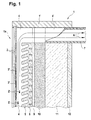
- FIG. 1 is one of the solar radiation exposed module of a hybrid solar collector designated 1.
- Front side inserted into a module frame 1 'made of wood is a multilayer cover 2 made of glass, in the strip-shaped, spaced-apart PV elements 3' are included. These are electrically connected to each other in a notoriously known manner and generate directly used DC voltage (regulated battery charge) or feed either via inverters power supplies.
- DC voltage regulated battery charge
- the subsequent insulation consists of a diffusion-open separating layer 9, hygroscopic plates 10 (natural fiber reinforced clay), rock wool 11 and gypsum boards 12.
- the insulation works by heat conduction basically identical to the mentioned prior art. - Surprisingly, this is energetically equivalent, despite the shading by the PV elements 3 '.- measurements have shown that by the shading of the PV elements 3', the heat input into the house in practice only by a U value of 0 , 09 W / m 2 ⁇ K deteriorates.
- high-performance PV elements such as so-called Bifacial Cells (Neo Solar Power Corporation, 30078 Taiwan).
- Bifacial Cells Na Solar Power Corporation, 30078 Taiwan.
- Particularly efficient are third-generation PV elements in heterojunction technology ("HAST” a cooperation of the Meyer Burger Group, Meyer Burger AG, CH-3645 Gwatt with CSEM SA, CH-2002 Neucbirtel) using the Smart Wire Connection Technology "SWCT "; see. et al Publication Swiss Federal Office of Energy SFOE, CH-3003 Bern, 05/2014.
- HAST a cooperation of the Meyer Burger Group, Meyer Burger AG, CH-3645 Gwatt with CSEM SA, CH-2002 Neucbirtel
- SWCT Smart Wire Connection Technology
- collectors 5 made of wood according to Fig. 2 which have in the horizontal longitudinal direction para-bole cutouts 20, which are each covered in the lower region with a metallic foil 21. This is a largely independent of the position of the sun reflection on the remote from the sunny side bidirectional
- the existing scattered radiation is detected as heat in the upper region of the cutout 20 and drawn off via air outlets 7 'and exhaust air pipes 7. Due to the relatively high mass of the collector 5 shown here, the insulation on rockwool 11 and a gypsum board 12 reduced.
- hybrid solar collectors 1a are equipped with wooden collectors 5 and can be manufactured correspondingly easily, such require according to 1b to 1e ( FIG. 3 to FIG. 5 ) made of ceramic consuming manufacturing means.
- Ceramic collectors can be produced in one piece with optimized reflection noses 5 "in the extrusion process (continuous casting).
- Fig. 6 can be front glazed colored, fully or partially glazed and / or mirrored. This type of coating is designated 21 '.
- their heat capacity compared to wood is about twice as high.
- a disadvantage is their low storage capacity of water, so that the desired seasonally dependent heat conduction of wood collectors usually does not set.
- their price, in relation to collectors made of wood is high.
- Ceramic collectors 5a, 5b and 5c have the known from hollow bricks (insulating bricks) cavities 50 and give correspondingly high insulation values, which can reduce the thickness of facades of facades.
- Fig. 3-6 the bidirectionally acting PV elements 3 "shown only simplified.
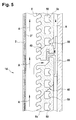
- suitable commercially available supports 60 (Alphaton ® horizontal support profiles; trademark of Moeding Keramikankaden GmbH, D-Marklkofen) is such panels can be mounted 5b via their sloping surfaces 40 and slightly stick together form-locking; please refer Fig. 5 ,
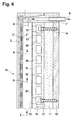
- a flat, glazed ceramic collector 5c is fastened via bores 13, 13 'on its insulation by means of suitable screws 14.
- the entire front surface of the collector 5c is provided with a reflective glaze 21 '.
- the incident angle selective effect at the collector 5c is achieved here by high opacity PV elements.
- a disadvantage of this variant is the low hygroscopicity of the layer structure, so that the desired, seasonally dependent thermal conductivity is minimal.
- a certain improvement and a temperature increase of the warm air flow A can be achieved by spacer elements between the collector 5c and insulation (rockwool 11 and gypsum board 12) (not shown), so that here also a rear ventilation with a parallel flow can occur.
- connections 74 and 75 lead to a heat exchanger, which ensures hot water deliveries in a temperature-layered storage tank (solar storage tank), even outside the sun's rays.
- the cooled in the heat pump 80 exhaust air A 'is discharged through a vertical exhaust pipe 85 with protective hood 86 into the open.
- the memory can also be additionally heated (reheated) by means of a built-in resistance heater, which corresponds to energy storage in solar peak periods.
- the air quantity controlled via a compressor in the heat pump 80 it is possible by controlling the supply air Z in the air gap 4 (FIG. Fig. 1 . Fig. 2 ) the volume of hot air flow A also be regulated.
- An additional fresh air supply can also be used to realize a temperature control that is tailored to the required air changes in the house. Thus, a simple comfort ventilation and heating support can be established.
- a control of the supply air Z in the air gap 4 can also be used for forced cooling of the solar collectors, when prevail in high summer extreme irradiation conditions. This increases the efficiency of the PV elements and, at the same time, also reduces the heat input into the interior of the house with simple means and thus the living comfort increased, without the use of power-hungry refrigerators (air conditioning).
- the subject invention is fundamentally modular and can also be retrofitted in existing buildings, especially in those with angle of incidence selective solar panels after WO-A1-99 / 54669 be retrofitted.
Landscapes
- Engineering & Computer Science (AREA)
- Life Sciences & Earth Sciences (AREA)
- Sustainable Energy (AREA)
- Physics & Mathematics (AREA)
- Sustainable Development (AREA)
- Thermal Sciences (AREA)
- Chemical & Material Sciences (AREA)
- Combustion & Propulsion (AREA)
- Mechanical Engineering (AREA)
- General Engineering & Computer Science (AREA)
- Photovoltaic Devices (AREA)
- Building Environments (AREA)
Abstract
Description
- Die Erfindung betrifft einen Hybrid-Solarkollektor nach dem Patentanspruch 1 sowie ein Verfahren nach Anspruch 10.
- Eine Solarzelle mit Sonnenkollektor und Speicherelementen ist bekannt (
WO -A1- 99/54669 - Es besteht heute der Wunsch in nachhaltigen Bauten ein Maximum an eingestrahlter Energie zu gewinnen und zwar als thermische und als elektrische Energie. Aktuell überschüssige Energie soll dabei ebenfalls einer Nutzung zugeführt werden. Im Haus nicht benötigte, elektrische Energie lässt sich ins Stromnetz speisen und/oder für die Batterieladung von beispielsweise Elektrofahrzeugen verwenden. Ebenfalls kann elektrische Überschussenergie effizient Sole-Wasser Wärmepumpen betreiben, in dem thermisch gespeicherte Wärme, zeitlich versetzt, in konventionelle Heizungsanlagen (z.B. Bodenheizungen) oder zur Frischlufterwärmung (Wärmetauscher) und/oder zur Kühlung (Kühldecken) verwendet wird. Insbesondere soll die Anordnung, auch durch Nachrüsten bestehender Fassaden, erlauben den wachsenden Bedarf an dezentral gewonnener Elektroenergie - u.a. als Folge verbesserter Speichermöglichkeiten - zu decken.
- Ausserdem soll der Hybrid-Solarkollektor ästhetisch ansprechend sein und durch geeignete Strukturen an die Umgebung und an das zu versorgende Bauwerk visuell anpassbar sein.
- Es ist daher Aufgabe der vorliegenden Erfindung einen Hybrid-Solarkollektor für Fassaden und ein Verfahren zu dessen Betrieb zu schaffen welche einen erhöhten Gewinn an nutzbarer Energie gewährleisten und trotzdem das Raumklima (Komfortklima nach
WO -A1- 99/54669 - Der Erfindungsgegenstand soll die aktuell herrschenden tageszeitlichen klimatischen Bedingungen berücksichtigen und kompensieren können, ohne dass ein riesiger technischer Aufwand erforderlich ist. Ebenfalls soll damit die Abhängigkeit vom Stromnetz reduziert werden und dessen Einspeisung zumindest zeitweise eliminieren können.
- Diese Aufgabe ist durch die Anordnung nach dem Anspruch 1 gelöst. Dabei können konventionelle, handelsübliche PV-Elemente eingesetzt werden, aber auch solche mit erhöhtem Wirkungsgrad. Je nach Art der gewählten PV-Elemente wirkt die Abdeckung partiell transparent (Volumenstrom) oder bloss lichtdurchlässig (transluzent). In jedem Fall muss die Abdeckung so ausgelegt werden, dass Infrarotstrahlung auf dem Kollektor auftreffen kann, damit eine verzögerte Wärmeleitung ins Hausinnere gewährleistet ist.
- Das Betriebsverfahren nach Anspruch 10 bis 12 erhöht den Energiegewinn und nutzt insbesondere die Strahlungsmaxima der Sonne und gewährleistet deren Nutzung und Speicherung über den Tagesverlauf.
- Im Gegensatz zum eingangs erwähnten Stand der Technik verwertet der Erfingungsgegenstand, die im Luftspalt zwischen Kollektor und Abdeckung entstehende, bisher dachseitig abgelassene Warmluft, zur Energiegewinnung. Durch eine einfache Steuerung des Luftdurchsatzes im Luftspalt werden einerseits die PV-Elemente gekühlt und anderseits ein unerwünschter Wärmeeintrag ins Haus innere verhindert.
- Die erfindungsgemässe Lehre ermöglicht sogenannte Energie-Plus Häuser zu bauen, ohne däss thermische und elektrische Solaranlagen auf dem Dach und/oder im Garten notwendig sind.
- Es hat sich gezeigt, dass auch in Mitteleuropa eine einzige, nach Süden ausgerichtete Fassade genügend Energie liefern kann, um den Normalverbrauch eines Hauses zu decken.
- In weiteren abhängigen Ansprüchen sind Weiterbildungen des Erfindungsgenstands beschrieben, die sich in Bezug auf die optimale Energieform (elektrisch oder thermisch) leicht zweckgerichtet auslegen lassen.
- Vorteilhaft ist es, gemäss Anspruch 2, im Kollektor selbst einen Auslass für die Warmluft-Strömung zu schaffen.
- Bewährt haben sich Kollektoren aus den in Anspruch 3 genannten Materialien, was aber die Verwendung andersartiger, insbesondere gut wärmeleitender Verbundstoffe nicht ausschliesst.
- In Kollektoren aus Keramik eingebaute Hohlräume ergeben eine gute Wärmeisolation, Anspruch 4.
- Die Nutzung der am Kollektor reflektierten Strahlung, nach Anspruch 5 und 6, steigert in Verbindung mit mehrschichtigen PV-Elementen den Ertrag an Elektroenergie um bis zu 30 % gegenüber einer einfachen PV.
- Die einfallswinkelabhängige Abschattung lässt sich nach Anspruch 7, zumindest teilweise, durch eine horizontale, streifenförmige Ausbildung der PV- Elemente realisieren.
- Als besonders Effizient haben sich aktuell die in Anspruch 8 genannten bifacial wirksamen PV-Elemente erwiesen.
- PV-Elemente nach Anspruch 9 können mit einer Technologie nach
WO -A1- 2015/091698 konfiguriert werden, was nahezu grenzenlose Gestaltungsmöglichkeiten ergibt und eine optimale visuelle Anpassung des Erscheinungsbildes von Fassaden an die Umgebung und/oder an das Empfinden der Betrachter erlaubt. - Die Betriebsverfahren nach Anspruch 10 bis 12 nutzen die gesamte konventionelle Haustechnik und steigern deren Wirkungsgrad und deren zeitliche energetische Verfügbarkeit.
- In nachfolgenden Zeichnungen sind vereinfachte Ausführungsbeispiele der Erfindung dargestellt.
- Es zeigen:
- Fig. 1
- das obere Teil eines Moduls eines Hybrid-Solar-kollektors mit streifenförmigen PV-Elementen; ersichtlich ist zudem eine Rohrleitung, die aus dem Luftspalt Warmluft zur direkten und/oder indirekten Nutzung abführt,
- Fig. 2
- eine Variante zu einem Kollektor nach
Fig. 1 , aus Massivholz mit parabolischen Ausfräsungen und partiell aufgeklebten Reflektorfolien, - Fig. 3
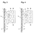
- eine Variante zu
Fig. 1 , mit einem glasierten Keramik-Kollektor, bei einem ersten Einstrahlwinkel (Sonnenstand), - Fig. 4
- die Variante
Fig. 3 , bei erhöhtem Sonnenstand, - Fig. 5
- den Aufbau und dessen Halterung an einem hinterlüfteten Keramik-Kollektor, mit angedeuteten Luftströmungen,
- Fig. 6
- einen flachen, glasierten Keramikkollektor in Verbindung mit streifenförmigen PV-Elementen und
- Fig. 7
- das grundsätzliche Hydraulikschema für die Wärmenutzung im Luftspalt an einer erfindungsgemässen Fassade mit ihrem Luft-Sammelkanal.
- Nachfolgend wird an Hand von teilweise schematischen Zeichnungen der Erfindungsgegenstand näher erläutert. In der Beschreibung und in den Zeichnungen sind gleiche Funktionsteile mit gleichen Ziffern versehen.
- In
Figur 1 ist ein der Solarstrahlung ausgesetztes Modul eines Hybrid-Solarkollektors mit 1 bezeichnet. Frontseitig, in einen Modulrahmen 1' aus Holz eingesetzt befindet sich eine mehrschichtige Abdeckung 2 aus Glas, in der streifenförmige, zueinander beabstandete PV-Elemente 3' eingeschlossen sind. Diese sind miteinander in notorisch bekannter Weise elektrisch verbunden und erzeugen direkt genutzte Gleichspannung (geregelte Batterieladung) oder speisen wahlweise über Wechselrichter Netzgeräte. - Durch die mehrschichtige Abdeckung 2 trifft Infrarotstrahlung auf einen Kollektor 5 aus Massivholz, mit einfallswinkelselektiven Kollektornasen, was - wie beim eingangs genannten Stand der Technik (
WO -A1- 99/54669 - Im Kollektor 5 befinden sich rückseitig Dehnfugen 6, die sowohl der Wärmedehnung als auch zum Feuchtigkeitstransport aus dem Holz dienen. Die anschliessende Dämmung besteht aus einer diffusionsoffenen Trennlage 9, hygroskopischen Platten 10 (Naturfaser verstärkter Lehm), Steinwolle 11 und Gipsplatten 12. Die Dämmung wirkt durch Wärmeleitung grundsätzlich identisch zum erwähnten Stand der Technik. - In überraschender Weise ist diese energetisch gleichwertig, trotz der Abschattung durch die PV-Elemente 3'.- Messungen haben gezeigt, dass sich durch die Abschattung der PV-Elemente 3' der Wärmeeintrag ins Hausinnere in praxi nur um einen U-Wert von 0,09 W/m2·K verschlechtert. Die eingestrahlte Sonnenenergie heizt, auf Grund der Verweilzeit der Strömung A im Luftspalt 4 soweit auf, dass sie, selbst bei bedecktem Himmel, zur Wärmenutzung im Hausinneren ausreicht. - Der Ertrag an Elektroenergie ist jedoch mit konventionellen PV-Elementen relativ bescheiden.
- Als Material für Solarkollektoren aus Holz hat sich insbesondere solches von Lerchen, Eichen aber auch von Tannen und Fichten bewährt.
- Die Nutzung der Warmluft-Strömung A selbst, ist in
Fig. 7 beispielsweise erläutert. - Zur Steigerung des Ertrags an Elektroenergie eignen sich Hochleistungs- PV-Elemente wie sogenannte Bifacial Cells (Neo Solar Power Corporation, 30078 Taiwan). Besonders Effizient sind PV-Elemente der dritten Generation in Heterojunction- Technology ("HAST" eine Kooperation der Meyer Burger Gruppe, Meyer Burger AG, CH-3645 Gwatt mit CSEM SA, CH-2002 Neuchätel) unter Verwendung der Smart Wire Connection Technology "SWCT"; vgl. u.a. Publikation Bundesamt für Energie BFE, CH-3003 Bern, 05/2014. Durch den Einbau und/oder das Aufbringen von Reflektoren auf den Solarkollektor lassen sich diese Hochleistungs- PV-Elemente optimal beidseitig betreiben.
- Aus fabrikatorischen Gründen empfehlen sich kostengünstige Holzkollektoren in zusammengesetzter Ausführung in Verbindung mit Hochleistungs- PV-Elementen. Hierzu werden beispielsweise Profilleisten in Holzplatten eingelassen und frontseitig mit Metallfolien beklebt; hier nicht gezeichnet.
- Noch einfacher herzustellen sind Kollektoren 5 aus Holz gemäss
Fig. 2 , welche in der horizontalen Längsrichtung para-bolische Ausfräsungen 20 aufweisen, die in deren unteren Bereich je mit einer metallischen Folie 21 beklebt sind. Damit wird eine vom Sonnenstand weitgehend unabhängige Rückstrahlung auf die von der Sonnenseite abgewandten bidirektionalen PV-Elemente 3" erzeugt. Die vorhandene Streustrahlung wird als Wärme im oberen Bereich der Ausfräsung 20 erfasst und über Luftauslässe 7' und Abluftrohre 7 abgesogen. Auf Grund der relativ hohen Masse des hier gezeigten Kollektors 5 wurde die Dämmung auf Steinwolle 11 und eine Gipsplatte 12 reduziert. - Während die Hybrid-Solarkollektoren 1a mit Kollektoren 5 aus Holz ausgerüstet sind und sich entsprechend einfach herstellen lassen, erfordern solche nach 1b bis 1e (
Fig. 3 bis Fig. 5 ) aus Keramik aufwändige Fabrikationsmittel. - Keramikkollektoren, lassen sich einstückig mit optimierten Reflektionsnasen 5" im Extrudierverfahren (Strangguss) herstellen. Die Kollektoren 5c (
Fig. 6 ) können frontseitig farbig, vollständig oder partiell glasiert und/oder verspiegelt werden. Diese Art Beschichtung ist mit 21' bezeichnet. Zudem ist deren Wärmekapazität gegenüber Holz etwa doppelt so hoch. Nachteilig ist deren geringe Speicherfähigkeit an Wasser, so dass sich die gewünschte jahreszeitabhängige Wärmeleitung von Holzkollektoren in der Regel nicht einstellt. Ebenfalls ist deren Preis, in Relation zu Kollektoren aus Holz, hoch. Der inFig. 3 und Fig. 4 eingezeichnete Strahlengang, bei unterschiedlichen Einfallswinkeln, zeigt die guten Reflektionseigenschaften der Nasen 5". Dabei sind ν = einfallender Strahl und ν' = reflektierter Strahl. - Keramikkollektoren 5a, 5b und 5c (
Fig. 3-6 ), weisen die von Hohlziegeln (Isolier-Ziegelsteinen) bekannten Hohlräume 50 auf und ergeben entsprechend hohe Isolationswerte, was die Baudicke von Fassaden verringern kann. Aus Übersichtlichkeitsgründen sind inFig. 3-6 die bidirektional wirkenden PV-Elemente 3" nur vereinfacht dargestellt. - Durch geeignete handelsübliche Halterungen 60 (Alphaton® horizontal support profiles; Handelsmarke der Moeding Keramikfassaden GmbH, D-Marklkofen) lassen sich derartige Kollektoren 5b über ihre Schrägflächen 40 leicht montieren und formschlüssig zusammenhalten; siehe
Fig. 5 . - Gemäss
Fig. 6 wird ein flacher, glasierter Keramik-Kollektor 5c über Bohrungen 13, 13' auf seiner Dämmung mittels geeigneter Schrauben 14 befestigt. Die gesamte Frontfläche des Kollektors 5c ist mit einer reflektierenden Glasur 21' versehen. - Die einfallswinkelselektive Wirkung am Kollektor 5c wird hier durch PV-Elemente hoher Opazität erreicht. - Nachteilig bei dieser Variante ist die geringe Hygroskopie des Schichtaufbaus, so dass die erwünschte, jahreszeitlich abhängige Wärmeleitfähigkeit nur minimal ist. Eine gewisse Verbesserung und eine Temperaturerhöhung der Warmluft-Strömung A lässt sich durch Distanzelemente zwischen Kollektor 5c und Dämmung (Steinwolle 11 und Gipsplatte 12) erreichen (nicht gezeichnet), so dass auch hier eine Hinterlüftung mit einer Parallel-Strömung entstehen kann.
- In sämtlichen Ausführungsbeispielen sind nur einzelne Luftauslässe 7,7' gezeichnet. Selbstverständlich muss die Warmluft-Strömung A, auf gleicher Höhe über mehrere Rohre 7, 7' abgesaugt werden. Hierzu dient ein Sammelkanal 8,
Fig. 7 , dessen grosses Abluftrohr 7" an eine Luft-Wasser Wärmepumpe 80 angeschlossen ist. Im Abluftrohr 7" ist ein Temperaturfühler 83 eingesetzt, dessen Signalleitung 84 in einer Steuerung 81 die Drehzahl eines Verdichters steuert, derart dass die Eingangstemperatur in der Wärmepumpe 80 in einem kleinen Temperaturintervall konstant gehalten ist. Die symbolisch dargestellte Wärmepumpe 80 weist eine Frischwasserzufuhr 70 und Brauchwasseranschlüsse 71 bis 73 auf. Zusätzlich führen Anschlüsse 74 und 75 zu einem Wärmetauscher, der in einem temperaturgeschichteten Speicher (Solarspeicher) Warmwasserlieferungen, auch außerhalb der Sonneneinstrahlung gewährleistet. Die in der Wärmepumpe 80 abgekühlte Abluft A' wird über ein vertikales Abluft-Rohr 85 mit Schutzhaube 86 ins Freie abgelassen. - Ist im System elektrische Überschussenergie vorhanden, so kann der Speicher auch über eine eingebaute Widerstandsheizung zusätzlich erwärmt (nachgeheizt) werden, was in solaren Spitzenzeiten einer Energiespeicherung entspricht.
- An Stelle der über einen Verdichter in der Wärmepumpe 80 gesteuerten Luftmenge kann durch Steuerung der Zuluft Z im Luftspalt 4 (
Fig. 1 ,Fig. 2 ) das Volumen der Warmluft-Strömung A auch geregelt werden. Durch eine zusätzliche Frischluftzufuhr lässt sich zudem eine Temperatursteuerung realisieren, die auf die erforderlichen Luftwechsel im Haus abgestimmt ist. Damit kann eine einfache Komfortlüftung und Heizungsunterstützung aufgebaut werden. - Eine Steuerung der Zuluft Z im Luftspalt 4 kann zudem zur forcierten Abkühlung der Solarkollektoren verwendet werden, wenn im Hochsommer extreme Einstrahlungsverhältnisse herrschen. Damit wird der Wirkungsgrad der PV-Elemente erhöht und gleichzeitig mit einfachen Mitteln auch die Wärmeeinleitung ins Hausinnere reduziert und somit der Wohnkomfort gesteigert, dies ohne Einsatz von stromfressenden Kühlgeräten (Aircondition).
- Der Erfindungsgegenstand ist grundsätzlich modular ausgelegt und kann auch nachträglich in bestehenden Bauten, insbesondere in solchen mit einfallswinkelselektiven Sonnenkollektoren nach
WO -A1- 99/54669 -
- 1
- Modul (oberes)
- 1'
- Modulrahmen (Holz)
- 1a
- Hybrid- Solarkollektor (Ausführung in Holz)
- 1b-1e
- Hybrid- Solarkollektoren (Ausführung in Keramik)
- 2
- mehrschichtige Abdeckung (Glas)
- 3'
- PV-Element (einfach)
- 3"
- PV-Element (bidirektional)
- 4
- Luftspalt
- 4'
- Abluft-Lücke
- 5
- Kollektoren aus Holz
- 5b,5c
- Kollektoren aus Keramik
- 5d
- Flachkollektor (aus Keramik)
- 5'
- Reflexionsnasen
- 5"
- Reflexionsnasen verspiegelt /glasiert (Keramik)
- 5c'
- Stege
- 6
- Dehnfugen /Feuchttransport
- 7, 7'
- Luftauslässe
- 7"
- Abluftrohr (gross) von 8
- 8
- Sammelkanal
- 9
- diffusionsoffene Trennlage
- 10
- hygroskopischen Platten (Naturfasern in Lehm)
- 11
- Steinwolle
- 12
- Gipsplatten (Innenraum)
- 13,13'
- Bohrungen) in 5c
- 14
- Befestigungsschraube mit Federscheibe
- 20
- Parabolische Ausfräsungen
- 21
- Metallische Folie
- 21'
- Beschichtung/Glasur (reflektierend) auf 5c
- 40
- Schrägflächen
- 50
- Hohlräume (horizontal)
- 60
- Halterung
- 70
- Frischwasserzufuhr
- 71-73
- Brauchwasseranschlüsse
- 74-75
- Anschlüsse zu Wärmetauscher (in geschichtetem Wasserspeicher)
- 80
- Luft-Wasser Wärmepumpe
- 81
- Steuerung zu 80
- 82-
- Anzeige- und Kontrollpanel (Ruhezustand)
- 83
- Temperaturfühler
- 84
- Signalleitung zu Drehzahlsteuerung Ventilator (Verdichter)
- 85
- Abluft-Rohr
- 86
- Schutzhaube
- A
- Warmluft-Strömung
- A'
- Abluft (kalt)
- Z
- Zuluft
- ν
- Einfallender Strahl
- ν'
- Reflektierter Strahl
Claims (12)
- Hybrid-Solarkollektor für Fassaden bestehend aus einer hinterlüfteten Abdeckung, einem einfallswinkelselektiven thermischen Kollektor mit angeschlossener Dämmung, welcher die aufgenommene Wärme zeitverschoben ins Rauminnere leitet, dadurch gekennzeichnet, dass an der Abdeckung (2) Photovoltaik-Elemente (3,3")angeordnet sind, welche partiell transparent und/oder oder partiell lichtdurchlässig sind und zumindest partiell Infrarotstrahlung durchlassen und dass die zwischen dem Kollektor und der Abdeckung sich bei Sonnenstrahlung erwärmende Luft (A) zumindest im obersten Bereich für Nutzzwecke abgeführt ist.
- Hybrid-Solarkollektor nach Anspruch 1, dadurch gekennzeichnet, dass mindestens ein Kollektor (5,5a,5b,5c) in seinem oberen Bereich eine Abluftlücke (4') und/oder wenigstens ein Abluftrohr (7) aufweist.
- Hybrid-Solarkollektor nach Anspruch 1, dadurch gekennzeichnet, dass der Kollektor (5,5a,5b,5c) wenigstens teilweise aus Massivholz, Keramik oder Lehm besteht.
- Hybrid-Solarkollektor nach Anspruch 1, dadurch gekennzeichnet, dass der Kollektor (5a,5b,5c) aus Keramik besteht und horizontal verlaufende Hohlräume (50) besitzt.
- Hybrid-Solarkollektor nach Anspruch 3, dadurch gekennzeichnet, dass der Kollektor (5a,5b,5c) auf eine gezielte Reflektion der Strahlung (ν')ausgerichtet ist und das hierfür entsprechende Beschichtungen vorgesehen sind.
- Hybrid-Solarkollektor nach Anspruch 5, dadurch gekennzeichnet, dass der Kollektor (5,5b) frontal angeordnete Reflektionsnasen (5',5") aufweist.
- Hybrid-Solarkollektor nach Anspruch 1, dadurch gekennzeichnet, dass die PV-Elemente (3',3") streifenförmig ausgebildet und zueinander beabstandet horizontal ausgerichtet sind.
- Hybrid-Solarkollektor nach Anspruch 1, dadurch gekennzeichnet, dass die PV-Elemente (3") bifacial wirksam und streifenförmig ausgebildet und zueinander beabstandet horizontal ausgerichtet sind.
- Hybrid-Solarkollektor nach Anspruch 1, dadurch gekennzeichnet, dass, die partielle Lichtdurchlässigkeit der PV-Elemente (3') durch eine flächige Struktur gebildet ist, mit Vorderseite und Rückseite, und dass diese miteinander parallel verschaltet sind.
- Verfahren zum Betrieb eines Hybrid-Solarkollektors nach Anspruch 1, dass die Abluft (A) aus den Abluftlücken (4')im oberen Bereich mehrerer Kollektoren (5), in gleicher Höhe, über Abluftrohre (7) in einen Sammelkanal (8) geführt und durchmischt wird und anschliessend zentral zur Nutzung und/oder Aufbereitung ins Hausinnere geführt wird.
- Verfahren zum Betrieb eines Hybrid-Solarkollektors nach Anspruch 1, dass in die Abluftlücke (4') oder den Sammelkanal (8) Frischluft zugeführt wird.
- Verfahren zum Betrieb eines Hybrid-Solarkol·lektors nach Anspruch 1, dass die Temperatur der Abluft (A) gemessen wird und über den Sammelkanal (8) in eine geregelte Wärmepumpe (80) geführt wird, wobei ein in der Wärmepumpe (80) vorhandener drehzahlveränderlicher Verdichter die Abluft (A) über die Luftmenge im Luftspalt (4) der Module (1) derart steuert, dass sich die Temperatur im Abluftrohr (7") auf einem konstanten Sollwert einstellt, so dass die Wärmepumpe (80) in einem optimalen Betriebspunkt arbeitet.
Priority Applications (4)
| Application Number | Priority Date | Filing Date | Title |
|---|---|---|---|
| DK15405053.8T DK3136016T3 (da) | 2015-08-25 | 2015-08-25 | Hybrid-solfanger samt fremgangsmåde til drift af denne |
| EP15405053.8A EP3136016B1 (de) | 2015-08-25 | 2015-08-25 | Hybrid-solarkollektor sowie verfahren zu dessen betrieb |
| US15/245,069 US10177709B2 (en) | 2015-08-25 | 2016-08-23 | Hybrid solar collector and operating procedure |
| CA2940227A CA2940227C (en) | 2015-08-25 | 2016-08-24 | Hybrid solar collector and operating procedure |
Applications Claiming Priority (1)
| Application Number | Priority Date | Filing Date | Title |
|---|---|---|---|
| EP15405053.8A EP3136016B1 (de) | 2015-08-25 | 2015-08-25 | Hybrid-solarkollektor sowie verfahren zu dessen betrieb |
Publications (2)
| Publication Number | Publication Date |
|---|---|
| EP3136016A1 true EP3136016A1 (de) | 2017-03-01 |
| EP3136016B1 EP3136016B1 (de) | 2019-03-13 |
Family
ID=54065832
Family Applications (1)
| Application Number | Title | Priority Date | Filing Date |
|---|---|---|---|
| EP15405053.8A Active EP3136016B1 (de) | 2015-08-25 | 2015-08-25 | Hybrid-solarkollektor sowie verfahren zu dessen betrieb |
Country Status (4)
| Country | Link |
|---|---|
| US (1) | US10177709B2 (de) |
| EP (1) | EP3136016B1 (de) |
| CA (1) | CA2940227C (de) |
| DK (1) | DK3136016T3 (de) |
Cited By (2)
| Publication number | Priority date | Publication date | Assignee | Title |
|---|---|---|---|---|
| US20210407739A1 (en) * | 2020-06-26 | 2021-12-30 | Taka Solar Corporation | Solar cell systems and methods of making the same |
| DE102023135663A1 (de) * | 2023-12-18 | 2025-06-18 | Peter Hulin-Bischof | System zum effizienten Energiehaushalt in einem Gebäude |
Families Citing this family (5)
| Publication number | Priority date | Publication date | Assignee | Title |
|---|---|---|---|---|
| CN107070379A (zh) * | 2017-05-24 | 2017-08-18 | 佛山市森和业丰纸制品有限公司 | 一种隔热光伏瓦 |
| CN107355995B (zh) * | 2017-08-26 | 2023-04-18 | 李春信 | 一种平排孔型太阳能真空集热管太阳灶与集热器 |
| US20220364408A1 (en) * | 2021-05-11 | 2022-11-17 | Oren Aharon | Climate adaptive glass envelope for building |
| NL2031116B1 (nl) | 2022-03-01 | 2023-09-07 | Jan Putman Beheer B V | Zonnepaneel ingericht voor geforceerde ventilatie, klimaatsysteem voor een gebouw, voorzien van een dergelijk zonnepaneel en werkwijze voor het opwekken van energie en/of het beheersen van het klimaat in een gebouw gebruik makend van een dergelijk zonnepaneel |
| GB2622876A (en) * | 2022-09-30 | 2024-04-03 | Water Filled Glass Ltd | A method of installing a heat transfer panel |
Citations (5)
| Publication number | Priority date | Publication date | Assignee | Title |
|---|---|---|---|---|
| WO1999054669A1 (de) | 1998-04-20 | 1999-10-28 | Giuseppe Fent Architekturbüro | Solarzelle mit sonnenkollektor und speicherelementen |
| DE19914079A1 (de) * | 1999-03-27 | 2000-09-28 | Abac Elektronische Kommunikati | Photovoltaik-Modul |
| US20110232724A1 (en) * | 2008-10-02 | 2011-09-29 | Suez Environnement | Device for producing energy from solar radiation |
| FR2978298A1 (fr) * | 2011-07-19 | 2013-01-25 | Suez Environnement | Module de production d'energie photovoltaique et thermique a partir du rayonnement solaire, et installation equipee de tels modules. |
| WO2015091698A1 (de) | 2013-12-20 | 2015-06-25 | Fraunhofer-Gesellschaft zur Förderung der angewandten Forschung e.V. | Photovoltaische zelle, photovoltaikmodul sowie dessen herstellung und verwendung |
Family Cites Families (3)
| Publication number | Priority date | Publication date | Assignee | Title |
|---|---|---|---|---|
| WO2006128236A1 (en) * | 2005-05-31 | 2006-12-07 | Roger A Farquhar | Solar earth module |
| ES2304211B1 (es) * | 2007-02-01 | 2009-05-22 | Manuel Lahuerta Romeo | Seguidor solar de paneles termicos y fotovoltaicos con sistema impulsor de aire aplicable a edificios. |
| FR2955705B1 (fr) | 2010-01-27 | 2012-07-27 | Suez Environnement | Module de production d'energie mixte photovoltaique et thermique a partir du rayonnement solaire, et installation equipee de tels modules |
-
2015
- 2015-08-25 DK DK15405053.8T patent/DK3136016T3/da active
- 2015-08-25 EP EP15405053.8A patent/EP3136016B1/de active Active
-
2016
- 2016-08-23 US US15/245,069 patent/US10177709B2/en active Active
- 2016-08-24 CA CA2940227A patent/CA2940227C/en active Active
Patent Citations (5)
| Publication number | Priority date | Publication date | Assignee | Title |
|---|---|---|---|---|
| WO1999054669A1 (de) | 1998-04-20 | 1999-10-28 | Giuseppe Fent Architekturbüro | Solarzelle mit sonnenkollektor und speicherelementen |
| DE19914079A1 (de) * | 1999-03-27 | 2000-09-28 | Abac Elektronische Kommunikati | Photovoltaik-Modul |
| US20110232724A1 (en) * | 2008-10-02 | 2011-09-29 | Suez Environnement | Device for producing energy from solar radiation |
| FR2978298A1 (fr) * | 2011-07-19 | 2013-01-25 | Suez Environnement | Module de production d'energie photovoltaique et thermique a partir du rayonnement solaire, et installation equipee de tels modules. |
| WO2015091698A1 (de) | 2013-12-20 | 2015-06-25 | Fraunhofer-Gesellschaft zur Förderung der angewandten Forschung e.V. | Photovoltaische zelle, photovoltaikmodul sowie dessen herstellung und verwendung |
Cited By (7)
| Publication number | Priority date | Publication date | Assignee | Title |
|---|---|---|---|---|
| US20210407739A1 (en) * | 2020-06-26 | 2021-12-30 | Taka Solar Corporation | Solar cell systems and methods of making the same |
| US20210408316A1 (en) * | 2020-06-26 | 2021-12-30 | Taka Solar Corporation | Solar cell systems and methods of making the same |
| US11495414B2 (en) * | 2020-06-26 | 2022-11-08 | Taka Solar Corporation | Solar cell systems and methods of making the same |
| US11495415B2 (en) * | 2020-06-26 | 2022-11-08 | Taka Solar Corporation | Solar cell systems and methods of making the same |
| US20230402234A1 (en) * | 2020-06-26 | 2023-12-14 | Taka Solar Corporation | Solar cell systems and methods of making the same |
| US12382730B2 (en) * | 2020-06-26 | 2025-08-05 | Taka Solar Corporation | Solar cell systems and methods of making the same |
| DE102023135663A1 (de) * | 2023-12-18 | 2025-06-18 | Peter Hulin-Bischof | System zum effizienten Energiehaushalt in einem Gebäude |
Also Published As
| Publication number | Publication date |
|---|---|
| DK3136016T3 (da) | 2019-05-13 |
| US20170063302A1 (en) | 2017-03-02 |
| CA2940227A1 (en) | 2017-02-25 |
| CA2940227C (en) | 2023-12-12 |
| EP3136016B1 (de) | 2019-03-13 |
| US10177709B2 (en) | 2019-01-08 |
Similar Documents
| Publication | Publication Date | Title |
|---|---|---|
| EP3136016B1 (de) | Hybrid-solarkollektor sowie verfahren zu dessen betrieb | |
| DE19902650A1 (de) | Verfahren zur Gewinnung von Solarenergie durch kombinierte Umwandlung in elektrische und thermische Energie und deren Verwertung sowie Vorrichtungen zur Durchführung des Verfahrens | |
| DE10144148A1 (de) | Solarenergieanlage für ein Gebäude, insbesondere ein Wohnhaus | |
| EP2174068A1 (de) | Dachaufbau für ein solarsystem | |
| DE10102918A1 (de) | Photovoltaisch und solarthermisch wirksame Verbundpaneele und deren Anwendung | |
| AT510391A2 (de) | Aktivfassade | |
| CN107246225A (zh) | 可发电调光隔热通风遮阳的装置 | |
| EP2230362A2 (de) | Abdeckelement | |
| EP1703063B1 (de) | Fensterprofil mit Solar-Element | |
| DE19716418C2 (de) | Einrichtung zur solaren Nutzwärmeerzeugung und Klimatisierung für Glasdachkonstruktionen | |
| EP0005499B1 (de) | Fenster mit Sonnenkollektor | |
| DE4322653C2 (de) | Brüstungselement | |
| DE102008062286A1 (de) | Solarmodul | |
| EP1978183A2 (de) | Energiesparhaus | |
| DE102007052407A1 (de) | Fassadensystem zur Verkleidung eines Bauwerks | |
| DE102012104528A1 (de) | Profilsystem zur Befestigung von flexiblen Paneels | |
| EP3935318B1 (de) | Temperierungssystem | |
| DE19544245A1 (de) | Bauwerk | |
| DE2801714A1 (de) | Anlage zur sonnenenergiegewinnung mit hilfe einer reflektierenden lamellenartigen vorhangwand als konzentrationssystem | |
| WO1999042766A1 (de) | Anordnung zum aufnehmen von solarenergie an gebäuden | |
| WO2019180470A1 (en) | Hot air facade mounted solar panel | |
| DE102023135663A1 (de) | System zum effizienten Energiehaushalt in einem Gebäude | |
| DE10115035C2 (de) | Niedrigenergiegebäude, insbesondere einergie-Autarkes Gebäude | |
| CH708493B1 (de) | Thermoaktives Gebäudehüllensystem. | |
| DE202017000575U1 (de) | Solar-keramische Außenfassade |
Legal Events
| Date | Code | Title | Description |
|---|---|---|---|
| PUAI | Public reference made under article 153(3) epc to a published international application that has entered the european phase |
Free format text: ORIGINAL CODE: 0009012 |
|
| STAA | Information on the status of an ep patent application or granted ep patent |
Free format text: STATUS: THE APPLICATION HAS BEEN PUBLISHED |
|
| AK | Designated contracting states |
Kind code of ref document: A1 Designated state(s): AL AT BE BG CH CY CZ DE DK EE ES FI FR GB GR HR HU IE IS IT LI LT LU LV MC MK MT NL NO PL PT RO RS SE SI SK SM TR |
|
| AX | Request for extension of the european patent |
Extension state: BA ME |
|
| STAA | Information on the status of an ep patent application or granted ep patent |
Free format text: STATUS: REQUEST FOR EXAMINATION WAS MADE |
|
| 17P | Request for examination filed |
Effective date: 20170614 |
|
| REG | Reference to a national code |
Ref country code: DE Ref legal event code: R079 Ref document number: 502015008316 Country of ref document: DE Free format text: PREVIOUS MAIN CLASS: F24J0002040000 Ipc: F24S0010000000 |
|
| GRAP | Despatch of communication of intention to grant a patent |
Free format text: ORIGINAL CODE: EPIDOSNIGR1 |
|
| STAA | Information on the status of an ep patent application or granted ep patent |
Free format text: STATUS: GRANT OF PATENT IS INTENDED |
|
| RIC1 | Information provided on ipc code assigned before grant |
Ipc: F24S 10/00 20170301AFI20181024BHEP |
|
| INTG | Intention to grant announced |
Effective date: 20181205 |
|
| RIC1 | Information provided on ipc code assigned before grant |
Ipc: F24S 10/00 20180101AFI20181024BHEP |
|
| GRAS | Grant fee paid |
Free format text: ORIGINAL CODE: EPIDOSNIGR3 |
|
| GRAA | (expected) grant |
Free format text: ORIGINAL CODE: 0009210 |
|
| STAA | Information on the status of an ep patent application or granted ep patent |
Free format text: STATUS: THE PATENT HAS BEEN GRANTED |
|
| RIC1 | Information provided on ipc code assigned before grant |
Ipc: F24S 10/00 20180101AFI20181024BHEP |
|
| AK | Designated contracting states |
Kind code of ref document: B1 Designated state(s): AL AT BE BG CH CY CZ DE DK EE ES FI FR GB GR HR HU IE IS IT LI LT LU LV MC MK MT NL NO PL PT RO RS SE SI SK SM TR |
|
| REG | Reference to a national code |
Ref country code: GB Ref legal event code: FG4D Free format text: NOT ENGLISH |
|
| REG | Reference to a national code |
Ref country code: CH Ref legal event code: EP Ref country code: AT Ref legal event code: REF Ref document number: 1108260 Country of ref document: AT Kind code of ref document: T Effective date: 20190315 |
|
| REG | Reference to a national code |
Ref country code: IE Ref legal event code: FG4D Free format text: LANGUAGE OF EP DOCUMENT: GERMAN |
|
| REG | Reference to a national code |
Ref country code: DE Ref legal event code: R096 Ref document number: 502015008316 Country of ref document: DE |
|
| REG | Reference to a national code |
Ref country code: DK Ref legal event code: T3 Effective date: 20190508 |
|
| REG | Reference to a national code |
Ref country code: CH Ref legal event code: NV Representative=s name: PPS POLYVALENT PATENT SERVICE AG, CH |
|
| REG | Reference to a national code |
Ref country code: SE Ref legal event code: TRGR |
|
| REG | Reference to a national code |
Ref country code: NL Ref legal event code: FP |
|
| REG | Reference to a national code |
Ref country code: NO Ref legal event code: T2 Effective date: 20190313 |
|
| REG | Reference to a national code |
Ref country code: LT Ref legal event code: MG4D |
|
| PG25 | Lapsed in a contracting state [announced via postgrant information from national office to epo] |
Ref country code: FI Free format text: LAPSE BECAUSE OF FAILURE TO SUBMIT A TRANSLATION OF THE DESCRIPTION OR TO PAY THE FEE WITHIN THE PRESCRIBED TIME-LIMIT Effective date: 20190313 Ref country code: LT Free format text: LAPSE BECAUSE OF FAILURE TO SUBMIT A TRANSLATION OF THE DESCRIPTION OR TO PAY THE FEE WITHIN THE PRESCRIBED TIME-LIMIT Effective date: 20190313 |
|
| PG25 | Lapsed in a contracting state [announced via postgrant information from national office to epo] |
Ref country code: RS Free format text: LAPSE BECAUSE OF FAILURE TO SUBMIT A TRANSLATION OF THE DESCRIPTION OR TO PAY THE FEE WITHIN THE PRESCRIBED TIME-LIMIT Effective date: 20190313 Ref country code: BG Free format text: LAPSE BECAUSE OF FAILURE TO SUBMIT A TRANSLATION OF THE DESCRIPTION OR TO PAY THE FEE WITHIN THE PRESCRIBED TIME-LIMIT Effective date: 20190613 Ref country code: HR Free format text: LAPSE BECAUSE OF FAILURE TO SUBMIT A TRANSLATION OF THE DESCRIPTION OR TO PAY THE FEE WITHIN THE PRESCRIBED TIME-LIMIT Effective date: 20190313 Ref country code: GR Free format text: LAPSE BECAUSE OF FAILURE TO SUBMIT A TRANSLATION OF THE DESCRIPTION OR TO PAY THE FEE WITHIN THE PRESCRIBED TIME-LIMIT Effective date: 20190614 Ref country code: LV Free format text: LAPSE BECAUSE OF FAILURE TO SUBMIT A TRANSLATION OF THE DESCRIPTION OR TO PAY THE FEE WITHIN THE PRESCRIBED TIME-LIMIT Effective date: 20190313 |
|
| PG25 | Lapsed in a contracting state [announced via postgrant information from national office to epo] |
Ref country code: EE Free format text: LAPSE BECAUSE OF FAILURE TO SUBMIT A TRANSLATION OF THE DESCRIPTION OR TO PAY THE FEE WITHIN THE PRESCRIBED TIME-LIMIT Effective date: 20190313 Ref country code: AL Free format text: LAPSE BECAUSE OF FAILURE TO SUBMIT A TRANSLATION OF THE DESCRIPTION OR TO PAY THE FEE WITHIN THE PRESCRIBED TIME-LIMIT Effective date: 20190313 Ref country code: PT Free format text: LAPSE BECAUSE OF FAILURE TO SUBMIT A TRANSLATION OF THE DESCRIPTION OR TO PAY THE FEE WITHIN THE PRESCRIBED TIME-LIMIT Effective date: 20190713 Ref country code: RO Free format text: LAPSE BECAUSE OF FAILURE TO SUBMIT A TRANSLATION OF THE DESCRIPTION OR TO PAY THE FEE WITHIN THE PRESCRIBED TIME-LIMIT Effective date: 20190313 Ref country code: CZ Free format text: LAPSE BECAUSE OF FAILURE TO SUBMIT A TRANSLATION OF THE DESCRIPTION OR TO PAY THE FEE WITHIN THE PRESCRIBED TIME-LIMIT Effective date: 20190313 Ref country code: SK Free format text: LAPSE BECAUSE OF FAILURE TO SUBMIT A TRANSLATION OF THE DESCRIPTION OR TO PAY THE FEE WITHIN THE PRESCRIBED TIME-LIMIT Effective date: 20190313 Ref country code: ES Free format text: LAPSE BECAUSE OF FAILURE TO SUBMIT A TRANSLATION OF THE DESCRIPTION OR TO PAY THE FEE WITHIN THE PRESCRIBED TIME-LIMIT Effective date: 20190313 |
|
| PG25 | Lapsed in a contracting state [announced via postgrant information from national office to epo] |
Ref country code: SM Free format text: LAPSE BECAUSE OF FAILURE TO SUBMIT A TRANSLATION OF THE DESCRIPTION OR TO PAY THE FEE WITHIN THE PRESCRIBED TIME-LIMIT Effective date: 20190313 Ref country code: PL Free format text: LAPSE BECAUSE OF FAILURE TO SUBMIT A TRANSLATION OF THE DESCRIPTION OR TO PAY THE FEE WITHIN THE PRESCRIBED TIME-LIMIT Effective date: 20190313 |
|
| REG | Reference to a national code |
Ref country code: DE Ref legal event code: R097 Ref document number: 502015008316 Country of ref document: DE |
|
| PG25 | Lapsed in a contracting state [announced via postgrant information from national office to epo] |
Ref country code: IS Free format text: LAPSE BECAUSE OF FAILURE TO SUBMIT A TRANSLATION OF THE DESCRIPTION OR TO PAY THE FEE WITHIN THE PRESCRIBED TIME-LIMIT Effective date: 20190713 |
|
| PLBE | No opposition filed within time limit |
Free format text: ORIGINAL CODE: 0009261 |
|
| STAA | Information on the status of an ep patent application or granted ep patent |
Free format text: STATUS: NO OPPOSITION FILED WITHIN TIME LIMIT |
|
| 26N | No opposition filed |
Effective date: 20191216 |
|
| PG25 | Lapsed in a contracting state [announced via postgrant information from national office to epo] |
Ref country code: SI Free format text: LAPSE BECAUSE OF FAILURE TO SUBMIT A TRANSLATION OF THE DESCRIPTION OR TO PAY THE FEE WITHIN THE PRESCRIBED TIME-LIMIT Effective date: 20190313 |
|
| REG | Reference to a national code |
Ref country code: DE Ref legal event code: R082 Ref document number: 502015008316 Country of ref document: DE |
|
| PG25 | Lapsed in a contracting state [announced via postgrant information from national office to epo] |
Ref country code: TR Free format text: LAPSE BECAUSE OF FAILURE TO SUBMIT A TRANSLATION OF THE DESCRIPTION OR TO PAY THE FEE WITHIN THE PRESCRIBED TIME-LIMIT Effective date: 20190313 |
|
| PG25 | Lapsed in a contracting state [announced via postgrant information from national office to epo] |
Ref country code: MC Free format text: LAPSE BECAUSE OF FAILURE TO SUBMIT A TRANSLATION OF THE DESCRIPTION OR TO PAY THE FEE WITHIN THE PRESCRIBED TIME-LIMIT Effective date: 20190313 |
|
| PG25 | Lapsed in a contracting state [announced via postgrant information from national office to epo] |
Ref country code: IE Free format text: LAPSE BECAUSE OF NON-PAYMENT OF DUE FEES Effective date: 20190825 |
|
| PGFP | Annual fee paid to national office [announced via postgrant information from national office to epo] |
Ref country code: NL Payment date: 20200826 Year of fee payment: 6 |
|
| PGFP | Annual fee paid to national office [announced via postgrant information from national office to epo] |
Ref country code: LU Payment date: 20200820 Year of fee payment: 6 Ref country code: DK Payment date: 20200820 Year of fee payment: 6 Ref country code: NO Payment date: 20200825 Year of fee payment: 6 Ref country code: GB Payment date: 20200826 Year of fee payment: 6 |
|
| PGFP | Annual fee paid to national office [announced via postgrant information from national office to epo] |
Ref country code: SE Payment date: 20200826 Year of fee payment: 6 Ref country code: BE Payment date: 20200825 Year of fee payment: 6 Ref country code: IT Payment date: 20200831 Year of fee payment: 6 |
|
| PG25 | Lapsed in a contracting state [announced via postgrant information from national office to epo] |
Ref country code: CY Free format text: LAPSE BECAUSE OF FAILURE TO SUBMIT A TRANSLATION OF THE DESCRIPTION OR TO PAY THE FEE WITHIN THE PRESCRIBED TIME-LIMIT Effective date: 20190313 |
|
| PG25 | Lapsed in a contracting state [announced via postgrant information from national office to epo] |
Ref country code: HU Free format text: LAPSE BECAUSE OF FAILURE TO SUBMIT A TRANSLATION OF THE DESCRIPTION OR TO PAY THE FEE WITHIN THE PRESCRIBED TIME-LIMIT; INVALID AB INITIO Effective date: 20150825 Ref country code: MT Free format text: LAPSE BECAUSE OF FAILURE TO SUBMIT A TRANSLATION OF THE DESCRIPTION OR TO PAY THE FEE WITHIN THE PRESCRIBED TIME-LIMIT Effective date: 20190313 |
|
| REG | Reference to a national code |
Ref country code: DK Ref legal event code: EBP Effective date: 20210831 |
|
| REG | Reference to a national code |
Ref country code: NO Ref legal event code: MMEP |
|
| REG | Reference to a national code |
Ref country code: SE Ref legal event code: EUG |
|
| REG | Reference to a national code |
Ref country code: NL Ref legal event code: MM Effective date: 20210901 |
|
| REG | Reference to a national code |
Ref country code: BE Ref legal event code: MM Effective date: 20210831 |
|
| GBPC | Gb: european patent ceased through non-payment of renewal fee |
Effective date: 20210825 |
|
| PG25 | Lapsed in a contracting state [announced via postgrant information from national office to epo] |
Ref country code: SE Free format text: LAPSE BECAUSE OF NON-PAYMENT OF DUE FEES Effective date: 20210826 Ref country code: NO Free format text: LAPSE BECAUSE OF NON-PAYMENT OF DUE FEES Effective date: 20210831 Ref country code: LU Free format text: LAPSE BECAUSE OF NON-PAYMENT OF DUE FEES Effective date: 20210825 |
|
| PG25 | Lapsed in a contracting state [announced via postgrant information from national office to epo] |
Ref country code: NL Free format text: LAPSE BECAUSE OF NON-PAYMENT OF DUE FEES Effective date: 20210901 Ref country code: MK Free format text: LAPSE BECAUSE OF FAILURE TO SUBMIT A TRANSLATION OF THE DESCRIPTION OR TO PAY THE FEE WITHIN THE PRESCRIBED TIME-LIMIT Effective date: 20190313 |
|
| PG25 | Lapsed in a contracting state [announced via postgrant information from national office to epo] |
Ref country code: IT Free format text: LAPSE BECAUSE OF NON-PAYMENT OF DUE FEES Effective date: 20210825 Ref country code: GB Free format text: LAPSE BECAUSE OF NON-PAYMENT OF DUE FEES Effective date: 20210825 Ref country code: DK Free format text: LAPSE BECAUSE OF NON-PAYMENT OF DUE FEES Effective date: 20210831 Ref country code: BE Free format text: LAPSE BECAUSE OF NON-PAYMENT OF DUE FEES Effective date: 20210831 |
|
| REG | Reference to a national code |
Ref country code: FR Ref legal event code: PLFP Year of fee payment: 8 |
|
| PGFP | Annual fee paid to national office [announced via postgrant information from national office to epo] |
Ref country code: DE Payment date: 20250828 Year of fee payment: 11 |
|
| PGFP | Annual fee paid to national office [announced via postgrant information from national office to epo] |
Ref country code: FR Payment date: 20250826 Year of fee payment: 11 Ref country code: AT Payment date: 20250822 Year of fee payment: 11 |
|
| PGFP | Annual fee paid to national office [announced via postgrant information from national office to epo] |
Ref country code: CH Payment date: 20250901 Year of fee payment: 11 |