EP3135838B1 - Mechanical locking system for floor panels - Google Patents
Mechanical locking system for floor panels Download PDFInfo
- Publication number
- EP3135838B1 EP3135838B1 EP16184205.9A EP16184205A EP3135838B1 EP 3135838 B1 EP3135838 B1 EP 3135838B1 EP 16184205 A EP16184205 A EP 16184205A EP 3135838 B1 EP3135838 B1 EP 3135838B1
- Authority
- EP
- European Patent Office
- Prior art keywords
- tongue
- locking
- groove
- building
- panel
- Prior art date
- Legal status (The legal status is an assumption and is not a legal conclusion. Google has not performed a legal analysis and makes no representation as to the accuracy of the status listed.)
- Active
Links
Images


Classifications
-
- E—FIXED CONSTRUCTIONS
- E04—BUILDING
- E04F—FINISHING WORK ON BUILDINGS, e.g. STAIRS, FLOORS
- E04F15/00—Flooring
- E04F15/02—Flooring or floor layers composed of a number of similar elements
-
- E—FIXED CONSTRUCTIONS
- E04—BUILDING
- E04F—FINISHING WORK ON BUILDINGS, e.g. STAIRS, FLOORS
- E04F15/00—Flooring
- E04F15/02—Flooring or floor layers composed of a number of similar elements
- E04F15/02038—Flooring or floor layers composed of a number of similar elements characterised by tongue and groove connections between neighbouring flooring elements
-
- E—FIXED CONSTRUCTIONS
- E04—BUILDING
- E04F—FINISHING WORK ON BUILDINGS, e.g. STAIRS, FLOORS
- E04F2201/00—Joining sheets or plates or panels
- E04F2201/01—Joining sheets, plates or panels with edges in abutting relationship
- E04F2201/0138—Joining sheets, plates or panels with edges in abutting relationship by moving the sheets, plates or panels perpendicular to the main plane
-
- E—FIXED CONSTRUCTIONS
- E04—BUILDING
- E04F—FINISHING WORK ON BUILDINGS, e.g. STAIRS, FLOORS
- E04F2201/00—Joining sheets or plates or panels
- E04F2201/05—Separate connectors or inserts, e.g. pegs, pins, keys or strips
- E04F2201/0523—Separate tongues; Interlocking keys, e.g. joining mouldings of circular, square or rectangular shape
- E04F2201/0547—Separate tongues; Interlocking keys, e.g. joining mouldings of circular, square or rectangular shape adapted to be moved perpendicular to the joint edge
-
- E—FIXED CONSTRUCTIONS
- E04—BUILDING
- E04F—FINISHING WORK ON BUILDINGS, e.g. STAIRS, FLOORS
- E04F2201/00—Joining sheets or plates or panels
- E04F2201/05—Separate connectors or inserts, e.g. pegs, pins, keys or strips
- E04F2201/0523—Separate tongues; Interlocking keys, e.g. joining mouldings of circular, square or rectangular shape
- E04F2201/0564—Separate tongues; Interlocking keys, e.g. joining mouldings of circular, square or rectangular shape depending on the use of specific materials
- E04F2201/0582—Separate tongues; Interlocking keys, e.g. joining mouldings of circular, square or rectangular shape depending on the use of specific materials of fibres or chips, e.g. bonded with synthetic resins
Definitions
- the disclosure generally relates to the field of mechanical locking systems for floor panels and building panels.
- the disclosure shows floorboards, locking systems, installation methods and production methods.
- the present invention is particularly suitable for use in floating floors, which are formed of floor panels which are joined mechanically with a locking system integrated with the floor panel, i.e. mounted at the factory, are made up of one or more upper layers of veneer, decorative laminate powder based surfaces or decorative plastic material, an intermediate core of wood-fibre-based material or plastic material and preferably a lower balancing layer on the rear side of the core.
- the long and short edges are mainly used to simplify the description of the invention.
- the panels may be square.
- the invention is preferably used on the short edges. It should be emphasised that the invention may be used in any floor panel and it may be combined with all types of known locking system formed on the long edges, where the floor panels are intended to be joined using a mechanical locking system connecting the panels in the horizontal and vertical directions on at least two adjacent sides.
- the invention may also be applicable to, for instance, solid wooden floors, parquet floors with a core of wood or wood-fibre-based material and a surface of wood or wood veneer and the like, floors with a printed and preferably also varnished surface, floors with a surface layer of plastic or cork, linoleum, rubber. Even floors with hard surfaces such as stone, tile and similar materials are included and floorings with soft wear layer, for instance needle felt glued to a board.
- the invention may also be used for joining building panels which preferably contain a board material for instance wall panels, ceilings, furniture components and similar.
- Laminate flooring usually comprises a core of a 6-12 mm fibre board, a 0.2-0.8 mm thick upper decorative surface layer of laminate and a 0.1-0.6 mm thick lower balancing layer of laminate, plastic, paper or like material.
- a laminate surface comprises of melamine-impregnated paper.
- the most common core material is fibreboard with high density and good stability usually called HDF - High Density Fibreboard. Sometimes also MDF - Medium Density Fibreboard - is used as core.
- the visible surface of the installed floor panel is called “front side”, while the opposite side of the floor panel, facing the sub floor, is called “rear side”.
- the edge between the front and rear side is called “joint edge”.
- horizontal plane is meant a plane, which extends parallel to the outer part of the surface layer.
- Immediately juxtaposed upper parts of two adjacent joint edges of two joined floor panels together define a “vertical plane” perpendicular to the horizontal plane.
- vertical locking is meant locking parallel to the vertical plane in D1 direction.
- horizontal locking is meant locking parallel to the horizontal plane in D2 direction.
- up is meant towards the front side, by “down” towards the rear side, by “inwardly” mainly horizontally towards an inner and centre part of the panel and by “outwardly” mainly horizontally away from the centre part of the panel.
- locking systems co acting connecting elements, which connect the floor panels vertically and/or horizontally.
- the long edges are installed by angling.
- the panel is than displaced in locked position along the long side.
- the short edges are locked by horizontal snapping.
- the vertical connection is generally a tongue and a groove.
- a strip with a locking element is bent and when the edges are in contact, the strip springs back and a locking element enters a locking groove and locks the panels horizontally.
- Such a snap connection is complicated since a hammer and a tapping block may need to be used to overcome the friction between the long edges and to bend the strip during the snapping action.
- Similar locking systems may also be produced with a rigid strip and they are connected with an angling-angling method where both short and long edges are angled into a locked position.
- EP 2 270 291 A1 discloses a device having a core made of wooden material or wooden material-plastic mixture in a direction perpendicular to a visible side.
- a groove is provided in a recess opened to a lower side and opened in a direction of the recess.
- An upwardly aligned projection has another recess lying opposite to the groove.
- a spring element e.g. a ring, is arranged in the latter recess and deformed in a direction parallel to the visible side in a compressed and/or deformable manner. The spring element is inserted into a structural panel.
- EP 2 034 106 A1 discloses a device that has structural panels with upper and lower sides and profiles provided at side edges.
- a locking element with a locking projection is provided in the profile.
- the element cooperates with a locking recess provided in the profile such that the panels are automatically locked in a vertical direction during a joining movement.
- the locking element is rigidly formed and the locking projection is brought into the recess by a rotary motion of the element that is made of metal or timber material-plastic mixture, e.g. high or medium density fibre board.
- WO 2011/012104 A2 discloses a covering comprising panels that can be connected to each other mechanically.
- the covering has adjacent first and second panels, each having a groove on the sides thereof that are complementary to each other.
- the grooves each have upper and lower groove sides having different lengths and in one of the grooves a spring is arranged that can be moved relative to the panel at least in parts.
- the spring is suitable for engaging in the corresponding groove of the adjacent panel when the adjacent panels are connected, and the spring has at least one projection which points in the direction of the area of the longer groove sides of the other groove that protrudes relative to the shorter groove sides.
- the projection is intended to be moved transversely to the laying plane of the panels in the event of contact with the area of the groove side, wherein the projection is operatively connected to a locking section of the spring.
- the locking section can be moved in the direction of the groove of the adjacent panel as a result of the motion of the projection.
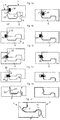
- FIG. 1a, 1b show a flexible tongue 30 with a flexible snap tab extending from the edge.
- Figure 1c, 1d show a displaceable tongue with an inner flexible part that is bendable horizontally in a cross section of the tongue or along the joint.
- Such systems are referred to as vertical snap systems and they provide an automatica locking during the folding action.
- the locking system may also be locked with a side push action such that a displaceable tongue 30 is pushed into a locked position from the long side edge when adjacent sort side edges are folded down to the sub floor.
- a side push action could be difficult to combine with a simple angling and the friction may be too strong for wide panels.
- Figure 1e shows a fold down system with a flexible tongue 30 that is made in one piece with the core.
- Figure 1 f shows a long edge locking system in a fold down system that is connected with angling.
- An overall objective of embodiments of the present invention is to provide a locking system for primarily rectangular floor panels with long and short edges installed in parallel rows, which allows that the short edges may be locked to each other automatically without a snap action that creates a locking resistance and separation forces of the short edges during folding.
- a specific objective is to provide a locking system with a separate displaceable tongue on the fold panel that may lock without any contact with the sharp upper edge of the strip panel and that the tongue is displaced essentially in one direction only from an inner part of a groove and outwardly.
- a first aspect of the invention are building panels provided with a locking system for vertical locking of a first and a second building panel by a vertical displacement of the panels relative each other.
- a sidewardly open tongue groove is provided at an edge of the first building panel.
- a strip protrudes below the tongue groove and outwardly beyond the upper part of the edge of said first panel.
- a displaceable tongue is provided in a sidewardly open displacement groove at an edge of the second building panel.
- the displaceable tongue comprises a main body extending along the edge of the second panel and preferably a tongue locking surface, located at an upper and outer part of the displaceable tongue, configured to cooperate with a groove locking surface of the tongue groove for a vertical locking of the first and the second building panel.
- the displaceable tongue comprises an inner part, spaced inwardly from an upper part of an edge of said second panel, the inner part comprises a tongue pressing surface configured to cooperate with a strip pressing surface on the strip.
- the displaceable tongue is configured to be displaced into the tongue groove when the tongue and the strip pressing surface are displaced vertically against each other to obtain the vertical locking.
- the displaceable tongue is preferably an injection-moulded tongue.
- the displaceable tongue may be asymmetric and comprises a protrusion and the second panel comprises a cavity for housing the protrusion.
- the protrusion may comprise a flexible part.
- the strip is provided with a locking element that cooperates with a downwardly open locking groove formed on the second panel for locking the first and the second building panel in a horizontal direction.
- the tongue pressing surface is preferably positioned on the protrusion and the strip pressing surface is preferably located on the locking element.
- the strip pressing surface is most preferably located on an inclined surface of the locking element that is directed towards the edge of the first building panel.
- the locking system may comprise a cavity that extends from the displacement groove to the locking groove.
- the strip and the tongue pressing surfaces may be inclined against a horizontal plane with an angle of about 25 to 75 degrees.
- the displacement groove may be inclined and comprise an inner part that extends downwards.
- the building panels may be locked vertically by two pairs of cooperating surfaces comprising the groove locking surface and the tongue locking surface, and an upper part of the strip and a lower part of the edge of the second panel, respectively.
- the groove locking surface and the tongue locking surface may be inclined against a horizontal plane.
- the groove locking surface and the tongue locking surface may be inclined with an angle of about 10 to 60 degrees to a horizontal plane.
- the displaceable tongue may be provided with a flexible friction element.
- the displaceable tongue may comprise at least two protrusions extending from the main tongue body and each protrusion may comprise said tongue pressing surface located at an outer part of the protrusion that during locking is in contact with a locking element provided on the strip.
- the building panel may be a floor panel.
- the outer part of the displaceable tongue is in an unlocked position located in the displacement groove.
- the displacement groove may extend vertically above the locking groove.
- the locking groove may be located vertically below the upper part of the displacement groove.
- An upper part of the locking element may be located vertically below the tongue locking surface of the displaceable tongue.
- An upper part of the locking groove may be located vertically below the tongue locking surface of the displaceable tongue.
- the innermost part of the displaceable tongue may be below the outermost part of such tongue.
- the tongue pressing surface may be located vertically below the tongue locking surface.
- An upper part of the locking element may be located in the lower half of an intermediate core of the first building panel.
- the strip may be flexible such that it bends downwards during locking.
- the cavity may be larger than the protrusion such that there is a space S of at least about 1-3 mm.
- the displaceable tongue may be gradually inserted into the tongue groove from a tongue part, which is adjacent an installed long edge, to another tongue part adjacent a free long edge.
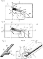
- Figures 2a -2d show a first preferred embodiment of a short edge locking system provided with a flexible and displaceable tongue 30 in an edge of a second panel 1' inserted in a displacement groove 40 and extending along the edge of the second panel.
- the displaceable tongue 30 has a tongue locking surface 31 located at an upper and outer part that cooperates with a groove locking surface 21 located at an inner and upper part of a tongue groove 20 formed in an adjacent edge of a first panel 1.
- the locking surfaces lock the panels in a first vertical direction.
- the locking surfaces are preferably inclined with an angle A2 that is about 10 - 60 degrees.
- the displacement groove is preferably also inclined and the outer part is closer to the panel surface than an inner part.
- the first panel 1 comprises a protruding strip 6 that extends outwardly beyond a vertical plane VP.
- the strip comprises a locking element 8.
- the second panel 1' comprises a locking groove 14 that cooperates with the locking element 8 and locks the panels in a horizontal direction.
- the strip 6 has an upper part 6', which is in contact with a lower part 37 of the adjacent edge and locks the panels in a second vertical direction.
- the displaceable tongue 30 comprises a protrusion 34 extending from a main tongue body 36.
- the second panel 1' comprises at least one cavity 35 for housing the protrusion.
- the cavity extends from the displacement groove to the locking groove 14.
- the cavity may be formed by a screw cutter or by displaceable saw blades.
- the protrusion comprises a tongue pressing surface 32 which cooperates with a strip pressing surface 33 on the locking element.
- the strip pressing surface 33 and the tongue pressing surface 32 are inclined with an angle A1 which is preferably 25 - 75 degrees against a horizontal plane HP.
- the displaceable tongue is displaced essentially in one direction towards the tongue groove 20 when the inclined pressing surfaces are sliding against each other during the vertical displacement of the adjacent edges.
- the tongue may be locked with a strong pressure against the groove locking surface 21 and the locking element 8 prevents the tongue from sliding back into the displacement groove.
- the upper parts of the locking groove 14a and the locking element 8a are made in the lower part of the floor panel, preferably below the centre line C that divides the floor panel in two equal parts, one upper part UP and one lower part LP.
- the tongue pressing surface 32 is located vertically below the tongue locking surface 31.
- the tongue pressing surface and the tongue locking surface are preferably offset vertically and are preferably located on different horizontal planes H2, H1.
- an upper part of the locking element 8a and/or an upper part of the locking groove 14a are located vertically below the tongue locking surface 31.
- the innermost part of the displaceable tongue 30 is preferably located below the outermost part of such tongue.
- the cavities 35 are preferably formed by rotating saw blades and comprise preferably an upper rounded part with an outer part 35b that is located above an inner part 35a as shown in figure 2d .
- the cavity is preferably formed such that it intersects the inner part 14b of the locking groove 14.
- Figures 3a -3d show the locking function during the vertical displacement of the second panel 1' against the first panel 1.
- the displaceable tongue 30 is gradually pressed into the tongue groove 20 by the cooperating pressing surfaces 32,33 and the panels are locked vertically with two pairs of cooperating locking surfaces, the tongue locking surface 31 and the groove locking surface 21 and an upper part 6' of the strip 6 and a lower part 37 of the adjacent edge 1'.
- Figures 4a-4e show different embodiments.
- Figure 4a shows a displaceable tongue 30 with a protrusion 34 located under the main tongue body.
- the locking groove 14 is located vertically under an upper part of the displacement groove 40.
- Figure 4b shows a tongue pressing surface 32 that locks against a strip pressing surface that is not active in the horizontal locking.
- Figure 4c shows that the same locking surface 33 on the locking element 8 may be used as a pressing surface and as a locking surface for the horizontal locking.
- Figure 4d shows that the strip pressing surface may be formed on a separate pushing rod 42 in accordance with a non-claimed aspect.
- Figure 4e shows a protrusion 34 that comprises a curved cross section and a locking element that comprises an upper part 44 formed as local protrusion that protrudes above the inner part of the locking groove 14 and into the cavities 35.
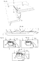
- Figures 5a -5e show vertical folding of three panels wherein the long edges 2,2' are connected with angling and the short edges 1, 1' with a scissor like motion that combines angling and vertical displacement.
- Figure 5b shows that the displaceable tongue is gradually inserted into the tongue groove 20 from one part of the edges that is adjacent to the installed long edge 2 to the other free long edge.
- Figure 5c shows the tongue in the cross section A-A and figures 5d, 5e show the tongue position in the cross sections B-B, and C-C.
- the strip 6 and the locking element 8 are in this embodiment designed such that they bend backwards during locking and this facilitates locking since the necessary flexibility may be provided partly or completely with such strip bending.
- the locking groove is positioned vertically under the lower part of the displacement groove 40.
- Figure 6a shows that the locking system may be formed such that several parts are flexible for example the protrusion 34, the locking strip 6 and the locking element 8. This flexibility may be used to reduce or eliminate production tolerances and to facilitate an easy and strong locking.
- Figure 6a shows that the strip 6 may be bent downwards and the locking element 8 may be bent downwards and outwardly. Such a strip bending may facilitate locking that may even be accomplished with a displaceable tongue that comprises a limited flexibility such as a tongue that essentially comprises wood fibre material.
- a locking may be accomplished with a flexibility where a part of the displaceable tongue 30 is bended or compressed marginally for example only about 0,1 - 1,0 mm in the horizontal direction.
- Figure 6b and 6c show embodiments of the tongue.
- the displaceable tongue 30 may be fixed into the displaceable groove with a friction connection 38.
- the protrusion 34 may comprise flexible parts 39 that create a pre tension against the tongue groove 20.
- the cavity 35 may be considerably larger than the protrusion and preferably there is a space S that may be about 1-3 mm.
- Figure 6d shows a locking system with a sliding surface 45 that protrudes beyond a vertical plane VP.
- the tongue groove 20 is preferably formed on an inclined edge surface 46.
- Such an embodiment offers the advantages that the displaceable tongue 30 may be pressed inwardly and the conventional two-way snapping action may be combined with a one way pressing motion that may be used to create the final locking.
- Figure 6e shows a separate tongue 30, located in a sideway open groove 40 on the second panel 1', comprising an upwardly extending snap tab 47 that cooperates with a downwardly extending sliding surface 45 that is located on the first panel 1 and that protrudes beyond the upper edge and the vertical plane VP.
- the second panel 1' comprises preferably an inclined edge surface 46' located above and and/or below the tongue 30.
- the snap tab may be replaced with a displaceable tongue that comprises flexible snapping protrusions along its length.
- the locking system shown in figure 1d may also be adjusted such that it comprises inclined edge surfaces and such a design may be used to increase the strength of the joint.
- the locking system in a non-claimed aspect may also be formed without a locking grove 14 and a locking element 8 such that it only locks the edges in a vertical direction.
- the locking element 8 may be replaced with local protrusions that extend upwards from a strip 6 and are in locked position located in the cavities.
- the short edges may be locked horizontally by friction between the long edges.
- All locking systems may be designed such that they can be unlocked with angling and/or sliding along the edges.
- Figure 7a, 7b show a tongue blank 43 that comprise several displaceable tongues that are preferably asymmetric along the tongue length.
- Figure 7a shows injection-moulded tongues 30 and figure 7b shows displaceable tongues 30 made of a wood based material that is preferably machined and punched.
- the cavities 35 that are preferably formed by rotating saw blades comprises an upper part that is rounded and may comprise an inner part that is located below an outer part.
- the locking system may be partly or completely formed by carving tools.
Landscapes
- Engineering & Computer Science (AREA)
- Architecture (AREA)
- Civil Engineering (AREA)
- Structural Engineering (AREA)
- Floor Finish (AREA)
- Joining Of Building Structures In Genera (AREA)
- Connection Of Plates (AREA)
Priority Applications (2)
| Application Number | Priority Date | Filing Date | Title |
|---|---|---|---|
| EP20192928.8A EP3760812B1 (en) | 2011-07-19 | 2012-07-11 | Mechanical locking system for building panels |
| PL16184205T PL3135838T3 (pl) | 2011-07-19 | 2012-07-11 | Mechaniczny system blokujący paneli podłogowych |
Applications Claiming Priority (4)
| Application Number | Priority Date | Filing Date | Title |
|---|---|---|---|
| US201161509309P | 2011-07-19 | 2011-07-19 | |
| SE1150713 | 2011-07-19 | ||
| EP12815189.1A EP2734684B1 (en) | 2011-07-19 | 2012-07-11 | Mechanical locking system for floor panels |
| PCT/SE2012/050828 WO2013012386A1 (en) | 2011-07-19 | 2012-07-11 | Mechanical locking system for floor panels |
Related Parent Applications (1)
| Application Number | Title | Priority Date | Filing Date |
|---|---|---|---|
| EP12815189.1A Division EP2734684B1 (en) | 2011-07-19 | 2012-07-11 | Mechanical locking system for floor panels |
Related Child Applications (1)
| Application Number | Title | Priority Date | Filing Date |
|---|---|---|---|
| EP20192928.8A Division EP3760812B1 (en) | 2011-07-19 | 2012-07-11 | Mechanical locking system for building panels |
Publications (2)
| Publication Number | Publication Date |
|---|---|
| EP3135838A1 EP3135838A1 (en) | 2017-03-01 |
| EP3135838B1 true EP3135838B1 (en) | 2020-09-02 |
Family
ID=47558358
Family Applications (3)
| Application Number | Title | Priority Date | Filing Date |
|---|---|---|---|
| EP16184205.9A Active EP3135838B1 (en) | 2011-07-19 | 2012-07-11 | Mechanical locking system for floor panels |
| EP12815189.1A Active EP2734684B1 (en) | 2011-07-19 | 2012-07-11 | Mechanical locking system for floor panels |
| EP20192928.8A Active EP3760812B1 (en) | 2011-07-19 | 2012-07-11 | Mechanical locking system for building panels |
Family Applications After (2)
| Application Number | Title | Priority Date | Filing Date |
|---|---|---|---|
| EP12815189.1A Active EP2734684B1 (en) | 2011-07-19 | 2012-07-11 | Mechanical locking system for floor panels |
| EP20192928.8A Active EP3760812B1 (en) | 2011-07-19 | 2012-07-11 | Mechanical locking system for building panels |
Country Status (18)
| Country | Link |
|---|---|
| EP (3) | EP3135838B1 (pl) |
| JP (1) | JP6005154B2 (pl) |
| KR (1) | KR102083655B1 (pl) |
| CN (2) | CN103703197B (pl) |
| AU (1) | AU2012284623C1 (pl) |
| BR (1) | BR112014000516B1 (pl) |
| CA (1) | CA2841240C (pl) |
| ES (1) | ES2602317T3 (pl) |
| HU (1) | HUE030211T2 (pl) |
| MX (1) | MX344603B (pl) |
| MY (1) | MY164102A (pl) |
| PH (1) | PH12013502648A1 (pl) |
| PL (2) | PL2734684T3 (pl) |
| PT (1) | PT2734684T (pl) |
| RS (1) | RS55314B1 (pl) |
| RU (2) | RU2721838C2 (pl) |
| UA (1) | UA114404C2 (pl) |
| WO (1) | WO2013012386A1 (pl) |
Families Citing this family (19)
| Publication number | Priority date | Publication date | Assignee | Title |
|---|---|---|---|---|
| SE533410C2 (sv) | 2006-07-11 | 2010-09-14 | Vaelinge Innovation Ab | Golvpaneler med mekaniska låssystem med en flexibel och förskjutbar tunga samt tunga därför |
| US9725912B2 (en) | 2011-07-11 | 2017-08-08 | Ceraloc Innovation Ab | Mechanical locking system for floor panels |
| US8650826B2 (en) | 2011-07-19 | 2014-02-18 | Valinge Flooring Technology Ab | Mechanical locking system for floor panels |
| US8857126B2 (en) | 2011-08-15 | 2014-10-14 | Valinge Flooring Technology Ab | Mechanical locking system for floor panels |
| AU2013348454C1 (en) * | 2012-11-22 | 2017-11-09 | Ceraloc Innovation Ab | Mechanical locking system for floor panels |
| HUE060779T2 (hu) | 2013-06-27 | 2023-04-28 | Vaelinge Innovation Ab | Mechanikus rögzítõrendszerrel ellátott építõpanel |
| US10246883B2 (en) | 2014-05-14 | 2019-04-02 | Valinge Innovation Ab | Building panel with a mechanical locking system |
| CN107002411B (zh) | 2014-11-27 | 2020-06-16 | 瓦林格创新股份有限公司 | 用于地板镶板的机械锁定系统 |
| NL2018781B1 (en) * | 2017-04-26 | 2018-11-05 | Innovations4Flooring Holding N V | Panel and covering |
| CN107100343A (zh) * | 2017-06-28 | 2017-08-29 | 黑龙江省木材科学研究所 | 一种带有弹性条的锁扣地板结构 |
| SE542114C2 (en) * | 2018-01-27 | 2020-02-25 | Ipendor Ab | Joining system for floor panels |
| NL2021886B1 (en) * | 2018-10-26 | 2020-05-13 | I4F Licensing Nv | Panel, in particular a floor panel or wall panel, and panel covering |
| EA202191810A1 (ru) | 2019-01-10 | 2021-10-05 | Велинге Инновейшн Аб | Система разблокирования для панелей |
| EP3918150B1 (en) * | 2019-01-30 | 2024-12-18 | I4F Licensing Nv | Panel and floor covering comprising such panels |
| CN114207299B (zh) * | 2019-01-30 | 2023-08-25 | I4F许可有限责任公司 | 地板镶板和地板覆盖物 |
| NL2024191B1 (en) * | 2019-11-08 | 2021-07-20 | I4F Licensing Nv | Panel, in particular a floor panel or a wall panel |
| EP3834661A1 (en) * | 2019-12-11 | 2021-06-16 | Välinge Innovation AB | Mechanical locking system for panels |
| WO2021126070A1 (en) * | 2019-12-19 | 2021-06-24 | Välinge Innovation AB | Set of panels with a mechanical locking device |
| CN117489068A (zh) * | 2023-10-12 | 2024-02-02 | 中国一冶集团有限公司 | 一种循环利用的模块化拼接橡胶地板及施工方法 |
Family Cites Families (18)
| Publication number | Priority date | Publication date | Assignee | Title |
|---|---|---|---|---|
| US7896571B1 (en) * | 1999-06-30 | 2011-03-01 | Akzenta Paneele + Profile Gmbh | Panel and panel fastening system |
| JP2005207010A (ja) * | 2004-01-20 | 2005-08-04 | Eidai Co Ltd | 床板 |
| SI1650375T2 (sl) * | 2004-10-22 | 2011-04-29 | Vaelinge Innovation Ab | Set talnih panelov |
| US8061104B2 (en) * | 2005-05-20 | 2011-11-22 | Valinge Innovation Ab | Mechanical locking system for floor panels |
| SE529076C2 (sv) * | 2005-07-11 | 2007-04-24 | Pergo Europ Ab | En fog till paneler |
| BE1017157A3 (nl) * | 2006-06-02 | 2008-03-04 | Flooring Ind Ltd | Vloerbekleding, vloerelement en werkwijze voor het vervaardigen van vloerelementen. |
| SE531110C2 (sv) * | 2006-07-14 | 2008-12-23 | Vaelinge Innovation Ab | Låssystem omfattande ett kombinationslås för paneler |
| SE532607C2 (sv) * | 2006-11-15 | 2010-03-02 | Vaelinge Innovation Ab | Mekanisk låsning av golvpaneler med vertikal vikning |
| SE531111C2 (sv) * | 2006-12-08 | 2008-12-23 | Vaelinge Innovation Ab | Mekanisk låsning av golvpaneler |
| DE102007042250B4 (de) * | 2007-09-06 | 2010-04-22 | Flooring Technologies Ltd. | Einrichtung zur Verbindung und Verriegelung zweier Bauplatten, insbesondere Fussbodenpaneele |
| WO2009061279A1 (en) * | 2007-11-07 | 2009-05-14 | Välinge Innovation AB | Mechanical locking of floor panels with vertical snap folding and an installation method to connect such panels |
| CN102066674B (zh) * | 2008-05-15 | 2015-06-03 | 瓦林格创新股份有限公司 | 具有通过磁场启动的机械锁定系统的地板镶板及安装镶板的方法 |
| DE102009022483A1 (de) * | 2009-05-25 | 2010-12-02 | Pergo (Europe) Ab | Set von Paneelen, insbesondere von Fußbodenpaneelen |
| ATE510088T1 (de) * | 2009-06-08 | 2011-06-15 | Flooring Technologies Ltd | Satz aus bauplatten mit einer einrichtung zum verriegeln zweier dieser bauplatten |
| DE102009034902B4 (de) * | 2009-07-27 | 2015-10-01 | Guido Schulte | Belag aus mechanisch miteinander verbindbaren Paneelen |
| DE102009041297B4 (de) * | 2009-09-15 | 2018-10-11 | Guido Schulte | Belag aus mechanisch miteinander verbindbaren Elementen und ein Verfahren zur Herstellung von Elementen |
| WO2011127981A1 (en) * | 2010-04-15 | 2011-10-20 | Spanolux N.V.- Div. Balterio | Floor panel assembly |
| CN201835487U (zh) * | 2010-06-13 | 2011-05-18 | 李新发 | 一种二用楔式锁扣装饰板 |
-
2012
- 2012-07-11 CA CA2841240A patent/CA2841240C/en active Active
- 2012-07-11 WO PCT/SE2012/050828 patent/WO2013012386A1/en not_active Ceased
- 2012-07-11 MY MYPI2013004452A patent/MY164102A/en unknown
- 2012-07-11 CN CN201280034259.7A patent/CN103703197B/zh active Active
- 2012-07-11 KR KR1020147003041A patent/KR102083655B1/ko not_active Expired - Fee Related
- 2012-07-11 EP EP16184205.9A patent/EP3135838B1/en active Active
- 2012-07-11 CN CN201610380081.1A patent/CN105971223B/zh active Active
- 2012-07-11 MX MX2014000388A patent/MX344603B/es active IP Right Grant
- 2012-07-11 RU RU2016140240A patent/RU2721838C2/ru active
- 2012-07-11 JP JP2014521595A patent/JP6005154B2/ja active Active
- 2012-07-11 PH PH1/2013/502648A patent/PH12013502648A1/en unknown
- 2012-07-11 BR BR112014000516-8A patent/BR112014000516B1/pt active IP Right Grant
- 2012-07-11 EP EP12815189.1A patent/EP2734684B1/en active Active
- 2012-07-11 AU AU2012284623A patent/AU2012284623C1/en not_active Ceased
- 2012-07-11 UA UAA201401060A patent/UA114404C2/uk unknown
- 2012-07-11 EP EP20192928.8A patent/EP3760812B1/en active Active
- 2012-07-11 RU RU2014103804/03A patent/RU2602850C2/ru active
- 2012-07-11 RS RS20160953A patent/RS55314B1/sr unknown
- 2012-07-11 ES ES12815189.1T patent/ES2602317T3/es active Active
- 2012-07-11 PL PL12815189T patent/PL2734684T3/pl unknown
- 2012-07-11 HU HUE12815189A patent/HUE030211T2/en unknown
- 2012-07-11 PL PL16184205T patent/PL3135838T3/pl unknown
- 2012-07-11 PT PT128151891T patent/PT2734684T/pt unknown
Non-Patent Citations (1)
| Title |
|---|
| None * |
Also Published As
Similar Documents
| Publication | Publication Date | Title |
|---|---|---|
| EP3135838B1 (en) | Mechanical locking system for floor panels | |
| US10240349B2 (en) | Mechanical locking system for floor panels | |
| EP2740859B1 (en) | Mechanical locking of floor panels | |
| EP2405073B1 (en) | Flooring system comprising mechanically connectable floor panels | |
| KR102180904B1 (ko) | 바닥 패널용 기계식 로킹 시스템 |
Legal Events
| Date | Code | Title | Description |
|---|---|---|---|
| PUAI | Public reference made under article 153(3) epc to a published international application that has entered the european phase |
Free format text: ORIGINAL CODE: 0009012 |
|
| STAA | Information on the status of an ep patent application or granted ep patent |
Free format text: STATUS: REQUEST FOR EXAMINATION WAS MADE |
|
| 17P | Request for examination filed |
Effective date: 20160815 |
|
| AC | Divisional application: reference to earlier application |
Ref document number: 2734684 Country of ref document: EP Kind code of ref document: P |
|
| AK | Designated contracting states |
Kind code of ref document: A1 Designated state(s): AL AT BE BG CH CY CZ DE DK EE ES FI FR GB GR HR HU IE IS IT LI LT LU LV MC MK MT NL NO PL PT RO RS SE SI SK SM TR |
|
| STAA | Information on the status of an ep patent application or granted ep patent |
Free format text: STATUS: EXAMINATION IS IN PROGRESS |
|
| 17Q | First examination report despatched |
Effective date: 20190430 |
|
| GRAP | Despatch of communication of intention to grant a patent |
Free format text: ORIGINAL CODE: EPIDOSNIGR1 |
|
| STAA | Information on the status of an ep patent application or granted ep patent |
Free format text: STATUS: GRANT OF PATENT IS INTENDED |
|
| INTG | Intention to grant announced |
Effective date: 20200309 |
|
| RIN1 | Information on inventor provided before grant (corrected) |
Inventor name: PERVAN, DARKO Inventor name: PERVAN, TONY |
|
| GRAS | Grant fee paid |
Free format text: ORIGINAL CODE: EPIDOSNIGR3 |
|
| GRAA | (expected) grant |
Free format text: ORIGINAL CODE: 0009210 |
|
| STAA | Information on the status of an ep patent application or granted ep patent |
Free format text: STATUS: THE PATENT HAS BEEN GRANTED |
|
| AC | Divisional application: reference to earlier application |
Ref document number: 2734684 Country of ref document: EP Kind code of ref document: P |
|
| AK | Designated contracting states |
Kind code of ref document: B1 Designated state(s): AL AT BE BG CH CY CZ DE DK EE ES FI FR GB GR HR HU IE IS IT LI LT LU LV MC MK MT NL NO PL PT RO RS SE SI SK SM TR |
|
| REG | Reference to a national code |
Ref country code: GB Ref legal event code: FG4D |
|
| REG | Reference to a national code |
Ref country code: AT Ref legal event code: REF Ref document number: 1308963 Country of ref document: AT Kind code of ref document: T Effective date: 20200915 Ref country code: CH Ref legal event code: EP |
|
| REG | Reference to a national code |
Ref country code: DE Ref legal event code: R096 Ref document number: 602012072168 Country of ref document: DE |
|
| REG | Reference to a national code |
Ref country code: IE Ref legal event code: FG4D |
|
| REG | Reference to a national code |
Ref country code: SE Ref legal event code: TRGR |
|
| REG | Reference to a national code |
Ref country code: LT Ref legal event code: MG4D |
|
| PG25 | Lapsed in a contracting state [announced via postgrant information from national office to epo] |
Ref country code: FI Free format text: LAPSE BECAUSE OF FAILURE TO SUBMIT A TRANSLATION OF THE DESCRIPTION OR TO PAY THE FEE WITHIN THE PRESCRIBED TIME-LIMIT Effective date: 20200902 Ref country code: LT Free format text: LAPSE BECAUSE OF FAILURE TO SUBMIT A TRANSLATION OF THE DESCRIPTION OR TO PAY THE FEE WITHIN THE PRESCRIBED TIME-LIMIT Effective date: 20200902 Ref country code: GR Free format text: LAPSE BECAUSE OF FAILURE TO SUBMIT A TRANSLATION OF THE DESCRIPTION OR TO PAY THE FEE WITHIN THE PRESCRIBED TIME-LIMIT Effective date: 20201203 Ref country code: NO Free format text: LAPSE BECAUSE OF FAILURE TO SUBMIT A TRANSLATION OF THE DESCRIPTION OR TO PAY THE FEE WITHIN THE PRESCRIBED TIME-LIMIT Effective date: 20201202 Ref country code: BG Free format text: LAPSE BECAUSE OF FAILURE TO SUBMIT A TRANSLATION OF THE DESCRIPTION OR TO PAY THE FEE WITHIN THE PRESCRIBED TIME-LIMIT Effective date: 20201202 Ref country code: HR Free format text: LAPSE BECAUSE OF FAILURE TO SUBMIT A TRANSLATION OF THE DESCRIPTION OR TO PAY THE FEE WITHIN THE PRESCRIBED TIME-LIMIT Effective date: 20200902 |
|
| REG | Reference to a national code |
Ref country code: NL Ref legal event code: MP Effective date: 20200902 |
|
| PG25 | Lapsed in a contracting state [announced via postgrant information from national office to epo] |
Ref country code: RS Free format text: LAPSE BECAUSE OF FAILURE TO SUBMIT A TRANSLATION OF THE DESCRIPTION OR TO PAY THE FEE WITHIN THE PRESCRIBED TIME-LIMIT Effective date: 20200902 Ref country code: LV Free format text: LAPSE BECAUSE OF FAILURE TO SUBMIT A TRANSLATION OF THE DESCRIPTION OR TO PAY THE FEE WITHIN THE PRESCRIBED TIME-LIMIT Effective date: 20200902 |
|
| PG25 | Lapsed in a contracting state [announced via postgrant information from national office to epo] |
Ref country code: EE Free format text: LAPSE BECAUSE OF FAILURE TO SUBMIT A TRANSLATION OF THE DESCRIPTION OR TO PAY THE FEE WITHIN THE PRESCRIBED TIME-LIMIT Effective date: 20200902 Ref country code: NL Free format text: LAPSE BECAUSE OF FAILURE TO SUBMIT A TRANSLATION OF THE DESCRIPTION OR TO PAY THE FEE WITHIN THE PRESCRIBED TIME-LIMIT Effective date: 20200902 Ref country code: PT Free format text: LAPSE BECAUSE OF FAILURE TO SUBMIT A TRANSLATION OF THE DESCRIPTION OR TO PAY THE FEE WITHIN THE PRESCRIBED TIME-LIMIT Effective date: 20210104 Ref country code: RO Free format text: LAPSE BECAUSE OF FAILURE TO SUBMIT A TRANSLATION OF THE DESCRIPTION OR TO PAY THE FEE WITHIN THE PRESCRIBED TIME-LIMIT Effective date: 20200902 Ref country code: SM Free format text: LAPSE BECAUSE OF FAILURE TO SUBMIT A TRANSLATION OF THE DESCRIPTION OR TO PAY THE FEE WITHIN THE PRESCRIBED TIME-LIMIT Effective date: 20200902 Ref country code: CZ Free format text: LAPSE BECAUSE OF FAILURE TO SUBMIT A TRANSLATION OF THE DESCRIPTION OR TO PAY THE FEE WITHIN THE PRESCRIBED TIME-LIMIT Effective date: 20200902 |
|
| PG25 | Lapsed in a contracting state [announced via postgrant information from national office to epo] |
Ref country code: ES Free format text: LAPSE BECAUSE OF FAILURE TO SUBMIT A TRANSLATION OF THE DESCRIPTION OR TO PAY THE FEE WITHIN THE PRESCRIBED TIME-LIMIT Effective date: 20200902 Ref country code: AL Free format text: LAPSE BECAUSE OF FAILURE TO SUBMIT A TRANSLATION OF THE DESCRIPTION OR TO PAY THE FEE WITHIN THE PRESCRIBED TIME-LIMIT Effective date: 20200902 Ref country code: IS Free format text: LAPSE BECAUSE OF FAILURE TO SUBMIT A TRANSLATION OF THE DESCRIPTION OR TO PAY THE FEE WITHIN THE PRESCRIBED TIME-LIMIT Effective date: 20210102 |
|
| REG | Reference to a national code |
Ref country code: DE Ref legal event code: R097 Ref document number: 602012072168 Country of ref document: DE |
|
| PG25 | Lapsed in a contracting state [announced via postgrant information from national office to epo] |
Ref country code: SK Free format text: LAPSE BECAUSE OF FAILURE TO SUBMIT A TRANSLATION OF THE DESCRIPTION OR TO PAY THE FEE WITHIN THE PRESCRIBED TIME-LIMIT Effective date: 20200902 |
|
| PLBE | No opposition filed within time limit |
Free format text: ORIGINAL CODE: 0009261 |
|
| STAA | Information on the status of an ep patent application or granted ep patent |
Free format text: STATUS: NO OPPOSITION FILED WITHIN TIME LIMIT |
|
| 26N | No opposition filed |
Effective date: 20210603 |
|
| PG25 | Lapsed in a contracting state [announced via postgrant information from national office to epo] |
Ref country code: SI Free format text: LAPSE BECAUSE OF FAILURE TO SUBMIT A TRANSLATION OF THE DESCRIPTION OR TO PAY THE FEE WITHIN THE PRESCRIBED TIME-LIMIT Effective date: 20200902 Ref country code: DK Free format text: LAPSE BECAUSE OF FAILURE TO SUBMIT A TRANSLATION OF THE DESCRIPTION OR TO PAY THE FEE WITHIN THE PRESCRIBED TIME-LIMIT Effective date: 20200902 |
|
| PG25 | Lapsed in a contracting state [announced via postgrant information from national office to epo] |
Ref country code: IT Free format text: LAPSE BECAUSE OF FAILURE TO SUBMIT A TRANSLATION OF THE DESCRIPTION OR TO PAY THE FEE WITHIN THE PRESCRIBED TIME-LIMIT Effective date: 20200902 |
|
| REG | Reference to a national code |
Ref country code: CH Ref legal event code: PL |
|
| PG25 | Lapsed in a contracting state [announced via postgrant information from national office to epo] |
Ref country code: MC Free format text: LAPSE BECAUSE OF FAILURE TO SUBMIT A TRANSLATION OF THE DESCRIPTION OR TO PAY THE FEE WITHIN THE PRESCRIBED TIME-LIMIT Effective date: 20200902 |
|
| PG25 | Lapsed in a contracting state [announced via postgrant information from national office to epo] |
Ref country code: LI Free format text: LAPSE BECAUSE OF NON-PAYMENT OF DUE FEES Effective date: 20210731 Ref country code: CH Free format text: LAPSE BECAUSE OF NON-PAYMENT OF DUE FEES Effective date: 20210731 |
|
| PG25 | Lapsed in a contracting state [announced via postgrant information from national office to epo] |
Ref country code: IE Free format text: LAPSE BECAUSE OF NON-PAYMENT OF DUE FEES Effective date: 20210711 |
|
| PG25 | Lapsed in a contracting state [announced via postgrant information from national office to epo] |
Ref country code: HU Free format text: LAPSE BECAUSE OF FAILURE TO SUBMIT A TRANSLATION OF THE DESCRIPTION OR TO PAY THE FEE WITHIN THE PRESCRIBED TIME-LIMIT; INVALID AB INITIO Effective date: 20120711 Ref country code: CY Free format text: LAPSE BECAUSE OF FAILURE TO SUBMIT A TRANSLATION OF THE DESCRIPTION OR TO PAY THE FEE WITHIN THE PRESCRIBED TIME-LIMIT Effective date: 20200902 |
|
| P01 | Opt-out of the competence of the unified patent court (upc) registered |
Effective date: 20230522 |
|
| PG25 | Lapsed in a contracting state [announced via postgrant information from national office to epo] |
Ref country code: MK Free format text: LAPSE BECAUSE OF FAILURE TO SUBMIT A TRANSLATION OF THE DESCRIPTION OR TO PAY THE FEE WITHIN THE PRESCRIBED TIME-LIMIT Effective date: 20200902 |
|
| PGFP | Annual fee paid to national office [announced via postgrant information from national office to epo] |
Ref country code: GB Payment date: 20240620 Year of fee payment: 13 |
|
| PGFP | Annual fee paid to national office [announced via postgrant information from national office to epo] |
Ref country code: LU Payment date: 20240619 Year of fee payment: 13 |
|
| PGFP | Annual fee paid to national office [announced via postgrant information from national office to epo] |
Ref country code: FR Payment date: 20240619 Year of fee payment: 13 |
|
| PGFP | Annual fee paid to national office [announced via postgrant information from national office to epo] |
Ref country code: PL Payment date: 20240619 Year of fee payment: 13 |
|
| PGFP | Annual fee paid to national office [announced via postgrant information from national office to epo] |
Ref country code: SE Payment date: 20240619 Year of fee payment: 13 Ref country code: BE Payment date: 20240619 Year of fee payment: 13 |
|
| PG25 | Lapsed in a contracting state [announced via postgrant information from national office to epo] |
Ref country code: MT Free format text: LAPSE BECAUSE OF FAILURE TO SUBMIT A TRANSLATION OF THE DESCRIPTION OR TO PAY THE FEE WITHIN THE PRESCRIBED TIME-LIMIT Effective date: 20200902 |
|
| PGFP | Annual fee paid to national office [announced via postgrant information from national office to epo] |
Ref country code: AT Payment date: 20240620 Year of fee payment: 13 |
|
| REG | Reference to a national code |
Ref country code: AT Ref legal event code: UEP Ref document number: 1308963 Country of ref document: AT Kind code of ref document: T Effective date: 20200902 |
|
| PGFP | Annual fee paid to national office [announced via postgrant information from national office to epo] |
Ref country code: TR Payment date: 20250624 Year of fee payment: 14 |
|
| PGFP | Annual fee paid to national office [announced via postgrant information from national office to epo] |
Ref country code: DE Payment date: 20250620 Year of fee payment: 14 |
|
| REG | Reference to a national code |
Ref country code: AT Ref legal event code: MM01 Ref document number: 1308963 Country of ref document: AT Kind code of ref document: T Effective date: 20250711 |
|
| PG25 | Lapsed in a contracting state [announced via postgrant information from national office to epo] |
Ref country code: LU Free format text: LAPSE BECAUSE OF NON-PAYMENT OF DUE FEES Effective date: 20250711 |
|
| GBPC | Gb: european patent ceased through non-payment of renewal fee |
Effective date: 20250711 |
|
| REG | Reference to a national code |
Ref country code: BE Ref legal event code: MM Effective date: 20250731 |
|
| PG25 | Lapsed in a contracting state [announced via postgrant information from national office to epo] |
Ref country code: GB Free format text: LAPSE BECAUSE OF NON-PAYMENT OF DUE FEES Effective date: 20250711 |
|
| PG25 | Lapsed in a contracting state [announced via postgrant information from national office to epo] |
Ref country code: AT Free format text: LAPSE BECAUSE OF NON-PAYMENT OF DUE FEES Effective date: 20250711 |
|
| PG25 | Lapsed in a contracting state [announced via postgrant information from national office to epo] |
Ref country code: BE Free format text: LAPSE BECAUSE OF NON-PAYMENT OF DUE FEES Effective date: 20250731 |
|
| PG25 | Lapsed in a contracting state [announced via postgrant information from national office to epo] |
Ref country code: FR Free format text: LAPSE BECAUSE OF NON-PAYMENT OF DUE FEES Effective date: 20250731 |