EP3135567A1 - Fahrzeug, insbesondere nutzfahrzeug mit einer schlafliege mit einem liegemodul - Google Patents
Fahrzeug, insbesondere nutzfahrzeug mit einer schlafliege mit einem liegemodul Download PDFInfo
- Publication number
- EP3135567A1 EP3135567A1 EP16001841.2A EP16001841A EP3135567A1 EP 3135567 A1 EP3135567 A1 EP 3135567A1 EP 16001841 A EP16001841 A EP 16001841A EP 3135567 A1 EP3135567 A1 EP 3135567A1
- Authority
- EP
- European Patent Office
- Prior art keywords
- vehicle
- module
- vehicle according
- lying
- lying module
- Prior art date
- Legal status (The legal status is an assumption and is not a legal conclusion. Google has not performed a legal analysis and makes no representation as to the accuracy of the status listed.)
- Granted
Links
Images



Classifications
-
- B—PERFORMING OPERATIONS; TRANSPORTING
- B62—LAND VEHICLES FOR TRAVELLING OTHERWISE THAN ON RAILS
- B62D—MOTOR VEHICLES; TRAILERS
- B62D33/00—Superstructures for load-carrying vehicles
- B62D33/06—Drivers' cabs
- B62D33/0612—Cabins with living accommodation, especially for long distance road vehicles, i.e. sleeping, cooking, or other facilities
Definitions
- the invention relates to a vehicle, in particular a utility vehicle, with a bunk with a lying module according to the preamble of claim 1.
- a commercial vehicle with a bunk in particular a cab of a truck with a bunk, each directly or indirectly has a firm connection with the vehicle body is well known.
- the disadvantage however, in an inclined position of the cab at rest (parking position) so that the sleeping berth with their reclining module a corresponding tilt.
- An ergonomically optimal sleeping position for a driver or passenger is no longer given.
- a bunk in a cab is well known, which is pivotally mounted about an axis. Even so, an optimal reclining position is only insufficiently feasible.
- the object of the invention is to develop a vehicle, in particular a commercial vehicle, with a bunk so that at all in idle state (parking position) possible inclinations of the vehicle, or a cab, a best possible sleeping position for a driver / passenger is produced.
- a vehicle in particular a commercial vehicle, is provided with a sleeping berth with a lying module, which is connected to a holding device with the vehicle body.
- the holding device forms or has a leveling device by means of which the lying module of the sleeping berth can be leveled and / or brought into a horizontal position with respect to an inclined position of the vehicle body.
- a horizontal sleeping position can be adjusted even with vehicle inclinations.
- the holding device for the recliner module for a leveling of the reclining module with respect to a tilt of the vehicle body in a vehicle rest position, at least one ball joint and / or several, preferably at least three, height-adjustable lifting elements is preferably provided that the several preferably at least three height-adjustable lifting elements spaced and / or offset from one another in the transverse and in the longitudinal direction of the reclining module, that the reclining module about a longitudinal and / or transverse axis displaceable, preferably pivotable, is.
- These several, preferably at least three, lifting elements may not be arranged in a longitudinal direction for compensation with respect to an oblique position of the vehicle about a longitudinal and / or transverse axis.
- the surface of the triangle which is spanned therewith and thus the lying module can be tilted about a longitudinal axis and / or transverse axis such that a leveling to a horizontal position is possible with respect to the vehicle body.
- a leveling can also be achieved in that the lying module is arranged on a pivotable about a longitudinal axis and / or transverse axis and lockable ball joint.
- the lying module has a flat and / or rectangular shape, wherein it is preferably provided that one lifting element is assigned to each of the four sides of the rectangle, preferably each arranged in a central region of each of the four sides of the rectangle.
- substantially four lifting elements are thus used, which are each arranged individually in, for example, a central region of each of the four sides of the rectangle. This makes a particularly simple adjustment and leveling of the reclining module possible.
- the lying module should preferably be constructed of a base frame and / or of a base plate optionally with a peripheral edge and with a slatted base and a mattress lying thereon or lying.
- the lifting elements are preferably independently controllable for height adjustment and leveling.
- lifting elements can in principle many known per se components, such as telescopic supports, scissor elements, etc. are used.
- lifting elements it is particularly advantageous to use lifting elements as actuators of the type of independently controllable bellows or cushions, since they can be used cost-effectively and with low weight for safe operation.
- a controllable multi-chamber air bellows system can be used cost-effectively and functionally reliably, which can be used with compressed air as the working medium from a
- Vehicle electrical system can be operated.
- the use of a separate, optionally fully or partially integrated in the lying module, compressor unit is possible depending on the circumstances.
- controllable multi-chamber hydraulic bellows system which is operated with a liquid working medium, for example oil or water as the working medium, and / or has a pressure compensation element and / or a compressor unit, preferably fully or partially integrated in the lying module.
- a vehicle resting position and a vehicle inclination or inclined position are detected by a sensor system.
- the lifting elements for leveling at a determined vehicle rest position and vehicle inclination by means of a control / electrical control electronics / electronics can be automatically actuated or activated.
- an individual operator preferably a driver or front passenger, should also be able to set the recliner module in a horizontal position or, if appropriate, individually according to their own needs by means of an operating unit via the control / electric system / electronics.
- the operating unit for activating and / or deactivating the regulating / control electrics or electronics can at least one switch and / or at least one push-button and / or at least one remote control element and / or an app for activation / control by means of a control device, preferably a mobile data processing device (tablet PC, mobile phone, etc.) and / or a vehicle key or the like as a control device, have.
- the control can be wired or wireless.
- the lying module can also level by its own weight by the recliner module via a connected by means of communicating lines bellows or pad system, which preferably forms lifting elements of the holding device is supported, wherein it is preferably provided that as a working fluid, in particular water or Oil, is used. Similar to a per se known hose scale then distributes the working fluid in bellows or cushion system, so that by an overflow from the higher bellows in a lower bellows, the initially higher extended bellows reduced in height and the lower is raised so far that the lying module is horizontal.
- a working fluid in particular water or Oil
- the lying module on a base plate and / or a base frame, wherein a ball joint is arranged centrally under the base plate and connected thereto, wherein an angular displacement of the ball joint is feasible.
- a ball joint is arranged centrally under the base plate and connected thereto, wherein an angular displacement of the ball joint is feasible.
- a set angular position is fixed, preferably fixed by means of a fixing device, such as a magnetic fuse.
- the recliner module is expediently held on the structure with at least one support and / or guide and works during an adjustment against a mechanical force.
- the reclining module should be able to be secured in particular rattle-free in a basic position on fixed supports as well as in a level adjustment by means of the kinematics and / or locking components.
- the lying module can be designed to be foldable by means of kinematics, for example in the form of hinges. This, for example, in particular to gain access to one or more storage spaces.
- the inventive device is particularly suitable for a truck with a cab, in which a bunk, preferably transversely in the area behind the seats, is arranged.
- a commercial vehicle 1 shown as a tractor of a tractor-trailer with a cab 2 in a rest position (parking position), in which it is parked on an inclined surface 3.
- the inclined surface 3 is inclined laterally with respect to the cab 2 and forward.
- a arranged in the cab 2 bunk would also be inclined at a fixed installation according to the actual lines 4, 5.
- a lying module 8 according to the lines 6, 7 by a leveling about horizontal to be adjustable, as explained in the following:
- Fig. 3 is shown in perspective a lying module 8 a bunk, which is arranged in the cab 2.
- the lying module 8 is pivotable for a leveling or individual adjustment in an optimal reclining position about its longitudinal axis or direction 9 and transverse axis or - direction 10 in both directions, whereby the longitudinal and transverse positions of the cab 2 can be compensated.
- each end a pivot lever 11 as a kinematics for unfolding the deck module 8, in particular for access to a storage space arranged.
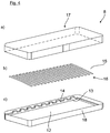
- Fig. 4c shows a rectangular base plate 12 with a circumferential base frame 13 having recesses 14 on the longitudinal side for receiving slats 15, whereby a slatted frame 16 is formed.
- a mattress 17 On the slatted base is a mattress 17, which is held non-slip in its position by the upwardly projecting edge 18 on the base plate 12.
- Fig. 5 is a view from below and in Fig. 6 a view from the side of the recliner module 8 shown.
- the here exemplary central region of each of the four sides of the rectangular base plate 12 are slightly offset inwardly lifting elements as air bellows 19, 20, 21, 22 mounted in a controllable multi-chamber Heilbalgsystem.
- the lying on the narrow sides Bellows 19, 20 are cylindrical with a relatively small diameter, while arranged on the longitudinal sides of the air bellows 21, 22 have a longitudinal extent.
- the air bellows 19 to 22 preferably operated with compressed air from the electrical system and are controlled independently of each other so that they as lifting elements with respect to their (not shown) edition and thus with respect to the cab, the lying module 8 to the longitudinal and / or one Can pivot transverse axis.
- a vehicle rest position in conjunction with a vehicle inclination can be detected, in particular, by a vehicle-side sensor system or by means of information already present on the vehicle side.
- a leveling of the reclining module 8 can then be carried out automatically, for example by means of a control / electrical system / electronics or an adjustment can be made according to individual needs by a driver / passenger with a suitable control unit.
- FIG. 7 An alternative adjustment without air bellows, for example, by a centrally disposed below the base plate 12 ball joint 24 as possible in Fig. 7 is shown schematically. Also pivoting adjustments of the reclining module 8 are possible, as indicated by the arrow cross 25. Especially in such an embodiment, supports / guides 26 with respect to the base of the reclining module 8 are appropriate, as in the corner areas in Fig. 5 are shown.
- the lifting elements can each be connected at the end to the lying module 8 and the base. In particular, in conjunction with guide elements, the lifting elements may optionally also be attached only to the pad or the lying module 8 and lie opposite freely for an adjustment.
Landscapes
- Engineering & Computer Science (AREA)
- Chemical & Material Sciences (AREA)
- Combustion & Propulsion (AREA)
- Transportation (AREA)
- Mechanical Engineering (AREA)
- Seats For Vehicles (AREA)
Abstract
Description
- Die Erfindung betrifft ein Fahrzeug, insbesondere ein Nutzfahrzeug, mit einer Schlafliege mit einem Liegemodul nach dem Oberbegriff des Anspruchs 1.
- Ein Nutzfahrzeug mit einer Schlafliege, insbesondere ein Fahrerhaus eines Lastkraftwagens mit einer Schlafliege, die jeweils direkt oder indirekt eine feste Verbindung mit dem Fahrzeugaufbau hat ist allgemein bekannt. Nachteilig hat jedoch bei einer Schräglage des Fahrerhauses im Ruhezustand (Parkposition) damit auch die Schlafliege mit ihrem Liegemodul eine entsprechende Schräglage. Eine ergonomisch optimale Schlafposition für einen Fahrer oder Beifahrer ist dadurch nicht mehr gegeben. Zudem ist eine Schlafliege in einem Fahrerhaus allgemein bekannt, die um eine Achse schwenkbar gelagert ist. Auch damit ist eine optimale Liegeposition nur unzureichend realisierbar.
- Aufgabe der Erfindung ist es, ein Fahrzeug, insbesondere ein Nutzfahrzeug, mit einer Schlafliege so weiterzubilden, dass bei allen im Ruhezustand (Parkposition) möglichen Schräglagen des Fahrzeugs, bzw. eines Fahrerhauses, eine bestmögliche Schlafposition für einen Fahrer/Beifahrer herstellbar ist.
- Diese Aufgabe wird gelöst mit den Merkmalen der unabhängigen Patentansprüche. Vorteilhafte Ausgestaltungen sind Gegenstand der darauf rückbezogenen Unteransprüche.
- Gemäß Anspruch 1 ist ein Fahrzeug, insbesondere ein Nutzfahrzeug, mit einer Schlafliege mit einem Liegemodul vorgesehen, das mit einer Haltevorrichtung mit dem Fahrzeugaufbau verbunden ist. Erfindungsgemäß ist vorgesehen, dass die Haltevorrichtung eine Nivelliervorrichtung ausbildet oder aufweist, mittels der das Liegemodul der Schlafliege nivellierbar ist und/oder in eine waagrechte Position bezüglich einer Schräglage des Fahrzeugaufbaus gebracht werden kann. Damit kann auch bei Fahrzeug-Schräglagen eine waagrechte Schlafposition eingestellt werden.
- Bevorzugt ist die Haltevorrichtung für das Liegemodul, für eine Nivellierung des Liegemoduls bezüglich einer Schräglage des Fahrzeugaufbaus in einer Fahrzeug-Ruheposition, aus wenigstens einem Kugelgelenk und/oder aus mehreren, vorzugsweise wenigstens drei, höhenverstellbaren Hubelementen ausgebildet ist, wobei bevorzugt vorgesehen ist, dass die mehreren, vorzugsweise wenigstens drei, höhenverstellbaren Hubelemente derart voneinander in Quer- und in Längsrichtung des Liegemoduls beabstandet und/oder versetzt sind, dass das Liegemodul um eine Längs- und/oder Querachse verlagerbar, vorzugsweise verschwenkbar, ist. Diese mehreren, vorzugsweise wenigstens drei, Hubelemente dürfen für einen Ausgleich bezüglich einer Schräglage des Fahrzeugs um eine Längs- und/oder Querachse ersichtlich nicht in einer Längsrichtung angeordnet sein. Bei einer Anordnung in zum Beispiel einer Dreieckform zwischen Liegemodul und Fahrzeugaufbau kann die Fläche des damit aufgespannten Dreiecks und damit das Liegemodul so um eine Längsachse und/oder Querachse gekippt werden, dass bezüglich des Fahrzeugaufbaus eine Nivellierung zu einer waagrechten Position möglich ist. Alternativ kann eine solche Nivellierung aber auch dadurch erreicht werden, dass das Liegemodul auf einem um eine Längsachse und/oder Querachse schwenkbaren und arretierbaren Kugelgelenk angeordnet ist. Durch die angegebene Stelleinrichtungen ist es möglich, eine optimale Schlafposition für einen Fahrer/Beifahrer einzustellen.
- In einer bevorzugten Ausführungsform weist das Liegemodul eine flache und/oder rechteckige Form auf, wobei bevorzugt vorgesehen ist, dass je ein Hubelement einer der vier Rechteckseiten zugeordnet ist, vorzugsweise jeweils in einem mittleren Bereich jeder der vier Rechteckseiten angeordnet ist. Bei einem derartigen Aufbau werden somit im Wesentlichen vier Hubelemente verwendet, die jeweils einzeln in zum Beispiel einem mittleren Bereich jeder der vier Rechteckseiten angeordnet sind. Damit ist eine besonders einfache Einstellung und Nivellierung des Liegemoduls möglich. Das Liegemodul soll dabei vorzugsweise aus einem Basisrahmen und/oder aus einer Basisplatte gegebenenfalls mit umlaufendem Rand und mit einem darauf liegenden oder einliegenden Lattenrost und einer Matratze aufgebaut sein.
- Die Hubelemente sind für eine Höheneinstellung und Nivellierung bevorzugt unabhängig voneinander steuerbar. Als Hubelemente können grundsätzlich viele an sich bekannten Bauelemente, wie Teleskopstützen, Scherenelemente, etc. verwendet werden. Besonders vorteilhaft werden aber Hubelemente als Aktuatoren in der Art unabhängig steuerbarer Bälge oder Kissen eingesetzt, da diese bei sicherer Funktion kostengünstig und gewichtsgünstig eingesetzt werden können.
- Besonders bevorzugt kann kostengünstig und funktionssicher ein steuerbares Mehrkammer-Luftbalgsystem verwendet werden, welches mit Druckluft als Arbeitsmedium aus einem
- Fahrzeug-Bordnetz betrieben werden kann. Auch der Einsatz einer separaten, gegebenenfalls im Liegemodul voll- oder teilintegrierten, Kompressoreinheit ist je nach den Gegebenheiten möglich.
- Alternativ kann auch ein steuerbares Mehrkammer-Hydraulikbalgsystem verwendet werden, das mit einem flüssigen Arbeitsmedium, beispielsweise Öl oder Wasser als Arbeitsmedium, betrieben wird und/oder ein Druckausgleichselement und/oder eine, vorzugsweise voll- oder teilweise in das Liegemodul integrierte, Kompressoreinheit aufweist.
- Je nach den Gegebenheiten können selbstverständlich auch Systeme mit Kombinationen von Arbeitsmedien, wie Luft/Öl, Luft/Wasser, etc. betrieben werden.
- Bei einer besonders komfortablen Nivellierungseinrichtung werden gegebenenfalls eine Fahrzeugruheposition und eine Fahrzeugneigung bzw. Schräglage durch eine Sensorik festgestellt. Insbesondere für diesen Fall (aber nicht ausschließlich für diesen Fall) können die Hubelemente zur Nivellierung bei festgestellter Fahrzeug-Ruheposition und Fahrzeug-Neigung mittels einer Regel-/Steuer-Elektrik/Elektronik selbsttätig betätigbar bzw. aktivierbar sein. Alternativ oder zusätzlich soll auch individuell eine Bedienperson, vorzugsweise ein Fahrer oder Beifahrer, das Liegemodul in eine waagrechte Position oder gegebenenfalls individuell nach eigenen Bedürfnissen mittels einer Bedieneinheit über die Regel-/Steuer-Elektrik/Elektronik einstellen können.
- Grundsätzlich können dazu unterschiedliche, allgemein bekannte Bedieneinheiten verwendet werden. Insbesondere kann die Bedieneinheit zur Aktivierung und/oder Deaktivierung der Regel-/Steuer-Elektrik oder -Elektronik wenigstens einen Schalter und/oder wenigstens einen Taster und/oder wenigstens ein Fernbedienungselement und/oder eine App für eine Aktivierung/Steuerung mittels einer Steuereinrichtung, vorzugsweise einer mobilen Datenverarbeitungseinrichtung (Tablet-PC, Mobiltelefon, etc.) und/oder einem Fahrzeugschlüssel oder ähnliches als Steuereinrichtung, aufweisen. Die Ansteuerung kann dabei kabelgebunden oder kabellos erfolgen.
- Alternativ kann sich das Liegemodul auch durch sein Eigengewicht selbst nivellieren, indem das Liegemodul über ein mittels kommunizierender Leitungen verbundenes Balg- oder Kissensystem, das vorzugsweise Hubelemente der Haltevorrichtung ausbildet, abgestützt ist, wobei bevorzugt vorgesehen ist, dass als Arbeitsmedium eine Flüssigkeit, insbesondere Wasser oder Öl, verwendet wird. Ähnlich wie in einer an sich bekannten Schlauchwaage verteilt sich dann das Arbeitsmedium im Balg- oder Kissensystem, so dass durch ein Überlaufen vom höheren Balg in einen tieferliegenden Balg, der anfänglich höher ausgefahrene Balg in seiner Höhe soweit reduziert und der tiefere soweit angehoben wird, dass das Liegemodul waagrecht liegt.
- In einer weiteren alternativen Anordnung weist das Liegemodul eine Basisplatte und/oder einen Basisrahmen auf, wobei ein Kugelgelenk zentral unter der Basisplatte angeordnet und mit dieser verbunden ist, wobei eine Winkelverstellung des Kugelgelenks durchführbar ist. Durch eine Winkelverstellung des Kugelgelenks, beispielsweise mittels eines Seilzugs und/oder eines Aktuators, kann auch damit das Liegemodul längs und quer für eine Nivellierung in die waagrechte Position verstellt werden. Zweckmäßig wird eine eingestellte Winkellage fixiert, vorzugsweise mittels einer Fixiereinrichtung, wie beispielsweise einer Magnetsicherung, fixiert.
- Konkret wird das Liegemodul zweckmäßig mit wenigstens einer Abstützung und/oder Führung am Aufbau gehalten und arbeitet während einer Verstellung gegen eine mechanische Kraft. Das Liegemodul soll sowohl in einer Grundstellung auf festen Auflagen als auch in einer nivellierten Einstellung mittels der Kinematik und/oder Verriegelungsbauteilen insbesondere klapperfrei gesichert werden können.
- In einer weiteren Ausgestaltung kann das Liegemodul mittels einer Kinematik, zum Beispiel in Form von Scharnieren, klappbar ausgebildet werden. Dies zum Beispiel insbesondere um einen Zugang zu einem oder mehreren Stauräumen zu erhalten.
- Die erfindungsgemäße Einrichtung ist besonders für einen Lastkraftwagen mit einem Fahrerhaus geeignet, in dem eine Schlafliege, vorzugsweise quer im Bereich hinter den Sitzen, angeordnet ist.
- Anhand einer Zeichnung wird die Erfindung weiter erläutert.
- Es zeigen:
- Fig. 1
- eine Zugmaschine mit einem Fahrerhaus in seitlicher Schräglage,
- Fig. 2
- eine Zugmaschine mit Fahrerhaus in Längsschräglage,
- Fig. 3
- eine perspektivische Darstellung eines Liegemoduls einer Schlafliege,
- Fig. 4
- einzelne Bestandteile des Liegemoduls nach
Fig. 3 in einer Explosionsdarstellung, - Fig. 5
- eine Ansicht von unten auf das Liegemodul nach
Fig.3 , - Fig. 6
- eine Seitenansicht des Liegemoduls nach
Fig. 5 , und - Fig. 7
- schematisch ein verstellbares Kugelgelenk mit Magnetsicherung.
- In den
Fig. 1 und 2 ist ein Nutzfahrzeug 1 als Zugmaschine eines Sattelzugs mit einem Fahrerhaus 2 in einer Ruheposition (Parkposition) dargestellt, bei der es auf einer Schrägfläche 3 abgestellt ist. Wie aus denFig. 1 und 2 ersichtlich, ist die Schrägfläche 3 bezüglich des Fahrerhauses 2 seitlich und nach vorne geneigt. Eine im Fahrerhaus 2 angeordnete Schlafliege wäre bei einem festen Einbau entsprechend den Ist-Linien 4, 5 ebenfalls schräg geneigt. Für eine optimale Liegeposition soll ein Liegemodul 8 entsprechend der Linien 6, 7 durch eine Nivellierung etwa waagrecht einstellbar sein, wie dies im Folgendem erläutert ist: - In
Fig. 3 ist perspektivisch ein Liegemodul 8 einer Schlafliege dargestellt, die im Fahrerhaus 2 angeordnet ist. Das Liegemodul 8 ist für eine Nivellierung oder individuelle Einstellung in eine optimale Liegeposition um ihre Längsachse bzw. -richtung 9 und Querachse bzw. - richtung 10 in beide Richtungen verschwenkbar, womit die Längs- und Querstellungen des Fahrerhauses 2 ausgeglichen werden können. - An einer Längsseite des Liegemoduls 8 ist lediglich beispielhaft und schematisch jeweils endseitig ein Schwenkhebel 11 als Kinematik zum Aufklappen des Liegemoduls 8, insbesondere für einen Zugang zu einem Stauraum, angeordnet.
- In
Fig. 4 ist der Aufbau des Liegemoduls 8 in einer Explosionsdarstellung im einzelnen gezeigt:Fig. 4c zeigt eine rechteckige Basisplatte 12 mit einem umlaufenden Basisrahmen 13, der an der Längsseite Ausnehmungen 14 zur Aufnahme von Latten 15 aufweist, wodurch ein Lattenrost 16 gebildet wird. Auf dem Lattenrost liege eine Matratze 17, die durch den nach oben abstehenden Rand 18 an der Basisplatte 12 in ihrer Position rutschsicher gehalten wird. - In
Fig. 5 ist eine Ansicht von unten und inFig. 6 eine Ansicht von der Seite auf das Liegemodul 8 gezeigt. Im hier beispielhaft mittleren Bereich jeder der vier Rechteckseiten der Basisplatte 12 sind etwas nach innen versetzt Hubelemente als Luftbälge 19, 20, 21, 22 in einem steuerbaren Mehrkammer-Luftbalgsystem angebracht. Die an den Schmalseiten liegenden Luftbälge 19, 20 sind mit relativ kleinem Durchmesser zylindrisch ausgebildet, während die an den Längsseiten angeordneten Luftbälge 21, 22 eine Längserstreckung aufweisen. - Wie dies mit den Doppelpfeilen 23 in
Fig. 6 angedeutet ist, können die Luftbälge 19 bis 22 vorzugsweise mit Druckluft aus dem Bordnetz betrieben und so unabhängig voneinander angesteuert werden, dass sie als Hubelemente bezüglich ihrer (nicht dargestellten) Auflage und damit bezüglich des Fahrerhauses das Liegemodul 8 um die Längs- und/oder eine Querachse schwenken können. Eine Fahrzeugruheposition in Verbindung mit einer Fahrzeugneigung kann insbesondere durch eine fahrzeugseitige Sensorik oder mittels ohnehin fahrzeugseitig vorhandenen Informationen erkannt werden. Eine Nivellierung des Liegemoduls 8 kann dann beispielsweise mittels einer Regel-/Steuer-Elektrik/Elektronik selbsttätig erfolgen oder eine Verstellung kann entsprechend individueller Bedürfnisse durch einen Fahrer/Beifahrer mit einer geeigneten Bedieneinheit erfolgen. - Eine alternative Verstellmöglichkeit ohne Luftbälge ist beispielsweise durch ein zentral unter der Basisplatte 12 angeordnetes Kugelgelenk 24 möglich wie dies in
Fig. 7 schematisch dargestellt ist. Auch damit sind Schwenkeinstellungen des Liegemoduls 8 möglich, wie dies durch das Pfeilkreuz 25 angedeutet ist. Gerade bei einer solchen Ausführungsform sind Abstützungen/Führungen 26 bezüglich des Unterbaus des Liegemoduls 8 zweckmäßig, wie sie in den Eckbereichen inFig. 5 dargestellt sind. Die Hubelemente können jeweils endseitig mit dem Liegemodul 8 und der Unterlage verbunden sein. Insbesondere in Verbindung mit Führungselementen können die Hubelemente gegebenenfalls auch nur an der Unterlage oder dem Liegemodul 8 befestigt sein und gegenüberliegend für eine Verstellung frei anliegen. -
- 1
- Nutzfahrzeug
- 2
- Fahrerhaus
- 3
- Schrägfläche
- 4
- Ist-Linie
- 5
- Ist-Linie
- 6
- Linie
- 7
- Linie
- 8
- Liegemodul
- 9
- Längsrichtung
- 10
- Querrichtung
- 11
- Schwenkhebel
- 12
- Basisplatte
- 13
- Basisrahmen
- 14
- Ausnehmung
- 15
- Latte
- 16
- Lattenrost
- 17
- Matratze
- 18
- Rand
- 19
- Luftbalg
- 20
- Luftbalg
- 21
- Luftbalg
- 22
- Luftbalg
- 23
- Doppelpfeil
- 24
- Kugelgelenk
- 25
- Pfeilkreuz
- 26
- Abstützung/Führung
Claims (13)
- Fahrzeug, insbesondere Nutzfahrzeug (1), mit einer Schlafliege mit einem Liegemodul (8), das mit einer Haltevorrichtung mit dem Fahrzeugaufbau verbunden ist, dadurch gekennzeichnet, dass die Haltevorrichtung eine Nivelliervorrichtung ausbildet oder aufweist, mittels der das Liegemodul (8) der Schlafliege nivellierbar ist und/oder in eine waagrechte Position bezüglich einer Schräglage des Fahrzeugaufbaus bringbar ist.
- Fahrzeug nach Anspruch 1, dadurch gekennzeichnet, dass für eine Nivellierung des Liegemoduls (8) bezüglich einer Schräglage des Fahrzeugaufbaus in einer Fahrzeug-Ruheposition die Haltevorrichtung aus wenigstens einem Kugelgelenk (24) und/oder aus mehreren, vorzugsweise wenigstens drei, höhenverstellbaren Hubelementen (19 bis 22) ausgebildet ist, wobei bevorzugt vorgesehen ist, dass die mehreren, vorzugsweise wenigstens drei, höhenverstellbaren Hubelemente (19 bis 22) derart voneinander in Quer- und in Längsrichtung des Liegemoduls (8) beabstandet und/oder versetzt sind, dass das Liegemodul (8) um eine Längs- und/oder Querachse (9, 10) verlagerbar, vorzugsweise verschwenkbar, ist.
- Fahrzeug nach Anspruch 1 oder 2, dadurch gekennzeichnet, dass das Liegemodul (8) eine flache und/oder rechteckige Form aufweist, vorzugsweise aus einem Basisrahmen und/oder eine Basisplatte (12) mit einem Lattenrost (16) und einer Matratze (17) aufgebaut ist, wobei bevorzugt vorgesehen ist, dass je ein Hubelement einer der vier Rechteckseiten zugeordnet ist, vorzugsweise jeweils in einem mittleren Bereich jeder der vier Rechteckseiten angeordnet ist.
- Fahrzeug nach Anspruch 2 oder 3, dadurch gekennzeichnet, dass die Hubelemente für eine Höheneinstellung und Nivellierung unabhängig steuerbar sind, vorzugsweise als Aktuatoren jeweils für eine Höheneinstellung und Nivellierung unabhängig steuerbare Bälge (19 bis 22) und/oder Kissen sind.
- Fahrzeug nach Anspruch 4, dadurch gekennzeichnet, dass ein steuerbares Mehrkammer-Luftbalgsystem (19 bis 22) verwendet ist, welches mit Druckluft als Arbeitsmedium aus einem Fahrzeug-Bordnetz oder mit einer separaten, gegebenenfalls im Liegemodul (8) voll- oder teilintegrierten, Kompressoreinheit betrieben ist.
- Fahrzeug nach Anspruch 4, dadurch gekennzeichnet, dass ein steuerbares Mehrkammer-Hydraulikbalgsystem verwendet ist, welches mit einem flüssigen Arbeitsmedium, vorzugsweise mit Öl oder Wasser als Arbeitsmedium, betrieben wird und/oder ein Druckausgleichselement und/oder eine, vorzugsweise vollständig oder teilweise in das Liegemodul (8) integrierte, Kompressoreinheit aufweist.
- Fahrzeug nach Anspruch 4, dadurch gekennzeichnet, dass die Hubelemente (19 bis 22) zur Nivellierung bei festgestellter Fahrzeug-Ruheposition und Fahrzeug-Neigung mittels einer Regel- /Steuer-Elektrik/Elektronik selbsttätig betätigbar sind und/oder die Hubelemente von einer Bedienperson, vorzugsweise einem Fahrer oder Beifahrer, mit einer Bedieneinheit individuell steuerbar sind.
- Fahrzeug nach Anspruch 7, dadurch gekennzeichnet, dass die Bedieneinheit zur Aktivierung und/oder Deaktivierung der Regel-/Steuer-Elektrik/Elektronik wenigstens einen Schalter und/oder wenigstens einen Taster und/oder wenigstens ein Fernbedienungselement und/oder eine App für eine Aktivierung/Steuerung mittels einer Steuereinrichtung, vorzugsweise einer mobilen Datenverarbeitungseinrichtung und/oder einem Fahrzeugschlüssel als Steuereinrichtung, aufweist.
- Fahrzeug nach einem der Ansprüche 1 bis 3, dadurch gekennzeichnet, dass das Liegemodul (8), vorzugsweise ein eine flache und/oder rechteckige Form aufweisendes Liegemodul (8), durch sein Eigengewicht nivellierbar ist, wobei das Liegemodul (8) über ein mittels kommunizierender Leitungen verbundenes Balg- oder Kissensystem, das vorzugsweise Hubelemente der Haltevorrichtung ausbildet, abgestützt ist, wobei bevorzugt vorgesehen ist, dass als Arbeitsmedium eine Flüssigkeit, insbesondere Wasser oder Öl, verwendet ist.
- Fahrzeug nach Anspruch 1 oder 2, dadurch gekennzeichnet, dass das Liegemodul (8) eine Basisplatte (12) und/oder einen Basisrahmen (13) aufweist und das Kugelgelenk (24) zentral unter der Basisplatte (12) und/oder dem Basisrahmen (13) angeordnet und verbunden ist, wobei eine Winkelverstellung des Kugelgelenks (24), insbesondere mittels eines Seilzugs und/oder eines Aktuators, durchführbar und eine eingestellte Winkellage fixierbar ist, vorzugsweise mittels einer Fixiereinrichtung, höchst bevorzugt mittels einer Magnetsicherung, fixierbar ist.
- Fahrzeug nach einem der vorhergehenden Ansprüche, dadurch gekennzeichnet, dass das Liegemodul (8) mit wenigstens einer Abstützung und/oder Führung gehalten ist und während einer Verstellung gegen eine mechanische Kraft arbeitet und sowohl in einer Grundstellung auf festen Auflagen als auch in einer nivellierten Einstellung mittels der Kinematik und/oder Verriegelungsbauteilen, insbesondere klapperfrei, lagegesichert ist.
- Fahrzeug nach einem der vorhergehenden Ansprüche, dadurch gekennzeichnet, dass das Liegemodul (8) mittels einer Kinematik (11) klappbar ausgebildet ist, insbesondere für einen Zugang zu einem Stauraum.
- Fahrzeug nach einem der vorhergehenden Ansprüche, dadurch gekennzeichnet, dass das Fahrzeug ein Lastkraftwagen mit einem Fahrerhaus (2) ist und die Schlafliege im Fahrerhaus (2), vorzugsweise quer im Bereich hinter den Sitzen, angeordnet ist.
Applications Claiming Priority (1)
| Application Number | Priority Date | Filing Date | Title |
|---|---|---|---|
| DE102015011191.4A DE102015011191A1 (de) | 2015-08-26 | 2015-08-26 | Fahrzeug, insbesondere Nutzfahrzeug mit einer Schlafliege mit einem Liegemodul |
Publications (2)
| Publication Number | Publication Date |
|---|---|
| EP3135567A1 true EP3135567A1 (de) | 2017-03-01 |
| EP3135567B1 EP3135567B1 (de) | 2019-11-06 |
Family
ID=56801335
Family Applications (1)
| Application Number | Title | Priority Date | Filing Date |
|---|---|---|---|
| EP16001841.2A Active EP3135567B1 (de) | 2015-08-26 | 2016-08-23 | Fahrzeug, insbesondere nutzfahrzeug mit einer schlafliege mit einem liegemodul |
Country Status (2)
| Country | Link |
|---|---|
| EP (1) | EP3135567B1 (de) |
| DE (1) | DE102015011191A1 (de) |
Citations (4)
| Publication number | Priority date | Publication date | Assignee | Title |
|---|---|---|---|---|
| DE8913590U1 (de) * | 1989-11-17 | 1990-06-21 | Freizeit - Concept Gesellschaft für Freizeitpublikationen mbH, 5330 Königswinter | Flexible, höhenverstellbare Bettkonstruktion für Wohnwagen und Motorcaravans |
| US20010044959A1 (en) * | 2000-03-08 | 2001-11-29 | Davis Waldon E. | Bed leveler/adjuster |
| US6718574B1 (en) * | 2003-04-02 | 2004-04-13 | International Truck Intellectual Property Company, Llc | Bunk leveling support assembly |
| US20130097782A1 (en) * | 2011-10-21 | 2013-04-25 | Ralph Carrier | Cab sleeper |
-
2015
- 2015-08-26 DE DE102015011191.4A patent/DE102015011191A1/de not_active Withdrawn
-
2016
- 2016-08-23 EP EP16001841.2A patent/EP3135567B1/de active Active
Patent Citations (4)
| Publication number | Priority date | Publication date | Assignee | Title |
|---|---|---|---|---|
| DE8913590U1 (de) * | 1989-11-17 | 1990-06-21 | Freizeit - Concept Gesellschaft für Freizeitpublikationen mbH, 5330 Königswinter | Flexible, höhenverstellbare Bettkonstruktion für Wohnwagen und Motorcaravans |
| US20010044959A1 (en) * | 2000-03-08 | 2001-11-29 | Davis Waldon E. | Bed leveler/adjuster |
| US6718574B1 (en) * | 2003-04-02 | 2004-04-13 | International Truck Intellectual Property Company, Llc | Bunk leveling support assembly |
| US20130097782A1 (en) * | 2011-10-21 | 2013-04-25 | Ralph Carrier | Cab sleeper |
Also Published As
| Publication number | Publication date |
|---|---|
| EP3135567B1 (de) | 2019-11-06 |
| DE102015011191A1 (de) | 2017-03-02 |
Similar Documents
| Publication | Publication Date | Title |
|---|---|---|
| DE102007038829B4 (de) | Vorrichtung zur Körperunterstützung und Verwendung der Vorrichtung in unterschiedlichen Tätigkeitsbereichen eines Benutzers | |
| DE19544014A1 (de) | Klappsitzbank | |
| EP2781402B1 (de) | Fußablage für einen Fahrzeuginsassen | |
| EP1867522A2 (de) | Einbauschlafmöbel zum Einbau in Kastenwagen, Wohnmobilen und dergleichen | |
| WO2018215569A1 (de) | Fahrzeugsitz | |
| DE202008000221U1 (de) | Sitzeinrichtung | |
| EP2832618A1 (de) | Ergonomisch flexibler Fahrerstand eines Schienenfahrzeugs | |
| EP3838635B1 (de) | Nivelliereinrichtung und verfahren zum nivellieren | |
| DE102020117429B4 (de) | Fahrzeugsitz und Fahrzeug mit Fahrzeugsitz | |
| WO2012055691A1 (de) | Sitzuntergestell für kraftfahrzeugsitze | |
| EP2781405B1 (de) | Lagerung für eine Liege in einem Fahrzeug und Verfahren zur Einstellung der Liege | |
| DE8913590U1 (de) | Flexible, höhenverstellbare Bettkonstruktion für Wohnwagen und Motorcaravans | |
| DE10134854A1 (de) | Führerstand für Schienenfahrzeuge | |
| DE112007002640T5 (de) | Fahrzeugsitz | |
| EP3135567B1 (de) | Fahrzeug, insbesondere nutzfahrzeug mit einer schlafliege mit einem liegemodul | |
| EP1232079B1 (de) | Stützvorrichtung | |
| EP3006273B1 (de) | Rückhaltevorrichtung für eine fahrzeug-liege | |
| EP3502039A1 (de) | Flurförderzeug mit einem eine fahrerstandplattform umfassenden fahrerarbeitsplatz | |
| DE102023105590A1 (de) | Fahrzeug mit Lenkrad, das in eine Nichtlenkposition überführbar ist | |
| EP1288113B1 (de) | Fahrerhaus eines Nutzfahrzeugs | |
| DE102009012811A1 (de) | Liege für ein Kraftfahrzeug | |
| DE102005020914B3 (de) | Elektrorollstuhl | |
| EP0613803A1 (de) | Ablage für das Fahrerhaus eines Nutzkraftwagens | |
| DE102006042450A1 (de) | Bedieneinheit für wenigstens einen Einsteller eines Fahrzeugsitzes | |
| WO2021110469A1 (de) | Konsolenelement für ein fahrzeug |
Legal Events
| Date | Code | Title | Description |
|---|---|---|---|
| PUAI | Public reference made under article 153(3) epc to a published international application that has entered the european phase |
Free format text: ORIGINAL CODE: 0009012 |
|
| STAA | Information on the status of an ep patent application or granted ep patent |
Free format text: STATUS: THE APPLICATION HAS BEEN PUBLISHED |
|
| AK | Designated contracting states |
Kind code of ref document: A1 Designated state(s): AL AT BE BG CH CY CZ DE DK EE ES FI FR GB GR HR HU IE IS IT LI LT LU LV MC MK MT NL NO PL PT RO RS SE SI SK SM TR |
|
| AX | Request for extension of the european patent |
Extension state: BA ME |
|
| STAA | Information on the status of an ep patent application or granted ep patent |
Free format text: STATUS: REQUEST FOR EXAMINATION WAS MADE |
|
| 17P | Request for examination filed |
Effective date: 20170901 |
|
| RBV | Designated contracting states (corrected) |
Designated state(s): AL AT BE BG CH CY CZ DE DK EE ES FI FR GB GR HR HU IE IS IT LI LT LU LV MC MK MT NL NO PL PT RO RS SE SI SK SM TR |
|
| STAA | Information on the status of an ep patent application or granted ep patent |
Free format text: STATUS: EXAMINATION IS IN PROGRESS |
|
| 17Q | First examination report despatched |
Effective date: 20180629 |
|
| GRAP | Despatch of communication of intention to grant a patent |
Free format text: ORIGINAL CODE: EPIDOSNIGR1 |
|
| STAA | Information on the status of an ep patent application or granted ep patent |
Free format text: STATUS: GRANT OF PATENT IS INTENDED |
|
| INTG | Intention to grant announced |
Effective date: 20190523 |
|
| RAP1 | Party data changed (applicant data changed or rights of an application transferred) |
Owner name: MAN TRUCK & BUS SE |
|
| GRAS | Grant fee paid |
Free format text: ORIGINAL CODE: EPIDOSNIGR3 |
|
| GRAA | (expected) grant |
Free format text: ORIGINAL CODE: 0009210 |
|
| STAA | Information on the status of an ep patent application or granted ep patent |
Free format text: STATUS: THE PATENT HAS BEEN GRANTED |
|
| AK | Designated contracting states |
Kind code of ref document: B1 Designated state(s): AL AT BE BG CH CY CZ DE DK EE ES FI FR GB GR HR HU IE IS IT LI LT LU LV MC MK MT NL NO PL PT RO RS SE SI SK SM TR |
|
| REG | Reference to a national code |
Ref country code: GB Ref legal event code: FG4D Free format text: NOT ENGLISH |
|
| REG | Reference to a national code |
Ref country code: AT Ref legal event code: REF Ref document number: 1198379 Country of ref document: AT Kind code of ref document: T Effective date: 20191115 Ref country code: CH Ref legal event code: EP |
|
| REG | Reference to a national code |
Ref country code: IE Ref legal event code: FG4D Free format text: LANGUAGE OF EP DOCUMENT: GERMAN |
|
| REG | Reference to a national code |
Ref country code: DE Ref legal event code: R096 Ref document number: 502016007379 Country of ref document: DE |
|
| REG | Reference to a national code |
Ref country code: NL Ref legal event code: FP |
|
| REG | Reference to a national code |
Ref country code: SE Ref legal event code: TRGR |
|
| REG | Reference to a national code |
Ref country code: LT Ref legal event code: MG4D |
|
| PG25 | Lapsed in a contracting state [announced via postgrant information from national office to epo] |
Ref country code: FI Free format text: LAPSE BECAUSE OF FAILURE TO SUBMIT A TRANSLATION OF THE DESCRIPTION OR TO PAY THE FEE WITHIN THE PRESCRIBED TIME-LIMIT Effective date: 20191106 Ref country code: BG Free format text: LAPSE BECAUSE OF FAILURE TO SUBMIT A TRANSLATION OF THE DESCRIPTION OR TO PAY THE FEE WITHIN THE PRESCRIBED TIME-LIMIT Effective date: 20200206 Ref country code: NO Free format text: LAPSE BECAUSE OF FAILURE TO SUBMIT A TRANSLATION OF THE DESCRIPTION OR TO PAY THE FEE WITHIN THE PRESCRIBED TIME-LIMIT Effective date: 20200206 Ref country code: PL Free format text: LAPSE BECAUSE OF FAILURE TO SUBMIT A TRANSLATION OF THE DESCRIPTION OR TO PAY THE FEE WITHIN THE PRESCRIBED TIME-LIMIT Effective date: 20191106 Ref country code: LV Free format text: LAPSE BECAUSE OF FAILURE TO SUBMIT A TRANSLATION OF THE DESCRIPTION OR TO PAY THE FEE WITHIN THE PRESCRIBED TIME-LIMIT Effective date: 20191106 Ref country code: LT Free format text: LAPSE BECAUSE OF FAILURE TO SUBMIT A TRANSLATION OF THE DESCRIPTION OR TO PAY THE FEE WITHIN THE PRESCRIBED TIME-LIMIT Effective date: 20191106 Ref country code: GR Free format text: LAPSE BECAUSE OF FAILURE TO SUBMIT A TRANSLATION OF THE DESCRIPTION OR TO PAY THE FEE WITHIN THE PRESCRIBED TIME-LIMIT Effective date: 20200207 Ref country code: PT Free format text: LAPSE BECAUSE OF FAILURE TO SUBMIT A TRANSLATION OF THE DESCRIPTION OR TO PAY THE FEE WITHIN THE PRESCRIBED TIME-LIMIT Effective date: 20200306 |
|
| PG25 | Lapsed in a contracting state [announced via postgrant information from national office to epo] |
Ref country code: IS Free format text: LAPSE BECAUSE OF FAILURE TO SUBMIT A TRANSLATION OF THE DESCRIPTION OR TO PAY THE FEE WITHIN THE PRESCRIBED TIME-LIMIT Effective date: 20200306 Ref country code: HR Free format text: LAPSE BECAUSE OF FAILURE TO SUBMIT A TRANSLATION OF THE DESCRIPTION OR TO PAY THE FEE WITHIN THE PRESCRIBED TIME-LIMIT Effective date: 20191106 Ref country code: RS Free format text: LAPSE BECAUSE OF FAILURE TO SUBMIT A TRANSLATION OF THE DESCRIPTION OR TO PAY THE FEE WITHIN THE PRESCRIBED TIME-LIMIT Effective date: 20191106 |
|
| PG25 | Lapsed in a contracting state [announced via postgrant information from national office to epo] |
Ref country code: AL Free format text: LAPSE BECAUSE OF FAILURE TO SUBMIT A TRANSLATION OF THE DESCRIPTION OR TO PAY THE FEE WITHIN THE PRESCRIBED TIME-LIMIT Effective date: 20191106 |
|
| PG25 | Lapsed in a contracting state [announced via postgrant information from national office to epo] |
Ref country code: RO Free format text: LAPSE BECAUSE OF FAILURE TO SUBMIT A TRANSLATION OF THE DESCRIPTION OR TO PAY THE FEE WITHIN THE PRESCRIBED TIME-LIMIT Effective date: 20191106 Ref country code: ES Free format text: LAPSE BECAUSE OF FAILURE TO SUBMIT A TRANSLATION OF THE DESCRIPTION OR TO PAY THE FEE WITHIN THE PRESCRIBED TIME-LIMIT Effective date: 20191106 Ref country code: CZ Free format text: LAPSE BECAUSE OF FAILURE TO SUBMIT A TRANSLATION OF THE DESCRIPTION OR TO PAY THE FEE WITHIN THE PRESCRIBED TIME-LIMIT Effective date: 20191106 Ref country code: DK Free format text: LAPSE BECAUSE OF FAILURE TO SUBMIT A TRANSLATION OF THE DESCRIPTION OR TO PAY THE FEE WITHIN THE PRESCRIBED TIME-LIMIT Effective date: 20191106 Ref country code: EE Free format text: LAPSE BECAUSE OF FAILURE TO SUBMIT A TRANSLATION OF THE DESCRIPTION OR TO PAY THE FEE WITHIN THE PRESCRIBED TIME-LIMIT Effective date: 20191106 |
|
| REG | Reference to a national code |
Ref country code: DE Ref legal event code: R097 Ref document number: 502016007379 Country of ref document: DE |
|
| PG25 | Lapsed in a contracting state [announced via postgrant information from national office to epo] |
Ref country code: SM Free format text: LAPSE BECAUSE OF FAILURE TO SUBMIT A TRANSLATION OF THE DESCRIPTION OR TO PAY THE FEE WITHIN THE PRESCRIBED TIME-LIMIT Effective date: 20191106 Ref country code: SK Free format text: LAPSE BECAUSE OF FAILURE TO SUBMIT A TRANSLATION OF THE DESCRIPTION OR TO PAY THE FEE WITHIN THE PRESCRIBED TIME-LIMIT Effective date: 20191106 |
|
| PLBE | No opposition filed within time limit |
Free format text: ORIGINAL CODE: 0009261 |
|
| STAA | Information on the status of an ep patent application or granted ep patent |
Free format text: STATUS: NO OPPOSITION FILED WITHIN TIME LIMIT |
|
| 26N | No opposition filed |
Effective date: 20200807 |
|
| PG25 | Lapsed in a contracting state [announced via postgrant information from national office to epo] |
Ref country code: SI Free format text: LAPSE BECAUSE OF FAILURE TO SUBMIT A TRANSLATION OF THE DESCRIPTION OR TO PAY THE FEE WITHIN THE PRESCRIBED TIME-LIMIT Effective date: 20191106 |
|
| PG25 | Lapsed in a contracting state [announced via postgrant information from national office to epo] |
Ref country code: MC Free format text: LAPSE BECAUSE OF FAILURE TO SUBMIT A TRANSLATION OF THE DESCRIPTION OR TO PAY THE FEE WITHIN THE PRESCRIBED TIME-LIMIT Effective date: 20191106 |
|
| REG | Reference to a national code |
Ref country code: CH Ref legal event code: PL |
|
| GBPC | Gb: european patent ceased through non-payment of renewal fee |
Effective date: 20200823 |
|
| PG25 | Lapsed in a contracting state [announced via postgrant information from national office to epo] |
Ref country code: CH Free format text: LAPSE BECAUSE OF NON-PAYMENT OF DUE FEES Effective date: 20200831 Ref country code: LI Free format text: LAPSE BECAUSE OF NON-PAYMENT OF DUE FEES Effective date: 20200831 Ref country code: LU Free format text: LAPSE BECAUSE OF NON-PAYMENT OF DUE FEES Effective date: 20200823 |
|
| REG | Reference to a national code |
Ref country code: BE Ref legal event code: MM Effective date: 20200831 |
|
| PG25 | Lapsed in a contracting state [announced via postgrant information from national office to epo] |
Ref country code: BE Free format text: LAPSE BECAUSE OF NON-PAYMENT OF DUE FEES Effective date: 20200831 Ref country code: GB Free format text: LAPSE BECAUSE OF NON-PAYMENT OF DUE FEES Effective date: 20200823 Ref country code: IE Free format text: LAPSE BECAUSE OF NON-PAYMENT OF DUE FEES Effective date: 20200823 |
|
| PG25 | Lapsed in a contracting state [announced via postgrant information from national office to epo] |
Ref country code: TR Free format text: LAPSE BECAUSE OF FAILURE TO SUBMIT A TRANSLATION OF THE DESCRIPTION OR TO PAY THE FEE WITHIN THE PRESCRIBED TIME-LIMIT Effective date: 20191106 Ref country code: MT Free format text: LAPSE BECAUSE OF FAILURE TO SUBMIT A TRANSLATION OF THE DESCRIPTION OR TO PAY THE FEE WITHIN THE PRESCRIBED TIME-LIMIT Effective date: 20191106 Ref country code: CY Free format text: LAPSE BECAUSE OF FAILURE TO SUBMIT A TRANSLATION OF THE DESCRIPTION OR TO PAY THE FEE WITHIN THE PRESCRIBED TIME-LIMIT Effective date: 20191106 |
|
| PG25 | Lapsed in a contracting state [announced via postgrant information from national office to epo] |
Ref country code: MK Free format text: LAPSE BECAUSE OF FAILURE TO SUBMIT A TRANSLATION OF THE DESCRIPTION OR TO PAY THE FEE WITHIN THE PRESCRIBED TIME-LIMIT Effective date: 20191106 |
|
| REG | Reference to a national code |
Ref country code: AT Ref legal event code: MM01 Ref document number: 1198379 Country of ref document: AT Kind code of ref document: T Effective date: 20210823 |
|
| PG25 | Lapsed in a contracting state [announced via postgrant information from national office to epo] |
Ref country code: AT Free format text: LAPSE BECAUSE OF NON-PAYMENT OF DUE FEES Effective date: 20210823 |
|
| PGFP | Annual fee paid to national office [announced via postgrant information from national office to epo] |
Ref country code: NL Payment date: 20250825 Year of fee payment: 10 |
|
| PGFP | Annual fee paid to national office [announced via postgrant information from national office to epo] |
Ref country code: DE Payment date: 20250827 Year of fee payment: 10 |
|
| PGFP | Annual fee paid to national office [announced via postgrant information from national office to epo] |
Ref country code: IT Payment date: 20250825 Year of fee payment: 10 |
|
| PGFP | Annual fee paid to national office [announced via postgrant information from national office to epo] |
Ref country code: FR Payment date: 20250825 Year of fee payment: 10 |
|
| PGFP | Annual fee paid to national office [announced via postgrant information from national office to epo] |
Ref country code: SE Payment date: 20250825 Year of fee payment: 10 |