EP3135194A1 - Improvements in or relating to heart monitoring - Google Patents
Improvements in or relating to heart monitoring Download PDFInfo
- Publication number
- EP3135194A1 EP3135194A1 EP15182866.2A EP15182866A EP3135194A1 EP 3135194 A1 EP3135194 A1 EP 3135194A1 EP 15182866 A EP15182866 A EP 15182866A EP 3135194 A1 EP3135194 A1 EP 3135194A1
- Authority
- EP
- European Patent Office
- Prior art keywords
- kineticardiography
- sensor
- rotational
- linear
- data
- Prior art date
- Legal status (The legal status is an assumption and is not a legal conclusion. Google has not performed a legal analysis and makes no representation as to the accuracy of the status listed.)
- Withdrawn
Links
- 210000002216 heart Anatomy 0.000 title claims description 75
- 238000012544 monitoring process Methods 0.000 title description 29
- 230000006872 improvement Effects 0.000 title description 3
- 230000000747 cardiac effect Effects 0.000 claims abstract description 53
- 238000012545 processing Methods 0.000 claims abstract description 52
- 230000001133 acceleration Effects 0.000 claims abstract description 36
- 238000002565 electrocardiography Methods 0.000 claims abstract description 10
- 238000000034 method Methods 0.000 claims description 51
- 230000008602 contraction Effects 0.000 claims description 27
- 230000033001 locomotion Effects 0.000 claims description 27
- 238000006073 displacement reaction Methods 0.000 claims description 26
- 230000000241 respiratory effect Effects 0.000 claims description 23
- 238000004458 analytical method Methods 0.000 claims description 18
- 239000013598 vector Substances 0.000 claims description 18
- 238000009610 ballistocardiography Methods 0.000 claims description 17
- 230000036772 blood pressure Effects 0.000 claims description 17
- 238000004891 communication Methods 0.000 claims description 17
- 230000036541 health Effects 0.000 claims description 11
- 230000004044 response Effects 0.000 claims description 8
- 230000004217 heart function Effects 0.000 abstract description 7
- 210000004369 blood Anatomy 0.000 description 26
- 239000008280 blood Substances 0.000 description 26
- 239000012071 phase Substances 0.000 description 17
- 230000002861 ventricular Effects 0.000 description 17
- 210000002837 heart atrium Anatomy 0.000 description 16
- 206010003119 arrhythmia Diseases 0.000 description 14
- 210000005241 right ventricle Anatomy 0.000 description 13
- 230000006793 arrhythmia Effects 0.000 description 12
- 210000005240 left ventricle Anatomy 0.000 description 12
- 230000000875 corresponding effect Effects 0.000 description 10
- 210000004165 myocardium Anatomy 0.000 description 10
- 210000001765 aortic valve Anatomy 0.000 description 9
- 210000000038 chest Anatomy 0.000 description 9
- 210000004115 mitral valve Anatomy 0.000 description 9
- 230000029058 respiratory gaseous exchange Effects 0.000 description 9
- 230000001746 atrial effect Effects 0.000 description 8
- 230000002526 effect on cardiovascular system Effects 0.000 description 8
- 230000005484 gravity Effects 0.000 description 8
- 210000000591 tricuspid valve Anatomy 0.000 description 8
- 238000002592 echocardiography Methods 0.000 description 7
- 230000000694 effects Effects 0.000 description 7
- 230000008569 process Effects 0.000 description 7
- 210000005245 right atrium Anatomy 0.000 description 7
- 238000013184 cardiac magnetic resonance imaging Methods 0.000 description 6
- 210000005246 left atrium Anatomy 0.000 description 6
- 230000009257 reactivity Effects 0.000 description 6
- 238000012935 Averaging Methods 0.000 description 5
- 210000000709 aorta Anatomy 0.000 description 5
- 230000008901 benefit Effects 0.000 description 5
- 238000001514 detection method Methods 0.000 description 5
- 210000003540 papillary muscle Anatomy 0.000 description 5
- 238000000718 qrs complex Methods 0.000 description 5
- 230000010247 heart contraction Effects 0.000 description 4
- 238000003384 imaging method Methods 0.000 description 4
- 230000010354 integration Effects 0.000 description 4
- 210000004072 lung Anatomy 0.000 description 4
- 210000003102 pulmonary valve Anatomy 0.000 description 4
- 230000000717 retained effect Effects 0.000 description 4
- 208000003734 Supraventricular Tachycardia Diseases 0.000 description 3
- 230000017531 blood circulation Effects 0.000 description 3
- 230000005189 cardiac health Effects 0.000 description 3
- 230000002596 correlated effect Effects 0.000 description 3
- 238000005516 engineering process Methods 0.000 description 3
- 238000001914 filtration Methods 0.000 description 3
- 210000003205 muscle Anatomy 0.000 description 3
- 210000001147 pulmonary artery Anatomy 0.000 description 3
- 230000002040 relaxant effect Effects 0.000 description 3
- 238000005070 sampling Methods 0.000 description 3
- 208000024891 symptom Diseases 0.000 description 3
- 206010047281 Ventricular arrhythmia Diseases 0.000 description 2
- 239000012072 active phase Substances 0.000 description 2
- 239000000853 adhesive Substances 0.000 description 2
- 230000005540 biological transmission Effects 0.000 description 2
- 208000006218 bradycardia Diseases 0.000 description 2
- 238000004364 calculation method Methods 0.000 description 2
- 210000005242 cardiac chamber Anatomy 0.000 description 2
- 230000010339 dilation Effects 0.000 description 2
- 238000011156 evaluation Methods 0.000 description 2
- 230000001788 irregular Effects 0.000 description 2
- 238000002595 magnetic resonance imaging Methods 0.000 description 2
- 230000001575 pathological effect Effects 0.000 description 2
- 238000007781 pre-processing Methods 0.000 description 2
- 210000003492 pulmonary vein Anatomy 0.000 description 2
- 238000011160 research Methods 0.000 description 2
- 210000001013 sinoatrial node Anatomy 0.000 description 2
- 238000002604 ultrasonography Methods 0.000 description 2
- 210000002620 vena cava superior Anatomy 0.000 description 2
- 206010047302 ventricular tachycardia Diseases 0.000 description 2
- 206010003658 Atrial Fibrillation Diseases 0.000 description 1
- 208000002102 Atrial Premature Complexes Diseases 0.000 description 1
- 206010003662 Atrial flutter Diseases 0.000 description 1
- 206010008479 Chest Pain Diseases 0.000 description 1
- 208000000059 Dyspnea Diseases 0.000 description 1
- 206010013975 Dyspnoeas Diseases 0.000 description 1
- 206010014357 Electric shock Diseases 0.000 description 1
- 208000010496 Heart Arrest Diseases 0.000 description 1
- 206010019280 Heart failures Diseases 0.000 description 1
- 206010020772 Hypertension Diseases 0.000 description 1
- 208000001953 Hypotension Diseases 0.000 description 1
- 206010033557 Palpitations Diseases 0.000 description 1
- 208000004301 Sinus Arrhythmia Diseases 0.000 description 1
- 208000001871 Tachycardia Diseases 0.000 description 1
- 208000009729 Ventricular Premature Complexes Diseases 0.000 description 1
- 206010047289 Ventricular extrasystoles Diseases 0.000 description 1
- 230000002159 abnormal effect Effects 0.000 description 1
- 230000003321 amplification Effects 0.000 description 1
- 210000001367 artery Anatomy 0.000 description 1
- 230000036471 bradycardia Effects 0.000 description 1
- 230000035565 breathing frequency Effects 0.000 description 1
- 210000004375 bundle of his Anatomy 0.000 description 1
- 210000000748 cardiovascular system Anatomy 0.000 description 1
- 210000004027 cell Anatomy 0.000 description 1
- 238000006243 chemical reaction Methods 0.000 description 1
- 230000000295 complement effect Effects 0.000 description 1
- 238000007796 conventional method Methods 0.000 description 1
- 230000001419 dependent effect Effects 0.000 description 1
- 230000002999 depolarising effect Effects 0.000 description 1
- 238000002059 diagnostic imaging Methods 0.000 description 1
- 238000010586 diagram Methods 0.000 description 1
- 230000003205 diastolic effect Effects 0.000 description 1
- 230000004069 differentiation Effects 0.000 description 1
- 208000002173 dizziness Diseases 0.000 description 1
- 230000005284 excitation Effects 0.000 description 1
- 239000012530 fluid Substances 0.000 description 1
- 230000006870 function Effects 0.000 description 1
- 230000003862 health status Effects 0.000 description 1
- 210000005003 heart tissue Anatomy 0.000 description 1
- 230000000004 hemodynamic effect Effects 0.000 description 1
- 230000003993 interaction Effects 0.000 description 1
- 230000016507 interphase Effects 0.000 description 1
- 238000011835 investigation Methods 0.000 description 1
- 208000013433 lightheadedness Diseases 0.000 description 1
- 230000007774 longterm Effects 0.000 description 1
- 208000012866 low blood pressure Diseases 0.000 description 1
- 239000000463 material Substances 0.000 description 1
- 230000004048 modification Effects 0.000 description 1
- 238000012986 modification Methods 0.000 description 1
- 210000000663 muscle cell Anatomy 0.000 description 1
- 230000006855 networking Effects 0.000 description 1
- 238000003199 nucleic acid amplification method Methods 0.000 description 1
- 238000006213 oxygenation reaction Methods 0.000 description 1
- 230000007170 pathology Effects 0.000 description 1
- 230000000737 periodic effect Effects 0.000 description 1
- 230000002093 peripheral effect Effects 0.000 description 1
- 230000004962 physiological condition Effects 0.000 description 1
- 230000002250 progressing effect Effects 0.000 description 1
- 238000010223 real-time analysis Methods 0.000 description 1
- 238000010992 reflux Methods 0.000 description 1
- 238000000611 regression analysis Methods 0.000 description 1
- 230000000284 resting effect Effects 0.000 description 1
- 230000001020 rhythmical effect Effects 0.000 description 1
- 239000000523 sample Substances 0.000 description 1
- 208000013220 shortness of breath Diseases 0.000 description 1
- 230000008054 signal transmission Effects 0.000 description 1
- 230000002269 spontaneous effect Effects 0.000 description 1
- 238000010561 standard procedure Methods 0.000 description 1
- 210000001562 sternum Anatomy 0.000 description 1
- 230000000638 stimulation Effects 0.000 description 1
- 238000001356 surgical procedure Methods 0.000 description 1
- 206010042772 syncope Diseases 0.000 description 1
- 230000006794 tachycardia Effects 0.000 description 1
- 210000000115 thoracic cavity Anatomy 0.000 description 1
- 210000001519 tissue Anatomy 0.000 description 1
- 238000012546 transfer Methods 0.000 description 1
- 230000007704 transition Effects 0.000 description 1
- 230000002792 vascular Effects 0.000 description 1
- 210000001631 vena cava inferior Anatomy 0.000 description 1
- 208000003663 ventricular fibrillation Diseases 0.000 description 1
- 230000002618 waking effect Effects 0.000 description 1
Images


Classifications
-
- A—HUMAN NECESSITIES
- A61—MEDICAL OR VETERINARY SCIENCE; HYGIENE
- A61B—DIAGNOSIS; SURGERY; IDENTIFICATION
- A61B5/00—Measuring for diagnostic purposes; Identification of persons
- A61B5/02—Detecting, measuring or recording pulse, heart rate, blood pressure or blood flow; Combined pulse/heart-rate/blood pressure determination; Evaluating a cardiovascular condition not otherwise provided for, e.g. using combinations of techniques provided for in this group with electrocardiography or electroauscultation; Heart catheters for measuring blood pressure
- A61B5/0205—Simultaneously evaluating both cardiovascular conditions and different types of body conditions, e.g. heart and respiratory condition
-
- A—HUMAN NECESSITIES
- A61—MEDICAL OR VETERINARY SCIENCE; HYGIENE
- A61B—DIAGNOSIS; SURGERY; IDENTIFICATION
- A61B5/00—Measuring for diagnostic purposes; Identification of persons
- A61B5/02—Detecting, measuring or recording pulse, heart rate, blood pressure or blood flow; Combined pulse/heart-rate/blood pressure determination; Evaluating a cardiovascular condition not otherwise provided for, e.g. using combinations of techniques provided for in this group with electrocardiography or electroauscultation; Heart catheters for measuring blood pressure
- A61B5/02028—Determining haemodynamic parameters not otherwise provided for, e.g. cardiac contractility or left ventricular ejection fraction
-
- A—HUMAN NECESSITIES
- A61—MEDICAL OR VETERINARY SCIENCE; HYGIENE
- A61B—DIAGNOSIS; SURGERY; IDENTIFICATION
- A61B5/00—Measuring for diagnostic purposes; Identification of persons
- A61B5/103—Detecting, measuring or recording devices for testing the shape, pattern, colour, size or movement of the body or parts thereof, for diagnostic purposes
- A61B5/11—Measuring movement of the entire body or parts thereof, e.g. head or hand tremor, mobility of a limb
- A61B5/1102—Ballistocardiography
-
- A—HUMAN NECESSITIES
- A61—MEDICAL OR VETERINARY SCIENCE; HYGIENE
- A61B—DIAGNOSIS; SURGERY; IDENTIFICATION
- A61B5/00—Measuring for diagnostic purposes; Identification of persons
- A61B5/103—Detecting, measuring or recording devices for testing the shape, pattern, colour, size or movement of the body or parts thereof, for diagnostic purposes
- A61B5/11—Measuring movement of the entire body or parts thereof, e.g. head or hand tremor, mobility of a limb
- A61B5/113—Measuring movement of the entire body or parts thereof, e.g. head or hand tremor, mobility of a limb occurring during breathing
-
- A—HUMAN NECESSITIES
- A61—MEDICAL OR VETERINARY SCIENCE; HYGIENE
- A61B—DIAGNOSIS; SURGERY; IDENTIFICATION
- A61B5/00—Measuring for diagnostic purposes; Identification of persons
- A61B5/24—Detecting, measuring or recording bioelectric or biomagnetic signals of the body or parts thereof
- A61B5/316—Modalities, i.e. specific diagnostic methods
- A61B5/318—Heart-related electrical modalities, e.g. electrocardiography [ECG]
-
- A—HUMAN NECESSITIES
- A61—MEDICAL OR VETERINARY SCIENCE; HYGIENE
- A61B—DIAGNOSIS; SURGERY; IDENTIFICATION
- A61B5/00—Measuring for diagnostic purposes; Identification of persons
- A61B5/72—Signal processing specially adapted for physiological signals or for diagnostic purposes
- A61B5/7271—Specific aspects of physiological measurement analysis
- A61B5/7278—Artificial waveform generation or derivation, e.g. synthesising signals from measured signals
-
- A—HUMAN NECESSITIES
- A61—MEDICAL OR VETERINARY SCIENCE; HYGIENE
- A61B—DIAGNOSIS; SURGERY; IDENTIFICATION
- A61B2562/00—Details of sensors; Constructional details of sensor housings or probes; Accessories for sensors
- A61B2562/02—Details of sensors specially adapted for in-vivo measurements
- A61B2562/0219—Inertial sensors, e.g. accelerometers, gyroscopes, tilt switches
Definitions
- the present invention relates to improvements in or relating to heart monitoring and is more particularly, although not exclusively, concerned with multi-dimensional kineticardiography.
- Non-invasive and accurate hemodynamic monitoring has been a constant subject of attention in the field of cardiology.
- Several non-invasive methods are known to provide information on the cardiac function.
- the electrocardiogram provides information about the electric activity related to the myocardium contraction. It is passively recorded via the use of electrodes placed on the chest of the subject, and, proper amplification of this signal. It provides mostly information on the timings and propagation of the contraction of the four heart cavities.
- the ECG provides what is often termed as a "PQRSTU” waveform, but in most cases, only the "PQRS” portion is considered.
- the phonocardiogram is a technique based on the recording of heart sounds. It provides the determination of the timing of opening and closure of the aortic valve. It is usually combined with an ECG to provide a more detailed evaluation of the health of the heart of an individual.
- the impedance-cardiogram is an active technique usually combined with the ECG in which a small electrical current is generated through the thorax of the subject being assessed, electrodes being placed on the neck and the base of the thorax. The changes in thoracic impedance are monitored via a second set of electrodes placed in between the first set.
- the measured impedance signal which is influenced by the content of fluid in the thorax and its variations, can provide additional information to that provided by the ECG alone. For example, the volume of blood ejected within one cardiac cycle, termed the stroke volume, may be determined in this way.
- the echocardiogram is an imaging technique which is based on Doppler ultrasound technology.
- An ultrasound probe is placed in contact with the chest of the subject and properly oriented by a trained operator to produce 2D or 3D images of the cardiac chambers. It is one of the "gold standard” techniques to provide an overall cardiac health assessment and is usually combined with an ECG. Echocardiography can provide information relating to the volume of the cardiac chambers, blood flow, etc.
- Tissue Doppler imaging and speckle tracking techniques further permit the determination of the cardiac contractility, that is, the efficiency of the cardiac contraction, which is a crucial parameter for assessing cardiac health.
- Cardiovascular magnetic resonance imaging (CMR), sometimes known as cardiac MRI, is a medical imaging technology for the non-invasive assessment of the cardiac function and structure of the cardiovascular system. This is the most advanced and expansive type of cardiac assessment which is performed in an MRI device with the assistance of a team of specially-trained operators. Cardiac MRI can provide similar information to echocardiography and much more.
- Echocardiography and cardiac MRI are the only existing methods to provide detailed information on cardiac contractility.
- both techniques require specially-trained operators. This make it impractical to develop portable devices.
- Ballistocardiography the most common, is based on sensing the ballistic forces, namely, recoil and impact, associated with cardiac contraction and ejection of blood on the body of the subject being monitored. This technique was developed in the 1950s and 1960s with the aim of providing information on cardiac force of contraction and stroke volume.
- the main advantages over the other non-invasive cardiac monitoring techniques are: they make use of accelerometers to record the body movements (which removes the need for electrodes for electric contact with the body which is uncomfortable and a potential risk of electric shock to the subject); they provide direct information of the force of the contraction and the heart contractility which are essential parameters in cardiology; they do not require a specially-trained operator for use; and the devices for ballistocardiography can be miniaturized and automated.
- the device be as unnoticeable as possible. This is especially important when the monitoring is carried out at home where vital sign monitoring must be unobtrusive and as convenient and invisible as possible, in order to not interfere with the comfort of the subject. This is even more important for sleep monitoring where the device should not interfere with the quality of sleep.
- WO-A-2010/145009 describes a method and apparatus for obtaining and processing ballistocardiography data to determine a physiological condition of a subject in which data indicative of heart motion of the subject is measured using a sensor device, such as, a three-axis accelerometer which provides three-dimensional data, which can be aggregated.
- a sensor device mounted in a housing is positioned on the chest of the subject and is connected to a computing device via a communications link. Accelerometer signals in three-dimensions are spatially aggregated to a lower dimension, for example, one- or two-dimensions to provide quick and efficient processing.
- a multi-dimensional kineticardiography system comprising:-
- said kineticardiography sensor comprises a plurality of accelerometer modules.
- Each accelerometer module may comprise an accelerometer element and a gyroscopic element.
- respiratory motion signals may be determined from said kineticardiography sensor signals which can be used for the evaluation of other cardiovascular reactivity parameters.
- a seismocardiography sensor which is operable for generating seismocardiography sensor signals in response to said heart beat, said at least one processor being operable for processing said seismocardiography sensor signals in conjunction with said kineticardiography sensor signals.
- a pulse transit time signal may be generated which is indicative of blood pressure.
- At least one electrocardiography sensor is included which is operable for generating electrical signals corresponding to said heart beat, said at least one processor being operable for processing said electrocardiography signals in conjunction with said kineticardiography signals.
- the electrical signals are processed to generate an electrocardiogram, they can also be used in conjunction with the kineticardiography signals for determining other aspects relating to health of a subject being monitored.
- the electrical signals may be used as timing signals for the kineticardiography and seismocardiography signals.
- the kineticardiography system of the present invention may be a self-contained device which stores data on an SD card
- the kineticardiography system may be connectable to a more powerful external processor or computing platform, the processor within the device pre-processing the signals for transmission to external processor or computing platform.
- an external processor or computing platform is connectable to said at least one processor by a communications link.
- the system comprises a housing in which at least said kineticardiography sensor is housed, the housing being configured to be positioned close to the centre of mass of a subject.
- the housing may comprise a wearable belt.
- a wearable belt This has the advantage of providing a cardiac wearable monitoring solution which offers an expanded view on cardiac function providing information, such as, cardiac contractility. This is in contrast to conventional non-wearable techniques, such as, echocardiography and/or cardiac magnetic resonance imaging.
- a method of processing data from a multi-dimensional kineticardiography system comprising a kineticardiography sensor operable for producing kineticardiography sensor signals indicative of movement in response to heart beat in six dimensions, the method comprising processing said kineticardiography sensor signals to provide linear kineticardiography data along three orthogonal axes and rotational kineticardiography data about said three orthogonal axes.
- heart parameters can be determined, for example, rotational contraction health.
- Respiratory motion signals may be generated from the kineticardiography sensor signals. Such signals may be used to compensate for movement of a subject due to inspiration and expiration thereby providing more accurate data.
- Fourier transform analysis may be performed on said kineticardiography sensor signals to derive linear velocity and linear displacement vectors from linear acceleration vectors along each of said three orthogonal axes, and angular acceleration and angular displacement vectors from angular velocity vectors about each of said three orthogonal axes.
- Scalar parameters may be derived which relate to at least force, linear kinetic energy, linear cardiac work and linear cardiac power from linear acceleration, linear velocity and linear displacement vectors and scalar parameters of torque, rotational kinetic energy, rotational cardiac work and rotational cardiac power from angular acceleration, angular velocity and angular displacement vectors.
- Indicators of rotational contraction health may derived from at least one of: ratio of rotational kinetic energy to total kinetic energy, ration of rotational cardiac work to total cardiac work, and ratio of rotational cardiac power to total cardiac power where total kinetic energy, cardiac work and cardiac power each comprises a summation of associated linear and rotational values.
- the present invention has the capability of providing similar information, although not exactly the same as conventional techniques (because the information is determined indirectly), but with an automated small wearable non-invasive form factor.
- a multi-dimensional kineticardiography device which is non-intrusive whilst offering cardiac contraction estimations similar to those provided by echocardiography or cardiac magnetic resonance imaging.
- such techniques require bulky equipment, are expensive and need to be operated by trained or specialised personnel.
- these techniques cannot be provided everywhere, especially in remote locations, and a multi-dimensional kineticardiography device in accordance with the present invention enables cardiac contraction estimations to be provided with less bulky equipment which is considerably less expensive and do not require a trained or specialised personnel.
- the present invention relates to the field of physiological monitoring instrumentation and methods for providing accurate and detailed information about vital signs, such as cardiac and respiratory activity, of a living body by use of at least one accelerometer placed in contact with the skin.
- the present invention relates further to the field of passive, non-invasive, non-intrusive and autonomous methods for personal remote health monitoring which obviates the need to visit medical personnel when a check needs to be made.
- a multi-dimensional kineticardiography device will be described below which is easy and comfortable to wear which provides information on vital signs of a living (human) body.
- multi-dimensional kineticardiography and “kineticardiography” as used herein refer to an advanced version of ballistocardiography in accordance with the present invention as will be described in more detail below.
- multi-dimensional kineticardiography may be abbreviated to "MKCG”.
- kineticardiogram refers to an output from a multi-dimensional kineticardiography (or kineticardiography) device.
- linear refers to values or vectors (values with directionality) of acceleration, velocity and displacement measured along or derived with respect to at least one of three orthogonal axes, typically, along the x-, y- and z-axes.
- angular and rotational refer to values or vectors of acceleration, velocity and displacement measured about or derived with respect to at least one of three orthogonal axes, typically, about one of the x-, y- and z-axes.
- FIG. 1a illustrates a typical electrocardiogram (ECG) waveform 10 that consists of a P wave, a QRS complex and a T wave, the QRS complex having the highest frequency but is of relatively short duration.
- ECG electrocardiogram
- PQRST electrocardiogram
- FIG. 1b illustrates a seismocardiogram (SCG) waveform 20 which illustrates the timing of heart sounds S1 (opening of the aortic valve) and S2 (closure of the aortic valve).
- SCG seismocardiogram
- PEP pre-ejection period
- FIG. 1c illustrates a typical one-dimensional ballistocardiogram (BCG) waveform 30 that consists of a HIJK complex comprising an H wave, an I wave, a J wave and a K wave components of a single axis BCG, for example, along the y -axis, from feet to head.
- BCG ballistocardiogram
- ECG waveform The main difference between an ECG waveform and a BCG waveform is that the HIJK waveform amplitudes are related to stroke volume (SV), cardiac output (CO) and cardiac contractility (CC). Therefore, they offer important complementary information to that provided by the ECG waveform.
- This information on SV, CO or CC usually requires the use of the following standard techniques: echocardiography for SV and CO; echo-2D-speckle tracking imaging for CC; and/or cardiac MRI for SV, CO and CC. As described above, none of these techniques are portable or readily useable by an unskilled person.
- a heart comprises four chambers, namely, a left atrium, a right atrium, a left ventricle and a right ventricle with the left atrium being connected to the left ventricle by the mitral valve and the right atrium being connected to the right ventricle by the tricuspid valve.
- the right atrium is connected to the superior vena cava (supplying blood from the upper part of the body) and to the inferior vena cava (supplying blood from the lower part of the body).
- the tricuspid valve opens by the simultaneous contraction of the right atrium myocardium and the right ventricular papillary muscles to allow blood flow from the right atrium to the right ventricle, and, closes when the right ventricular papillary muscles relax.
- the myocardium of the right ventricle contracts, blood is forced from the right ventricle through the pulmonary valve into the pulmonary artery which delivers blood to the lungs for re-oxygenation.
- the ventricles When the ventricles are filled with blood and the tricuspid and mitral valves are closed, the ventricles undergo an isovolumetric contraction which marks a first phase of systole.
- a second phase of systole sends blood from the left ventricle to the aorta and from the right ventricle to the lungs.
- the atria and ventricles therefore contract in an alternating sequence, for example, a first contraction phase for the atria and a second contraction phase for the ventricles.
- the left and right atria feed blood simultaneously into respective ventricles during the first contraction phase, and, the left and right ventricles feed blood simultaneously into the aorta and pulmonary vein respectively in the second contraction phase.
- Diastole is the period during which the heart is refilled with blood following systole (contraction).
- Ventricular diastole is the period during which the ventricles are filling and relaxing and atrial diastole is the period during which the atria are relaxing.
- the oxygenated blood is returned to the left atrium via the pulmonary vein, and, flows from the left atrium to the left ventricle when the mitral valve is opened by the simultaneous contraction of the left atrium myocardium and the left ventricular papillary muscles.
- the oxygenated blood is then forced out of the left ventricle through the aortic valve and into the aorta and into the peripheral vascular system of the body.
- the mitral valve closes when the left ventricular papillary muscles relax.
- a heart beat comprises three stages, namely, atrial systole, ventricular systole and complete cardiac diastole.
- Atrial systole being the period of contraction of the heart muscles of the left and right atria, with both atria contracting simultaneously with the left and right ventricular papillary muscles to open the tricuspid and mitral valves.
- Atrial systole is the electrical activity that causes the heart to beat through stimulation of the muscles thereof, and begins at the sinoatrial node located in the right atrium just below the opening to the superior vena cava. Electrical depolarisation travels in a wave downwards, leftwards and posteriorly through both atria depolarising each atrial muscle cell in turn. This propagation of electrical charge is shown as the P wave in an ECG waveform as shown in Figure 1 a.
- This P wave is followed by a mechanical contraction of the atria which is detected on a BCG waveform as an impact and recoil as described above.
- a mechanical contraction of the atria which is detected on a BCG waveform as an impact and recoil as described above.
- Ventricular systole is the contraction of the muscles of the left and right ventricles and is shown as the QRS complex in the ECG waveform shown in Figure 1 a with the downward Q wave being caused by the downward flow of depolarisation through the septum along a group of cells called the "bundle of His".
- the R wave is caused by depolarisation of the ventricular muscle tissue and the S wave is produced by depolarisation of the heart tissue between the atria and the ventricles.
- the depolarisation travels down the septum that throughout the ventricular myocardia, the atria and sinoatrial node depolarise.
- the closing of the tricuspid and mitral valves form the start of the ventricular systole and generate the first part of the sound made by the heart as it beats, formally known as the "first heart tone".
- the AV septum separating the right and left ventricles contracts causing an impact and associated recoil in the BCG waveform.
- Ventricular contraction forces blood from the right ventricle into the pulmonary artery through the pulmonary valve and from the left ventricle into the aorta through the aortic valve under very high velocity.
- the left ventricle empties, its pressure falls below the pressure in the aorta and the aortic valve closes.
- the right ventricle as it empties its pressure falls below the pressure in the pulmonary artery and the pulmonary valve closes.
- This closure of the aortic and pulmonary valves causes the "second heart tone".
- the ventricular myocardia is re-polarised giving rise to the T wave in the ECG.
- Cardiac diastole (including both atrial and ventricular diastole corresponding respectively to when the atria and ventricles are relaxing) is the period of time when the heart relaxes after contraction and is refilled with circulating blood, deoxygenated blood into the right atrium and oxygenated blood into the left atrium. Refilling of the atria is indicated by the U wave following the T wave in the ECG (not shown in Figure 1 a) . As the left and right atria are filled to their respective maximum capacity, the reflux of blood against the tricuspid and mitral valves causes an impact in the BCG waveform.
- Cardiac arrhythmia also known as cardiac dysrhythmia or irregular heart beat
- cardiac dysrhythmia or irregular heart beat is a group of conditions in which the normal heart beat is irregular, that is, either too fast or too slow.
- Arrhythmias are due to problems with the electrical conduction system of the heart and can readily be detected by ECG analysis.
- a normal heart beat for adults is in between 60 and 100 beats per minute with a normal heart beat above 100 beats per minute and a normal heart beat below 60 beats per minute being known as tachycardia and bradycardia respectively. Whilst many arrhythmias have no symptoms, when symptoms are present these may include palpitations or pauses between heart beats.
- More serious symptoms may include one or more of light-headedness, fainting or passing out, shortness of breath, and chest pain. While most arrhythmias tend not to be serious, others may predispose a subject to complications, such as, stroke or heart failure. Other arrhythmias may result in cardiac arrest.
- Athletes tend to have lower than normal heart beats, typically well below 60 beats per minute, which is considered to be normal for such subjects.
- Extra beats include premature atrial and premature ventricular contractions.
- Supraventricular tachycardias include atrial fibrillation, atrial flutter, and paroxysmal supraventricular tachycardia.
- Ventricular arrhythmias include ventricular fibrillation and ventricular tachycardia.
- Arrhythmias may occur in children but the normal range for the heart rate is different and depends on age.
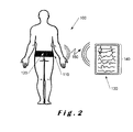
- the system 100 comprises a belt 110 in which a sensor device 120 is mounted, and a mobile computing platform 130 which displays processed waveforms 140 obtained from the sensor device 120.
- the sensor device 120 includes a transmitter which can connect to the mobile computing platform 130 by means of a wireless communications link 150.
- the belt 110 is positioned substantially on the waist of the subject with the sensor device 120 located at the lower back of the subject near to the centre of gravity or centre of mass.
- the centre of gravity or centre of mass is known to be approximately at the level of the transition between the last lumbar vertebra (known as the L5 vertebra) and the first 'vertebra' of the sacrum (known as the S1 vertebra although it may be fused with the rest of the sacrum), that is, at the L5/S1 joint.
- the sensor device 120 can be mounted in any other suitable support for retaining the sensor device as close to the centre of gravity or centre of mass of the subject as possible. In other embodiments, the positioning of the sensor device close to the centre of gravity or centre of mass of the subject may not be essential.
- the belt 110 is preferably made from a material that is flexible and comfortable for the subject when worn, particularly, if monitoring is to be performed at night during normal sleep cycles of the subject. It will readily be understood that 6-DOF acceleration data (possibly with ECG data) may be required to be collected during all phases of a subject's daily routine, for example, during resting phases (sitting or supine), active phases, spontaneous phases (with changes between resting and active phases) in addition to sleep phases. In addition, the belt 110 is adjustable so that it can fit more than one size of subject.
- the sensor device may include a self-adhesive patch which can be positioned in direct contact with the skin.
- a self-adhesive patch would be strong enough to support the sensor device so that it can be retained in place during normal daily activities.
- the sensor device 120 comprises a 6-DOF accelerometer sensor which provides 3-DOF linear information and 3-DOF angular or rotational information.
- the sensor device 120 may comprise a separate 3-DOF linear accelerometer for providing linear information in the x-, y - and z -axes and a separate angular accelerometer for providing angular or rotational information about the x-, y-, and z -axes.
- the sensor device 120 may also comprise a combination of accelerometers and gyroscopes to provide the desired number of 6-DOF waveforms 140.
- the sensor device 120 may also include at least two contact electrodes for ECG monitoring.
- the system 100 generates processed waveforms 140 which include a 6-dimensional (or six degrees of freedom (6-DOF)) MKCG signal (not shown in detail).
- the processed waveforms 140 include three degrees of freedom (3-DOF) for linear accelerations along the directions of mutually orthogonal x-, y- and z- axes, as well as 3-DOF angular accelerations or rotations as will be described in more detail below.
- the waveforms for each of the 6-DOF have the advantages that these waveforms are independent of the choice of the frame of reference and the waveforms include all components relevant to heart beat activity as described above. Therefore, using processed waveforms including a 6-DOF MKCG signal in accordance with the present invention, it is possible to provide a more accurate estimate of cardiac force and contractility than that which can be provided by conventional BCG devices having either only 1-DOF or 3-DOF.
- the mobile computing platform 130 may comprise a tablet computer, a laptop or a smart phone which is connectable to the belt using a suitable communications link 150.
- the sensor device 120 sends all its recorded data to the processing device 130 for processing and display.
- the belt 110 may include a pre-processing device which processes the signals from the sensor device 120 before transmitting the pre-processed signals to the mobile computing platform 130 for further processing.
- the mobile computing platform 130 is not needed for processing but solely for display and storage of the processed signals where a processing device is also included in the belt 110.
- the communications link 150 comprises a one-way link as shown with the belt 110 including a transmitter (not shown) connected to the sensor device 120 for transmitting measured signals to the mobile computing platform 130, the mobile computing platform including a receiver (also not shown).
- the communications link 150 may be bi-directional (not shown) and enables the sensor device to receive command signals from the mobile computing platform 130 (or some external device) and to transmit recorded signals to the mobile computing platform.
- a transceiver combined transmitter and receiver
- separate transmitters and receivers may be used with appropriate connections.
- the MKCG device can perform simultaneous recordings of ECG and 6-DOF MKCG in which both ECG electrodes and a MKCG sensor device are integrated into a single device.
- the system may optionally include a second 6-DOF sensor device placed at the apex of the heart, the sternum or on the spine between the scapulae in order to provide an SCG signal as will be described below with reference to Figure 3 .
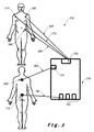
- a portable ECG/MKCG system 200 in accordance with the present invention is shown in which connections are provided between the sensors and a mobile computing platform 230.
- the system 200 comprises a sensor device 120 as described above with reference to Figure 2 positioned at the L5/S1 joint, that is, close to the centre of gravity or centre of mass of the subject.
- a mobile computing platform 230 is connected to receive signals from the sensor 120 at connections 232 via connection 125.
- the connections 232 are connected to receive data from respective ones of the accelerometers and/or gyroscopes which provide the 6-DOF waveforms (not shown).
- Sensor 260 comprises a second 6-DOF device which is positioned between the scapulae or shoulder blades of the subject in order to provide the SCG signal, the sensor 260 being connected to a terminal 234 of the portable ECG/MKCG device 230 by connection 265.
- the sensor 260 may comprise a single axis MKCG device or an accelerometer aligned with, for example, the y -axis, as described above with reference to Figure 1 c.
- Sensors 270, 280, 290 comprise ECG electrodes which are respectively positioned, as shown, on the right-side of the chest, on the lefthand side of the chest and on the hip.
- Each sensor 270, 280, 290 is connected to an ECG input terminal 236 of the ECG/MKCG device 230 by way of a respective connection 275, 285, 295.
- these electrodes are incorporated into the MKCG device itself. Output waveforms or signals from the ECG/MKCG device 230 will be described in more detail below with reference to Figure 8 .
- the connections are wired connections with the mobile processing platform being located close to the subject wearing the sensor device 120, the SCG device 260 and the sensors (ECG electrodes) 270, 280, 290.
- the connections from the SCG device 260 and from the ECG electrodes may be provided to a processor within a belt in which the sensor device 120 is mounted.
- the processor may transmit the signals to the mobile computing platform over a wired or a wireless connection.
- the signals may be recorded on an SD (Secure Digital) card for processing at a later time.
- SD Secure Digital
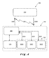
- FIG. 4 illustrates a block diagram of a portable wireless system 300 in accordance with the present invention.
- the system 300 comprises a mobile computing platform 330, such as a tablet, laptop or smart phone, which forms a processing device, which is connected to sensor devices in a belt 310 by way of a Bluetooth wireless connection 350 having both a transmit path 350T and a receive path 350R.
- Bluetooth is a trademark of the Bluetooth Special Interest Group (SIG)].
- the wireless connection 350 is not limited to Bluetooth and may comprise any suitable wireless connection that can provide a bi-directional (or one-way - transmitting only) communications link between the processor 335 and the mobile processing platform 330, for example, a suitable Wi-Fi or ZigBee link can be implemented.
- ZigBee is a trademark of the ZigBee Alliance which provides a specification for a suite of high level communication protocols using small, low-power digital radios based on an IEEE 802 standard for personal area networks. ZigBee is particularly useful in radio frequency (RF) applications where low data rates, long battery life and secure networking are required, and where periodic or intermittent data transmission or a single signal transmission is required from a sensor or other input device.
- RF radio frequency
- the belt 310 includes a Raspberry Pi processor 335 having a Bluetooth transmitter (not shown) for providing the belt-side portion of the communications link.
- Raspberry Pi is a trademark of the Raspberry Pi Foundation.
- Raspberry Pi processor Although a Raspberry Pi processor has been described, it will readily be understood that any other suitable processor may be used which meets the size requirements for positioning in the belt 310.
- the processor 335 is connected to an ECG chip or analogue-to-digital converter (ADC) 370 which acquires ECG data from ECG electrodes (not shown), digitises the analogue ECG data and makes the digitised ECG data accessible for the processor 335.
- ADC analogue-to-digital converter
- a sensor device 320 comprising three accelerometer/gyroscope modules 320X, 320Y and 320Z is also provided within the belt 310 for providing the three linear MKCG signals along respective x-, y- and z -axes and the three rotational MKCG signals around respective x-, y- and z -axes.
- bi-directional connections 325X, 325Y and 325Z are provided between respective ones of the accelerometer/gyroscope modules 320X, 320Y, 320Z.
- the bi-directional links may comprise one-way links which only pass signals from the modules to the processor 335.
- the processor 335 coordinates the acquisition of data by sampling signals provided by the sensor device 320 and the ECG chip 370.
- the ECG chip 370 may comprise an ADS1298 chip obtainable from Texas Instruments Inc. and each of the accelerometer/gyroscope modules 320X, 320Y, 320Z may comprise MPU-6000 modules obtainable from InvenSense Inc. headquartered in San Jose, California, USA. However, it will readily be appreciated that other chips and accelerometer/gyroscope modules may be used to provide the signals for providing MKCG output data.
- each of the accelerometer/gyroscope module provides a linear MKCG component along the axis with which the module is aligned and a rotational MKCG component around the axis with which the module is aligned.
- the linear MKCG component comprises a linear acceleration value which can be processed using integration techniques to derive linear velocity and linear displacement as described in more detail below.
- the rotational MKCG component comprises a rotational velocity value which can be processed using integration techniques to derive an angular displacement and using differentiation techniques to derive an angular acceleration.
- system 300 can be tailored to meet the requirement to record data from up to three accelerometers/gyroscopes modules.
- the data acquired by the processor 335 is pre-processed and stored locally on an SD card as described above.
- the pre-processed data is sent wirelessly via the wireless Bluetooth communication link 350 to the mobile computing platform 330 where the pre-processed data is further processed and displayed in a predetermined format.
- the offline or real-time analysis of data provides information on the cardiac strength of contraction.
- the processed data may be stored on the mobile computing platform 330 as well as being sent, via a further communications link (not shown), to a remote data centre (also not shown) where a data record is created and the data stored within that data record either as a reference for the subject or for matching with a previously created data record.
- FIG. 5 illustrates a flowchart 400 showing steps in a method for acquiring and processing data from the system described above with reference to Figure 4 .
- the steps are divided into device processes 410, which relate to the sensor devices (accelerometer/gyroscope modules 320X, 320Y, 320Z (and SCG module if present) and ECG electrodes) mounted within the belt 310, and, mobile computing platform processes 420 which are performed on the mobile computing platform 330 after the transfer of the data over the Bluetooth communications link 350 or on an SD card on which the data has been recorded or stored.
- device processes 410 relate to the sensor devices (accelerometer/gyroscope modules 320X, 320Y, 320Z (and SCG module if present) and ECG electrodes) mounted within the belt 310, and, mobile computing platform processes 420 which are performed on the mobile computing platform 330 after the transfer of the data over the Bluetooth communications link 350 or on an SD card on which the data has been recorded or stored.
- sensor devices accelerelerometer/g
- block 430 relates to the acquisition and digitisation of data from the sensors within the belt 310, that is, from the 6-DOF MKCG sensor, the SCG sensor and the ECG sensor. It will be appreciated that in some embodiments as described below only the MKCG sensor may be present or the MKCG sensor with one of or both the SCG sensor and the ECG sensor. There is a calibration process and sampling of the acquired data to reduce the amount of data that needs to be processed. In block 440, the calibrated and sampled data is then stored on an SD card for processing at a later date and/or transferred wirelessly to the mobile computing platform where mobile computing processes 420 are performed.
- the processes 420 performed by the mobile computing platform comprise:-
- Figure 6 illustrates a flowchart 500 of the processing steps performed by the mobile computing platform 330 in Figure 4 , either in an online mode or in an offline mode, to determine the scalar parameters, the respiratory/cardiovascular reactivity parameters and the heart rate classification as described above with reference to Figure 5 .
- the data is directly transmitted to a processor for processing, and in the offline mode, the data is stored on, an SD card as described above, for example, and stored data on the SD card is loaded onto a suitable processor at a later time for processing.
- the first step, step 505 relates to the acquisition of data from the sensors in the belt, that is, from the 6-DOF MKCG sensor, the SCG sensor and the ECG sensor. It will readily be appreciated that, although the processing of all three types of signals will be described, in some embodiments only the 6-DOF MKCG data is available, and in other embodiments, a combination of 6-DOF MKCG data with one or both of the SCG data and the ECG data.
- step 510 the MKCG, SCG and ECG signals are calibrated and filtered.
- the signals are ADC converted to convert analogue signals into digital signals.
- the calibrated data is recorded on an SD card mounted within the processor 335 for offline use as described above with reference to Figure 5 .
- the calibrated data is also transmitted wirelessly to the mobile computing platform 330 for real-time processing and subsequent display of the 6-DOF waveforms as described above. It will be appreciated that if no offline use is required, the SD card is not necessary. It will also be appreciated that the calibrated data may also be stored by the mobile computing platform 330 for offline use.
- the processing paths are effectively divided for the determination of the scalar parameters and the respiratory/cardiovascular reactivity parameters, and the heart rate classification.
- FIG. 6 there is an ECG processing path indicated by 'A', a MKCG processing path indicated by 'B' and 'C', and an SCG processing path indicated by 'D'.
- path 'A' and path 'D' may not be necessary.
- ECG analysis and event detection is performed on the acquired signals and the PQRST waveform is determined (step 515), and, from the PQRST waveform, in step 520, the R peaks and R-to-R interval time between adjacent QRS complexes, commonly known as RRi timing, are determined. Any arrhythmia present is also determined as part of step 520.
- the ECG data is processed using band-pass and notch filtering so that the heart beat or heart rate of the subject can be determined from the QRS complex of the ECG waveform as described above with reference to Figure 1 a.
- the RRi timing is used for the processing the MKCG and SCG signals as described in more detail below with reference to step 540.
- the R-peaks and arrhythmia information determined in step 520 is used as an input for heart beat classification, as will be described in more detail below with reference to step 530, and for determining ensemble averaging of the MKCG and SCG signals, as will be described in more detail below with reference to step 540.
- MKCG data where MKCG data is used for both determination of respiration, in path 'B', and MKCG-SCG analysis and detection, path 'C'.
- the respiration of the subject is determined by band-pass filtering the MKCG signals to provide cleaned up MKGC signals from which a respiratory motion signal can be derived as described below with reference to Figures 7a and 7b .
- Inspiration and expiration phases are determined in order to classify the heart beats and to be able to select some phases, for example, inspiration phases, to provide a more accurate estimate for ensemble averaging as will be described in more detail below with reference to step 540.
- the respiratory motion signal determined in step 525 is also used for the determination of MKCG amplitude modulation by respiration (MAMR) and respiratory sinus arrhythmia (RSA), indicated by arrow 525A, as will be described in more detail below with reference to step 560.
- MAMR MKCG amplitude modulation by respiration
- RSA respiratory sinus arrhythmia
- the respiratory motion signal or respiration determined in step 525 is used, with the R-peaks and arrhythmia information determined in step 520, to determine heart beat classification in step 530.
- the respiratory motion signal is effectively used to compensate for any respiratory components in the R-peaks and arrhythmia information so that the heart beat classification or heart rate or pulse of the subject can be determined.
- the MKCG and SCG analysis and event detection is performed in step 535 from MKCG data on path 'C' and the SCG data on path 'D'.
- This analysis provides an output signal which is used for ensemble averaging in step 540, as indicated by arrow 535A, and for continuous wavelet transform (CWT) analysis in step 555 as will be described in more detail below.
- CWT continuous wavelet transform
- the MKCG signal is used for CWT or time-frequency analysis in step 555.
- the output of the CWT analysis is shown in Figure 7c as will be described in more detail below.
- the output from the CWT analysis of the continuous MKCG signal,, together with the respiration frequency determined from the respiratory motion signal, indicated by arrow 525A, is used for the determination of the BAMR and RSA signals in step 560.
- RSA relates to heart beat or heart rate variability with respiration in which the R-R interval on an ECG is shortened during inspiration and lengthened during expiration.
- respiratory cardiovascular reactivity parameters are determined from the BAMR/RSA signal determined in step 560.
- the MKCG signal is used for the ensemble averaging of the MKCG and SCG signals, together with the output from step 520, that is, the heart rate or R-peaks and arrhythmia, and the output from step 530, as indicated by arrow 530A, that is, the heart beat classification, in step 540.
- the MKCG and SCG signals are processed using the heart rate from the R-peaks as a timing signal.
- the output of step 540 is used for 6-DOF analysis, in step 545, using Fourier transform analysis as will be described in more detail below.
- the output from step 545 is used to determine scalar parameters, both linear and rotational, of force, torque, kinetic energy, work and power, in step 550.
- the output from the ensemble averaging of the MKCG and SCG signals in step 540 may also be used for the determination of pulse transit time (PTT) which can be used as an indication of central or overall blood pressure, step 570.
- PTT pulse transit time
- the PTT can also be determined using the output from the MKCG-SCG analysis in step 535 together with the R-peaks and arrhythmia information determined in step 520, as indicated in dotted lines in step 580.
- a portion of a single axis MKCG waveform 600 for the y -axis comprises groups of peaks 610, 620 indicating movement in response to heart beats. It will be appreciated that only two groups 610, 620 are shown for clarity.
- a corresponding respiratory motion waveform 700 is shown which has peaks 710, 720 which substantially coincide with groups 610, 620. From Figures 7a and 7b , it will readily be appreciated that the detection of the groups of peaks 610, 620 in the MKCG waveform 600 provides the respiratory motion waveform 700 with peaks 710, 720 corresponding to maximum inspiration.
- Figure 7c illustrates the result of the CWT analysis performed in step 555.
- the darker portions, indicated at 810, 820 respectively correspond to the peaks 710, 720 and 610, 620.
- the RRi timing obtained in step 520 is used to provide beat-by-beat SCG/MKCG signals to which a Fourier transform is applied. Only a limited number of the Fourier transform components are retained by zeroing the first and upper (higher frequencies) components, and this limited number of components is used for further processing in Fourier space.
- the first integration of the linear acceleration is computed to provide linear velocity components
- the second integration of the linear acceleration is computed to provide linear displacement components.
- the angular velocity is integrated to provide the angular displacement
- the first derivative of the angular velocity provides the angular acceleration.
- An inverse Fourier transform is applied to provide the linear components of acceleration, velocity and displacement as well as the angular components of acceleration, velocity and angular displacement or rotation.
- These Fourier filtered components provide values for linear and angular acceleration, a and a respectively, linear and angular velocity, ⁇ and ⁇ respectively, and linear and angular displacement, s and ⁇ respectively, which are output on a beat-by-beat basis relative to the R waves or RRi obtained from the ECG data.
- data relating to a predetermined number of heart beats is retained and averaged to provide a local ensemble average of the estimated values of linear and angular acceleration, velocity and displacement. Typically, between 7 and 30 heart beats are retained and averaged.
- Quaternions may be used to remove cross-talk between linear and angular signals.
- the signals are compressed and filtered.
- Fourier transforms provide continuity of the derivatives of linear acceleration and angular velocity.
- data may be transmitted to the mobile computing platform as Fourier transforms and the derivatives and integrals are determined in Fourier space.
- ⁇ the torque
- I the moment of inertia of the subject which is derived using a model as described below
- ⁇ the angular acceleration
- r the radius from the axis
- K rot the rotational kinetic energy
- W rot the rotational work
- ⁇ the angular or rotational displacement
- P rot is angular power
- ⁇ the angular velocity
- the total cardiac energy can be obtained.
- summing the linear and angular or rotational work the total cardiac work can be obtained.
- the computed scalar parameters are used to identify maximum values for force, torque, kinetic energy and work in the systolic phase or contraction phase of the heart cycle. By computing a ratio between rotational values and total values, the health of the rotational contraction of the heart can be assessed. In addition, by computing ratios between systolic (contraction) and work, and, diastolic (dilation) energy and work, information relating to the operation of the atria and ventricles during refilling of the heart with blood can be provided.
- the respiratory motion signal data may be processed by performing a CWT or time-frequency analysis (not shown).
- the instantaneous breathing frequency is identified as the main wavelet component from which the start and end of inspiration and expiration phases can be determined.
- the linear and rotational data is combined to provide an accurate global cardiac function estimate.
- a combination of SCG and MKCG data in step 570 as described above, provides a measure of PTT as the SCG device is located at a different position to the MKCG sensor device as described above with respect to Figure 3 .
- PTT is a time difference between two identified events or waves, such as, the RRi timing interval as described above, or the time delay or time interval between peaks of maximum force. PTT can provide an indirect estimate of central or overall blood pressure.
- ECG data provides information relating to the timing of the R wave and the RRi; and SCG data provides information relating to the timing of heart sounds S1 (opening of the aortic valve) and S2 (closure of the aortic valve).
- PEP pre-ejection period
- the time of arrival of the MKCG shockwave can be identified from maximum force vector (or more simply, maximum acceleration) immediately following ejection of blood after S1.
- maximum force vector or more simply, maximum acceleration
- S1 The difference in timing between the maximum force vector (or maximum acceleration) and S1 provides a time interval which is similar to the blood pressure PTT.
- PTT is inversely correlated to mean central (or overall) blood pressure where a low PTT relates to high blood pressure and a high PTT relates to low blood pressure.
- the determination of PTT provides a non-intrusive indicator of blood pressure which can readily be applied to cardiac monitoring.
- current blood pressure measuring techniques utilise a device which inflates a cuff on an arm of a subject to determine the blood pressure.
- the cuff is inflated at regular time intervals (every 20 or 30 minutes, as an example). This is very uncomfortable for the patient or subject with the accompanying waking due to the inflation of the cuff.
- MKCG data in accordance with the present invention together with SCG and ECG, a solution to this problem of nighttime monitoring (as well as general monitoring) of blood pressure can be provided.
- moments of inertia I x ,I y ,I z ) of the whole body of the subject around its reference axes, that is, x : left to right, y : feet to head, z : ventro-dorsal, needs to be determined.
- the moment of inertia of whole body can be estimated using a model which only takes into account the height ( Ht ) and weight ( Wt ) of a subject as described in " Moment of inertia of whole body using an oscillating table in adolescent boys", A. Matsuo et al., J. Biomechanics, Vol. 28, No. 2, pages 219, 223, 1995 .
- Such a model implies a simple relationship independent of the age of the subject.
- a three-dimensional (3-D) relationship between the moments of inertia and the height and weight of the subject needs to be determined.
- a model was developed using published data from several studies as described in the Matsuo et al. article identified above as well as in articles by R.F. Chandler et al., "Investigation of inertial properties of the human body", US Department of Transportation Report #DOT HS-801 430, 1975 ; J.T. McConville et al., "Anthropometric relationships of body and body segment moments of inertia", Technical Report, AFAMRL-TR-80-119, 1980 ; and M. Damavandi et al., "Effect of the calculation methods on body moments of inertia estimations on individuals of different morphology", Medical Engineering & Physics, vol. 31, pages 880 to 886, 2009 .
- the developed model utilised data relating to individual values for subjects relating to their moments of inertia ( I x , I y , I z ), their height ( Ht ) and their weight ( Wt ) and to an average group value when individual data was not available.
- any suitable model can be derived for the moments of inertia calculations required for equations (5) and (6) above.
- FIG 8 illustrates measured and processed output signals obtained from a combined MKCG/ECG/SGC device in accordance with the present invention for a healthy subject.
- the first waveform 900 shows a conventional ECG waveform corresponding to ECG data similar to that described above with reference to Figure 1 a; the second waveform 910 shows a conventional SCG waveform corresponding to SCG data similar to that described above with reference to Figure 1b ; and the third waveform 920 shows three-dimensional MKCG waveforms corresponding to linear MKCG data (linear acceleration along the x-, y- and z -axes which is integrated to provide linear velocity and linear displacement along respective ones of the x-, y- and z -axes) with the IJK waves indicated similar to that described above with reference to Figure 1 c.
- Each of waveforms 900, 910, 920 effectively corresponds to measured data.
- the fourth waveform 930 shows rotational MKCG waveforms corresponding rotational MKCG data in accordance with the present invention.
- the rotational MKCG data indicates angular velocity ⁇ x , ⁇ y , ⁇ z measured by the gyroscopes in the accelerometer/gyroscope modules 320X, 320Y, 320Z described above with reference to Figure 4 .
- the angular velocity ⁇ x , ⁇ y , ⁇ z is integrated to provide the rotational acceleration ⁇ x , ⁇ y , ⁇ z with its first derivative corresponding to the angular displacement or rotation.
- the waveforms 940, 950, 960, 970 relate to data which is derived or computed from one or more combinations of the ECG data, the linear MKCG data, the SCG data, and the rotational MKCG data as described above.
- the dot-dash lines relate to linear values and the dashed lines relate to rotational values with solid lines relating to the sum of the linear and rotational values.
- Waveform 940 comprises linear force, indicated by line 940 lin , derived in accordance with equation (1) above and torque, as indicated by line 940 rot , derived in accordance with equation (4) above. Maximum values of linear force and torque are indicated at 945 lin and 945 rot respectively.
- Waveform 950 comprises total energy E t , as indicated by line 950 tot , that is, a combination of linear kinetic energy, indicated by line 950 lin , and rotational kinetic energy, indicated by line 950 rot , as derived in accordance with respective ones of equations (2) and (6) above.
- a maximum value for the total energy E t is indicated at 955 and it can readily be appreciated that this maximum value corresponds to the sum of the maximum values for linear and rotational kinetic energy as shown by the peaks under the maximum value.
- Waveform 960 comprises total work W t , as indicated by line 960 tot , that is, a combination of linear work, indicated by line 960 lin , and rotational work, as indicated by line 960 rot , as derived in accordance with respective ones of equations (3) and (7) above.
- a maximum value for the total work W t is indicated at 965 and it can readily be appreciated that this maximum value corresponds to the sum of the maximum values for linear and rotational work as shown by the peaks under the maximum value.
- Waveform 970 comprises total cardiac power P t , as indicated by line 970 tot , that is, a combination of cardiac linear power, indicated by line 970 lin , and cardiac rotational power, as indicated by line 970 rot , as derived in accordance with respective ones of equations (4) and (8) above.
- a maximum value for the total energy P t is indicated at 975 and it can readily be appreciated that this maximum value corresponds to the sum of the maximum values for cardiac linear and rotational power as shown by the peaks under the maximum value.
- the ratios of rotational energy E r to total energy E t , E r / E t , of rotational work W r to total work W t , W r / W t , and of rotational power P r to total power P t , P r / P t can be shown to be in a range of between 60% and 85%. From the waveforms shown in Figure 8 , these ratios were determined to be 66.0%, 64.6% and 61.6% respectively. In another set of data (not shown), these values were found to be 84.6%, 84.0% and 81.8% respectively. This clearly shows that, by determining rotational MKCG data, additional information relating to the efficiency of the heart can be determined.
- 6-DOF MKCG data Whilst the present invention has been described using combinations of ECG data, 6-DOF MKCG data and SCG data, it will readily be appreciated that 6-DOF MKCG data can be used on its own.
- a miniaturised wearable MKCG device intended for use by the general public, records only 6-DOF MKCG data.
- the device includes three accelerometer/gyroscope modules, as described above with reference to Figure 4 , and a processor similar to the processor 335 described above with reference to Figure 4 .
- the device may include a removable SD card for storing data for subsequent processing and/or the data may be transmitted to a mobile computing platform such as a smart phone, tablet computer, laptop etc.
- the processor also includes a communications link, preferably a Bluetooth link. It will readily be understood that other communications links may be used as described above.
- All components of the MKCG device are included on a single system on a chip (SOC) which is small and can readily be incorporated into a belt as described above with reference to Figure 2 , or any other suitable support that locates the MKCG device at the L5/S1 joint or centre of mass (or gravity) of a user of the device.
- SOC system on a chip
- an SCG sensor for example, another MKCG device, may also be provided which is locatable at a suitable position on the body for the determination of PTT information providing indications of blood pressure.
- Such an SCG sensor is configured to transmit signals, via a suitable communications link, to the SOC located close to the centre of mass or centre of gravity of the subject for processing to provide the PTT information as described above.
- a wearable MKCG/ECG device intended for use for medical monitoring, comprises a 6-DOF MKCG sensor (accelerometer/gyroscope modules 320X, 320Y, 320Z as described with reference to Figure 4 ) with two ECG electrodes mounted within a single housing.
- the housing is attachable to the skin of the user at the L5/S1 joint or centre of mass (or gravity) of a user of the device.
- the device includes a transmitter for transmitting MKCG data and ECG data to a remote monitoring station.
- the remote monitoring station may be a mobile computing platform as described above with a suitable communications link between the MKCG/ECG device and the mobile computing platform.
- the remote monitoring station may be located at a hospital or doctor's office and is connected to receive data transmitted from MKCG/ECG device either directly from the device, via an internet connection, or from the mobile computing platform also via an internet, the mobile computing platform receiving MKCG/ECG data from the MKCG/ECG device using a Bluetooth connection as described above.
- the remote monitoring station may comprise a server connected to the internet or to a cloud-based application.
- a portable MKCG device intended for use in research, comprises a 6-DOF MKCG sensor (accelerometer/gyroscope modules 320X, 320Y, 320Z as described with reference to Figure 4 ), an SCG sensor and an ECG sensor.
- the MKCG sensor is positioned at the L5/S1 joint or centre of mass as described above, the SCG sensor is positioned on the chest at the apex of the heart, and the ECG sensor is positioned at a location remote from the heart, for example, on an arm or a leg.
Abstract
Described herein is a multi-dimensional kineticardiography device (300) which comprises a sensor (320) having three accelerometer/gyroscope modules (320X, 320Y, 320Z) mounted in a support which positions it at the centre of mass of a subject whose cardiac function is to be measured. The sensor (320) outputs six degrees of freedom data as linear acceleration along and rotational or angular velocity about x-, y- and z-axes. The sensor (320) is connected to a processor (335) for transmitting the kineticardiography data obtained from the sensor (320) and the electrocardiography data to a mobile computing platform (330), via Bluetooth (350), for further processing and display. An electrocardiography data chip (370) is also present for digitising the electrocardiography data for further processing. The kineticardiography data provides rotational information which can be used to determine torque, rotational kinetic energy, rotational work and rotational cardiac power which have been shown to contribute at least 60% of the total kinetic energy, work and cardiac power values.
Description
- The present invention relates to improvements in or relating to heart monitoring and is more particularly, although not exclusively, concerned with multi-dimensional kineticardiography.
- Monitoring the cardiac function is essential for the health status assessment of a subject. Non-invasive and accurate hemodynamic monitoring has been a constant subject of attention in the field of cardiology. Several non-invasive methods are known to provide information on the cardiac function.
- The electrocardiogram (ECG) provides information about the electric activity related to the myocardium contraction. It is passively recorded via the use of electrodes placed on the chest of the subject, and, proper amplification of this signal. It provides mostly information on the timings and propagation of the contraction of the four heart cavities. The ECG provides what is often termed as a "PQRSTU" waveform, but in most cases, only the "PQRS" portion is considered.
- The phonocardiogram (PCG) is a technique based on the recording of heart sounds. It provides the determination of the timing of opening and closure of the aortic valve. It is usually combined with an ECG to provide a more detailed evaluation of the health of the heart of an individual.
- The impedance-cardiogram (ICG) is an active technique usually combined with the ECG in which a small electrical current is generated through the thorax of the subject being assessed, electrodes being placed on the neck and the base of the thorax. The changes in thoracic impedance are monitored via a second set of electrodes placed in between the first set. By the use of model equations, the measured impedance signal, which is influenced by the content of fluid in the thorax and its variations, can provide additional information to that provided by the ECG alone. For example, the volume of blood ejected within one cardiac cycle, termed the stroke volume, may be determined in this way.
- The echocardiogram is an imaging technique which is based on Doppler ultrasound technology. An ultrasound probe is placed in contact with the chest of the subject and properly oriented by a trained operator to produce 2D or 3D images of the cardiac chambers. It is one of the "gold standard" techniques to provide an overall cardiac health assessment and is usually combined with an ECG. Echocardiography can provide information relating to the volume of the cardiac chambers, blood flow, etc. Tissue Doppler imaging and speckle tracking techniques further permit the determination of the cardiac contractility, that is, the efficiency of the cardiac contraction, which is a crucial parameter for assessing cardiac health.
- Cardiovascular magnetic resonance imaging (CMR), sometimes known as cardiac MRI, is a medical imaging technology for the non-invasive assessment of the cardiac function and structure of the cardiovascular system. This is the most advanced and expansive type of cardiac assessment which is performed in an MRI device with the assistance of a team of specially-trained operators. Cardiac MRI can provide similar information to echocardiography and much more.
- Each of these techniques is well known but present some limitations, for example:
- ECG is the only technique that can currently be implemented in a wearable/portable monitoring system which can be used remotely without the help of a trained operator. However, ECG technology provides only limited information relating to the electrical activity of the heart, and, there is no information on cardiac contractility and blood flow. Furthermore, sticky electrodes need to be used which can become detached from the skin of the subject or which can be uncomfortable to use, especially for long term monitoring such as for night recordings.
- Both PCG and ICG are highly sensitive to noise and artefacts. ICG is influenced by movements of the subject, and, because its use requires additional electrodes, remote or home monitoring is not a practical possibility.
- Echocardiography and cardiac MRI are the only existing methods to provide detailed information on cardiac contractility. However, due to the complexity of the systems for these techniques, both techniques require specially-trained operators. This make it impractical to develop portable devices.
- In parallel with the methods described above, other well-known techniques based on the recording of vibration, acceleration, and displacement of motion of the body of the subject which occurs as a result of the heart beat or heart rate. These well-known techniques are based on Newton's laws of motion and the principle of action-reaction. A broad spectrum of terminology is used to describe the output of such techniques, for example, ballistocardiogram, seismocardiogram, kinetocardiogram, apexcardiogram, mechanocardiogram, etc., with the corresponding techniques being described as ballistocardiography, seismocardiography, kinetocardiography, apexcardiography, mechanocardiography, etc.
- Ballistocardiography, the most common, is based on sensing the ballistic forces, namely, recoil and impact, associated with cardiac contraction and ejection of blood on the body of the subject being monitored. This technique was developed in the 1950s and 1960s with the aim of providing information on cardiac force of contraction and stroke volume. The main advantages over the other non-invasive cardiac monitoring techniques are: they make use of accelerometers to record the body movements (which removes the need for electrodes for electric contact with the body which is uncomfortable and a potential risk of electric shock to the subject); they provide direct information of the force of the contraction and the heart contractility which are essential parameters in cardiology; they do not require a specially-trained operator for use; and the devices for ballistocardiography can be miniaturized and automated.
- Furthermore, for health monitoring at home and in remote locations, it is important that the device be as unnoticeable as possible. This is especially important when the monitoring is carried out at home where vital sign monitoring must be unobtrusive and as convenient and invisible as possible, in order to not interfere with the comfort of the subject. This is even more important for sleep monitoring where the device should not interfere with the quality of sleep.
-
WO-A-2010/145009 describes a method and apparatus for obtaining and processing ballistocardiography data to determine a physiological condition of a subject in which data indicative of heart motion of the subject is measured using a sensor device, such as, a three-axis accelerometer which provides three-dimensional data, which can be aggregated. A sensor device mounted in a housing is positioned on the chest of the subject and is connected to a computing device via a communications link. Accelerometer signals in three-dimensions are spatially aggregated to a lower dimension, for example, one- or two-dimensions to provide quick and efficient processing. - Whilst such a method and apparatus provides three-dimensional data, this is limited to three linear axes which are mutually perpendicular or orthogonal.
- Whilst the use of ballistocardiography is partly successful, it tends to be mainly used in the field of fundamental research and is not widely used in medical practice. This is mainly due, on one hand, to the emergence of echocardiography, and, on the hand, to lack of standards and poor reliability of a method which is mostly based on a single or three-axis recording.
- It is an object of the present invention to provide a multi-dimensional kineticardiography system which is an improvement of former ballistocardiography systems and produces accurate and detailed information about vital signs, such as cardiac and respiratory activity of a living body.
- It is another object of the present invention to provide passive, non-invasive, non-intrusive and autonomous methods for personal remote health monitoring.
- It is yet another object of the present invention to provide a multi-dimensional kineticardiography system which provides output data which is indicative of rotational contraction health of the heart.
- It is a further object of the present invention to provide a portable or wearable multi-dimensional kineticardiography system.
- In accordance with one aspect of the present invention, there is provided a multi-dimensional kineticardiography system comprising:-
- a kineticardiography sensor operable for producing kineticardiography sensor signals indicative of movement in response to heart beat in six dimensions; and
- at least one processor configured to be connected to said kineticardiography sensor for receiving six-dimensional kineticardiography sensor signals therefrom and being operable for processing said six-dimensional kineticardiography sensor signals to generate at least one kineticardiogram in accordance therewith.
- By being able to generate kineticardiography signals in six dimensions or having six degrees of freedom, it is possible to provide accurate and detailed information relating to heart health. This is of particular relevance to rotational components derived as three of the six dimensions or degrees of freedom (where the other three dimensions or degrees of freedom correspond to linear components), and where the ratios of rotational kinetic energy, rotational cardiac work and rotational cardiac power to respective ones of the total kinetic energy (linear and rotational), total cardiac work (linear and rotational) and total cardiac power (linear and rotational) tend to be at least between 60% and 85% for a healthy subject, and therefore the rotational components play a considerable part in determining the health of a subject.
- Indeed, when considering single axis ballistocardiography, the analysis is dependent of the choice of axis. Whilst three-axis or three-dimensional ballistocardiography may be axis independent, rotational components of movement of the heart and as well as blood through the heart cannot be determined from such information. Kineticardiography or kineticardiogram recordings or displays take into account all contributions from the movement of the heart and blood into the main arteries, and more particularly the rotational components of those movements.
- In addition, there are recent findings in cardiology demonstrating that, in a pathological situation, these rotational components (measured through echo two-dimensional speckle tracking imaging) are affected at an earlier stage of the pathology, and therefore multi-dimensional kineticardiography in accordance with the present invention, that is, considering both linear and rotational components, has a crucial technical advantage over other single axis or even three-dimensional or three axes ballistocardiography devices or systems as these will be less sensitive for the detection of a progressing pathological state.
- Preferably, said kineticardiography sensor comprises a plurality of accelerometer modules. Each accelerometer module may comprise an accelerometer element and a gyroscopic element.
- In the simplest system comprising only kineticardiography sensors, respiratory motion signals may be determined from said kineticardiography sensor signals which can be used for the evaluation of other cardiovascular reactivity parameters.
- In one embodiment, a seismocardiography sensor is provided which is operable for generating seismocardiography sensor signals in response to said heart beat, said at least one processor being operable for processing said seismocardiography sensor signals in conjunction with said kineticardiography sensor signals.
- In this way, a pulse transit time signal may be generated which is indicative of blood pressure. This has the advantage of being non-intrusive as the subject being monitored no longer needs to wear a restrictive cuff which is inflated at regular intervals for blood pressure monitoring, and blood pressure monitoring at night becomes more comfortable.
- In another embodiment, at least one electrocardiography sensor is included which is operable for generating electrical signals corresponding to said heart beat, said at least one processor being operable for processing said electrocardiography signals in conjunction with said kineticardiography signals.
- Whilst the electrical signals are processed to generate an electrocardiogram, they can also be used in conjunction with the kineticardiography signals for determining other aspects relating to health of a subject being monitored.
- In addition, the electrical signals may be used as timing signals for the kineticardiography and seismocardiography signals.
- Whilst it will be understood that the kineticardiography system of the present invention may be a self-contained device which stores data on an SD card, it will be appreciated that the kineticardiography system may be connectable to a more powerful external processor or computing platform, the processor within the device pre-processing the signals for transmission to external processor or computing platform. Ideally, such an external processor or computing platform is connectable to said at least one processor by a communications link.
- In a further embodiment, the system comprises a housing in which at least said kineticardiography sensor is housed, the housing being configured to be positioned close to the centre of mass of a subject. This provides a compact and at least portable system or device.
- In another embodiment, the housing may comprise a wearable belt. This has the advantage of providing a cardiac wearable monitoring solution which offers an expanded view on cardiac function providing information, such as, cardiac contractility. This is in contrast to conventional non-wearable techniques, such as, echocardiography and/or cardiac magnetic resonance imaging.
- In accordance with another aspect of the present invention, there is provided a method of processing data from a multi-dimensional kineticardiography system comprising a kineticardiography sensor operable for producing kineticardiography sensor signals indicative of movement in response to heart beat in six dimensions, the method comprising processing said kineticardiography sensor signals to provide linear kineticardiography data along three orthogonal axes and rotational kineticardiography data about said three orthogonal axes.
- As described above, by having six-dimensional data instead of one- or at the most three-dimensional data, other heart parameters can be determined, for example, rotational contraction health.
- Respiratory motion signals may be generated from the kineticardiography sensor signals. Such signals may be used to compensate for movement of a subject due to inspiration and expiration thereby providing more accurate data.
- Fourier transform analysis may be performed on said kineticardiography sensor signals to derive linear velocity and linear displacement vectors from linear acceleration vectors along each of said three orthogonal axes, and angular acceleration and angular displacement vectors from angular velocity vectors about each of said three orthogonal axes.
- Scalar parameters may be derived which relate to at least force, linear kinetic energy, linear cardiac work and linear cardiac power from linear acceleration, linear velocity and linear displacement vectors and scalar parameters of torque, rotational kinetic energy, rotational cardiac work and rotational cardiac power from angular acceleration, angular velocity and angular displacement vectors.
- Indicators of rotational contraction health may derived from at least one of: ratio of rotational kinetic energy to total kinetic energy, ration of rotational cardiac work to total cardiac work, and ratio of rotational cardiac power to total cardiac power where total kinetic energy, cardiac work and cardiac power each comprises a summation of associated linear and rotational values.
- In this sense, the present invention has the capability of providing similar information, although not exactly the same as conventional techniques (because the information is determined indirectly), but with an automated small wearable non-invasive form factor.
- In summary, in accordance with embodiments of the present invention, a multi-dimensional kineticardiography device is provided which is non-intrusive whilst offering cardiac contraction estimations similar to those provided by echocardiography or cardiac magnetic resonance imaging. However, such techniques require bulky equipment, are expensive and need to be operated by trained or specialised personnel. Typically, these techniques cannot be provided everywhere, especially in remote locations, and a multi-dimensional kineticardiography device in accordance with the present invention enables cardiac contraction estimations to be provided with less bulky equipment which is considerably less expensive and do not require a trained or specialised personnel.
- For a better understanding of the present invention, reference will now be made, by way of example, to the accompanying drawings in which:-
-
Figures 1 a to 1 c respectively illustrates portions of conventional electrocardiogram, seismocardiogram and ballistocardiogram waveforms; -
Figure 2 illustrates a multi-dimensional kineticardiography system in accordance with the present invention; -
Figure 3 illustrates one embodiment of a multi-dimensional kineticardiography system in accordance with the present invention; -
Figure 4 illustrates an implementation of the multi-dimensional kineticardiography system ofFigure 3 ; -
Figure 5 illustrates a flowchart of processing performed in the multi-dimensional kineticardiography system ofFigure 6 ; -
Figure 6 illustrates a flowchart showing the processing steps of the kineticardiography (kineticardiogram), seismocardiography (seismocardiogram) and electrocardiography (electrocardiogram) signals to provide heart beat classification, scalar parameters and respiratory cardiovascular reactivity parameters; -
Figures 7a to 7c respectively illustrate a kineticardiography waveform; a respiratory motion waveform and a continuous wavelet transform; and -
Figure 8 illustrates output waveforms obtained using the multi-dimensional kineticardiography system ofFigure 4 . - The present invention will be described with respect to particular embodiments and with reference to certain drawings but the invention is not limited thereto. The drawings described are only schematic and are non-limiting. In the drawings, the size of some of the elements may be exaggerated and not drawn on scale for illustrative purposes.
- The present invention relates to the field of physiological monitoring instrumentation and methods for providing accurate and detailed information about vital signs, such as cardiac and respiratory activity, of a living body by use of at least one accelerometer placed in contact with the skin.
- The present invention relates further to the field of passive, non-invasive, non-intrusive and autonomous methods for personal remote health monitoring which obviates the need to visit medical personnel when a check needs to be made.
- A multi-dimensional kineticardiography device will be described below which is easy and comfortable to wear which provides information on vital signs of a living (human) body.
- The terms "multi-dimensional kineticardiography" and "kineticardiography" as used herein refer to an advanced version of ballistocardiography in accordance with the present invention as will be described in more detail below. The term "multi-dimensional kineticardiography" may be abbreviated to "MKCG".
- The term "kineticardiogram" as used herein refers to an output from a multi-dimensional kineticardiography (or kineticardiography) device.
- The term "linear" as used herein refers to values or vectors (values with directionality) of acceleration, velocity and displacement measured along or derived with respect to at least one of three orthogonal axes, typically, along the x-, y- and z-axes.
- The terms "angular" and "rotational" as used herein refer to values or vectors of acceleration, velocity and displacement measured about or derived with respect to at least one of three orthogonal axes, typically, about one of the x-, y- and z-axes.
-
Figure 1a illustrates a typical electrocardiogram (ECG)waveform 10 that consists of a P wave, a QRS complex and a T wave, the QRS complex having the highest frequency but is of relatively short duration. These waveforms from an ECG (PQRST) are related to the recording of the electrical activity of the myocardium. As is readily understood, ECG only records the normal or abnormal propagation of electrical excitation of the cardiac muscle which generate the blood ejection. These waves do not reflect the efficiency of the contraction. -
Figure 1b illustrates a seismocardiogram (SCG)waveform 20 which illustrates the timing of heart sounds S1 (opening of the aortic valve) and S2 (closure of the aortic valve). By determining the timing of S1 and S2, it is possible to determine the pre-ejection period (PEP) from the difference between the timing of S1 and the R peak of the ECG (if that information is available), and the left ventricular ejection time from the difference between the timing of S1 and S2. -
Figure 1c illustrates a typical one-dimensional ballistocardiogram (BCG) waveform 30 that consists of a HIJK complex comprising an H wave, an I wave, a J wave and a K wave components of a single axis BCG, for example, along the y-axis, from feet to head. There is no correspondence between the PQRST and the HIJK waves. - The main difference between an ECG waveform and a BCG waveform is that the HIJK waveform amplitudes are related to stroke volume (SV), cardiac output (CO) and cardiac contractility (CC). Therefore, they offer important complementary information to that provided by the ECG waveform. This information on SV, CO or CC usually requires the use of the following standard techniques: echocardiography for SV and CO; echo-2D-speckle tracking imaging for CC; and/or cardiac MRI for SV, CO and CC. As described above, none of these techniques are portable or readily useable by an unskilled person.
- A heart comprises four chambers, namely, a left atrium, a right atrium, a left ventricle and a right ventricle with the left atrium being connected to the left ventricle by the mitral valve and the right atrium being connected to the right ventricle by the tricuspid valve. The right atrium is connected to the superior vena cava (supplying blood from the upper part of the body) and to the inferior vena cava (supplying blood from the lower part of the body).
- The tricuspid valve opens by the simultaneous contraction of the right atrium myocardium and the right ventricular papillary muscles to allow blood flow from the right atrium to the right ventricle, and, closes when the right ventricular papillary muscles relax. When the myocardium of the right ventricle contracts, blood is forced from the right ventricle through the pulmonary valve into the pulmonary artery which delivers blood to the lungs for re-oxygenation.
- When the ventricles are filled with blood and the tricuspid and mitral valves are closed, the ventricles undergo an isovolumetric contraction which marks a first phase of systole. A second phase of systole sends blood from the left ventricle to the aorta and from the right ventricle to the lungs. The atria and ventricles therefore contract in an alternating sequence, for example, a first contraction phase for the atria and a second contraction phase for the ventricles. The left and right atria feed blood simultaneously into respective ventricles during the first contraction phase, and, the left and right ventricles feed blood simultaneously into the aorta and pulmonary vein respectively in the second contraction phase.
- Diastole (dilation) is the period during which the heart is refilled with blood following systole (contraction). Ventricular diastole is the period during which the ventricles are filling and relaxing and atrial diastole is the period during which the atria are relaxing.
- The oxygenated blood is returned to the left atrium via the pulmonary vein, and, flows from the left atrium to the left ventricle when the mitral valve is opened by the simultaneous contraction of the left atrium myocardium and the left ventricular papillary muscles. By this opening of the mitral valve, the oxygenated blood is then forced out of the left ventricle through the aortic valve and into the aorta and into the peripheral vascular system of the body. The mitral valve closes when the left ventricular papillary muscles relax.
- As a result of this opening and closing of valves in the heart, there is a substantially regular rhythmic beat, commonly termed "heart beat". A heart beat comprises three stages, namely, atrial systole, ventricular systole and complete cardiac diastole. Atrial systole being the period of contraction of the heart muscles of the left and right atria, with both atria contracting simultaneously with the left and right ventricular papillary muscles to open the tricuspid and mitral valves.
- Atrial systole is the electrical activity that causes the heart to beat through stimulation of the muscles thereof, and begins at the sinoatrial node located in the right atrium just below the opening to the superior vena cava. Electrical depolarisation travels in a wave downwards, leftwards and posteriorly through both atria depolarising each atrial muscle cell in turn. This propagation of electrical charge is shown as the P wave in an ECG waveform as shown in
Figure 1 a. - This P wave is followed by a mechanical contraction of the atria which is detected on a BCG waveform as an impact and recoil as described above. As the right and left atria begin to contract, there is an initial high velocity flow of blood into the respective ones of the right and left ventricles, and, continued atrial contraction as the tricuspid valve begins to close forces an additional lower velocity flow of blood into the right and left ventricles. This additional lower velocity flow of blood is termed the "atrial kick". After the atria are emptied, the tricuspid and mitral valves close.
- Ventricular systole is the contraction of the muscles of the left and right ventricles and is shown as the QRS complex in the ECG waveform shown in
Figure 1 a with the downward Q wave being caused by the downward flow of depolarisation through the septum along a group of cells called the "bundle of His". The R wave is caused by depolarisation of the ventricular muscle tissue and the S wave is produced by depolarisation of the heart tissue between the atria and the ventricles. As the depolarisation travels down the septum that throughout the ventricular myocardia, the atria and sinoatrial node depolarise. The closing of the tricuspid and mitral valves form the start of the ventricular systole and generate the first part of the sound made by the heart as it beats, formally known as the "first heart tone". - As the electrical depolarisation of the ventricular myocardia peaks, the AV septum separating the right and left ventricles contracts causing an impact and associated recoil in the BCG waveform. Ventricular contraction forces blood from the right ventricle into the pulmonary artery through the pulmonary valve and from the left ventricle into the aorta through the aortic valve under very high velocity. As the left ventricle empties, its pressure falls below the pressure in the aorta and the aortic valve closes. Similarly, for the right ventricle as it empties, its pressure falls below the pressure in the pulmonary artery and the pulmonary valve closes. This closure of the aortic and pulmonary valves causes the "second heart tone". As the AV septum relaxes and moves upwards, the ventricular myocardia is re-polarised giving rise to the T wave in the ECG.
- Cardiac diastole (including both atrial and ventricular diastole corresponding respectively to when the atria and ventricles are relaxing) is the period of time when the heart relaxes after contraction and is refilled with circulating blood, deoxygenated blood into the right atrium and oxygenated blood into the left atrium. Refilling of the atria is indicated by the U wave following the T wave in the ECG (not shown in
Figure 1 a) . As the left and right atria are filled to their respective maximum capacity, the reflux of blood against the tricuspid and mitral valves causes an impact in the BCG waveform. - Cardiac arrhythmia, also known as cardiac dysrhythmia or irregular heart beat, is a group of conditions in which the normal heart beat is irregular, that is, either too fast or too slow. Arrhythmias are due to problems with the electrical conduction system of the heart and can readily be detected by ECG analysis. Generally, a normal heart beat for adults is in between 60 and 100 beats per minute with a normal heart beat above 100 beats per minute and a normal heart beat below 60 beats per minute being known as tachycardia and bradycardia respectively. Whilst many arrhythmias have no symptoms, when symptoms are present these may include palpitations or pauses between heart beats. More serious symptoms may include one or more of light-headedness, fainting or passing out, shortness of breath, and chest pain. While most arrhythmias tend not to be serious, others may predispose a subject to complications, such as, stroke or heart failure. Other arrhythmias may result in cardiac arrest.
- Athletes tend to have lower than normal heart beats, typically well below 60 beats per minute, which is considered to be normal for such subjects.
- There are four main types of arrhythmias: extra beats, supraventricular tachycardias, ventricular arrhythmias, and bradyarrhythmias. Extra beats include premature atrial and premature ventricular contractions. Supraventricular tachycardias include atrial fibrillation, atrial flutter, and paroxysmal supraventricular tachycardia. Ventricular arrhythmias include ventricular fibrillation and ventricular tachycardia.
- Arrhythmias may occur in children but the normal range for the heart rate is different and depends on age.
- Turning now to
Figure 2 , aMKCG system 100 in accordance with the present invention is shown. Thesystem 100 comprises abelt 110 in which asensor device 120 is mounted, and amobile computing platform 130 which displays processedwaveforms 140 obtained from thesensor device 120. Thesensor device 120 includes a transmitter which can connect to themobile computing platform 130 by means of a wireless communications link 150. - As shown, the
belt 110 is positioned substantially on the waist of the subject with thesensor device 120 located at the lower back of the subject near to the centre of gravity or centre of mass. The centre of gravity or centre of mass is known to be approximately at the level of the transition between the last lumbar vertebra (known as the L5 vertebra) and the first 'vertebra' of the sacrum (known as the S1 vertebra although it may be fused with the rest of the sacrum), that is, at the L5/S1 joint. - Although the positioning of the
belt 110, and hence the positioning of thesensor device 120, is shown in one position, it will readily be appreciated that thesensor device 120 can be mounted in any other suitable support for retaining the sensor device as close to the centre of gravity or centre of mass of the subject as possible. In other embodiments, the positioning of the sensor device close to the centre of gravity or centre of mass of the subject may not be essential. - Naturally, it will readily be appreciated that the
belt 110 is preferably made from a material that is flexible and comfortable for the subject when worn, particularly, if monitoring is to be performed at night during normal sleep cycles of the subject. It will readily be understood that 6-DOF acceleration data (possibly with ECG data) may be required to be collected during all phases of a subject's daily routine, for example, during resting phases (sitting or supine), active phases, spontaneous phases (with changes between resting and active phases) in addition to sleep phases. In addition, thebelt 110 is adjustable so that it can fit more than one size of subject. - Naturally, it is not essential to have a belt in which the sensor device is mounted. The sensor device may include a self-adhesive patch which can be positioned in direct contact with the skin. Such a self-adhesive patch would be strong enough to support the sensor device so that it can be retained in place during normal daily activities.
- In one embodiment, the
sensor device 120 comprises a 6-DOF accelerometer sensor which provides 3-DOF linear information and 3-DOF angular or rotational information. In another embodiment, thesensor device 120 may comprise a separate 3-DOF linear accelerometer for providing linear information in the x-, y- and z-axes and a separate angular accelerometer for providing angular or rotational information about the x-, y-, and z-axes. In another embodiment, thesensor device 120 may also comprise a combination of accelerometers and gyroscopes to provide the desired number of 6-DOF waveforms 140. In yet another embodiment, thesensor device 120 may also include at least two contact electrodes for ECG monitoring. - As will be described in more detail below, the
system 100 generates processedwaveforms 140 which include a 6-dimensional (or six degrees of freedom (6-DOF)) MKCG signal (not shown in detail). The processedwaveforms 140 include three degrees of freedom (3-DOF) for linear accelerations along the directions of mutually orthogonal x-, y- and z-axes, as well as 3-DOF angular accelerations or rotations as will be described in more detail below. - By having a 6-DOF MKCG signal within the processed waveforms, the waveforms for each of the 6-DOF have the advantages that these waveforms are independent of the choice of the frame of reference and the waveforms include all components relevant to heart beat activity as described above. Therefore, using processed waveforms including a 6-DOF MKCG signal in accordance with the present invention, it is possible to provide a more accurate estimate of cardiac force and contractility than that which can be provided by conventional BCG devices having either only 1-DOF or 3-DOF.
- The
mobile computing platform 130 may comprise a tablet computer, a laptop or a smart phone which is connectable to the belt using a suitable communications link 150. In the illustrated embodiment, thesensor device 120 sends all its recorded data to theprocessing device 130 for processing and display. In another embodiment (not shown), thebelt 110 may include a pre-processing device which processes the signals from thesensor device 120 before transmitting the pre-processed signals to themobile computing platform 130 for further processing. In a further embodiment, themobile computing platform 130 is not needed for processing but solely for display and storage of the processed signals where a processing device is also included in thebelt 110. - The communications link 150 comprises a one-way link as shown with the
belt 110 including a transmitter (not shown) connected to thesensor device 120 for transmitting measured signals to themobile computing platform 130, the mobile computing platform including a receiver (also not shown). In another embodiment, the communications link 150 may be bi-directional (not shown) and enables the sensor device to receive command signals from the mobile computing platform 130 (or some external device) and to transmit recorded signals to the mobile computing platform. In this case, a transceiver (combined transmitter and receiver) is provided both in thebelt 110 and in themobile computing platform 130. Alternatively, separate transmitters and receivers may be used with appropriate connections. - Although not shown in
Figure 2 , in one embodiment of the present invention, the MKCG device can perform simultaneous recordings of ECG and 6-DOF MKCG in which both ECG electrodes and a MKCG sensor device are integrated into a single device. - The system may optionally include a second 6-DOF sensor device placed at the apex of the heart, the sternum or on the spine between the scapulae in order to provide an SCG signal as will be described below with reference to
Figure 3 . - In
Figure 3 , a portable ECG/MKCG system 200 in accordance with the present invention is shown in which connections are provided between the sensors and amobile computing platform 230. Thesystem 200 comprises asensor device 120 as described above with reference toFigure 2 positioned at the L5/S1 joint, that is, close to the centre of gravity or centre of mass of the subject. Amobile computing platform 230 is connected to receive signals from thesensor 120 atconnections 232 viaconnection 125. Although not shown, it will be understood that theconnections 232 are connected to receive data from respective ones of the accelerometers and/or gyroscopes which provide the 6-DOF waveforms (not shown). -
Additional sensors MKCG system 200 and which also connect to theprocessing device 230 as shown.Sensor 260 comprises a second 6-DOF device which is positioned between the scapulae or shoulder blades of the subject in order to provide the SCG signal, thesensor 260 being connected to aterminal 234 of the portable ECG/MKCG device 230 byconnection 265. In an alternative embodiment, thesensor 260 may comprise a single axis MKCG device or an accelerometer aligned with, for example, the y-axis, as described above with reference toFigure 1 c. -
Sensors sensor ECG input terminal 236 of the ECG/MKCG device 230 by way of arespective connection MKCG device 230, in a preferred embodiment (not shown), these electrodes are incorporated into the MKCG device itself. Output waveforms or signals from the ECG/MKCG device 230 will be described in more detail below with reference toFigure 8 . - In the embodiment shown in
Figure 3 , the connections are wired connections with the mobile processing platform being located close to the subject wearing thesensor device 120, theSCG device 260 and the sensors (ECG electrodes) 270, 280, 290. However, it will readily be appreciated that the connections from theSCG device 260 and from the ECG electrodes may be provided to a processor within a belt in which thesensor device 120 is mounted. In this case, the processor may transmit the signals to the mobile computing platform over a wired or a wireless connection. In addition, the signals may be recorded on an SD (Secure Digital) card for processing at a later time. -
Figure 4 illustrates a block diagram of aportable wireless system 300 in accordance with the present invention. Thesystem 300 comprises amobile computing platform 330, such as a tablet, laptop or smart phone, which forms a processing device, which is connected to sensor devices in abelt 310 by way of aBluetooth wireless connection 350 having both a transmitpath 350T and a receivepath 350R. [Bluetooth is a trademark of the Bluetooth Special Interest Group (SIG)]. - It will be appreciated that the
wireless connection 350 is not limited to Bluetooth and may comprise any suitable wireless connection that can provide a bi-directional (or one-way - transmitting only) communications link between theprocessor 335 and themobile processing platform 330, for example, a suitable Wi-Fi or ZigBee link can be implemented. - ZigBee is a trademark of the ZigBee Alliance which provides a specification for a suite of high level communication protocols using small, low-power digital radios based on an IEEE 802 standard for personal area networks. ZigBee is particularly useful in radio frequency (RF) applications where low data rates, long battery life and secure networking are required, and where periodic or intermittent data transmission or a single signal transmission is required from a sensor or other input device.
- In this embodiment, the
belt 310 includes aRaspberry Pi processor 335 having a Bluetooth transmitter (not shown) for providing the belt-side portion of the communications link. [Raspberry Pi is a trademark of the Raspberry Pi Foundation.] - Although a Raspberry Pi processor has been described, it will readily be understood that any other suitable processor may be used which meets the size requirements for positioning in the
belt 310. - The
processor 335 is connected to an ECG chip or analogue-to-digital converter (ADC) 370 which acquires ECG data from ECG electrodes (not shown), digitises the analogue ECG data and makes the digitised ECG data accessible for theprocessor 335. - A
sensor device 320 comprising three accelerometer/gyroscope modules belt 310 for providing the three linear MKCG signals along respective x-, y- and z-axes and the three rotational MKCG signals around respective x-, y- and z-axes. As shown inFigure 4 ,bi-directional connections gyroscope modules processor 335. - The
processor 335 coordinates the acquisition of data by sampling signals provided by thesensor device 320 and theECG chip 370. - The
ECG chip 370 may comprise an ADS1298 chip obtainable from Texas Instruments Inc. and each of the accelerometer/gyroscope modules - As described above, each of the accelerometer/gyroscope module provides a linear MKCG component along the axis with which the module is aligned and a rotational MKCG component around the axis with which the module is aligned. The linear MKCG component comprises a linear acceleration value which can be processed using integration techniques to derive linear velocity and linear displacement as described in more detail below. The rotational MKCG component comprises a rotational velocity value which can be processed using integration techniques to derive an angular displacement and using differentiation techniques to derive an angular acceleration.
- It will be appreciated that the
system 300 can be tailored to meet the requirement to record data from up to three accelerometers/gyroscopes modules. - The data acquired by the
processor 335 is pre-processed and stored locally on an SD card as described above. The pre-processed data is sent wirelessly via the wirelessBluetooth communication link 350 to themobile computing platform 330 where the pre-processed data is further processed and displayed in a predetermined format. The offline or real-time analysis of data provides information on the cardiac strength of contraction. - The processed data may be stored on the
mobile computing platform 330 as well as being sent, via a further communications link (not shown), to a remote data centre (also not shown) where a data record is created and the data stored within that data record either as a reference for the subject or for matching with a previously created data record. -
Figure 5 illustrates aflowchart 400 showing steps in a method for acquiring and processing data from the system described above with reference toFigure 4 . As shown, the steps are divided into device processes 410, which relate to the sensor devices (accelerometer/gyroscope modules belt 310, and, mobile computing platform processes 420 which are performed on themobile computing platform 330 after the transfer of the data over the Bluetooth communications link 350 or on an SD card on which the data has been recorded or stored. - As shown, for the device processes 410, block 430 relates to the acquisition and digitisation of data from the sensors within the
belt 310, that is, from the 6-DOF MKCG sensor, the SCG sensor and the ECG sensor. It will be appreciated that in some embodiments as described below only the MKCG sensor may be present or the MKCG sensor with one of or both the SCG sensor and the ECG sensor. There is a calibration process and sampling of the acquired data to reduce the amount of data that needs to be processed. Inblock 440, the calibrated and sampled data is then stored on an SD card for processing at a later date and/or transferred wirelessly to the mobile computing platform where mobile computing processes 420 are performed. - The
processes 420 performed by the mobile computing platform comprise:- - the determination of the output heart rate (RRi timing), as described above, as part of the ECG processing (block 450);
- the determination of output respiration from the 6-DOF MKCG and SCG signal processing (block 460) as well as the determination of beat-by-beat 6-DOF components of linear acceleration, from which linear velocity and linear displacement are derived, and, angular velocity, from which angular acceleration and angular displacement or rotation are derived;
- the determination of scalar parameters, such as, force and torque, linear and rotational kinetic energy, and linear and rotational work, together with timings of these scalar parameters with respect to the ECG signal, by sampling of the 6-DOF signals (linear acceleration and angular velocity along and about the x-, y- and z- axes) and processing the sampled signals (block 470);
- the determination of an accurate global cardiac function estimate (block 480) by combining linear and rotational information derived from the processing of the 6-DOF signals; and
- the determination of additional cardiovascular reactivity and overall blood pressure estimates (block 490) from the combination of MKCG signals and respiration data and the combination of the MKCG and SCG signals respectively.
-
Figure 6 illustrates aflowchart 500 of the processing steps performed by themobile computing platform 330 inFigure 4 , either in an online mode or in an offline mode, to determine the scalar parameters, the respiratory/cardiovascular reactivity parameters and the heart rate classification as described above with reference toFigure 5 . In the online mode, the data is directly transmitted to a processor for processing, and in the offline mode, the data is stored on, an SD card as described above, for example, and stored data on the SD card is loaded onto a suitable processor at a later time for processing. - The first step,
step 505, relates to the acquisition of data from the sensors in the belt, that is, from the 6-DOF MKCG sensor, the SCG sensor and the ECG sensor. It will readily be appreciated that, although the processing of all three types of signals will be described, in some embodiments only the 6-DOF MKCG data is available, and in other embodiments, a combination of 6-DOF MKCG data with one or both of the SCG data and the ECG data. - In
step 510, the MKCG, SCG and ECG signals are calibrated and filtered. In addition, where appropriate, the signals are ADC converted to convert analogue signals into digital signals. - Although not shown in
Figure 6 , the calibrated data is recorded on an SD card mounted within theprocessor 335 for offline use as described above with reference toFigure 5 . The calibrated data is also transmitted wirelessly to themobile computing platform 330 for real-time processing and subsequent display of the 6-DOF waveforms as described above. It will be appreciated that if no offline use is required, the SD card is not necessary. It will also be appreciated that the calibrated data may also be stored by themobile computing platform 330 for offline use. - After calibration and filtering, the processing paths are effectively divided for the determination of the scalar parameters and the respiratory/cardiovascular reactivity parameters, and the heart rate classification. As shown in
Figure 6 , there is an ECG processing path indicated by 'A', a MKCG processing path indicated by 'B' and 'C', and an SCG processing path indicated by 'D'. As described above, in some embodiments, at least one of path 'A' and path 'D' may not be necessary. - ECG analysis and event detection is performed on the acquired signals and the PQRST waveform is determined (step 515), and, from the PQRST waveform, in
step 520, the R peaks and R-to-R interval time between adjacent QRS complexes, commonly known as RRi timing, are determined. Any arrhythmia present is also determined as part ofstep 520. As part of the ECG analysis, the ECG data is processed using band-pass and notch filtering so that the heart beat or heart rate of the subject can be determined from the QRS complex of the ECG waveform as described above with reference toFigure 1 a. The RRi timing is used for the processing the MKCG and SCG signals as described in more detail below with reference to step 540. - The R-peaks and arrhythmia information determined in
step 520 is used as an input for heart beat classification, as will be described in more detail below with reference to step 530, and for determining ensemble averaging of the MKCG and SCG signals, as will be described in more detail below with reference to step 540. - Turning now to the processing of MKCG data, where MKCG data is used for both determination of respiration, in path 'B', and MKCG-SCG analysis and detection, path 'C'. Starting with the determination of respiration in path 'B', in
step 525, the respiration of the subject is determined by band-pass filtering the MKCG signals to provide cleaned up MKGC signals from which a respiratory motion signal can be derived as described below with reference toFigures 7a and 7b . Inspiration and expiration phases are determined in order to classify the heart beats and to be able to select some phases, for example, inspiration phases, to provide a more accurate estimate for ensemble averaging as will be described in more detail below with reference to step 540. - The respiratory motion signal determined in
step 525 is also used for the determination of MKCG amplitude modulation by respiration (MAMR) and respiratory sinus arrhythmia (RSA), indicated byarrow 525A, as will be described in more detail below with reference to step 560. - The respiratory motion signal or respiration determined in
step 525 is used, with the R-peaks and arrhythmia information determined instep 520, to determine heart beat classification instep 530. The respiratory motion signal is effectively used to compensate for any respiratory components in the R-peaks and arrhythmia information so that the heart beat classification or heart rate or pulse of the subject can be determined. - The MKCG and SCG analysis and event detection is performed in
step 535 from MKCG data on path 'C' and the SCG data on path 'D'. This analysis provides an output signal which is used for ensemble averaging instep 540, as indicated byarrow 535A, and for continuous wavelet transform (CWT) analysis instep 555 as will be described in more detail below. - The MKCG signal is used for CWT or time-frequency analysis in
step 555. The output of the CWT analysis is shown inFigure 7c as will be described in more detail below. The output from the CWT analysis of the continuous MKCG signal,, together with the respiration frequency determined from the respiratory motion signal, indicated byarrow 525A, is used for the determination of the BAMR and RSA signals instep 560. RSA relates to heart beat or heart rate variability with respiration in which the R-R interval on an ECG is shortened during inspiration and lengthened during expiration. In step, 565, respiratory cardiovascular reactivity parameters are determined from the BAMR/RSA signal determined instep 560. - The MKCG signal, indicated by
arrow 535A, is used for the ensemble averaging of the MKCG and SCG signals, together with the output fromstep 520, that is, the heart rate or R-peaks and arrhythmia, and the output fromstep 530, as indicated byarrow 530A, that is, the heart beat classification, instep 540. Instep 540, the MKCG and SCG signals are processed using the heart rate from the R-peaks as a timing signal. The output ofstep 540 is used for 6-DOF analysis, instep 545, using Fourier transform analysis as will be described in more detail below. The output fromstep 545 is used to determine scalar parameters, both linear and rotational, of force, torque, kinetic energy, work and power, instep 550. - The output from the ensemble averaging of the MKCG and SCG signals in
step 540 may also be used for the determination of pulse transit time (PTT) which can be used as an indication of central or overall blood pressure,step 570. As the SCG sensor is located at a distance from the MKCG sensor, a difference between the accelerometer readings of these two devices provides the indication of blood pressure. - The PTT can also be determined using the output from the MKCG-SCG analysis in
step 535 together with the R-peaks and arrhythmia information determined instep 520, as indicated in dotted lines instep 580. - As shown in
Figure 7a , a portion of a singleaxis MKCG waveform 600 for the y-axis comprises groups ofpeaks groups Figure 7b , a correspondingrespiratory motion waveform 700 is shown which haspeaks groups Figures 7a and 7b , it will readily be appreciated that the detection of the groups ofpeaks MKCG waveform 600 provides therespiratory motion waveform 700 withpeaks -
Figure 7c illustrates the result of the CWT analysis performed instep 555. When compared with therespiratory motion waveform 700 inFigure 7b and theMKCG waveform 600 inFigure 7a , it can be seen that the darker portions, indicated at 810, 820, respectively correspond to thepeaks - As part of the processing of the MKCG and SCG signals in
step 540, the RRi timing obtained instep 520 is used to provide beat-by-beat SCG/MKCG signals to which a Fourier transform is applied. Only a limited number of the Fourier transform components are retained by zeroing the first and upper (higher frequencies) components, and this limited number of components is used for further processing in Fourier space. - In Fourier space, the first integration of the linear acceleration is computed to provide linear velocity components, and, the second integration of the linear acceleration is computed to provide linear displacement components. For the rotational components, the angular velocity is integrated to provide the angular displacement, and the first derivative of the angular velocity provides the angular acceleration.
- An inverse Fourier transform is applied to provide the linear components of acceleration, velocity and displacement as well as the angular components of acceleration, velocity and angular displacement or rotation. These Fourier filtered components provide values for linear and angular acceleration, a and a respectively, linear and angular velocity,
ν andω respectively, and linear and angular displacement,s andθ respectively, which are output on a beat-by-beat basis relative to the R waves or RRi obtained from the ECG data. In the real-time processing mode as performed by the mobile computing platform, data relating to a predetermined number of heart beats is retained and averaged to provide a local ensemble average of the estimated values of linear and angular acceleration, velocity and displacement. Typically, between 7 and 30 heart beats are retained and averaged. - Quaternions may be used to remove cross-talk between linear and angular signals.
- By using Fourier transforms for the processing of the measured linear accelerations and angular velocities, the signals are compressed and filtered. In addition, Fourier transforms provide continuity of the derivatives of linear acceleration and angular velocity. In one embodiment, data may be transmitted to the mobile computing platform as Fourier transforms and the derivatives and integrals are determined in Fourier space.
- From the Fourier filtered linear components of acceleration, velocity and displacement, reduced complexity values or scalar parameters are obtained which are independent of any frame of reference. This is in contrast to the more complex vector components. Using these reduced complexity values or scalar parameters for acceleration,
a , velocity,ν , and displacement,s , it is possible to determine the following:


whereF is the force, m is the mass of the subject and from which a model can be derived for the determination of values used in equations (1) and (2) above, Klin is the linear kinetic energy, Wlin is the linear work, and Plin is the linear power. - From the rotational parameters, the following can be determined:


whereτ is the torque, I is the moment of inertia of the subject which is derived using a model as described below,α is the angular acceleration,r is the radius from the axis, Krot is the rotational kinetic energy, Wrot is the rotational work,θ is the angular or rotational displacement, Prot is angular power, andω is the angular velocity. - By summing the linear and angular or rotational kinetic energy values, the total cardiac energy can be obtained. Similarly, summing the linear and angular or rotational work, the total cardiac work can be obtained.
- The computed scalar parameters are used to identify maximum values for force, torque, kinetic energy and work in the systolic phase or contraction phase of the heart cycle. By computing a ratio between rotational values and total values, the health of the rotational contraction of the heart can be assessed. In addition, by computing ratios between systolic (contraction) and work, and, diastolic (dilation) energy and work, information relating to the operation of the atria and ventricles during refilling of the heart with blood can be provided.
- The respiratory motion signal data may be processed by performing a CWT or time-frequency analysis (not shown). The instantaneous breathing frequency is identified as the main wavelet component from which the start and end of inspiration and expiration phases can be determined. In addition, the linear and rotational data is combined to provide an accurate global cardiac function estimate.
- Using the MKCG/SCG data and the respiratory data determined above in combination, it is possible to identify maximum peaks in force, kinetic energy, and work that are close to the end of the inspiration phase (lungs inflated) and close to the end of the expiration phase (lungs deflated). By computing differences in force, kinetic energy, and work, it is possible to determine respiratory variability which is itself a sign of healthy cardiovascular interactions.
- In addition, a combination of SCG and MKCG data, in
step 570 as described above, provides a measure of PTT as the SCG device is located at a different position to the MKCG sensor device as described above with respect toFigure 3 . Generally, PTT is a time difference between two identified events or waves, such as, the RRi timing interval as described above, or the time delay or time interval between peaks of maximum force. PTT can provide an indirect estimate of central or overall blood pressure. - As described above, ECG data provides information relating to the timing of the R wave and the RRi; and SCG data provides information relating to the timing of heart sounds S1 (opening of the aortic valve) and S2 (closure of the aortic valve). By determining the timing of S1 and S2, it is possible to determine the pre-ejection period (PEP) from the difference between the timing of S1 and R, and the left ventricular ejection time from the difference between the timing of S1 and S2.
- By having the MKCG sensor at the centre of mass (L5/S1 joint), the time of arrival of the MKCG shockwave can be identified from maximum force vector (or more simply, maximum acceleration) immediately following ejection of blood after S1. The difference in timing between the maximum force vector (or maximum acceleration) and S1 provides a time interval which is similar to the blood pressure PTT. PTT is inversely correlated to mean central (or overall) blood pressure where a low PTT relates to high blood pressure and a high PTT relates to low blood pressure.
- The determination of PTT provides a non-intrusive indicator of blood pressure which can readily be applied to cardiac monitoring. In particular, current blood pressure measuring techniques utilise a device which inflates a cuff on an arm of a subject to determine the blood pressure. During the night, where blood pressure monitoring may be required, for example, after major surgery, the cuff is inflated at regular time intervals (every 20 or 30 minutes, as an example). This is very uncomfortable for the patient or subject with the accompanying waking due to the inflation of the cuff. As a result, it is very difficult to study blood pressure variations during a normal night of sleep. By using MKCG data in accordance with the present invention together with SCG and ECG, a solution to this problem of nighttime monitoring (as well as general monitoring) of blood pressure can be provided.
- In order to compute the rotational parameters of torque, rotational kinetic energy, rotational work and rotational power as defined by equations (5) to (8) above, moments of inertia (Ix,Iy,Iz ) of the whole body of the subject around its reference axes, that is, x: left to right, y: feet to head, z: ventro-dorsal, needs to be determined. For this, it is assumed that the moment of inertia of whole body can be estimated using a model which only takes into account the height (Ht) and weight (Wt) of a subject as described in "Moment of inertia of whole body using an oscillating table in adolescent boys", A. Matsuo et al., J. Biomechanics, Vol. 28, No. 2, pages 219, 223, 1995. Such a model implies a simple relationship independent of the age of the subject.
- A three-dimensional (3-D) relationship between the moments of inertia and the height and weight of the subject needs to be determined. A model was developed using published data from several studies as described in the Matsuo et al. article identified above as well as in articles by R.F. Chandler et al., "Investigation of inertial properties of the human body", US Department of Transportation Report #DOT HS-801 430, 1975; J.T. McConville et al., "Anthropometric relationships of body and body segment moments of inertia", Technical Report, AFAMRL-TR-80-119, 1980; and M. Damavandi et al., "Effect of the calculation methods on body moments of inertia estimations on individuals of different morphology", Medical Engineering & Physics, vol. 31, pages 880 to 886, 2009.
- The developed model utilised data relating to individual values for subjects relating to their moments of inertia (Ix ,Iy ,Iz ), their height (Ht) and their weight (Wt) and to an average group value when individual data was not available. A database with 17 values for the x, z-axis but only 8 values for the y-axis was then build and a regression analysis of (Ix ,Iy ,Iz ), as function of Ht and Wt) was performed. The following linear relationships were obtained for the moments of inertia:


where R in each case refers to the correlation coefficient, with values closer to 1 indicating better correlation. - However, due to the limited amount of data used for the generation of equations (X), (Y) and (Z), there were differences in correlation with equations (X) and (Z) being highly correlated (p < 0.05) and substantially in agreement with Matsuo et al. as mentioned above, and equation (Y) being poorly correlated (p = 0.65) due to the lower amount of available data, where p indicates statistically significant correlation and where values of p closer to 0 indicate better statistical correlation. Naturally, any suitable model can be derived for the moments of inertia calculations required for equations (5) and (6) above.
-
Figure 8 illustrates measured and processed output signals obtained from a combined MKCG/ECG/SGC device in accordance with the present invention for a healthy subject. Thefirst waveform 900 shows a conventional ECG waveform corresponding to ECG data similar to that described above with reference toFigure 1 a; thesecond waveform 910 shows a conventional SCG waveform corresponding to SCG data similar to that described above with reference toFigure 1b ; and thethird waveform 920 shows three-dimensional MKCG waveforms corresponding to linear MKCG data (linear acceleration along the x-, y- and z-axes which is integrated to provide linear velocity and linear displacement along respective ones of the x-, y- and z-axes) with the IJK waves indicated similar to that described above with reference toFigure 1 c. Each ofwaveforms - The
fourth waveform 930 shows rotational MKCG waveforms corresponding rotational MKCG data in accordance with the present invention. The rotational MKCG data indicates angular velocity ω x ,ω y ,ω z measured by the gyroscopes in the accelerometer/gyroscope modules Figure 4 . As described above, the angular velocity ω x ,ω y ,ω z is integrated to provide the rotational accelerationα x,α y,α z with its first derivative corresponding to the angular displacement or rotation. - The
waveforms waveforms -
Waveform 940 comprises linear force, indicated byline 940 lin , derived in accordance with equation (1) above and torque, as indicated byline 940 rot , derived in accordance with equation (4) above. Maximum values of linear force and torque are indicated at 945 lin and 945 rot respectively. -
Waveform 950 comprises total energy Et , as indicated byline 950 tot , that is, a combination of linear kinetic energy, indicated byline 950 lin , and rotational kinetic energy, indicated byline 950 rot , as derived in accordance with respective ones of equations (2) and (6) above. A maximum value for the total energy Et is indicated at 955 and it can readily be appreciated that this maximum value corresponds to the sum of the maximum values for linear and rotational kinetic energy as shown by the peaks under the maximum value. -
Waveform 960 comprises total work Wt , as indicated byline 960 tot , that is, a combination of linear work, indicated byline 960 lin , and rotational work, as indicated byline 960 rot , as derived in accordance with respective ones of equations (3) and (7) above. A maximum value for the total work Wt is indicated at 965 and it can readily be appreciated that this maximum value corresponds to the sum of the maximum values for linear and rotational work as shown by the peaks under the maximum value. -
Waveform 970 comprises total cardiac power Pt , as indicated byline 970 tot , that is, a combination of cardiac linear power, indicated byline 970 lin , and cardiac rotational power, as indicated byline 970 rot , as derived in accordance with respective ones of equations (4) and (8) above. A maximum value for the total energy Pt is indicated at 975 and it can readily be appreciated that this maximum value corresponds to the sum of the maximum values for cardiac linear and rotational power as shown by the peaks under the maximum value. - The ratios of rotational energy Er to total energy Et , Er /Et , of rotational work Wr to total work Wt, Wr /Wt , and of rotational power Pr to total power Pt , Pr /Pt can be shown to be in a range of between 60% and 85%. From the waveforms shown in
Figure 8 , these ratios were determined to be 66.0%, 64.6% and 61.6% respectively. In another set of data (not shown), these values were found to be 84.6%, 84.0% and 81.8% respectively. This clearly shows that, by determining rotational MKCG data, additional information relating to the efficiency of the heart can be determined. - Whilst the present invention has been described using combinations of ECG data, 6-DOF MKCG data and SCG data, it will readily be appreciated that 6-DOF MKCG data can be used on its own.
- In one embodiment of the present invention, a miniaturised wearable MKCG device, intended for use by the general public, records only 6-DOF MKCG data. The device includes three accelerometer/gyroscope modules, as described above with reference to
Figure 4 , and a processor similar to theprocessor 335 described above with reference toFigure 4 . The device may include a removable SD card for storing data for subsequent processing and/or the data may be transmitted to a mobile computing platform such as a smart phone, tablet computer, laptop etc. In the case where data is to be transmitted from the device, the processor also includes a communications link, preferably a Bluetooth link. It will readily be understood that other communications links may be used as described above. All components of the MKCG device are included on a single system on a chip (SOC) which is small and can readily be incorporated into a belt as described above with reference toFigure 2 , or any other suitable support that locates the MKCG device at the L5/S1 joint or centre of mass (or gravity) of a user of the device. - In a modification to the embodiment described above, an SCG sensor, for example, another MKCG device, may also be provided which is locatable at a suitable position on the body for the determination of PTT information providing indications of blood pressure. Such an SCG sensor is configured to transmit signals, via a suitable communications link, to the SOC located close to the centre of mass or centre of gravity of the subject for processing to provide the PTT information as described above.
- In another embodiment of the present invention, a wearable MKCG/ECG device, intended for use for medical monitoring, comprises a 6-DOF MKCG sensor (accelerometer/
gyroscope modules Figure 4 ) with two ECG electrodes mounted within a single housing. The housing is attachable to the skin of the user at the L5/S1 joint or centre of mass (or gravity) of a user of the device. The device includes a transmitter for transmitting MKCG data and ECG data to a remote monitoring station. The remote monitoring station may be a mobile computing platform as described above with a suitable communications link between the MKCG/ECG device and the mobile computing platform. The remote monitoring station may be located at a hospital or doctor's office and is connected to receive data transmitted from MKCG/ECG device either directly from the device, via an internet connection, or from the mobile computing platform also via an internet, the mobile computing platform receiving MKCG/ECG data from the MKCG/ECG device using a Bluetooth connection as described above. Alternatively, the remote monitoring station may comprise a server connected to the internet or to a cloud-based application. - In a further embodiment of the present invention, a portable MKCG device, intended for use in research, comprises a 6-DOF MKCG sensor (accelerometer/
gyroscope modules Figure 4 ), an SCG sensor and an ECG sensor. The MKCG sensor is positioned at the L5/S1 joint or centre of mass as described above, the SCG sensor is positioned on the chest at the apex of the heart, and the ECG sensor is positioned at a location remote from the heart, for example, on an arm or a leg. By having ECG data together with SCG data and MKCG data, time differences between ECG waveforms and timing of the SCG and MKCG waveforms can be determined. These time differences provide additional information to that provided by a single MKCG device or a combined MKCG/SCG device as described above. - It will therefore be appreciated that by having ECG data as well as MKCG or MKCG/SCG data, it is possible to derive more information about the working efficiency of the heart.
- It will be appreciated that the complexity of the 6-DOF MKCG device will be determined in accordance with the application for which the device is to be used.
Claims (14)
- A multi-dimensional kineticardiography system comprising:-a kineticardiography sensor operable for producing kineticardiography sensor signals indicative of movement in response to heart beat in six dimensions; andat least one processor configured to be connected to said kineticardiography sensor for receiving six-dimensional ballistocardiography sensor signals therefrom and being operable for processing said six-dimensional kineticardiography sensor signals to generate at least one kineticardiogram in accordance therewith.
- A ballistocardiography system according to claim 1, wherein said kineticardiography sensor comprises a plurality of accelerometer modules.
- A ballistocardiography system according to claim 2, wherein each accelerometer module comprises an accelerometer element and a gyroscopic element.
- A ballistocardiography system according to any one of claims 1 to 3, further comprising a seismocardiography sensor operable for generating seismocardiography sensor signals in response to said heart beat, said at least one processor being operable for processing said seismocardiography sensor signals in conjunction with said kineticardiography sensor signals.
- A ballistocardiography system according to any one of claims 1 to 4, further comprising at least one electrocardiography sensor operable for generating electrical signals corresponding to said heart beat, said at least one processor being operable for processing said electrocardiography signals in conjunction with said kineticardiography signals.
- A ballistocardiography system according to any one of claims 1 to 5, further comprising a computing platform connectable to said at least one processor by a communications link.
- A ballistocardiography system according to any one of claims 1 to 6, further comprising a housing in which at least said kineticardiography sensor is housed, the housing being configured to be positioned close to the centre of mass of a subject.
- A method of processing data from a multi-dimensional kineticardiography system comprising a kineticardiography sensor operable for producing kineticardiography sensor signals indicative of movement in response to heart beat in six dimensions, the method comprising processing said kineticardiography sensor signals to provide linear kineticardiography data along three orthogonal axes and rotational kineticardiography data about said three orthogonal axes.
- A method according to claim 8, further comprising processing said kineticardiography sensor signals to generate a respiratory motion signal.
- A method according to claim 8, further comprising using Fourier transform analysis on said kineticardiography sensor signals to derive linear velocity and linear displacement vectors from linear acceleration vectors along each of said three orthogonal axes, and angular acceleration and angular displacement vectors from angular velocity vectors about each of said three orthogonal axes.
- A method according to claim 10, further comprising deriving scalar parameters of at least force, linear kinetic energy, linear cardiac work and linear cardiac power from linear acceleration, linear velocity and linear displacement vectors and scalar parameters of torque, rotational kinetic energy, rotational cardiac work and rotational cardiac power from angular acceleration, angular velocity and angular displacement vectors.
- A method according to claim 11, further comprising determining indicators of rotational contraction health based on at least one of: ratio of rotational kinetic energy to total kinetic energy, ration of rotational cardiac work to total cardiac work, and ratio of rotational cardiac power to total cardiac power where total kinetic energy, cardiac work and cardiac power each comprises a summation of associated linear and rotational values.
- A method according to claim 8 or 9, wherein said multi-dimensional kineticardiography system further comprises a seismocardiography sensor operable for generating seismocardiography sensor signals in response to said heart beat, the method further comprising processing said seismocardiography sensor signal with said kineticardiography sensor signals to generate a pulse transit time signal indicative of blood pressure.
- A method according to claim 13, wherein said multi-dimensional kineticardiography system further comprises at least one electrocardiography sensor operable for generating electrical signals corresponding to said heart beat, the method further comprising processing said electrocardiography sensor signals to provide electrocardiogram data relating to said heart beat and to provide timing signals for at least said kineticardiography sensor signals.
Priority Applications (6)
| Application Number | Priority Date | Filing Date | Title |
|---|---|---|---|
| EP15182866.2A EP3135194A1 (en) | 2015-08-28 | 2015-08-28 | Improvements in or relating to heart monitoring |
| EP16754532.6A EP3340878B1 (en) | 2015-08-28 | 2016-08-24 | Improvements in or relating to heart monitoring |
| CN201680049876.2A CN108471987B (en) | 2015-08-28 | 2016-08-24 | Improvements in or relating to cardiac monitoring |
| US15/749,159 US20180214030A1 (en) | 2015-08-28 | 2016-08-24 | Relating to heart monitoring |
| PCT/EP2016/070004 WO2017036887A1 (en) | 2015-08-28 | 2016-08-24 | Improvements in or relating to heart monitoring |
| HK18115903.4A HK1256818A1 (en) | 2015-08-28 | 2018-12-11 | Improvements in or relating to heart monitoring |
Applications Claiming Priority (1)
| Application Number | Priority Date | Filing Date | Title |
|---|---|---|---|
| EP15182866.2A EP3135194A1 (en) | 2015-08-28 | 2015-08-28 | Improvements in or relating to heart monitoring |
Publications (1)
| Publication Number | Publication Date |
|---|---|
| EP3135194A1 true EP3135194A1 (en) | 2017-03-01 |
Family
ID=54012086
Family Applications (2)
| Application Number | Title | Priority Date | Filing Date |
|---|---|---|---|
| EP15182866.2A Withdrawn EP3135194A1 (en) | 2015-08-28 | 2015-08-28 | Improvements in or relating to heart monitoring |
| EP16754532.6A Active EP3340878B1 (en) | 2015-08-28 | 2016-08-24 | Improvements in or relating to heart monitoring |
Family Applications After (1)
| Application Number | Title | Priority Date | Filing Date |
|---|---|---|---|
| EP16754532.6A Active EP3340878B1 (en) | 2015-08-28 | 2016-08-24 | Improvements in or relating to heart monitoring |
Country Status (5)
| Country | Link |
|---|---|
| US (1) | US20180214030A1 (en) |
| EP (2) | EP3135194A1 (en) |
| CN (1) | CN108471987B (en) |
| HK (1) | HK1256818A1 (en) |
| WO (1) | WO2017036887A1 (en) |
Cited By (4)
| Publication number | Priority date | Publication date | Assignee | Title |
|---|---|---|---|---|
| CN111801052A (en) * | 2018-02-07 | 2020-10-20 | 挪威科技大学 | Ultrasonic blood flow monitoring |
| CN112512419A (en) * | 2018-07-27 | 2021-03-16 | 株式会社村田制作所 | Providing temporal information of an object |
| DE102020207845A1 (en) | 2020-04-09 | 2021-10-14 | Fraunhofer-Gesellschaft zur Förderung der angewandten Forschung eingetragener Verein | Method and system for determining an EKG signal |
| US11504047B2 (en) | 2017-12-28 | 2022-11-22 | Heart Force Medical Inc. | Sensor apparatuses, methods of operating same, and systems including same, and methods and systems for sensing and analyzing electromechanical characteristics of a heart |
Families Citing this family (17)
| Publication number | Priority date | Publication date | Assignee | Title |
|---|---|---|---|---|
| US20190223839A1 (en) * | 2018-01-03 | 2019-07-25 | Cardiac Pacemakers, Inc. | Imaging of a body part using sounds |
| WO2019138327A1 (en) * | 2018-01-09 | 2019-07-18 | Shankar Rohini | Wearable ecg and auscultation monitoring system with sos and remote monitoring |
| EP3840639A4 (en) * | 2018-08-20 | 2022-04-06 | MacDonald, Dettwiler and Associates Inc. | Method and apparatus for deriving biometric information using multiple-axis seismocardiography |
| CN110881956B (en) * | 2018-09-10 | 2022-06-14 | 深圳市大耳马科技有限公司 | Heart physiological parameter measuring method, device, terminal and computer storage medium |
| DE102018216305A1 (en) * | 2018-09-25 | 2020-03-26 | Kardion Gmbh | Method for determining a flow rate of a fluid flowing through an implanted vascular support system |
| FI128489B (en) * | 2018-10-01 | 2020-06-15 | Precordior Oy | An apparatus for producing information indicative of cardiac abnormality |
| JP2022514260A (en) * | 2018-12-18 | 2022-02-10 | コーニンクレッカ フィリップス エヌ ヴェ | Systems and methods for detecting liquid accumulation |
| EP3946026A4 (en) * | 2019-04-01 | 2022-11-09 | Vivalnk, Inc. | Systems, devices, and methods for non-invasive cardiac monitoring |
| CN110327037A (en) * | 2019-07-26 | 2019-10-15 | 复旦大学附属中山医院 | Heart monitoring device and cardiac monitoring method |
| CN111481185A (en) * | 2020-03-24 | 2020-08-04 | 南京润楠医疗电子研究院有限公司 | Continuous blood pressure estimation device and method based on pre-ejection period |
| JP7414201B2 (en) * | 2020-08-06 | 2024-01-16 | 浩士 中村 | Biometric information acquisition device |
| US20220125330A1 (en) * | 2020-10-27 | 2022-04-28 | LLA Technologies Inc. | Tri-axial seismocardiography devices and methods |
| EP4101377A1 (en) * | 2021-06-09 | 2022-12-14 | Essilor International | Method for determining cardiac or respiratory activity of a subject and associated system |
| CN114081462B (en) * | 2021-11-19 | 2023-06-09 | 齐齐哈尔大学 | Heart health monitoring system based on multidimensional physiological information |
| WO2023152288A1 (en) * | 2022-02-10 | 2023-08-17 | Université Libre de Bruxelles | System and method for measurement of cardiorespiratory fitness of a subject |
| EP4254425A1 (en) | 2022-03-29 | 2023-10-04 | Heartkinetics | Method, system and computer program for detecting a heart health state |
| CN117281494B (en) * | 2023-11-27 | 2024-03-12 | 安徽通灵仿生科技有限公司 | Method and device for identifying signal characteristic points of arterial blood pressure signals |
Citations (2)
| Publication number | Priority date | Publication date | Assignee | Title |
|---|---|---|---|---|
| WO2010145009A1 (en) | 2009-06-17 | 2010-12-23 | Heart Force Medical Inc. | Method and apparatus for obtaining and processing ballistocardiograph data |
| WO2015036925A1 (en) * | 2013-09-13 | 2015-03-19 | Murata Manufacturing Co., Ltd. | Heart monitoring system |
Family Cites Families (12)
| Publication number | Priority date | Publication date | Assignee | Title |
|---|---|---|---|---|
| US20060100530A1 (en) * | 2000-11-28 | 2006-05-11 | Allez Physionix Limited | Systems and methods for non-invasive detection and monitoring of cardiac and blood parameters |
| EP2469436B1 (en) * | 2006-11-01 | 2021-09-22 | ResMed Sensor Technologies Limited | System and method for monitoring cardiorespiratory parameters |
| CN100450435C (en) * | 2007-02-06 | 2009-01-14 | 赵峰 | Vector ECG instrument and carrying out method thereof |
| US20110034811A1 (en) * | 2008-04-16 | 2011-02-10 | Koninklijke Philips Electronics N.V. | Method and system for sleep/wake condition estimation |
| KR101854205B1 (en) * | 2009-08-14 | 2018-05-04 | 데이비드 버톤 | Anaesthesia and consciousness depth monotoring system |
| US8315822B2 (en) * | 2011-04-20 | 2012-11-20 | Bertec Corporation | Force measurement system having inertial compensation |
| WO2012149652A1 (en) * | 2011-05-03 | 2012-11-08 | Heart Force Medical Inc. | Method and apparatus for estimating myocardial contractility using precordial vibration signals |
| KR101417226B1 (en) * | 2011-12-15 | 2014-07-09 | 현대자동차주식회사 | Ballistocardiogram analysis apparatus and method and system using ballistocardiogram analysis for vehicle |
| WO2013179189A1 (en) * | 2012-05-31 | 2013-12-05 | Koninklijke Philips N.V. | Separating cardiac signal and respiratory signal from vital signs |
| US9579048B2 (en) * | 2012-07-30 | 2017-02-28 | Treefrog Developments, Inc | Activity monitoring system with haptic feedback |
| US9078575B2 (en) * | 2013-10-30 | 2015-07-14 | Apn Health, Llc | Heartbeat categorization |
| KR101509959B1 (en) * | 2013-11-01 | 2015-04-08 | 현대자동차주식회사 | Ballistocardiogram analysis system and method for vehicle |
-
2015
- 2015-08-28 EP EP15182866.2A patent/EP3135194A1/en not_active Withdrawn
-
2016
- 2016-08-24 US US15/749,159 patent/US20180214030A1/en active Pending
- 2016-08-24 EP EP16754532.6A patent/EP3340878B1/en active Active
- 2016-08-24 CN CN201680049876.2A patent/CN108471987B/en active Active
- 2016-08-24 WO PCT/EP2016/070004 patent/WO2017036887A1/en active Application Filing
-
2018
- 2018-12-11 HK HK18115903.4A patent/HK1256818A1/en unknown
Patent Citations (2)
| Publication number | Priority date | Publication date | Assignee | Title |
|---|---|---|---|---|
| WO2010145009A1 (en) | 2009-06-17 | 2010-12-23 | Heart Force Medical Inc. | Method and apparatus for obtaining and processing ballistocardiograph data |
| WO2015036925A1 (en) * | 2013-09-13 | 2015-03-19 | Murata Manufacturing Co., Ltd. | Heart monitoring system |
Non-Patent Citations (7)
| Title |
|---|
| A. MATSUO ET AL.: "Moment of inertia of whole body using an oscillating table in adolescent boys", J. BIOMECHANICS, vol. 28, no. 2, 1995, pages 219,223 |
| J.T. MCCONVILLE ET AL.: "Anthropometric relationships of body and body segment moments of inertia", TECHNICAL REPORT, AFAMRL-TR-80-119, 1980 |
| JOHN R BRAUNSTEIN: "SPECIAL ARTICLES ON BALLISTOCARDIOGRAPHIC TERMINOLOGY A Proposed Nomenclature and Convention for Recording the Ballistocardiogram", CIRCULATION, 1 June 1953 (1953-06-01), pages 927 - 928, XP055251296, Retrieved from the Internet <URL:http://circ.ahajournals.org/content/7/6/927.full.pdf> [retrieved on 20160218] * |
| M. DAMAVANDI ET AL.: "Effect of the calculation methods on body moments of inertia estimations on individuals of different morphology", MEDICAL ENGINEERING & PHYSICS, vol. 31, 2009, pages 880 - 886, XP026460656, DOI: doi:10.1016/j.medengphy.2009.03.008 |
| OMER T. INAN ET AL: "Ballistocardiography and Seismocardiography: A Review of Recent Advances", IEEE JOURNAL OF BIOMEDICAL AND HEALTH INFORMATICS, vol. 19, no. 4, 1 July 2015 (2015-07-01), Piscataway, NJ, USA, pages 1414 - 1427, XP055251097, ISSN: 2168-2194, DOI: 10.1109/JBHI.2014.2361732 * |
| P-F MIGEOTTE ET AL: "Three dimensional ballisto- and seismo-cardiography: HIJ wave amplitudes are poorly correlated to maximal systolic force vector", THE EFFECT OF APPLIED COMPRESSIVE LOADING ON TISSUE-ENGINEERED CARTILAGE CONSTRUCTS CULTURED WITH TGF-BETA3, IEEE, 28 August 2012 (2012-08-28), pages 5046 - 5049, XP032464071, ISSN: 1557-170X, DOI: 10.1109/EMBC.2012.6347127 * |
| R.F. CHANDLER ET AL.: "Investigation of inertial properties of the human body", US DEPARTMENT OF TRANSPORTATION REPORT #DOT HS-801 430, 1975 |
Cited By (5)
| Publication number | Priority date | Publication date | Assignee | Title |
|---|---|---|---|---|
| US11504047B2 (en) | 2017-12-28 | 2022-11-22 | Heart Force Medical Inc. | Sensor apparatuses, methods of operating same, and systems including same, and methods and systems for sensing and analyzing electromechanical characteristics of a heart |
| CN111801052A (en) * | 2018-02-07 | 2020-10-20 | 挪威科技大学 | Ultrasonic blood flow monitoring |
| CN112512419A (en) * | 2018-07-27 | 2021-03-16 | 株式会社村田制作所 | Providing temporal information of an object |
| DE102020207845A1 (en) | 2020-04-09 | 2021-10-14 | Fraunhofer-Gesellschaft zur Förderung der angewandten Forschung eingetragener Verein | Method and system for determining an EKG signal |
| WO2021204939A1 (en) | 2020-04-09 | 2021-10-14 | Fraunhofer Gesellschaft zur Förderung der angewandten Forschung e.V. | Method and arrangement for generating an ecg signal |
Also Published As
| Publication number | Publication date |
|---|---|
| WO2017036887A1 (en) | 2017-03-09 |
| CN108471987A (en) | 2018-08-31 |
| EP3340878A1 (en) | 2018-07-04 |
| EP3340878B1 (en) | 2020-05-27 |
| US20180214030A1 (en) | 2018-08-02 |
| CN108471987B (en) | 2021-01-26 |
| HK1256818A1 (en) | 2019-10-04 |
Similar Documents
| Publication | Publication Date | Title |
|---|---|---|
| EP3340878B1 (en) | Improvements in or relating to heart monitoring | |
| US10178964B2 (en) | Heart monitoring system | |
| KR102646391B1 (en) | Observational heart failure monitoring system | |
| CN106028918A (en) | Body-worn system for continuous, noninvasive measurement of vital signs | |
| US20130109989A1 (en) | Method and apparatus for obtaining and processing ballistocardiograph data | |
| Guidoboni et al. | Cardiovascular function and ballistocardiogram: A relationship interpreted via mathematical modeling | |
| WO2008050334A2 (en) | Non-invasive cardiac parameter measurement | |
| US8548577B2 (en) | Detection of electrical and mechanical cardio-vascular activities | |
| Ganesan et al. | Evaluating the force of contraction of heart using ballistocardiogram | |
| JP2022547784A (en) | Non-invasive, real-time, beat-to-beat ambulatory blood pressure monitoring | |
| Gao et al. | A Portable Cardiac Dynamic Monitoring System in the Framework of Electro-Mechano-Acoustic Mapping | |
| US20230277071A1 (en) | Systems, methods, and devices for non-invasive and continuous hemodynamic measurement | |
| Droitcour et al. | Physiological Motion and Measurement | |
| Vranic | Pharmacodynamic Evaluation: Cardiovascular Methodologies | |
| AU2021360827A1 (en) | Method and system for identifying fiducial features in the cardiac cycle and their use in cardiac monitoring | |
| BR112016005096B1 (en) | HEART MONITORING COMPUTER READABLE SYSTEM, METHOD, AND STORAGE MEDIA |
Legal Events
| Date | Code | Title | Description |
|---|---|---|---|
| PUAI | Public reference made under article 153(3) epc to a published international application that has entered the european phase |
Free format text: ORIGINAL CODE: 0009012 |
|
| STAA | Information on the status of an ep patent application or granted ep patent |
Free format text: STATUS: THE APPLICATION HAS BEEN PUBLISHED |
|
| AK | Designated contracting states |
Kind code of ref document: A1 Designated state(s): AL AT BE BG CH CY CZ DE DK EE ES FI FR GB GR HR HU IE IS IT LI LT LU LV MC MK MT NL NO PL PT RO RS SE SI SK SM TR |
|
| AX | Request for extension of the european patent |
Extension state: BA ME |
|
| STAA | Information on the status of an ep patent application or granted ep patent |
Free format text: STATUS: THE APPLICATION IS DEEMED TO BE WITHDRAWN |
|
| 18D | Application deemed to be withdrawn |
Effective date: 20170902 |