EP3134635B1 - Intake manifold for an internal combustion engine of an automotive vehicle - Google Patents
Intake manifold for an internal combustion engine of an automotive vehicle Download PDFInfo
- Publication number
- EP3134635B1 EP3134635B1 EP15714597.0A EP15714597A EP3134635B1 EP 3134635 B1 EP3134635 B1 EP 3134635B1 EP 15714597 A EP15714597 A EP 15714597A EP 3134635 B1 EP3134635 B1 EP 3134635B1
- Authority
- EP
- European Patent Office
- Prior art keywords
- intake manifold
- shape
- passage
- engine
- air intake
- Prior art date
- Legal status (The legal status is an assumption and is not a legal conclusion. Google has not performed a legal analysis and makes no representation as to the accuracy of the status listed.)
- Active
Links
Images

Classifications
-
- F—MECHANICAL ENGINEERING; LIGHTING; HEATING; WEAPONS; BLASTING
- F02—COMBUSTION ENGINES; HOT-GAS OR COMBUSTION-PRODUCT ENGINE PLANTS
- F02M—SUPPLYING COMBUSTION ENGINES IN GENERAL WITH COMBUSTIBLE MIXTURES OR CONSTITUENTS THEREOF
- F02M35/00—Combustion-air cleaners, air intakes, intake silencers, or induction systems specially adapted for, or arranged on, internal-combustion engines
- F02M35/10—Air intakes; Induction systems
- F02M35/104—Intake manifolds
-
- F—MECHANICAL ENGINEERING; LIGHTING; HEATING; WEAPONS; BLASTING
- F02—COMBUSTION ENGINES; HOT-GAS OR COMBUSTION-PRODUCT ENGINE PLANTS
- F02M—SUPPLYING COMBUSTION ENGINES IN GENERAL WITH COMBUSTIBLE MIXTURES OR CONSTITUENTS THEREOF
- F02M26/00—Engine-pertinent apparatus for adding exhaust gases to combustion-air, main fuel or fuel-air mixture, e.g. by exhaust gas recirculation [EGR] systems
- F02M26/13—Arrangement or layout of EGR passages, e.g. in relation to specific engine parts or for incorporation of accessories
- F02M26/17—Arrangement or layout of EGR passages, e.g. in relation to specific engine parts or for incorporation of accessories in relation to the intake system
- F02M26/19—Means for improving the mixing of air and recirculated exhaust gases, e.g. venturis or multiple openings to the intake system
-
- F—MECHANICAL ENGINEERING; LIGHTING; HEATING; WEAPONS; BLASTING
- F02—COMBUSTION ENGINES; HOT-GAS OR COMBUSTION-PRODUCT ENGINE PLANTS
- F02M—SUPPLYING COMBUSTION ENGINES IN GENERAL WITH COMBUSTIBLE MIXTURES OR CONSTITUENTS THEREOF
- F02M35/00—Combustion-air cleaners, air intakes, intake silencers, or induction systems specially adapted for, or arranged on, internal-combustion engines
- F02M35/10—Air intakes; Induction systems
- F02M35/10209—Fluid connections to the air intake system; their arrangement of pipes, valves or the like
- F02M35/10222—Exhaust gas recirculation [EGR]; Positive crankcase ventilation [PCV]; Additional air admission, lubricant or fuel vapour admission
-
- F—MECHANICAL ENGINEERING; LIGHTING; HEATING; WEAPONS; BLASTING
- F02—COMBUSTION ENGINES; HOT-GAS OR COMBUSTION-PRODUCT ENGINE PLANTS
- F02M—SUPPLYING COMBUSTION ENGINES IN GENERAL WITH COMBUSTIBLE MIXTURES OR CONSTITUENTS THEREOF
- F02M35/00—Combustion-air cleaners, air intakes, intake silencers, or induction systems specially adapted for, or arranged on, internal-combustion engines
- F02M35/10—Air intakes; Induction systems
- F02M35/10314—Materials for intake systems
- F02M35/10327—Metals; Alloys
Definitions
- the invention relates to an intake manifold for an internal combustion engine of a motor vehicle.
- An intake manifold also called a distributor, has the function of supplying, to each cylinder of the engine, the quantity of air necessary for complete combustion of the fuel.
- Some engines are equipped with exhaust gas recirculation (EGR), which lowers the level of oxygen in the air fuel mixture.
- EGR exhaust gas recirculation
- these recycled exhaust gases are brought to the intake manifold by a metal pipe opening inside the intake manifold.
- the diffusion of the recycled exhaust gases with the fresh air coming from the air filter is obtained by a gas diffuser, generally arranged at the junction between the supply pipe of the recycled exhaust gases and the intake manifold.
- the intake manifold is made of a polymeric material and the diffuser is a metallic insert, for example stainless steel.
- This metallic diffuser comprises a frustoconical part, the larger diameter end of which is connected to the EGR pipe and the smaller diameter end is connected to a cylindrical part which protrudes inside the intake manifold.
- the free end of the cylindrical part located substantially in the center of the intake manifold, has side openings for the diffusion of gases.
- This arrangement makes it possible to prevent the exhaust gases from coming into direct contact with the polymer material constituting the intake manifold, thus protecting the walls thereof from the heat of the EGRs.
- dissemination is not always optimal.
- this diffuser is generally welded to the mouth of the exhaust gas supply pipe. There is thus a risk of the diffuser becoming detached and of the latter falling inside the intake manifold, liable to disrupt the operation of the engine and damage it.
- a diffuser made of metallic material is relatively expensive to produce.
- the invention relates to a metallic air intake manifold for supplying air to the cylinders of an internal combustion engine according to claim 1.
- the passage forms a diffuser integrated into the intake manifold d 'air.
- the air intake manifold according to the invention has a diffuser made in one piece with the manifold. This diffuser integrated into the wall of the intake manifold therefore does not include any protruding part towards the interior of the intake manifold from the wall of the latter, unlike the attached diffusers of the prior art.
- the arrangement according to the invention makes it possible to obtain a good diffusion of the EGR inside the intake manifold by choosing an appropriate shape of the restricted section and of elongated shape, the portion whose section decreases allowing acceleration. gases.
- the intake manifold according to the invention can in particular be produced in a simple manner by molding, for example in aluminum.
- the passage may have a portion of flared shape between the restricted section and an internal end of said passage.
- a flared shape makes it possible to improve the redirection of the gases passing through said passage towards the interior of the intake manifold, in particular towards the cylinders of the engine.
- the flare may extend from the restricted section or from a portion of constant section adjacent to the restricted section.
- the portion of flared shape may have at least one shoulder, which may also promote the orientation of the gas flowing in said passage towards the cylinders of the engine.
- the shape of the portion of which the section continuously decreases can be determined in order to allow acceleration of the incoming gases, in particular sufficient to allow the diffusion of these gases. This determination is part of the knowledge of those skilled in the art.
- the portion whose section continuously decreases may have a frustoconical or substantially frustoconical, symmetrical or asymmetrical shape.
- Correct acceleration of the incoming gases can for example be obtained with an angle at the top of the frustoconical or substantially frustoconical shape of 15 ° to 35 °, preferably 20 ° to 30 °. This angle may however be adapted depending on the shape of the intake manifold considered.
- the restricted section can extend at least in part in a plane inclined with respect to a plane containing the external opening of the passage. This can allow the gases flowing within the passage to be directed more efficiently to the cylinders to which the intake manifold is connected.
- a part of the restricted section which extends in an inclined plane can make it possible to direct the gases towards a cylinder arranged at one end of the intake manifold, on the side where this inclined plane extends.
- the restricted section may also extend partly in a first plane, for example parallel to the plane containing the external opening, and partly in at least one other plane inclined relative to the latter, depending on the orientation that the 'we want to give the incoming gases through the passage.
- the restricted section may have an oblong shape with rounded edges, for example chosen from an oval, an ellipse, a shape similar to a pear, a crescent-like shape, a shape having two parallel edges connected by rounded ends, a shape having two parallel edges connected by portions of a circle with a diameter greater than the distance between the parallel edges, a combination of one or more of these shapes or any other oblong shape.
- oblong shapes can extend in one or more planes, as already mentioned.
- the restricted section may also have scalloped shapes rounded towards at least one cylinder of the engine to which said intake manifold is connected.
- the restricted section may have a notched shape in the direction of each cylinder of the engine, which may make it possible to promote the distribution of the gas flowing in the passage to this cylinder.
- the invention also relates to an internal combustion engine comprising an air intake manifold according to the invention and a pipe for recycling the exhaust gases emitted by the engine, said pipe being connected to said external opening of said manifold. air intake.
- the invention finally relates to a motor vehicle comprising an internal combustion engine according to the invention.
- substantially parallel, perpendicular is meant a direction deviating by at most ⁇ 20 °, or even by at most 10 ° or by at most 5 ° from a parallel, perpendicular direction.
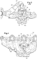
- the figure 1 shows a metallic air intake manifold 10 for supplying air to the cylinders of an internal combustion engine.
- the intake manifold 10 has openings for connection to the cylinders.
- This intake manifold 10 is connected to a pipe 12 for recycling the exhaust gases emitted by the engine.
- This pipe 12 is also metallic.
- the intake manifold 10 thus has an external opening 14 (visible figures 2 and 3 ) for connecting the exhaust gas recirculation pipe 12. As seen on the figure 3 , this external opening 14 communicates with a passage 16 passing through a wall 18 of the intake manifold 10.
- the passage 16 is shaped to diffuse a gas coming from the external opening 14 towards the interior of the intake manifold 10.
- This passage 16 has in particular a portion 16a the section of which decreases continuously from the external opening 14 up to a restricted section 20.
- the portion 16a does not have parts of constant section between the external opening 14 and the restricted section 20.
- This restricted section 20 is shaped to direct a gas circulating in the passage 16 towards the cylinders of the engine to which the intake manifold 10 is connected.
- the intake manifold 10 is connected to four cylinders (not shown).
- the portion 16a makes it possible to accelerate the gases entering the passage 16, thus promoting their diffusion inside the intake manifold 10.
- the shape of the restricted section 20 will allow the flow to be directed. of gas accelerated to the engine cylinders.
- the air intake manifold 10 has a passage 16, a portion 16b of which has a flared shape between the restricted section 20 and an internal end 17 of the passage 16, in other words between the restricted section 20 and the interior of the manifold d 'admission.
- This portion 16b of flared shape makes it possible to promote the direction of the flow of accelerated gas following its passage through the first portion 16a in the entire volume of the intake manifold 10 and in particular towards the ends of the intake manifold 10 which are connected to cylinders of the engine.
- This portion 16b of flared shape may in particular have a shoulder 22 for directing the gas flow in different directions inside the intake manifold 10.
- the flared section portion 16b is not directly adjacent to the restricted section 20, but is adjacent to a portion 16c of constant section itself adjacent to the restricted section 20.
- the section portion 16a the section of which decreases continuously from the example of figures 1 to 3 has a substantially frustoconical shape.
- the shape of the restricted section 20, visible on the figure 2 is roughly oval. It is thus elongated in shape, its ends being directed towards the most distant cylinders to which the intake manifold is connected. In other words, the length of the restricted section 20 of elongated shape extends substantially parallel to a line connecting the connection openings of the intake manifold to the cylinders of the engine.
- the restricted section 20 extends substantially in a plane parallel to the plane containing the external opening 14.
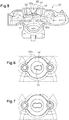
- the portion 16'a whose section continuously decreases is substantially frustoconical and asymmetrical ( figure 5 ).
- the shape of the restricted section 20 ' differs from the shape of the restricted section of the previous embodiment in order to distribute the gas entering through the EGR line (not shown) to the 3 cylinders to which the intake manifold 10' is connected.
- the restricted section 20 ' is substantially pear-shaped (see figures 4 and 6 ) and extends in two planes inclined with respect to each other, as visible on the figure 4 .
- the restricted section 20 thus has two rounded indentations, one of which has a greater radius on the side of the intake manifold connected to two cylinders of the engine and the other of smaller radius on the side of the intake manifold connected to the third cylinder of the engine. .
- the restricted section 20 ′ may have a variable shape depending on the shape of the intake manifold and on the position of the engine cylinders connected to this intake manifold. It may thus have an oval, elliptical, crescent, pear-shaped, bone-like shape ( figure 7 ), ...
- the exhaust gas recirculation pipe 12 is fixed in the usual way by a flange 24 and two screws 26 passing through the flange 24 and screwed into the bores provided for this purpose of the intake manifold 10.
- a metal seal is arranged between flange 24 and intake manifold 10.
- the invention has the advantage of integrating in one and the same part the intake manifold and a diffuser for the recycled exhaust gases. This makes it possible to simplify the mounting of the exhaust gas recirculation pipe on the intake manifold, but also to limit the risks of loss of the diffuser by disconnection. In addition, the diffusion of the gases is improved by the particular shape of the walls of the passage forming the diffuser.
Landscapes
- Engineering & Computer Science (AREA)
- Chemical & Material Sciences (AREA)
- Combustion & Propulsion (AREA)
- Mechanical Engineering (AREA)
- General Engineering & Computer Science (AREA)
- Exhaust-Gas Circulating Devices (AREA)
Description
L'invention concerne un collecteur d'admission pour un moteur à combustion interne de véhicule automobile.The invention relates to an intake manifold for an internal combustion engine of a motor vehicle.
Un collecteur d'admission, également appelé répartiteur, a pour fonction de fournir, à chaque cylindre du moteur, la quantité d'air nécessaire à une combustion complète du carburant.An intake manifold, also called a distributor, has the function of supplying, to each cylinder of the engine, the quantity of air necessary for complete combustion of the fuel.
Certains moteurs sont équipés d'un recyclage des gaz d'échappement (EGR), lequel permet d'abaisser le taux d'oxygène dans le mélange air carburant. En général, ces gaz d'échappement recyclés sont amenés au collecteur d'admission par une conduite métallique débouchant à l'intérieur du collecteur d'admission. Dans ce dernier, la diffusion des gaz d'échappement recyclés avec l'air frais venant du filtre d'air est obtenue par un diffuseur de gaz, généralement disposé à la jonction entre la conduite d'amenée des gaz d'échappement recyclés et le collecteur d'admission. Dans certains moteurs, le collecteur d'admission est en matériau polymère et le diffuseur est une pièce rapportée métallique, par exemple en acier inoxydable. Ce diffuseur métallique comprend une partie tronconique dont l'extrémité de plus grand diamètre est raccordée à la conduite EGR et l'extrémité de plus petit diamètre est raccordée à une partie cylindrique qui fait saillie à l'intérieur du collecteur d'admission. L'extrémité libre de la partie cylindrique, située sensiblement au centre du collecteur d'admission, présente des ouvertures latérales pour la diffusion des gaz. Cet agencement permet d'éviter que les gaz d'échappement ne soient en contact direct avec le matériau polymère constituant le collecteur d'admission, protégeant ainsi les parois de celui-ci de la chaleur des EGR. Toutefois, la diffusion n'est pas toujours optimale. En outre, ce diffuseur est généralement soudé à l'embouchure de la conduite d'amenée des gaz d'échappement. Il existe ainsi un risque de désolidarisation du diffuseur et de chute de ce dernier à l'intérieur du collecteur d'admission, susceptible de perturber le fonctionnement du moteur et d'endommager celui-ci. Enfin, un tel diffuseur en matériau métallique est relativement coûteux à réaliser.Some engines are equipped with exhaust gas recirculation (EGR), which lowers the level of oxygen in the air fuel mixture. In general, these recycled exhaust gases are brought to the intake manifold by a metal pipe opening inside the intake manifold. In the latter, the diffusion of the recycled exhaust gases with the fresh air coming from the air filter is obtained by a gas diffuser, generally arranged at the junction between the supply pipe of the recycled exhaust gases and the intake manifold. In some engines, the intake manifold is made of a polymeric material and the diffuser is a metallic insert, for example stainless steel. This metallic diffuser comprises a frustoconical part, the larger diameter end of which is connected to the EGR pipe and the smaller diameter end is connected to a cylindrical part which protrudes inside the intake manifold. The free end of the cylindrical part, located substantially in the center of the intake manifold, has side openings for the diffusion of gases. This arrangement makes it possible to prevent the exhaust gases from coming into direct contact with the polymer material constituting the intake manifold, thus protecting the walls thereof from the heat of the EGRs. However, dissemination is not always optimal. In addition, this diffuser is generally welded to the mouth of the exhaust gas supply pipe. There is thus a risk of the diffuser becoming detached and of the latter falling inside the intake manifold, liable to disrupt the operation of the engine and damage it. Finally, such a diffuser made of metallic material is relatively expensive to produce.
La publication
Il existe donc un besoin pour améliorer la diffusion des gaz EGR à l'intérieur d'un collecteur d'admission, notamment en la rendant plus sûre et ce, à moindre coût.There is therefore a need to improve the diffusion of EGR gases inside an intake manifold, in particular by making it safer and at lower cost.
A cet effet l'invention concerne un collecteur d'admission d'air métallique pour l'alimentation en air des cylindres d'un moteur à combustion interne selon la revendication 1. Ainsi, le passage forme un diffuseur intégré au collecteur d'admission d'air. Il n'y a ainsi plus de risque de désolidarisation du diffuseur du collecteur d'admission, réduisant ainsi le risque de panne du moteur. Autrement dit, le collecteur d'admission d'air selon l'invention présente un diffuseur réalisé d'un seul tenant avec le collecteur. Ce diffuseur intégré à la paroi du collecteur d'admission ne comprend donc pas de partie saillante vers l'intérieur du collecteur d'admission depuis la paroi de ce dernier, contrairement aux diffuseurs rapportés de l'art antérieur. L'agencement selon l'invention permet cependant d'obtenir une bonne diffusion des EGR à l'intérieur du collecteur d'admission en choisissant une forme appropriée de la section restreinte et de forme allongée, la portion dont la section diminue permettant l'accélération des gaz. Le collecteur d'admission selon l'invention peut notamment être réalisé de manière simple par moulage, par exemple en aluminium.To this end, the invention relates to a metallic air intake manifold for supplying air to the cylinders of an internal combustion engine according to
Avantageusement et de manière non limitative, le passage peut présenter une portion de forme évasée entre la section restreinte et une extrémité interne dudit passage. Une telle forme évasée permet d'améliorer la redirection des gaz traversant ledit passage vers l'intérieur du collecteur d'admission, en particulier vers les cylindres du moteur. Cette forme évasée peut s'étendre depuis la section restreinte ou depuis une partie de section constante adjacente à la section restreinte.Advantageously and in a nonlimiting manner, the passage may have a portion of flared shape between the restricted section and an internal end of said passage. Such a flared shape makes it possible to improve the redirection of the gases passing through said passage towards the interior of the intake manifold, in particular towards the cylinders of the engine. This shape The flare may extend from the restricted section or from a portion of constant section adjacent to the restricted section.
Notamment, la portion de forme évasée peut présenter au moins un épaulement, ce qui peut également favoriser l'orientation du gaz circulant dans ledit passage vers les cylindres du moteur.In particular, the portion of flared shape may have at least one shoulder, which may also promote the orientation of the gas flowing in said passage towards the cylinders of the engine.
De manière générale, la forme de la portion dont la section diminue de manière continue peut être déterminée afin de permettre une accélération des gaz entrants, notamment suffisante pour permettre la diffusion de ces gaz. Cette détermination fait partie des connaissances de l'homme du métier.In general, the shape of the portion of which the section continuously decreases can be determined in order to allow acceleration of the incoming gases, in particular sufficient to allow the diffusion of these gases. This determination is part of the knowledge of those skilled in the art.
Selon l'invention et pour une réalisation plus simple, la portion dont la section diminue de manière continue peut présenter une forme tronconique ou sensiblement tronconique, symétrique ou asymétrique. Une accélération correcte des gaz entrant peut par exemple être obtenue avec un angle au sommet de la forme tronconique ou sensiblement tronconique de 15° à 35°, de préférence de 20° à 30°. Cet angle pourra cependant être adapté en fonction de la forme du collecteur d'admission considéré.According to the invention and for a simpler embodiment, the portion whose section continuously decreases may have a frustoconical or substantially frustoconical, symmetrical or asymmetrical shape. Correct acceleration of the incoming gases can for example be obtained with an angle at the top of the frustoconical or substantially frustoconical shape of 15 ° to 35 °, preferably 20 ° to 30 °. This angle may however be adapted depending on the shape of the intake manifold considered.
Avantageusement et de manière non limitative, la section restreinte peut s'étendre au moins en partie dans un plan incliné par rapport à un plan contenant l'ouverture externe du passage. Ceci peut permettre de diriger de manière plus efficace les gaz circulant à l'intérieur du passage vers les cylindres auxquels est raccordé le collecteur d'admission. Ainsi, par exemple, une partie de la section restreinte qui s'étend dans un plan incliné peut permettre de diriger les gaz vers un cylindre disposé à une extrémité du collecteur d'admission, du côté où s'étend ce plan incliné.Advantageously and in a nonlimiting manner, the restricted section can extend at least in part in a plane inclined with respect to a plane containing the external opening of the passage. This can allow the gases flowing within the passage to be directed more efficiently to the cylinders to which the intake manifold is connected. Thus, for example, a part of the restricted section which extends in an inclined plane can make it possible to direct the gases towards a cylinder arranged at one end of the intake manifold, on the side where this inclined plane extends.
La section restreinte peut en outre s'étendre en partie dans un premier plan par exemple parallèle au plan contenant l'ouverture externe, et en partie dans au moins un autre plan incliné par rapport à ce dernier, en fonction de l'orientation que l'on souhaite donner aux gaz entrants par le passage.The restricted section may also extend partly in a first plane, for example parallel to the plane containing the external opening, and partly in at least one other plane inclined relative to the latter, depending on the orientation that the 'we want to give the incoming gases through the passage.
Afin d'améliorer la distribution du gaz circulant à l'intérieur du passage vers les cylindres du moteur, la section restreinte peut présenter une forme oblongue à bords arrondis, par exemple choisie parmi un ovale, une ellipse, une forme semblable à une poire, une forme semblable à un croissant, une forme présentant deux bords parallèles reliés par des extrémités arrondies, une forme présentant deux bords parallèles reliés par des portions de cercle de diamètre supérieur à la distance séparant les bords parallèles, une combinaison d'une ou plusieurs de ces formes ou toute autre forme oblongue. Ces formes oblongues peuvent s'étendre dans un ou plusieurs plans, tel que déjà mentionné.In order to improve the distribution of the gas flowing inside the passage to the cylinders of the engine, the restricted section may have an oblong shape with rounded edges, for example chosen from an oval, an ellipse, a shape similar to a pear, a crescent-like shape, a shape having two parallel edges connected by rounded ends, a shape having two parallel edges connected by portions of a circle with a diameter greater than the distance between the parallel edges, a combination of one or more of these shapes or any other oblong shape. These oblong shapes can extend in one or more planes, as already mentioned.
La section restreinte peut en outre présenter des formes échancrées arrondies en direction d'au moins un cylindre du moteur auquel ledit collecteur d'admission est raccordé. Notamment, la section restreinte peut présenter une forme échancrée en direction de chaque cylindre du moteur, ce qui peut permettre de favoriser la distribution du gaz circulant dans le passage vers ce cylindre.The restricted section may also have scalloped shapes rounded towards at least one cylinder of the engine to which said intake manifold is connected. In particular, the restricted section may have a notched shape in the direction of each cylinder of the engine, which may make it possible to promote the distribution of the gas flowing in the passage to this cylinder.
L'invention concerne également un moteur à combustion interne comprenant un collecteur d'admission d'air selon l'invention et une conduite de recyclage des gaz d'échappement émis par le moteur, ladite conduite étant raccordée à ladite ouverture externe dudit collecteur d'admission d'air.The invention also relates to an internal combustion engine comprising an air intake manifold according to the invention and a pipe for recycling the exhaust gases emitted by the engine, said pipe being connected to said external opening of said manifold. air intake.
L'invention concerne enfin un véhicule automobile comprenant un moteur à combustion interne selon l'invention.The invention finally relates to a motor vehicle comprising an internal combustion engine according to the invention.
L'invention est maintenant décrite en référence aux dessins annexés, non limitatifs, dans lesquels :
- la
figure 1 est une vue de dessus d'un collecteur d'admission d'air selon un mode de réalisation de l'invention, raccordé à une conduite de recyclage des gaz d'échappement ; - la
figure 2 est une vue similaire à celle de lafigure 1 , sans la conduite de recyclage des gaz d'échappement ; - la
figure 3 est une vue en coupe selon la ligne AA de lafigure 1 ; - la
figure 4 représente une vue en perspective du dessus d'un collecteur d'admission selon un autre mode de réalisation ; - la
figure 5 représente une vue en coupe selon la ligne AA de lafigure 4 ; - la
figure 6 représente une vue agrandie de dessus de l'ouverture externe du passage de lafigure 4 ; - la
figure 7 est une vue similaire à lafigure 6 dans laquelle la section restreinte présente une autre forme.
- the
figure 1 is a top view of an air intake manifold according to one embodiment of the invention, connected to an exhaust gas recirculation pipe; - the
figure 2 is a view similar to that of thefigure 1 , without the exhaust gas recirculation line; - the
figure 3 is a sectional view along line AA of thefigure 1 ; - the
figure 4 shows a perspective view from above of an intake manifold according to another embodiment; - the
figure 5 shows a sectional view along line AA of thefigure 4 ; - the
figure 6 shows an enlarged view from above of the external opening of the passage of thefigure 4 ; - the
figure 7 is a view similar tofigure 6 in which the restricted section has another shape.
Par sensiblement parallèle, perpendiculaire, on entend une direction s'écartant d'au plus ±20°, voire d'au plus 10° ou d'au plus 5° d'une direction parallèle, perpendiculaire.By substantially parallel, perpendicular is meant a direction deviating by at most ± 20 °, or even by at most 10 ° or by at most 5 ° from a parallel, perpendicular direction.
La
Le collecteur d'admission 10 présente ainsi une ouverture externe 14 (visible
Selon l'invention, le passage 16 est conformé pour diffuser un gaz provenant de l'ouverture externe 14 vers l'intérieur du collecteur d'admission 10. Ce passage 16 présente notamment une portion 16a dont la section diminue de manière continue depuis l'ouverture externe 14 jusqu'à une section restreinte 20. Autrement dit, la portion 16a ne présente pas de parties de section constante entre l'ouverture externe 14 et la section restreinte 20. Cette section restreinte 20 est conformée pour diriger un gaz circulant dans le passage 16 en direction des cylindres du moteur auquel le collecteur d'admission 10 est raccordé. Dans l'exemple représenté sur les
La portion 16a dont la section diminue de manière continue permet d'accélérer les gaz entrant dans le passage 16, favorisant ainsi leur diffusion à l'intérieur du collecteur d'admission 10. La forme de la section restreinte 20 va permettre de diriger le flux de gaz accélérés vers les cylindres du moteur.The
On notera que dans l'exemple représenté
La portion 16a de section dont la section diminue de manière continue de l'exemple des
Ici, la section restreinte 20 s'étend sensiblement dans un plan parallèle au plan contenant l'ouverture externe 14.Here, the restricted
Le mode de réalisation représenté sur les
Dans le mode de réalisation représenté sur les
On comprend ainsi que la section restreinte 20' peut présenter une forme variable en fonction de la forme du collecteur d'admission et de la position des cylindres du moteur raccordés à ce collecteur d'admission. Elle peut ainsi présenter une forme ovale, elliptique, en croissant, en forme de poire, en forme semblable à un os (
On notera que de manière générale, quelque soit la forme du passage, ce dernier est réalisé dans une partie de la paroi du collecteur d'admission qui présente une épaisseur plus importante pour permettre la fixation de la conduite d'échappement de recyclage des gaz.It will be noted that in general, whatever the shape of the passage, the latter is produced in a part of the wall of the intake manifold which has a greater thickness to allow the attachment of the exhaust pipe for recycling the gases.
Tel que représenté sur les
L'invention présente l'avantage d'intégrer en une seule et même pièce le collecteur d'admission et un diffuseur des gaz d'échappement recyclés. Ceci permet de simplifier le montage de la conduite de recyclage des gaz d'échappement sur le collecteur d'admission, mais également de limiter les risques de perte du diffuseur par désolidarisation. En outre, la diffusion des gaz se trouve améliorée de par la forme particulière des parois du passage formant le diffuseur.The invention has the advantage of integrating in one and the same part the intake manifold and a diffuser for the recycled exhaust gases. This makes it possible to simplify the mounting of the exhaust gas recirculation pipe on the intake manifold, but also to limit the risks of loss of the diffuser by disconnection. In addition, the diffusion of the gases is improved by the particular shape of the walls of the passage forming the diffuser.
Claims (8)
- Metallic air intake manifold (10, 10') for supplying the cylinders of an internal combustion engine with air, said intake manifold (10, 10') having an external opening (14, 14') intended to be connected to a pipe (12) for recirculating the exhaust gases emitted by the engine, said external opening (14, 14') communicating with a passage (16, 16') passing through a wall (18, 18') of said intake manifold (10, 10') and opening into the latter, characterized in that said passage (16, 16') is shaped so as to diffuse a gas coming from the external opening (14, 14') into said intake manifold (10, 10'), said passage (16, 16') passing through the wall (18, 18') of the manifold having a portion (16a, 16'a) of symmetric or asymmetric and frustoconical or substantially frustoconical shape, the section of which decreases continuously from the external opening (14, 14') to a restricted section of elongate shape (20, 20'), its ends being directed towards the furthest cylinders to which the intake manifold is connected, in order to accelerate and direct a gas circulating in said passage (16, 16') in the direction of the engine cylinders to which said intake manifold is connected, the length of said restricted section of elongate shape extending substantially parallel to a line joining openings for connecting the intake manifold to the engine cylinders.
- Air intake manifold (10, 10') according to Claim 1, characterized in that the passage (16, 16') has a portion (16b, 16'b) of flared shape between the restricted section (20, 20') and an internal end (17, 17') of said passage.
- Air intake manifold (10, 10') according to Claim 2, characterized in that the portion (16b, 16'b) of flared shape has at least one shoulder (22, 22').
- Air intake manifold (10, 10') according to any one of Claims 1 to 3, characterized in that the restricted section (20, 20') extends at least partially in a plane inclined relative to a plane containing the external opening (14, 14') of the passage.
- Air intake manifold (10, 10') according to any one of Claims 1 to 4, characterized in that the restricted section (20, 20') has an oblong shape with rounded edges, for example chosen from an oval, an ellipse, a pear-like shape, a crescent-like shape, a shape with two parallel edges connected by rounded ends, a shape with two parallel edges connected by portions of a circle with a diameter greater than the distance separating the parallel edges, a combination of one or more of these shapes or any other oblong shape.
- Air intake manifold (10, 10') according to any one of Claims 1 to 5, characterized in that the restricted section (20, 20') has shapes that are notched and rounded in the direction of at least one engine cylinder to which said intake manifold is connected.
- Internal combustion engine comprising an air intake manifold (10, 10') according to any one of Claims 1 to 6 and a pipe (12) for recirculating the exhaust gases emitted by the engine, said pipe being connected to said external opening (14, 14') of said air intake manifold.
- Motor vehicle comprising an internal combustion engine according to Claim 7.
Applications Claiming Priority (2)
| Application Number | Priority Date | Filing Date | Title |
|---|---|---|---|
| FR1452710A FR3019231B1 (en) | 2014-03-28 | 2014-03-28 | INTAKE MANIFOLD FOR AN INTERNAL COMBUSTION ENGINE OF A MOTOR VEHICLE |
| PCT/FR2015/050588 WO2015145015A1 (en) | 2014-03-28 | 2015-03-10 | Intake manifold for an internal combustion engine of a motor vehicle |
Publications (2)
| Publication Number | Publication Date |
|---|---|
| EP3134635A1 EP3134635A1 (en) | 2017-03-01 |
| EP3134635B1 true EP3134635B1 (en) | 2020-08-12 |
Family
ID=51261001
Family Applications (1)
| Application Number | Title | Priority Date | Filing Date |
|---|---|---|---|
| EP15714597.0A Active EP3134635B1 (en) | 2014-03-28 | 2015-03-10 | Intake manifold for an internal combustion engine of an automotive vehicle |
Country Status (3)
| Country | Link |
|---|---|
| EP (1) | EP3134635B1 (en) |
| FR (1) | FR3019231B1 (en) |
| WO (1) | WO2015145015A1 (en) |
Family Cites Families (7)
| Publication number | Priority date | Publication date | Assignee | Title |
|---|---|---|---|---|
| DE102004013309B4 (en) * | 2004-03-17 | 2015-09-24 | Mahle Filtersysteme Gmbh | Intake system for an internal combustion engine |
| CN101646849B (en) * | 2007-03-23 | 2011-10-05 | 贝洱两合公司 | Charging fluid suction module and internal combustion engine |
| JP2009156043A (en) * | 2007-12-25 | 2009-07-16 | Nissan Diesel Motor Co Ltd | Intake manifold |
| FR2945963A1 (en) * | 2009-05-27 | 2010-12-03 | Mark Iv Systemes Moteurs Sa | DEVICE FOR INJECTING AND DIFFUSING GASEOUS FLUID AND ADMISSION DISTRIBUTION INTEGRATING SUCH A DEVICE |
| KR200459733Y1 (en) * | 2009-07-17 | 2012-04-16 | 말레동현필터시스템 주식회사 | Device for Connecting EGR pipe with Intake Manifold |
| JP5813017B2 (en) * | 2010-02-17 | 2015-11-17 | ボーグワーナー インコーポレーテッド | Turbocharger |
| US8689553B2 (en) * | 2011-01-18 | 2014-04-08 | GM Global Technology Operations LLC | Exhaust gas recirculation system for an internal combustion engine |
-
2014
- 2014-03-28 FR FR1452710A patent/FR3019231B1/en not_active Expired - Fee Related
-
2015
- 2015-03-10 EP EP15714597.0A patent/EP3134635B1/en active Active
- 2015-03-10 WO PCT/FR2015/050588 patent/WO2015145015A1/en not_active Ceased
Non-Patent Citations (1)
| Title |
|---|
| None * |
Also Published As
| Publication number | Publication date |
|---|---|
| WO2015145015A1 (en) | 2015-10-01 |
| EP3134635A1 (en) | 2017-03-01 |
| FR3019231A1 (en) | 2015-10-02 |
| FR3019231B1 (en) | 2018-06-08 |
Similar Documents
| Publication | Publication Date | Title |
|---|---|---|
| CA2453007C (en) | Highly compact internal flame gas burner | |
| CA2577523C (en) | Turbine engine annular combustion chamber with alternating attachments | |
| CA2639980C (en) | Turbomachine combustion chamber | |
| FR3050228A1 (en) | AIR JET COOLING DEVICE OF A TURBINE HOUSING | |
| CA2615029C (en) | Deflector for bottom of combustion chamber, combustion chamber equipped with said deflector and turbojet engine containing them | |
| FR3013805A1 (en) | COMBUSTION ASSEMBLY WITH ACCESS FACILITATES PREVAPORIZATION RODS. | |
| EP1930659A1 (en) | Jet engine combustion chamber | |
| CA2879517C (en) | Helicopter engine air intake with improved bypass flow | |
| FR2506837A1 (en) | EXHAUST GAS CONDUIT TO BE MOUNTED BETWEEN AN INTERNAL COMBUSTION ENGINE AND AN EXHAUST GAS TURBO-COMPRESSOR | |
| EP3134635B1 (en) | Intake manifold for an internal combustion engine of an automotive vehicle | |
| FR2925586A3 (en) | EXHAUST LINE OF A COMBUSTION ENGINE COMPRISING AN INTERMEDIATE CONDUIT | |
| WO2018036966A1 (en) | Fuel injector nozzle body | |
| WO2011039470A1 (en) | Gasket device for diffusing recirculated exhaust gases | |
| FR2663986A1 (en) | Exhaust manifold for an internal-combustion engine, and internal-combustion engine including such a manifold | |
| WO2020002858A1 (en) | Guiding device in a combustion chamber | |
| FR2739897A1 (en) | ANNULAR CARBIDE GAS RECYCLING DIFFUSER, FOR INTERNAL COMBUSTION ENGINE | |
| EP4717903A1 (en) | Exhaust nozzle of an engine for a space launcher equipped with a cooling system | |
| FR2925609A1 (en) | Intake collector for internal combustion engine of vehicle, has injection nozzle opening into intake duct in mounting position, where nozzle tangentially extends to inner wall of intake duct in mounting position | |
| FR3158983A1 (en) | Hydrogen and air injection system | |
| FR2935740A3 (en) | FUEL VAPOR INJECTION NOZZLE EQUIPPED WITH TWO INJECTION OPENINGS | |
| WO2019145212A1 (en) | Optimised air intake circuit for a power train of a vehicle | |
| FR2893674A1 (en) | INTERNAL COMBUSTION ENGINE AIR INTAKE DISTRIBUTION | |
| FR2954412A1 (en) | INTERNAL COMBUSTION ENGINE INCORPORATING AN EXHAUST GAS RECIRCULATION DEVICE | |
| FR2936299A1 (en) | PULSATORY BOILER WITH FLAP VALVE | |
| FR2898644A1 (en) | AIR DISTRIBUTOR OF AN INTERNAL COMBUSTION ENGINE |
Legal Events
| Date | Code | Title | Description |
|---|---|---|---|
| STAA | Information on the status of an ep patent application or granted ep patent |
Free format text: STATUS: THE INTERNATIONAL PUBLICATION HAS BEEN MADE |
|
| PUAI | Public reference made under article 153(3) epc to a published international application that has entered the european phase |
Free format text: ORIGINAL CODE: 0009012 |
|
| STAA | Information on the status of an ep patent application or granted ep patent |
Free format text: STATUS: REQUEST FOR EXAMINATION WAS MADE |
|
| 17P | Request for examination filed |
Effective date: 20160902 |
|
| AK | Designated contracting states |
Kind code of ref document: A1 Designated state(s): AL AT BE BG CH CY CZ DE DK EE ES FI FR GB GR HR HU IE IS IT LI LT LU LV MC MK MT NL NO PL PT RO RS SE SI SK SM TR |
|
| AX | Request for extension of the european patent |
Extension state: BA ME |
|
| DAV | Request for validation of the european patent (deleted) | ||
| DAX | Request for extension of the european patent (deleted) | ||
| STAA | Information on the status of an ep patent application or granted ep patent |
Free format text: STATUS: EXAMINATION IS IN PROGRESS |
|
| 17Q | First examination report despatched |
Effective date: 20171018 |
|
| REG | Reference to a national code |
Ref country code: DE Ref legal event code: R079 Ref document number: 602015057310 Country of ref document: DE Free format text: PREVIOUS MAIN CLASS: F02M0026000000 Ipc: F02M0035104000 |
|
| GRAP | Despatch of communication of intention to grant a patent |
Free format text: ORIGINAL CODE: EPIDOSNIGR1 |
|
| STAA | Information on the status of an ep patent application or granted ep patent |
Free format text: STATUS: GRANT OF PATENT IS INTENDED |
|
| RIC1 | Information provided on ipc code assigned before grant |
Ipc: F02M 35/104 20060101AFI20200203BHEP Ipc: F02M 35/10 20060101ALI20200203BHEP Ipc: F02M 26/19 20160101ALI20200203BHEP |
|
| INTG | Intention to grant announced |
Effective date: 20200310 |
|
| GRAS | Grant fee paid |
Free format text: ORIGINAL CODE: EPIDOSNIGR3 |
|
| GRAA | (expected) grant |
Free format text: ORIGINAL CODE: 0009210 |
|
| STAA | Information on the status of an ep patent application or granted ep patent |
Free format text: STATUS: THE PATENT HAS BEEN GRANTED |
|
| AK | Designated contracting states |
Kind code of ref document: B1 Designated state(s): AL AT BE BG CH CY CZ DE DK EE ES FI FR GB GR HR HU IE IS IT LI LT LU LV MC MK MT NL NO PL PT RO RS SE SI SK SM TR |
|
| REG | Reference to a national code |
Ref country code: CH Ref legal event code: EP |
|
| REG | Reference to a national code |
Ref country code: IE Ref legal event code: FG4D Free format text: LANGUAGE OF EP DOCUMENT: FRENCH |
|
| REG | Reference to a national code |
Ref country code: DE Ref legal event code: R096 Ref document number: 602015057310 Country of ref document: DE |
|
| REG | Reference to a national code |
Ref country code: AT Ref legal event code: REF Ref document number: 1301778 Country of ref document: AT Kind code of ref document: T Effective date: 20200915 |
|
| REG | Reference to a national code |
Ref country code: LT Ref legal event code: MG4D |
|
| REG | Reference to a national code |
Ref country code: NL Ref legal event code: MP Effective date: 20200812 |
|
| PG25 | Lapsed in a contracting state [announced via postgrant information from national office to epo] |
Ref country code: BG Free format text: LAPSE BECAUSE OF FAILURE TO SUBMIT A TRANSLATION OF THE DESCRIPTION OR TO PAY THE FEE WITHIN THE PRESCRIBED TIME-LIMIT Effective date: 20201112 Ref country code: NO Free format text: LAPSE BECAUSE OF FAILURE TO SUBMIT A TRANSLATION OF THE DESCRIPTION OR TO PAY THE FEE WITHIN THE PRESCRIBED TIME-LIMIT Effective date: 20201112 Ref country code: SE Free format text: LAPSE BECAUSE OF FAILURE TO SUBMIT A TRANSLATION OF THE DESCRIPTION OR TO PAY THE FEE WITHIN THE PRESCRIBED TIME-LIMIT Effective date: 20200812 Ref country code: GR Free format text: LAPSE BECAUSE OF FAILURE TO SUBMIT A TRANSLATION OF THE DESCRIPTION OR TO PAY THE FEE WITHIN THE PRESCRIBED TIME-LIMIT Effective date: 20201113 Ref country code: LT Free format text: LAPSE BECAUSE OF FAILURE TO SUBMIT A TRANSLATION OF THE DESCRIPTION OR TO PAY THE FEE WITHIN THE PRESCRIBED TIME-LIMIT Effective date: 20200812 Ref country code: HR Free format text: LAPSE BECAUSE OF FAILURE TO SUBMIT A TRANSLATION OF THE DESCRIPTION OR TO PAY THE FEE WITHIN THE PRESCRIBED TIME-LIMIT Effective date: 20200812 Ref country code: FI Free format text: LAPSE BECAUSE OF FAILURE TO SUBMIT A TRANSLATION OF THE DESCRIPTION OR TO PAY THE FEE WITHIN THE PRESCRIBED TIME-LIMIT Effective date: 20200812 |
|
| REG | Reference to a national code |
Ref country code: AT Ref legal event code: MK05 Ref document number: 1301778 Country of ref document: AT Kind code of ref document: T Effective date: 20200812 |
|
| PG25 | Lapsed in a contracting state [announced via postgrant information from national office to epo] |
Ref country code: RS Free format text: LAPSE BECAUSE OF FAILURE TO SUBMIT A TRANSLATION OF THE DESCRIPTION OR TO PAY THE FEE WITHIN THE PRESCRIBED TIME-LIMIT Effective date: 20200812 Ref country code: NL Free format text: LAPSE BECAUSE OF FAILURE TO SUBMIT A TRANSLATION OF THE DESCRIPTION OR TO PAY THE FEE WITHIN THE PRESCRIBED TIME-LIMIT Effective date: 20200812 Ref country code: PL Free format text: LAPSE BECAUSE OF FAILURE TO SUBMIT A TRANSLATION OF THE DESCRIPTION OR TO PAY THE FEE WITHIN THE PRESCRIBED TIME-LIMIT Effective date: 20200812 Ref country code: LV Free format text: LAPSE BECAUSE OF FAILURE TO SUBMIT A TRANSLATION OF THE DESCRIPTION OR TO PAY THE FEE WITHIN THE PRESCRIBED TIME-LIMIT Effective date: 20200812 Ref country code: IS Free format text: LAPSE BECAUSE OF FAILURE TO SUBMIT A TRANSLATION OF THE DESCRIPTION OR TO PAY THE FEE WITHIN THE PRESCRIBED TIME-LIMIT Effective date: 20201212 |
|
| PG25 | Lapsed in a contracting state [announced via postgrant information from national office to epo] |
Ref country code: DK Free format text: LAPSE BECAUSE OF FAILURE TO SUBMIT A TRANSLATION OF THE DESCRIPTION OR TO PAY THE FEE WITHIN THE PRESCRIBED TIME-LIMIT Effective date: 20200812 Ref country code: CZ Free format text: LAPSE BECAUSE OF FAILURE TO SUBMIT A TRANSLATION OF THE DESCRIPTION OR TO PAY THE FEE WITHIN THE PRESCRIBED TIME-LIMIT Effective date: 20200812 Ref country code: EE Free format text: LAPSE BECAUSE OF FAILURE TO SUBMIT A TRANSLATION OF THE DESCRIPTION OR TO PAY THE FEE WITHIN THE PRESCRIBED TIME-LIMIT Effective date: 20200812 Ref country code: RO Free format text: LAPSE BECAUSE OF FAILURE TO SUBMIT A TRANSLATION OF THE DESCRIPTION OR TO PAY THE FEE WITHIN THE PRESCRIBED TIME-LIMIT Effective date: 20200812 Ref country code: SM Free format text: LAPSE BECAUSE OF FAILURE TO SUBMIT A TRANSLATION OF THE DESCRIPTION OR TO PAY THE FEE WITHIN THE PRESCRIBED TIME-LIMIT Effective date: 20200812 |
|
| REG | Reference to a national code |
Ref country code: DE Ref legal event code: R097 Ref document number: 602015057310 Country of ref document: DE |
|
| PG25 | Lapsed in a contracting state [announced via postgrant information from national office to epo] |
Ref country code: AL Free format text: LAPSE BECAUSE OF FAILURE TO SUBMIT A TRANSLATION OF THE DESCRIPTION OR TO PAY THE FEE WITHIN THE PRESCRIBED TIME-LIMIT Effective date: 20200812 Ref country code: AT Free format text: LAPSE BECAUSE OF FAILURE TO SUBMIT A TRANSLATION OF THE DESCRIPTION OR TO PAY THE FEE WITHIN THE PRESCRIBED TIME-LIMIT Effective date: 20200812 Ref country code: ES Free format text: LAPSE BECAUSE OF FAILURE TO SUBMIT A TRANSLATION OF THE DESCRIPTION OR TO PAY THE FEE WITHIN THE PRESCRIBED TIME-LIMIT Effective date: 20200812 |
|
| PLBE | No opposition filed within time limit |
Free format text: ORIGINAL CODE: 0009261 |
|
| STAA | Information on the status of an ep patent application or granted ep patent |
Free format text: STATUS: NO OPPOSITION FILED WITHIN TIME LIMIT |
|
| PG25 | Lapsed in a contracting state [announced via postgrant information from national office to epo] |
Ref country code: SK Free format text: LAPSE BECAUSE OF FAILURE TO SUBMIT A TRANSLATION OF THE DESCRIPTION OR TO PAY THE FEE WITHIN THE PRESCRIBED TIME-LIMIT Effective date: 20200812 |
|
| 26N | No opposition filed |
Effective date: 20210514 |
|
| PG25 | Lapsed in a contracting state [announced via postgrant information from national office to epo] |
Ref country code: IT Free format text: LAPSE BECAUSE OF FAILURE TO SUBMIT A TRANSLATION OF THE DESCRIPTION OR TO PAY THE FEE WITHIN THE PRESCRIBED TIME-LIMIT Effective date: 20200812 |
|
| PG25 | Lapsed in a contracting state [announced via postgrant information from national office to epo] |
Ref country code: SI Free format text: LAPSE BECAUSE OF FAILURE TO SUBMIT A TRANSLATION OF THE DESCRIPTION OR TO PAY THE FEE WITHIN THE PRESCRIBED TIME-LIMIT Effective date: 20200812 |
|
| PG25 | Lapsed in a contracting state [announced via postgrant information from national office to epo] |
Ref country code: MC Free format text: LAPSE BECAUSE OF FAILURE TO SUBMIT A TRANSLATION OF THE DESCRIPTION OR TO PAY THE FEE WITHIN THE PRESCRIBED TIME-LIMIT Effective date: 20200812 |
|
| REG | Reference to a national code |
Ref country code: CH Ref legal event code: PL |
|
| GBPC | Gb: european patent ceased through non-payment of renewal fee |
Effective date: 20210310 |
|
| REG | Reference to a national code |
Ref country code: BE Ref legal event code: MM Effective date: 20210331 |
|
| PG25 | Lapsed in a contracting state [announced via postgrant information from national office to epo] |
Ref country code: IE Free format text: LAPSE BECAUSE OF NON-PAYMENT OF DUE FEES Effective date: 20210310 Ref country code: GB Free format text: LAPSE BECAUSE OF NON-PAYMENT OF DUE FEES Effective date: 20210310 Ref country code: LI Free format text: LAPSE BECAUSE OF NON-PAYMENT OF DUE FEES Effective date: 20210331 Ref country code: LU Free format text: LAPSE BECAUSE OF NON-PAYMENT OF DUE FEES Effective date: 20210310 Ref country code: CH Free format text: LAPSE BECAUSE OF NON-PAYMENT OF DUE FEES Effective date: 20210331 |
|
| PG25 | Lapsed in a contracting state [announced via postgrant information from national office to epo] |
Ref country code: BE Free format text: LAPSE BECAUSE OF NON-PAYMENT OF DUE FEES Effective date: 20210331 |
|
| PG25 | Lapsed in a contracting state [announced via postgrant information from national office to epo] |
Ref country code: PT Free format text: LAPSE BECAUSE OF FAILURE TO SUBMIT A TRANSLATION OF THE DESCRIPTION OR TO PAY THE FEE WITHIN THE PRESCRIBED TIME-LIMIT Effective date: 20201214 |
|
| PG25 | Lapsed in a contracting state [announced via postgrant information from national office to epo] |
Ref country code: HU Free format text: LAPSE BECAUSE OF FAILURE TO SUBMIT A TRANSLATION OF THE DESCRIPTION OR TO PAY THE FEE WITHIN THE PRESCRIBED TIME-LIMIT; INVALID AB INITIO Effective date: 20150310 |
|
| PG25 | Lapsed in a contracting state [announced via postgrant information from national office to epo] |
Ref country code: CY Free format text: LAPSE BECAUSE OF FAILURE TO SUBMIT A TRANSLATION OF THE DESCRIPTION OR TO PAY THE FEE WITHIN THE PRESCRIBED TIME-LIMIT Effective date: 20200812 |
|
| P01 | Opt-out of the competence of the unified patent court (upc) registered |
Effective date: 20230608 |
|
| PG25 | Lapsed in a contracting state [announced via postgrant information from national office to epo] |
Ref country code: MK Free format text: LAPSE BECAUSE OF FAILURE TO SUBMIT A TRANSLATION OF THE DESCRIPTION OR TO PAY THE FEE WITHIN THE PRESCRIBED TIME-LIMIT Effective date: 20200812 |
|
| REG | Reference to a national code |
Ref country code: DE Ref legal event code: R081 Ref document number: 602015057310 Country of ref document: DE Owner name: NEW H POWERTRAIN HOLDING, S.L.U., ES Free format text: FORMER OWNER: RENAULT S.A.S., BOULOGNE BILLANCOURT, FR |
|
| PG25 | Lapsed in a contracting state [announced via postgrant information from national office to epo] |
Ref country code: TR Free format text: LAPSE BECAUSE OF FAILURE TO SUBMIT A TRANSLATION OF THE DESCRIPTION OR TO PAY THE FEE WITHIN THE PRESCRIBED TIME-LIMIT Effective date: 20200812 |
|
| PG25 | Lapsed in a contracting state [announced via postgrant information from national office to epo] |
Ref country code: MT Free format text: LAPSE BECAUSE OF FAILURE TO SUBMIT A TRANSLATION OF THE DESCRIPTION OR TO PAY THE FEE WITHIN THE PRESCRIBED TIME-LIMIT Effective date: 20200812 |
|
| PGFP | Annual fee paid to national office [announced via postgrant information from national office to epo] |
Ref country code: DE Payment date: 20260319 Year of fee payment: 12 |
|
| PGFP | Annual fee paid to national office [announced via postgrant information from national office to epo] |
Ref country code: FR Payment date: 20260320 Year of fee payment: 12 |