EP3480439A1 - Air intake circuit for spark ignition engine with plenum integrated in the cylinder head - Google Patents
Air intake circuit for spark ignition engine with plenum integrated in the cylinder head Download PDFInfo
- Publication number
- EP3480439A1 EP3480439A1 EP18204613.6A EP18204613A EP3480439A1 EP 3480439 A1 EP3480439 A1 EP 3480439A1 EP 18204613 A EP18204613 A EP 18204613A EP 3480439 A1 EP3480439 A1 EP 3480439A1
- Authority
- EP
- European Patent Office
- Prior art keywords
- air intake
- air
- cylinder head
- engine
- heat exchanger
- Prior art date
- Legal status (The legal status is an assumption and is not a legal conclusion. Google has not performed a legal analysis and makes no representation as to the accuracy of the status listed.)
- Withdrawn
Links
Images


Classifications
-
- F—MECHANICAL ENGINEERING; LIGHTING; HEATING; WEAPONS; BLASTING
- F02—COMBUSTION ENGINES; HOT-GAS OR COMBUSTION-PRODUCT ENGINE PLANTS
- F02B—INTERNAL-COMBUSTION PISTON ENGINES; COMBUSTION ENGINES IN GENERAL
- F02B29/00—Engines characterised by provision for charging or scavenging not provided for in groups F02B25/00, F02B27/00 or F02B33/00 - F02B39/00; Details thereof
- F02B29/04—Cooling of air intake supply
- F02B29/045—Constructional details of the heat exchangers, e.g. pipes, plates, ribs, insulation, materials, or manufacturing and assembly
- F02B29/0475—Constructional details of the heat exchangers, e.g. pipes, plates, ribs, insulation, materials, or manufacturing and assembly the intake air cooler being combined with another device, e.g. heater, valve, compressor, filter or EGR cooler, or being assembled on a special engine location
-
- F—MECHANICAL ENGINEERING; LIGHTING; HEATING; WEAPONS; BLASTING
- F02—COMBUSTION ENGINES; HOT-GAS OR COMBUSTION-PRODUCT ENGINE PLANTS
- F02M—SUPPLYING COMBUSTION ENGINES IN GENERAL WITH COMBUSTIBLE MIXTURES OR CONSTITUENTS THEREOF
- F02M35/00—Combustion-air cleaners, air intakes, intake silencers, or induction systems specially adapted for, or arranged on, internal-combustion engines
- F02M35/10—Air intakes; Induction systems
- F02M35/10006—Air intakes; Induction systems characterised by the position of elements of the air intake system in direction of the air intake flow, i.e. between ambient air inlet and supply to the combustion chamber
- F02M35/10026—Plenum chambers
- F02M35/10052—Plenum chambers special shapes or arrangements of plenum chambers; Constructional details
-
- F—MECHANICAL ENGINEERING; LIGHTING; HEATING; WEAPONS; BLASTING
- F02—COMBUSTION ENGINES; HOT-GAS OR COMBUSTION-PRODUCT ENGINE PLANTS
- F02M—SUPPLYING COMBUSTION ENGINES IN GENERAL WITH COMBUSTIBLE MIXTURES OR CONSTITUENTS THEREOF
- F02M35/00—Combustion-air cleaners, air intakes, intake silencers, or induction systems specially adapted for, or arranged on, internal-combustion engines
- F02M35/10—Air intakes; Induction systems
- F02M35/10242—Devices or means connected to or integrated into air intakes; Air intakes combined with other engine or vehicle parts
- F02M35/10268—Heating, cooling or thermal insulating means
-
- F—MECHANICAL ENGINEERING; LIGHTING; HEATING; WEAPONS; BLASTING
- F02—COMBUSTION ENGINES; HOT-GAS OR COMBUSTION-PRODUCT ENGINE PLANTS
- F02M—SUPPLYING COMBUSTION ENGINES IN GENERAL WITH COMBUSTIBLE MIXTURES OR CONSTITUENTS THEREOF
- F02M35/00—Combustion-air cleaners, air intakes, intake silencers, or induction systems specially adapted for, or arranged on, internal-combustion engines
- F02M35/10—Air intakes; Induction systems
- F02M35/10242—Devices or means connected to or integrated into air intakes; Air intakes combined with other engine or vehicle parts
- F02M35/10288—Air intakes combined with another engine part, e.g. cylinder head cover or being cast in one piece with the exhaust manifold, cylinder head or engine block
-
- F—MECHANICAL ENGINEERING; LIGHTING; HEATING; WEAPONS; BLASTING
- F02—COMBUSTION ENGINES; HOT-GAS OR COMBUSTION-PRODUCT ENGINE PLANTS
- F02B—INTERNAL-COMBUSTION PISTON ENGINES; COMBUSTION ENGINES IN GENERAL
- F02B29/00—Engines characterised by provision for charging or scavenging not provided for in groups F02B25/00, F02B27/00 or F02B33/00 - F02B39/00; Details thereof
- F02B29/04—Cooling of air intake supply
- F02B29/045—Constructional details of the heat exchangers, e.g. pipes, plates, ribs, insulation, materials, or manufacturing and assembly
- F02B29/0462—Liquid cooled heat exchangers
-
- Y—GENERAL TAGGING OF NEW TECHNOLOGICAL DEVELOPMENTS; GENERAL TAGGING OF CROSS-SECTIONAL TECHNOLOGIES SPANNING OVER SEVERAL SECTIONS OF THE IPC; TECHNICAL SUBJECTS COVERED BY FORMER USPC CROSS-REFERENCE ART COLLECTIONS [XRACs] AND DIGESTS
- Y02—TECHNOLOGIES OR APPLICATIONS FOR MITIGATION OR ADAPTATION AGAINST CLIMATE CHANGE
- Y02T—CLIMATE CHANGE MITIGATION TECHNOLOGIES RELATED TO TRANSPORTATION
- Y02T10/00—Road transport of goods or passengers
- Y02T10/10—Internal combustion engine [ICE] based vehicles
- Y02T10/12—Improving ICE efficiencies
Definitions
- the present invention relates to an air intake circuit for a spark ignition engine.
- the invention also relates to a spark ignition engine comprising such an air intake circuit.
- the invention relates to a motor vehicle comprising such an air intake circuit or such a spark ignition engine.
- This compression element may be a compressor of a turbocharger disposed between an air filter and an air intake manifold of the engine.
- the intake air has warmed which is detrimental to the efficiency of the engine.
- a heat exchanger is arranged in the air intake circuit, upstream of the engine, to cool the compressed air that enters the combustion chambers.
- the air intake manifold includes a throttle body, a volume of air buffer, also called plenum, and at least as many air intake lines as cylinders.
- the air distribution manifold, also called air intake manifold can be for example a casting or a plastic part fixed against the cylinder head.
- the intake manifold and intake manifolds are capable of generating aerodynamic turbulence in the combustion chamber to ideally mix gasoline with air for efficient combustion.
- the geometry and orientation of the air intake ducts relative to the combustion chamber play a vital role.
- the air intake manifold and heat exchanger are in addition to other equipment attached to the engine. All of this equipment makes the gasoline engine particularly complex to assemble and particularly bulky.
- the object of the invention is to provide an air intake circuit for a spark ignition engine, in particular for a gasoline engine, overcoming the above drawbacks and improving the air intake circuits for a spark ignition engine. known from the prior art.
- the invention makes it possible to produce an air intake circuit for a spark ignition engine and a spark ignition engine. including such an air intake circuit which are compact, easy to assemble, which can generate aerodynamic turbulence optimizing fuel combustion, and which limit the pressure drop of the air flow.
- the invention relates to an air intake circuit for a spark ignition engine, said air intake circuit being intended to be positioned between an air compression element and at least a chamber upper part. combustion engine in a cylinder head of the engine, said air intake circuit comprising the cylinder head, a heat exchanger, an air intake distributor, and at least one air intake duct, the distributor of air intake comprising a plenum formed at least partially by a recess in the cylinder head, the recess being covered by an air outlet of the heat exchanger.
- the recess can be closed airtight by the outlet mouth of the heat exchanger.
- the volume of the recess may be greater than or equal to a quarter of a cubic capacity of the engine, or even greater than or equal to one third of a cubic capacity of the engine.
- the plenum comprising at least one wall provided with a deflector adapted to deflect a flow of air to the at least one air intake duct.
- the cylinder head may be intended to be fixed to a cylinder block of an engine according to a plane of head gasket, the at least one upper part of the combustion chamber opening into the joint plane of the cylinder head, and the deflector may be formed by a downstream end wall of the plenum, substantially flat and inclined with respect to the yoke joint plane.
- the downstream end wall may comprise a lower portion from which opens the at least one air intake duct.
- the at least one air intake duct may extend along a first axis and the deflector may be formed by a downstream end wall of the plenum substantially flat and inclined relative to a plane perpendicular to the first axis so directing a flow of air to the at least one air intake duct.
- the at least one air intake pipe may extend along a first axis and the cylinder head may be intended to be fixed to a cylinder block of an engine according to a plan of a cylinder head gasket, the at least one an upper part of the combustion chamber opening into the yoke joint plane, the first axis forming a non-zero angle with the yoke joint plane, in particular to create a "tumble" type air turbulence in the at least one an upper part of the combustion chamber.
- the heat exchanger may comprise a water circuit.
- the heat exchanger may be directly fixed against the cylinder head, in particular the heat exchanger may comprise a flange fixed against the cylinder head.
- the invention also relates to a spark ignition engine comprising an air intake circuit as defined above.
- the volume of the heat exchanger can be substantially equal to a displacement of the engine.
- the invention also relates to a motor vehicle comprising an air intake circuit as defined above and / or a spark ignition engine as defined above.
- the invention also relates to a cylinder head for a gasoline engine comprising at least one air intake duct opening into at least one upper part of the combustion chamber, the cylinder head comprising at least a first part of a plenum. upstream of the at least one air intake pipe.
- upstream and downstream refer to the direction of propagation of the air within the engine, the air propagating from upstream to downstream.
- the lower and upper terms refer to the vertical axis.
- An engine is considered positioned so that its cylinders are parallel to the vertical axis but the invention could be transposed to a motor whose cylinders are not arranged vertically.
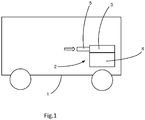
- the figure 1 illustrates a vehicle 1 automobile comprising a spark ignition engine 2 according to one embodiment of the invention.
- the engine may be for example a direct injection engine operating with gasoline or with a derivative or equivalent of gasoline such as ethanol, a biofuel, vehicle natural gas or liquefied petroleum gas.
- the engine includes a cylinder head 3 overcoming a cylinder block 4, also sometimes referred to as "engine block” or "casing".
- the engine 2 also includes an air intake circuit 5 through which air enters combustion chambers of the engine from the outside.
- the figures 2 and 3 illustrate more precisely the spark ignition engine 2.
- the engine comprises three cylinders 6 but alternatively it could include any number of cylinders, for example four or six cylinders.
- the air intake circuit 5 comprises the cylinder head 3, a heat exchanger 20, an air intake distributor, and at least one air intake duct 10.
- the air intake circuit 5 is positioned downstream of an air compression element, in particular a turbocharger compressor (not shown).
- the air intake distributor comprises a plenum 13 formed by a recess in the cylinder head 3.
- the cylinder block 4 comprises three combustion chambers 7 of generally cylindrical shape.
- the cylinder head 3 comprises three upper parts 8 of said combustion chambers, in each of which are arranged two air intake openings 9 communicating with the air intake ducts 10. Said air intake circuit 5 is therefore positioned upstream of the upper parts 8 of the combustion chamber. Air intake valves 11 set in motion by a camshaft 12 are able to close off the air intake openings 9.
- the upper portions 8 of said combustion chambers comprise a circular shape, in particular a conical shape, and constitute the upper end of the combustion chambers 7. Injectors, spark plugs or exhaust openings may also be arranged in the upper portions 8 of said combustion chambers 8.
- a combustion chamber axis Ac coincides with the axis of the cylinder 6.
- L The combustion chamber axis Ac is perpendicular to a yoke joint plane 31 delimiting cylinder head 3 of the cylinder block 4. In particular, when the vehicle rests on a horizontal ground, the combustion chamber axis may be vertical and the joint plane of the cylinder head 31 may be horizontal.
- the air intake ducts 10 are substantially constant section openings arranged entirely in the cylinder head. Downstream, they open into the upper parts 8 of said combustion chambers via the air intake openings 9. Upstream, the air intake ducts are connected within the cylinder head 3 to the plenum 13.
- the ducts air intake also called "primary pipes" to homogenize the speed of air before entering the combustion chambers.
- the length of the air intake ducts 10 may for example be between 50 mm and 100 mm.
- the section of the air intake ducts may for example be between 2.5 and 20 mm 2 .
- the plenum 13 is a buffer volume containing air ready to be sucked into one or more combustion chambers 7 when the air intake valves 11 open.
- the plenum 13 is formed by a recess in the cylinder head 3.
- the recess comprises side walls substantially parallel to the direction of flow of the air and a downstream end wall 15 into which the ducts
- a pressure wave passes through the air intake ducts 10 and These pressure waves can cause vibrations and / or affect the air filling of the cylinders.
- the shape and the volume of the air intake ducts 10 and the plenum 13 impact the pressure waves for a given engine speed as well as the aerodynamic movements in the combustion chamber and the pressure drop of the air flow.
- the shape and the volume of the air intake ducts 10 and the plenum 13 are thus adapted to each engine according to the desired use and, in particular, to reduce in an optimal way the pressure drops at the passage of the intake air.
- the primary lines are preferably straight with an evolution of the passage section, for example with a conical shape. They are in particular inclined along a straight ramp, that is to say with a uniform inclination towards the upper parts 8 of said combustion chambers.
- Each air intake pipe extends substantially along a first axis A1.
- the first axis A1 forms with the combustion chamber axis Ac an angle B1 greater than or equal to 45 °, or greater than or equal to 60 °.
- Each air intake duct opens into its upper combustion chamber 8 respectively substantially tangentially to the combustion chamber.
- the first axis A1 is not parallel to the joint plane of the yoke 31. In other words, the first axis A1 forms with the joint plane of the cylinder head 31 a non-zero angle.
- This orientation is particularly favorable for the formation of a "tumble" type aerodynamic disturbance inside the combustion chamber: when the air intake valves open, the air rushes into the cylinder by generating a vortex whose axis is perpendicular to the combustion chamber axis Ac.
- Such aerodynamic turbulence is illustrated in particular in the figure 9 .
- An arrow F1 indicates the orientation of the turbulence.
- This type of disturbance aerodynamic provides efficient combustion of fuel injected into the combustion chamber.
- the downstream end wall 15 of the cylinder head comprises inputs 14 of the various air intake ducts 10. These inputs 14 are materialized on the figures 2 and 3 by a dashed line.
- the plenum 13 also comprises an inlet 15 'disposed on one side 16 of the yoke, vis-à-vis the downstream end wall.
- the displacement of the engine is defined by the volume swept by the displacement of the pistons in their respective cylinders.
- the volume of the plenum is greater than or equal to the displacement of the engine divided by four, or even greater than or equal to the displacement of the engine divided by three.
- the downstream end wall 15 is substantially flat.
- the inlets 14 of the various intake ducts open into a lower part of the downstream end wall 15.
- the downstream end wall 15 is inclined with respect to a plane perpendicular to the first axis A1 and also inclined relative to the yoke joint plane 31.
- the downstream end wall 15 forms a deflector 18 adapted to direct the air flows to the inlet 14 of the various air intake ducts 10. The convergence of the Air flow from the plenum to the combustion chambers is thus favored and the pressure losses of the air flows are minimized.
- a second axis A2 can be defined as the axis perpendicular to the surface drawn by the plenum entry 13.
- An angle B2 formed between the first axis A1 and the second axis A2 is less than or equal to 30 °.
- the side 16 of the breech on which the plenum opens can be advantageously inclined relative to other sides of the cylinder head or with respect to the natural extension of the cylinder block 4 below the cylinder head.
- the breech may therefore comprise an outgrowth 17 in which the plenum or part of the plenum is arranged.
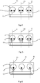
- the cylinder head comprises two air intake openings 9 in each upper part 8 of the combustion chamber.
- Each air intake duct 10 comprises a Y-shaped branch opening into its two respective air inlet openings. There are therefore three air intake ducts 10 each comprising one inlet and two outlets. Such a configuration is also observable on the figure 3 .
- the cylinder head also comprises two air intake openings 9 in each upper part 8 of the combustion chamber.
- Independent air inlet ducts 10 each open into an air inlet opening 9.
- each combustion chamber upper part comprises a single air intake opening 9.
- Independent air intake ducts 10 each open into an opening of air intake 9. There are therefore three air intake ducts 10 each comprising an inlet and an outlet.
- the air intake is symmetrically structured along a vertical plane P1 and median of each upper portion 8 of the combustion chamber.
- the flow of air entering the combustion chamber is balanced on both sides of the plane P1.
- No aerodynamic turbulence is established around the combustion chamber axis Ac. Aerodynamic turbulence is thus established only around an axis perpendicular to the axis of combustion chamber Ac.
- the turbulence is of the "tumble" type as illustrated on the figure 9 .
- the heat exchanger 20 is positioned upstream of the cylinder head (and therefore also upstream of the plenum integrated with the cylinder head).
- the heat exchanger 20 is in the form of a housing provided with a water circuit.
- the heat exchanger comprises an inlet mouth 27 of air and an outlet mouth 28 of air.
- the water circuit comprises an inlet 21 and an outlet 22. Because of its high heat capacity, the water is able to effectively cool the air passing through the heat exchanger.
- Such an exchanger is commonly referred to by its English abbreviation WCAC meaning "water charge air cooler” or “water charge air cooler”.
- the volume of the heat exchanger 20 is substantially equal to the displacement of the engine.
- the heat exchanger 20 comprises a fastening flange 23 fixed (for example screwed) directly against the side 16 of the cylinder head.
- the connection between the heat exchanger 20 and the cylinder head 3, in particular between the outlet port 28 and the cylinder head 3, is sealed.
- the heat exchanger thus opens directly into the plenum 13 without the air passing through a conduct.
- Upstream of the heat exchanger 20, the air is supplied by an air duct 24.
- a throttle valve 25 arranged in the air duct 24 regulates the flow of air into the engine.
- the outlet mouth 28 is oriented along a third axis A3 and the inlet mouth 27 is oriented along a fourth axis A4.
- An angle B3 formed between the first axis A1 and the third axis A3 is less than or equal to 30 °.
- An angle B4 formed between the first axis A1 and the fourth axis A4 is less than or equal to 30 °.
- the air inlet and the air outlet of the heat exchanger are parallel to each other and parallel to the inlet 15 'of the plenum.
- the second axis A2, the third axis A3 and the fourth axis A4 are therefore merged.
- the angles B2, B3 and B4 are identical.
- the outlet mouth 28 of the exchanger is fixed to the cylinder head in an airtight manner and the passage section of said outlet mouth 28 is directly connected to the plenum.
- the air intake distributor is formed by the recess in the cylinder head covered by the exchanger.
- the Figures 7 and 8 illustrate two variants of arrangement of the plenum.
- a first variant arrangement illustrated on the figure 7 the entire plenum is integrated into the breech.
- a second variant of arrangement illustrated on the figure 8 only a first part 13a of the plenum is integrated in the cylinder head.
- the air intake circuit 5 comprises an interface 26 interposed between the yoke 3 and the heat exchanger 20 delimits a second portion 13b of plenum.
- the first part 13a of plenum communicates with the second part 13b of plenum.
- the first part 13a of plenum and the second part 13b of plenum are complementary and together form the plenum.
- the interface 26 may be a separate element of the cylinder head and the heat exchanger, for example a tubular piece positioned between the cylinder head and the exchanger thermal.
- the heat exchanger 20 and the interface 26 may form a single assembly comprising the second portion 13b of the plenum.
- the heat exchanger 20 can integrate the interface 26: the air contained inside the heat exchanger, in particular near the outlet of the heat exchanger, can be the second part 13b of the plenum.
- the plenum is downstream of the heat exchanger, or downstream and partially in the heat exchanger. However, no part of the plenum is upstream of the heat exchanger.
- the interface and the heat exchanger do not include distribution ducts directed towards one or the other of the combustion chambers. The distribution of air in the combustion chambers is performed in the cylinder head at the junction between the air intake ducts 10 and the first plenum portion 13a.
- the heat exchanger is attached directly to the cylinder head or at least near the cylinder head. This set is therefore particularly compact.
- the cantilever related to the attachment of the heat exchanger on the cylinder head is also very low.
- the assembly formed by the cylinder head and the heat exchanger is also particularly rigid, which reduces the amplitude of the relative movements of these parts when they are subjected to vibrations.
- the plenum is advantageously made at least in part by a first volume arranged in the cylinder head.
- This first volume is delimited by the side walls of the cylinder head, the downstream end wall comprising the inlet ducts and a cylinder head provided for fixing the remainder of the intake circuit.
- This first volume is not intended to receive parts when the engine is assembled, but to form a first part of plenum.
- a second part of plenum complementary to the first part to form together the plenum, may be provided at one or more other elements of the air intake circuit 5 forming upstream of the first volume, a second volume. This second volume is in continuity with the first volume.
Landscapes
- Engineering & Computer Science (AREA)
- Chemical & Material Sciences (AREA)
- Combustion & Propulsion (AREA)
- Mechanical Engineering (AREA)
- General Engineering & Computer Science (AREA)
- Physics & Mathematics (AREA)
- Thermal Sciences (AREA)
- Geometry (AREA)
- Cylinder Crankcases Of Internal Combustion Engines (AREA)
Abstract
Circuit d'admission d'air (5) pour un moteur (2) à allumage commandé, ledit circuit d'admission d'air (5) étant destiné à être positionné entre un élément de compression d'air et au moins une partie supérieure (8) de chambre de combustion creusée dans une culasse (3) du moteur (2), ledit circuit d'admission d'air (5) comprenant la culasse (3), un échangeur thermique (20), un répartiteur d'admission d'air, et au moins une conduite d'admission d'air (10), caractérisé en ce que le répartiteur d'admission d'air comprend un plénum (13) formé au moins partiellement par un évidement dans la culasse (3), l'évidement étant recouvert par une bouche de sortie (28) d'air de l'échangeur thermique (20).An air intake circuit (5) for a spark ignition engine (2), said air intake circuit (5) being adapted to be positioned between an air compression member and at least one upper portion Combustion chamber (8) in a cylinder head (3) of the engine (2), said air intake circuit (5) comprising the cylinder head (3), a heat exchanger (20), an intake distributor of air, and at least one air intake duct (10), characterized in that the air intake manifold comprises a plenum (13) formed at least partly by a recess in the cylinder head (3) , the recess being covered by an air outlet (28) of the heat exchanger (20).
Description
La présente invention concerne un circuit d'admission d'air pour moteur à allumage commandé. L'invention concerne également un moteur à allumage commandé comprenant un tel un circuit d'admission d'air. Enfin, l'invention concerne un véhicule automobile comprenant un tel circuit d'admission d'air ou un tel moteur à allumage commandé.The present invention relates to an air intake circuit for a spark ignition engine. The invention also relates to a spark ignition engine comprising such an air intake circuit. Finally, the invention relates to a motor vehicle comprising such an air intake circuit or such a spark ignition engine.
Afin de respecter les normes internationales d'émissions des moteurs à allumage commandé, notamment des moteurs à essence, les constructeurs automobiles cherchent à optimiser la combustion du carburant, notamment de l'essence, au sein des chambres de combustion du moteur. Dans cette optique, le circuit d'admission d'air doit respecter certaines contraintes : de l'air frais doit être apporté dans chaque chambre de combustion en quantité maîtrisée et tout en générant une turbulence aérodynamique.In order to meet international emissions standards for spark-ignition engines, including gasoline engines, automakers seek to optimize the combustion of fuel, including gasoline, within the engine's combustion chambers. In this context, the air intake system must meet certain constraints: fresh air must be brought into each combustion chamber in controlled quantities and while generating aerodynamic turbulence.
Pour améliorer l'efficacité du moteur, il est connu d'intégrer un élément de compression d'air dans le circuit d'admission d'air du moteur. Cet élément de compression peut être un compresseur d'un turbocompresseur disposé entre un filtre à air et un répartiteur d'admission d'air du moteur. Cependant après compression, l'air d'admission s'est réchauffé ce qui est néfaste à l'efficacité du moteur.To improve the efficiency of the engine, it is known to integrate an air compression element in the engine air intake circuit. This compression element may be a compressor of a turbocharger disposed between an air filter and an air intake manifold of the engine. However after compression, the intake air has warmed which is detrimental to the efficiency of the engine.
Pour apporter de l'air frais, un échangeur thermique est agencé dans le circuit d'admission d'air, en amont du moteur, pour refroidir l'air compressé qui entre dans les chambres de combustion.To provide fresh air, a heat exchanger is arranged in the air intake circuit, upstream of the engine, to cool the compressed air that enters the combustion chambers.
Pour maîtriser la quantité d'air injectée dans chaque cylindre, l'air est collecté dans le répartiteur d'admission d'air puis distribué dans chaque chambre de combustion par des conduites d'admission d'air traversant la culasse du moteur. Le répartiteur d'admission d'air comprend un boîtier papillon, un volume d'air tampon, également dénommé plénum, et au moins autant de conduites d'admission d'air que de cylindres. Le répartiteur d'admission d'air, également dénommé collecteur d'admission d'air, peut être par exemple une pièce de fonderie ou une pièce en plastique fixée contre la culasse.To control the amount of air injected into each cylinder, the air is collected in the air intake manifold and then distributed in each combustion chamber by air intake ducts passing through the cylinder head of the engine. The air intake manifold includes a throttle body, a volume of air buffer, also called plenum, and at least as many air intake lines as cylinders. The air distribution manifold, also called air intake manifold, can be for example a casting or a plastic part fixed against the cylinder head.
Le répartiteur d'admission et les conduites d'admission sont aptes à générer des turbulences aérodynamiques dans la chambre de combustion afin de mélanger idéalement l'essence à l'air pour obtenir une combustion efficace. Pour générer ces turbulences aérodynamiques, la géométrie et l'orientation des conduites d'admission d'air par rapport à la chambre de combustion jouent un rôle primordial.The intake manifold and intake manifolds are capable of generating aerodynamic turbulence in the combustion chamber to ideally mix gasoline with air for efficient combustion. To generate these aerodynamic turbulence, the geometry and orientation of the air intake ducts relative to the combustion chamber play a vital role.
Le collecteur d'admission d'air et l'échangeur thermique s'ajoutent à d'autres équipements fixés sur le moteur. L'ensemble de ces équipements rend le moteur à essence particulièrement complexe à assembler et particulièrement volumineux.The air intake manifold and heat exchanger are in addition to other equipment attached to the engine. All of this equipment makes the gasoline engine particularly complex to assemble and particularly bulky.
Le but de l'invention est de fournir un circuit d'admission d'air pour moteur à allumage commandé, notamment pour moteur à essence, remédiant aux inconvénients ci-dessus et améliorant les circuits d'admission d'air pour moteur à allumage commandé connus de l'art antérieur. En particulier, l'invention permet de réaliser un circuit d'admission d'air pour moteur à allumage commandé et un moteur à allumage commandé comprenant une tel circuit d'admission d'air qui soient compacts, facile à assembler, qui permettent de générer des turbulences aérodynamiques optimisant la combustion du carburant, et qui permettent de limiter les pertes de charge des flux d'air.The object of the invention is to provide an air intake circuit for a spark ignition engine, in particular for a gasoline engine, overcoming the above drawbacks and improving the air intake circuits for a spark ignition engine. known from the prior art. In particular, the invention makes it possible to produce an air intake circuit for a spark ignition engine and a spark ignition engine. including such an air intake circuit which are compact, easy to assemble, which can generate aerodynamic turbulence optimizing fuel combustion, and which limit the pressure drop of the air flow.
L'invention se rapporte à un circuit d'admission d'air pour un moteur à allumage commandé, ledit circuit d'admission d'air étant destiné à être positionné entre un élément de compression d'air et au moins une partie supérieure de chambre de combustion creusée dans une culasse du moteur, ledit circuit d'admission d'air comprenant la culasse, un échangeur thermique, un répartiteur d'admission d'air, et au moins une conduite d'admission d'air, le répartiteur d'admission d'air comprenant un plenum formé au moins partiellement par un évidement dans la culasse, l'évidement étant recouvert par une bouche de sortie d'air de l'échangeur thermique.The invention relates to an air intake circuit for a spark ignition engine, said air intake circuit being intended to be positioned between an air compression element and at least a chamber upper part. combustion engine in a cylinder head of the engine, said air intake circuit comprising the cylinder head, a heat exchanger, an air intake distributor, and at least one air intake duct, the distributor of air intake comprising a plenum formed at least partially by a recess in the cylinder head, the recess being covered by an air outlet of the heat exchanger.
L'évidement peut être fermé de façon étanche à l'air par la bouche de sortie de l'échangeur thermique.The recess can be closed airtight by the outlet mouth of the heat exchanger.
Le volume de l'évidement peut être supérieur ou égal au quart d'une cylindrée du moteur, voire supérieur ou égal au tiers d'une cylindrée du moteur.The volume of the recess may be greater than or equal to a quarter of a cubic capacity of the engine, or even greater than or equal to one third of a cubic capacity of the engine.
Le plenum comprenant au moins une paroi munie d'un déflecteur apte à dévier un flux d'air vers l'au moins une conduite d'admission d'air.The plenum comprising at least one wall provided with a deflector adapted to deflect a flow of air to the at least one air intake duct.
La culasse peut être destinée à être fixée à un bloc-cylindres d'un moteur selon un plan de joint de culasse, l'au moins une partie supérieure de chambre de combustion débouchant dans le plan de joint culasse, et le déflecteur peut être formé par une paroi d'extrémité aval du plenum, sensiblement plane et inclinée par rapport au plan de de joint culasse.The cylinder head may be intended to be fixed to a cylinder block of an engine according to a plane of head gasket, the at least one upper part of the combustion chamber opening into the joint plane of the cylinder head, and the deflector may be formed by a downstream end wall of the plenum, substantially flat and inclined with respect to the yoke joint plane.
La paroi d'extrémité aval peut comprendre une partie inférieure de laquelle débouche l'au moins une conduite d'admission d'air.The downstream end wall may comprise a lower portion from which opens the at least one air intake duct.
L'au moins une conduite d'admission d'air peut s'étendre selon un premier axe et le déflecteur peut être formé par une paroi d'extrémité aval du plenum sensiblement plane et inclinée par rapport à un plan perpendiculaire au premier axe de sorte à diriger un flux d'air vers l'au moins une conduite d'admission d'air.The at least one air intake duct may extend along a first axis and the deflector may be formed by a downstream end wall of the plenum substantially flat and inclined relative to a plane perpendicular to the first axis so directing a flow of air to the at least one air intake duct.
L'au moins une conduite d'admission d'air peut s'étendre selon un premier axe et la culasse peut être destinée à être fixée à un bloc-cylindres d'un moteur selon un plan de de joint culasse, l'au moins une partie supérieure de chambre de combustion débouchant dans le plan de de joint culasse, le premier axe formant avec le plan de de joint culasse un angle non nul, notamment pour créer une turbulence d'air de type « tumble » dans l'au moins une partie supérieure de chambre de combustion.The at least one air intake pipe may extend along a first axis and the cylinder head may be intended to be fixed to a cylinder block of an engine according to a plan of a cylinder head gasket, the at least one an upper part of the combustion chamber opening into the yoke joint plane, the first axis forming a non-zero angle with the yoke joint plane, in particular to create a "tumble" type air turbulence in the at least one an upper part of the combustion chamber.
L'échangeur thermique peut comprendre un circuit d'eau.The heat exchanger may comprise a water circuit.
L'échangeur thermique peut être directement fixé contre la culasse, notamment l'échangeur thermique peut comprendre une bride fixée contre la culasse.The heat exchanger may be directly fixed against the cylinder head, in particular the heat exchanger may comprise a flange fixed against the cylinder head.
L'invention se rapporte également à un moteur à allumage commandé comprenant un circuit d'admission d'air tel que défini précédemment.The invention also relates to a spark ignition engine comprising an air intake circuit as defined above.
Le volume de l'échangeur thermique peut être sensiblement égal à une cylindrée du moteur.The volume of the heat exchanger can be substantially equal to a displacement of the engine.
L'invention se rapporte également à un véhicule automobile comprenant un circuit d'admission d'air tel que défini précédemment et/ou un moteur à allumage commandé tel que défini précédemment.The invention also relates to a motor vehicle comprising an air intake circuit as defined above and / or a spark ignition engine as defined above.
Enfin, l'invention se rapporte également à une culasse pour moteur à essence comprenant au moins une conduite d'admission d'air débouchant dans au moins une partie supérieure de chambre de combustion, la culasse comprenant au moins une première partie d'un plenum en amont de l'au moins une conduite d'admission d'air.Finally, the invention also relates to a cylinder head for a gasoline engine comprising at least one air intake duct opening into at least one upper part of the combustion chamber, the cylinder head comprising at least a first part of a plenum. upstream of the at least one air intake pipe.
Ces objets, caractéristiques et avantages de la présente invention seront exposés en détail dans la description suivante d'un mode de réalisation particulier, assorti de variantes, fait à titre non-limitatif en relation avec les figures jointes parmi lesquelles :
- La
figure 1 est une vue d'un véhicule automobile selon un mode de réalisation de l'invention. - La
figure 2 est une vue schématique de côté d'un moteur selon un mode de réalisation de l'invention. - La
figure 3 est une vue schématique de dessus du moteur. - La
figure 4 est une vue schématique d'une culasse selon une première variante de réalisation de l'invention. - La
figure 5 est une vue schématique d'une culasse selon une deuxième variante de réalisation de l'invention. - La
figure 6 est une vue schématique d'une culasse selon une troisième variante de réalisation de l'invention. - La
figure 7 est une vue schématique du moteur selon une première variante d'agencement du plénum. - La
figure 8 est une vue schématique du moteur selon une deuxième variante d'agencement du plénum. - La
figure 9 est une vue schématique d'une turbulence aérodynamique à l'intérieur d'une chambre de combustion
- The
figure 1 is a view of a motor vehicle according to one embodiment of the invention. - The
figure 2 is a schematic side view of an engine according to one embodiment of the invention. - The
figure 3 is a schematic view from above of the engine. - The
figure 4 is a schematic view of a cylinder head according to a first embodiment of the invention. - The
figure 5 is a schematic view of a cylinder head according to a second embodiment of the invention. - The
figure 6 is a schematic view of a cylinder head according to a third embodiment of the invention. - The
figure 7 is a schematic view of the engine according to a first alternative arrangement of the plenum. - The
figure 8 is a schematic view of the engine according to a second alternative arrangement of the plenum. - The
figure 9 is a schematic view of aerodynamic turbulence inside a combustion chamber
Dans la description qui va suivre, les termes « amont et « aval » font référence au sens de propagation de l'air au sein du moteur, l'air se propageant de l'amont vers l'aval. Les termes inférieurs et supérieurs se rapportent à l'axe vertical. On considère un moteur positionné de sorte que ses cylindres soient parallèles à l'axe vertical mais l'invention pourrait être transposée à un moteur dont les cylindres ne sont pas disposés verticalement.In the following description, the terms "upstream" and "downstream" refer to the direction of propagation of the air within the engine, the air propagating from upstream to downstream. The lower and upper terms refer to the vertical axis. An engine is considered positioned so that its cylinders are parallel to the vertical axis but the invention could be transposed to a motor whose cylinders are not arranged vertically.
La
Les
Le circuit d'admission d'air 5 comprend la culasse 3, un échangeur thermique 20, un répartiteur d'admission d'air, et au moins une conduite d'admission d'air 10. Le circuit d'admission d'air 5 est positionné en aval d'un élément de compression d'air, notamment un compresseur de turbocompresseur (non représenté). Le répartiteur d'admission d'air comprend un plenum 13 formé par un évidement dans la culasse 3.The
Le bloc-cylindres 4 comprend trois chambres de combustion 7 de forme globalement cylindrique. La culasse 3 comprend trois parties supérieures 8 desdites chambres de combustion, dans chacune desquelles sont agencées deux ouvertures d'admission d'air 9 communiquant avec les conduites d'admission d'air 10. Ledit circuit d'admission d'air 5 est donc positionné en amont des parties supérieures 8 de chambre de combustion. Des soupapes d'admission d'air 11 mises en mouvement par un arbre à cames 12 sont aptes à obturer les ouvertures d'admission d'air 9.The
Les parties supérieures 8 desdites chambres de combustion comprennent une forme circulaire, notamment une forme conique, et constituent l'extrémité supérieure des chambres de combustion 7. Des injecteurs, des bougies d'allumage ou encore des ouvertures d'échappement peuvent également être aménagés dans les parties supérieures 8 desdites chambres de combustion 8. On définit pour chaque partie supérieure 8 un axe de chambre de combustion Ac confondu avec l'axe du cylindre 6. L'axe de chambre de combustion Ac est perpendiculaire à un plan de joint de culasse 31 délimitant la culasse 3 du bloc-cylindres 4. En particulier, lorsque le véhicule repose sur un sol horizontal, l'axe de chambre de combustion peut être vertical et le plan de joint de culasse 31 peut être horizontal.The
Les conduites d'admission d'air 10 sont des ouvertures de section sensiblement constante aménagées entièrement dans la culasse. En aval, elles débouchent dans les parties supérieures 8 desdites chambres de combustion via les ouvertures d'admission d'air 9. En amont, les conduites d'admission d'air sont reliées au sein de la culasse 3 au plenum 13. Les conduites d'admission d'air, également dénommées « conduites primaires » permettent d'homogénéiser la vitesse de l'air avant son entrée dans les chambres de combustion. La longueur des conduites d'admission d'air 10 peut être par exemple comprise entre 50 mm et 100 mm. La section des conduites d'admission d'air peut être par exemple comprise entre 2.5 et 20 mm2.The
Le plenum 13 est un volume tampon contenant de l'air prêt à être aspiré dans une ou plusieurs chambres de combustion 7 lorsque les soupapes d'admission d'air 11 s'ouvrent. Selon l'invention, le plenum 13 est réalisé par un évidement dans la culasse 3. L'évidement comprend des parois latérales sensiblement parallèles au sens d'écoulement de l'air et une paroi d'extrémité aval 15 dans laquelle débouchent les conduites d'admission d'air 10. Lors de l'ouverture des soupapes d'admission d'air 11, une onde de pression parcourt les conduites d'admission d'air 10 et le plenum 13. Ces ondes de pression peuvent provoquer des vibrations et/ou influer sur le remplissage en air des cylindres. La forme et le volume des conduites d'admission d'air 10 et du plenum 13 impactent les ondes de pression pour un régime de moteur donné ainsi que les mouvements aérodynamiques dans la chambre de combustion et la perte de charge du flux d'air. La forme et le volume des conduites d'admission d'air 10 et du plenum 13 sont donc adaptés à chaque moteur en fonction de l'utilisation souhaitée et, en particulier, pour réduire de façon optimale les pertes de charge au passage de l'air d'admission. De ce fait, les conduites primaires sont, de manière préférentielle, droites avec une évolution de la section de passage, par exemple avec une forme conique. Elles sont notamment inclinées selon une rampe droite, c'est-à-dire avec une inclinaison uniforme en direction des parties supérieures 8 desdites chambres de combustion.The
Chaque conduite d'admission d'air s'étend sensiblement selon un premier axe A1. Le premier axe A1 forme avec l'axe de chambre de combustion Ac un angle B1 supérieur ou égal à 45°, voire supérieur ou égal à 60°. Chaque conduite d'admission d'air débouche dans sa partie supérieure de chambre de combustion 8 respective de manière sensiblement tangente à la chambre de combustion. Le premier axe A1 n'est pas parallèle au plan de joint de culasse 31. Autrement dit, le premier axe A1 forme avec le plan de joint de culasse 31 un angle non nul. Cette orientation est particulièrement favorable à la formation d'une perturbation aérodynamique de type « tumble » à l'intérieur de la chambre de combustion : lorsque les soupapes d'admission d'air s'ouvrent, l'air s'engouffre dans le cylindre en générant un tourbillon dont l'axe est perpendiculaire à l'axe de chambre de combustion Ac. Une telle turbulence aérodynamique est notamment illustrée sur la
La paroi d'extrémité aval 15 de la culasse comprend des entrées 14 des différentes conduites d'admission d'air 10. Ces entrées 14 sont matérialisées sur les
Selon l'invention la paroi d'extrémité aval 15 est sensiblement plane. Les entrées 14 des différentes conduites d'admission débouchent dans une partie inférieure de la paroi d'extrémité aval 15. De manière avantageuse, la paroi d'extrémité aval 15 est inclinée par rapport par rapport à un plan perpendiculaire au premier axe A1 et également inclinée par rapport au plan de de joint culasse 31. Ainsi, la paroi d'extrémité aval 15 forme un déflecteur 18 apte à diriger les flux d'air vers les entrées 14 des différentes conduites d'admission d'air 10. La convergence des flux d'air depuis le plenum vers les chambres de combustion est ainsi favorisée et les pertes de charge des flux d'air sont minimisées.According to the invention the
On peut définir un deuxième axe A2 comme l'axe perpendiculaire à la surface dessinée par l'entrée du plenum 13. Un angle B2 formé entre le premier axe A1 et le deuxième axe A2 est inférieur ou égal à 30°. A cet effet, le côté 16 de la culasse sur lequel débouche le plenum peut être avantageusement incliné par rapport à d'autres côtés de la culasse ou par rapport au prolongement naturel du bloc-cylindres 4 en contrebas de la culasse. La culasse peut donc comprendre une excroissance 17 dans laquelle est aménagée le plenum ou une partie du plenum.A second axis A2 can be defined as the axis perpendicular to the surface drawn by the
Les
Dans une première variante de réalisation de la culasse, illustrée sur la
Dans une deuxième variante de réalisation de la culasse, illustrée sur la 5, la culasse comprend également deux ouvertures d'admission d'air 9 dans chaque partie supérieure 8 de chambre de combustion. Des conduites d'admission d'air 10 indépendantes débouchent chacune dans une ouverture d'admission d'air 9. Il y a donc six conduites d'admission d'air 10 comprenant chacune une entrée et une sortie.In a second embodiment of the cylinder head, illustrated on the 5, the cylinder head also comprises two
Dans une troisième variante de réalisation de la culasse, illustrée sur la 6, chaque partie supérieur de chambre combustion comprend une unique ouverture d'admission d'air 9. Des conduites d'admission d'air 10 indépendantes débouchent chacune dans une ouverture d'admission d'air 9. Il y a donc trois conduites d'admission d'air 10 comprenant chacune une entrée et une sortie.In a third embodiment of the cylinder head, illustrated on the 6, each combustion chamber upper part comprises a single
En remarque, de préférence, on note que quelle que soit la variante de réalisation, l'admission d'air est structurée symétriquement selon un plan P1 vertical et médian de chaque partie supérieure 8 de chambre de combustion. Ainsi, le flux d'air entrant dans la chambre de combustion est équilibré de part et d'autre du plan P1. Aucune turbulence aérodynamique ne s'établit autour de l'axe de chambre de combustion Ac. Les turbulences aérodynamiques s'établissent donc uniquement autour d'un axe perpendiculaire à l'axe de chambre de combustion Ac. Les turbulences sont bien de type « tumble »comme illustré sur la
L'échangeur thermique 20 est positionné en amont de la culasse (et donc également en amont du plenum intégré à la culasse). L'échangeur thermique 20 se présente sous la forme d'un boitier muni d'un circuit d'eau. L'échangeur thermique comprend une bouche d'entrée 27 d'air et une bouche de sortie 28 d'air. Le circuit d'eau comprend une entrée 21 et une sortie 22. Grâce à sa grande capacité calorifique, l'eau est capable de refroidir efficacement l'air qui traverse l'échangeur thermique. Un tel échangeur est couramment dénommé par son abréviation anglaise WCAC signifiant « water charge air cooler », soit « refroidisseur d'air de suralimentation à eau ». Le volume de l'échangeur thermique 20 est sensiblement égal à la cylindrée du moteur. Par « sensiblement égal », on comprend que le volume utile d'air contenu à l'intérieur de l'échangeur thermique est égal à la cylindrée du moteur plus ou moins 20 %. En variante, l'échangeur thermique pourrait être d'autre nature, par exemple un échangeur thermique avec un refroidissement par air. L'échangeur thermique 20 comprend une bride 23 de fixation fixée (par exemple vissée) directement contre le côté 16 de la culasse. La liaison entre l'échangeur thermique 20 et la culasse 3, notamment entre la bouche de sortie 28 et la culasse 3, est étanche. L'échangeur thermique débouche donc directement dans le plenum 13 sans que l'air transite par une conduite. En amont de l'échangeur thermique 20, l'air est apporté par une conduite d'air 24. Un papillon des gaz 25 aménagé dans la conduite d'air 24 permet de réguler le débit d'air dans le moteur.The
La bouche de sortie 28 est orientée selon un troisième axe A3 et la bouche d'entrée 27 est orientée selon un quatrième axe A4. Un angle B3 formé entre le premier axe A1 et le troisième axe A3 est inférieur ou égal à 30°. Un angle B4 formé entre le premier axe A1 et le quatrième axe A4 est inférieur ou égal à 30°. En l'occurrence, selon les modes de réalisation présentés, l'entrée d'air et la sortie d'air de l'échangeur thermique sont parallèles entre elles et parallèles à l'entrée 15' du plenum. Le deuxième axe A2, le troisième axe A3 et le quatrième axe A4 sont donc confondus. Les angles B2, B3 et B4 sont donc identiques. La bouche de sortie 28 de l'échangeur est fixée à la culasse de façon étanche à l'air et la section de passage de ladite bouche de sortie 28 est directement connectée au plenum. Ainsi de façon avantageuse, le répartiteur d'admission d'air est formé par l'évidement dans la culasse recouvert par l'échangeur.The
Les
On note que les variantes d'agencement de l'échangeur thermique peuvent être librement combinées avec les variantes de réalisation de la culasse décrite plus haut.It is noted that the arrangement variants of the heat exchanger can be freely combined with the embodiments of the cylinder head described above.
Lorsque le moteur fonctionne, de l'air chaud arrive dans l'échangeur thermique 20 via la conduite d'air 24 et le papillon des gaz 25. L'air est refroidit par l'échangeur thermique 20 puis pénètre directement dans le plenum 13. Lorsque les soupapes d'admission d'air 11 s'ouvrent l'air contenu dans le plenum est aspiré dans la chambre de combustion. La forme des conduites d'admission d'air confèrent au mouvement de l'air une turbulence de type « tumble » qui se mélange au carburant. Une combustion optimale du mélange d'air et du carburant peut avoir lieu. Entre la conduite d'air 24 et la chambre de combustion 7, l'air a transité par l'échangeur thermique 20, le plenum 13 et les conduites d'admission d'air 10 sans effectuer de changement de direction important. L'écoulement de l'air est donc facilité et la perte de charge de l'air est faible.When the engine is running, hot air arrives in the
L'échangeur thermique est fixé directement contre la culasse ou tout au moins à proximité de la culasse. Cet ensemble est donc particulièrement compact. Le porte-à-faux lié à la fixation de l'échangeur thermique sur la culasse est également très faible. L'ensemble formé par la culasse et l'échangeur thermique est également particulièrement rigide ce qui réduit l'amplitude des déplacements relatifs de ces pièces lorsqu'elles sont soumises à des vibrations.The heat exchanger is attached directly to the cylinder head or at least near the cylinder head. This set is therefore particularly compact. The cantilever related to the attachment of the heat exchanger on the cylinder head is also very low. The assembly formed by the cylinder head and the heat exchanger is also particularly rigid, which reduces the amplitude of the relative movements of these parts when they are subjected to vibrations.
Dans les différents modes de réalisation et variantes, le plenum est avantageusement réalisé au moins en partie par un premier volume aménagé dans la culasse. Ce premier volume est délimité par les parois latérales de la culasse, la paroi d'extrémité aval comprenant les entrées des conduits d'admission et un plan de la culasse prévu pour la fixation du reste du circuit d'admission. Ce premier volume n'est pas destiné à recevoir des pièces lorsque le moteur est assemblé, mais à former une première partie de plenum.In the various embodiments and variants, the plenum is advantageously made at least in part by a first volume arranged in the cylinder head. This first volume is delimited by the side walls of the cylinder head, the downstream end wall comprising the inlet ducts and a cylinder head provided for fixing the remainder of the intake circuit. This first volume is not intended to receive parts when the engine is assembled, but to form a first part of plenum.
Une deuxième partie de plenum, complémentaire à la première partie pour former ensemble le plenum, peut être prévue au niveau d'un ou plusieurs autres éléments du circuit d'admission d'air 5 formant en amont du premier volume, un deuxième volume. Ce deuxième volume se trouve dans la continuité du premier volume.A second part of plenum, complementary to the first part to form together the plenum, may be provided at one or more other elements of the
Claims (13)
Applications Claiming Priority (1)
| Application Number | Priority Date | Filing Date | Title |
|---|---|---|---|
| FR1760394A FR3073251B1 (en) | 2017-11-06 | 2017-11-06 | AIR INTAKE CIRCUIT FOR A CONTROLLED IGNITION ENGINE WITH PLASTIC INTEGRATED IN THE CYLINDER HEAD |
Publications (1)
| Publication Number | Publication Date |
|---|---|
| EP3480439A1 true EP3480439A1 (en) | 2019-05-08 |
Family
ID=60627901
Family Applications (1)
| Application Number | Title | Priority Date | Filing Date |
|---|---|---|---|
| EP18204613.6A Withdrawn EP3480439A1 (en) | 2017-11-06 | 2018-11-06 | Air intake circuit for spark ignition engine with plenum integrated in the cylinder head |
Country Status (2)
| Country | Link |
|---|---|
| EP (1) | EP3480439A1 (en) |
| FR (1) | FR3073251B1 (en) |
Cited By (1)
| Publication number | Priority date | Publication date | Assignee | Title |
|---|---|---|---|---|
| FR3098866A1 (en) * | 2019-07-17 | 2021-01-22 | Renault S.A.S. | Distributor with integrated flow and duct separation |
Citations (3)
| Publication number | Priority date | Publication date | Assignee | Title |
|---|---|---|---|---|
| US20120255513A1 (en) * | 2011-04-05 | 2012-10-11 | Denso Corporation | Air intake device |
| DE202014102190U1 (en) * | 2014-05-09 | 2014-05-23 | Ford Global Technologies, Llc | Internal combustion engine with intake system comprising a Gesamtansaugleitung |
| US20150198111A1 (en) * | 2014-01-16 | 2015-07-16 | GM Global Technology Operations LLC | Compact Packaging For Intake Charge Air Cooling |
-
2017
- 2017-11-06 FR FR1760394A patent/FR3073251B1/en active Active
-
2018
- 2018-11-06 EP EP18204613.6A patent/EP3480439A1/en not_active Withdrawn
Patent Citations (3)
| Publication number | Priority date | Publication date | Assignee | Title |
|---|---|---|---|---|
| US20120255513A1 (en) * | 2011-04-05 | 2012-10-11 | Denso Corporation | Air intake device |
| US20150198111A1 (en) * | 2014-01-16 | 2015-07-16 | GM Global Technology Operations LLC | Compact Packaging For Intake Charge Air Cooling |
| DE202014102190U1 (en) * | 2014-05-09 | 2014-05-23 | Ford Global Technologies, Llc | Internal combustion engine with intake system comprising a Gesamtansaugleitung |
Cited By (1)
| Publication number | Priority date | Publication date | Assignee | Title |
|---|---|---|---|---|
| FR3098866A1 (en) * | 2019-07-17 | 2021-01-22 | Renault S.A.S. | Distributor with integrated flow and duct separation |
Also Published As
| Publication number | Publication date |
|---|---|
| FR3073251A1 (en) | 2019-05-10 |
| FR3073251B1 (en) | 2020-02-21 |
Similar Documents
| Publication | Publication Date | Title |
|---|---|---|
| EP1020632B1 (en) | Intake manifold with connecting means to an exhaust recirculation circuit | |
| WO2010105999A1 (en) | Turbine engine combustion chamber comprising improved air supply means | |
| EP3956553B1 (en) | Siamese gas inlet for an internal combustion engine cylinder | |
| EP2255867A1 (en) | Intake distributor provided with a device for injecting and diffusing gaseous fluid | |
| FR2894297A1 (en) | IMPROVED AIR SUPPLY DISTRIBUTOR FOR INTERNAL COMBUSTION ENGINE | |
| CA2925441C (en) | Combustion chamber for a turbine engine with homogeneous air intake through fuel-injection systems | |
| EP3480439A1 (en) | Air intake circuit for spark ignition engine with plenum integrated in the cylinder head | |
| WO2019091785A1 (en) | Air intake device for a heat engine | |
| FR2783567A1 (en) | INTAKE MANIFOLD FOR INTERNAL COMBUSTION ENGINE | |
| FR3080888A1 (en) | GAS ADMISSION DEVICE WITH AN INTERSECTION OF THE INTAKE DUCT AND THE CALIBRATION OF INCLINED VALVE WITH RESPECT TO THE FACE | |
| EP0507648B1 (en) | Two-cycle engine with selective control for the charge introduced into the combustion chamber | |
| EP3877632B1 (en) | Blow-by diffusion device at intake of cylinder head | |
| EP4069962B1 (en) | Air intake distributor for a combustion engine | |
| FR3082241A1 (en) | INTAKE DISTRIBUTOR FOR A HEAT ENGINE WITH RECIRCULATED GAS MIXING DEVICE | |
| WO2018146413A1 (en) | Cylinder head comprising an exhaust gas injection assembly | |
| EP3388659B1 (en) | High-pressure gas recirculation system for an internal combustion engine | |
| FR2910065A1 (en) | Cylinder cover for spark ignition internal combustion engine, has vertical vortex generating ring with intake gas deflector element that is extended from part of peripheral edge of opening and extended out of plane of opening | |
| EP1431541A1 (en) | Internal combustion engine having means to vary the swirl intensity | |
| FR3077092A1 (en) | OPTIMIZED AIR INTAKE CIRCUIT OF A VEHICLE MOTOR POWERTRAIN | |
| FR3126454A1 (en) | Optimized water-air heat exchanger | |
| FR3026788A3 (en) | COOLING HEAT EXHAUST PONTET | |
| FR3002282A1 (en) | DERIVATION DRIVE VALVE OF A TURBOCHARGER COMPRISING A CLOSURE BUTTON WITH DEFLECTOR | |
| FR2678319A1 (en) | System for aiding with the atomisation of a carburetted mixture in a combustion chamber and application of the system to an internal combustion engine | |
| FR2961860A1 (en) | Connector for junction of exhaust fumes of internal combustion engine e.g. thermal engine such as thermal diesel engine, of motor vehicle, has wall forming obstacle against which exhaust fumes flow emerging in primary conduit is stopped | |
| WO2016103407A1 (en) | V-type engine |
Legal Events
| Date | Code | Title | Description |
|---|---|---|---|
| PUAI | Public reference made under article 153(3) epc to a published international application that has entered the european phase |
Free format text: ORIGINAL CODE: 0009012 |
|
| STAA | Information on the status of an ep patent application or granted ep patent |
Free format text: STATUS: THE APPLICATION HAS BEEN PUBLISHED |
|
| AK | Designated contracting states |
Kind code of ref document: A1 Designated state(s): AL AT BE BG CH CY CZ DE DK EE ES FI FR GB GR HR HU IE IS IT LI LT LU LV MC MK MT NL NO PL PT RO RS SE SI SK SM TR |
|
| AX | Request for extension of the european patent |
Extension state: BA ME |
|
| STAA | Information on the status of an ep patent application or granted ep patent |
Free format text: STATUS: REQUEST FOR EXAMINATION WAS MADE |
|
| 17P | Request for examination filed |
Effective date: 20191107 |
|
| RBV | Designated contracting states (corrected) |
Designated state(s): AL AT BE BG CH CY CZ DE DK EE ES FI FR GB GR HR HU IE IS IT LI LT LU LV MC MK MT NL NO PL PT RO RS SE SI SK SM TR |
|
| STAA | Information on the status of an ep patent application or granted ep patent |
Free format text: STATUS: THE APPLICATION IS DEEMED TO BE WITHDRAWN |
|
| 18D | Application deemed to be withdrawn |
Effective date: 20191109 |