EP3134586B1 - Vorrichtung und verfahren zur verankerung eines überhängenden elements an eine konstruktion - Google Patents
Vorrichtung und verfahren zur verankerung eines überhängenden elements an eine konstruktion Download PDFInfo
- Publication number
- EP3134586B1 EP3134586B1 EP15721839.7A EP15721839A EP3134586B1 EP 3134586 B1 EP3134586 B1 EP 3134586B1 EP 15721839 A EP15721839 A EP 15721839A EP 3134586 B1 EP3134586 B1 EP 3134586B1
- Authority
- EP
- European Patent Office
- Prior art keywords
- construction
- wall
- coupling part
- overhanging
- anchoring
- Prior art date
- Legal status (The legal status is an assumption and is not a legal conclusion. Google has not performed a legal analysis and makes no representation as to the accuracy of the status listed.)
- Active
Links
- 238000010276 construction Methods 0.000 title claims description 36
- 238000004873 anchoring Methods 0.000 title claims description 23
- 238000000034 method Methods 0.000 title claims description 7
- 230000008878 coupling Effects 0.000 claims description 87
- 238000010168 coupling process Methods 0.000 claims description 87
- 238000005859 coupling reaction Methods 0.000 claims description 87
- 239000002184 metal Substances 0.000 claims description 3
- 238000005253 cladding Methods 0.000 claims 3
- 230000002787 reinforcement Effects 0.000 description 19
- 125000006850 spacer group Chemical group 0.000 description 3
- 239000007787 solid Substances 0.000 description 2
- 230000001174 ascending effect Effects 0.000 description 1
- 230000009286 beneficial effect Effects 0.000 description 1
- 230000005540 biological transmission Effects 0.000 description 1
- 238000009435 building construction Methods 0.000 description 1
- 238000006073 displacement reaction Methods 0.000 description 1
- 239000011810 insulating material Substances 0.000 description 1
- 239000012774 insulation material Substances 0.000 description 1
Images


Classifications
-
- E—FIXED CONSTRUCTIONS
- E04—BUILDING
- E04B—GENERAL BUILDING CONSTRUCTIONS; WALLS, e.g. PARTITIONS; ROOFS; FLOORS; CEILINGS; INSULATION OR OTHER PROTECTION OF BUILDINGS
- E04B1/00—Constructions in general; Structures which are not restricted either to walls, e.g. partitions, or floors or ceilings or roofs
- E04B1/003—Balconies; Decks
- E04B1/0038—Anchoring devices specially adapted therefor with means for preventing cold bridging
-
- E—FIXED CONSTRUCTIONS
- E04—BUILDING
- E04B—GENERAL BUILDING CONSTRUCTIONS; WALLS, e.g. PARTITIONS; ROOFS; FLOORS; CEILINGS; INSULATION OR OTHER PROTECTION OF BUILDINGS
- E04B1/00—Constructions in general; Structures which are not restricted either to walls, e.g. partitions, or floors or ceilings or roofs
- E04B1/003—Balconies; Decks
-
- E—FIXED CONSTRUCTIONS
- E04—BUILDING
- E04B—GENERAL BUILDING CONSTRUCTIONS; WALLS, e.g. PARTITIONS; ROOFS; FLOORS; CEILINGS; INSULATION OR OTHER PROTECTION OF BUILDINGS
- E04B1/00—Constructions in general; Structures which are not restricted either to walls, e.g. partitions, or floors or ceilings or roofs
- E04B1/38—Connections for building structures in general
- E04B1/41—Connecting devices specially adapted for embedding in concrete or masonry
-
- E—FIXED CONSTRUCTIONS
- E04—BUILDING
- E04B—GENERAL BUILDING CONSTRUCTIONS; WALLS, e.g. PARTITIONS; ROOFS; FLOORS; CEILINGS; INSULATION OR OTHER PROTECTION OF BUILDINGS
- E04B2103/00—Material constitution of slabs, sheets or the like
- E04B2103/02—Material constitution of slabs, sheets or the like of ceramics, concrete or other stone-like material
Definitions
- the present invention concerns a device for anchoring an overhanging element to a construction.
- a common example of an overhanging element on a construction is a balcony on a building.
- the reinforcement bars of the balcony are fed into the floor slab of the corresponding floor.
- tie rods On the side to be placed on top when in use, such anchoring systems are provided with tie rods, usually also with push rods and with slantingly ascending connecting rods between tie and push rods or connecting reinforcements so as to absorb the lateral forces.
- An insulating material is provided centrally, between the concrete plates.
- a structure which has an anchor hook comprising an end plate, and a hook welded to the end plate.
- a hook shoe has a hook that is attached to a base plate by using nuts, and a side plate is arranged between the hook of the hook shoe and the anchor shoe.
- a faceplate is arranged between the base plate and the hook shoe, and heavy set screws are attached to pressure anchors.
- Such structure may not always require temporary scaffolding but does not solve the other mentioned problems.
- the present invention aims to remedy the above-mentioned and other disadvantages of the known anchorings of an overhanging element to a construction.
- the invention concerns a device for anchoring an overhanging element to a construction, which device comprises two coupling parts, one coupling part of which is suitable to be connected to the overhanging element whereas the other is suitable to be connected to the construction, and whereby the coupling parts are provided with mechanical coupling means and whereby at least one of the coupling parts comprises a freely protruding element whose maximum length is more than ten centimetres, whereby the coupling parts concern a male coupling part and a female coupling part, whereby the male coupling part comprises the freely protruding element, for example in the shape of a first beam element, provided with mechanical coupling means on one far end and provided with a connecting basis on the opposite far end, whereby the male coupling part is provided on the overhanging element, whereas the female coupling part is provided on the construction.
- a major advantage consists in that the overhanging element can be connected in a safe manner from the inside of the building or building construction to this construction without the need of providing any support at the time of anchoring.
- the minimum length of the freely protruding element allows to maintain the overhanging element in position on the outside of the construction, for example by means of a crane, whereby the freely protruding element is fed through the insulating layer into the inner space, where the mechanical coupling can be accomplished.
- the present invention also concerns a method for anchoring an overhanging element according to the invention to a construction, whereby during the assembly of the construction, the possible application of the insulating layer and, if necessary, the application of any facade finish, precedes the anchoring of the overhanging element to the construction.
- a preferred application of this method consists in using a device according to the invention whereby one coupling part is connected to the overhanging element whereas the other coupling part is connected to the construction during its assembly, and whereby, after essentially applying the possible insulating layer and, if need be, after essentially completing the facade finish, the overhanging element is connected to the construction by mutually connecting the coupling parts by means of the mechanical coupling means.
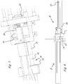
- Figure 1 represents a device for anchoring an overhanging element to a construction 1 according to the invention, in short also called anchoring 1, with two coupling parts, in this case more specifically a male coupling part 2 and a female coupling part 3 shown in an exploded relative position.
- the male coupling part 2 is designed here to be provided in an overhanging element such as a balcony floor, whereas the female coupling part 3 is designed here to be provided in a main structure such as a building.
- the male coupling part 2 essentially consists of a substantially solid, in this case a first metal beam element 4 provided with a threaded bore 6 at one end 5 in the crosscut face, and provided with a second beam element on the opposite end 7 directed transversely to the first beam element 4 leading to a foot 9 protruding on either side of the second beam element 8 having a first foot part 9A and a second foot part 9B.
- a second bore 10 in this case mainly transverse to the bore 6 and parallel to the second beam element 8.
- reinforcement bars 12A-12E are provided.
- five reinforcement bars 12A to 12E are concerned here, whereby the reinforcement bars 12A and 12B are positioned in line with the first foot part 9A and second foot part 9B respectively, and whereby the reinforcement bar 12C is provided higher and in line with the first beam element 4.
- the two reinforcement bars 12D and 12E are essentially provided between the reinforcement bars 12A and 12B here, but near the male coupling part 2 they evolve upward alongside the first beam element 4 of the male coupling part 2.
- the female coupling part 3 designed to be provided in a main structure such as for example a building, comprises a sleeve 13 with an access opening 14 on one side.
- the sleeve 13 is provided with two laterally protruding shoulder plates 15 which are connected to a massive structure 16.
- Said massive structure 16 essentially consists of an outer wall 17 and an inner wall 18 which are mutually connected by means of two side walls 19.
- the outer wall 17 is designed here as a substantially rectangular massive thick plate 20 in which is provided a rectangular recess 22, centrally to the edge 21 which is located at the top when in use.
- the shoulder plates 15 are connected to the outer wall 17, such that the rectangular recess 22 is provided in the extension of the sleeve 13.
- the outer wall 17 is, still seen in the position of use, provided with two passages at the bottom, not visibly displayed here, and in cooperation therewith with two sleeves 23 which each extend as of the outer wall 17 up to a distance thereof in the direction of the male coupling part 2.
- the punches 24 essentially consist of rod elements 26 whose position can be adjusted.
- the inner wall 18 is designed as a massive thick plate 27 as well here, provided at the bottom with a protruding shoulder 28A and 28B on either side.
- the inner wall 18 is provided centrally and, when in use essentially at the top, with a bore through which a bolt 29 is fed, designed to cooperate with the bore 6 in the male coupling part 2.
- the inner wall 18 is provided with bushes 30A-30E which serve as coupling means for reinforcement bars 31A-31E.
- reinforcement bars 31A-31E are provided.
- Two reinforcement bars 31A and 31B are concerned here, in line with the protruding shoulder 28A and 28B respectively, and centrally therebetween reinforcement bar 31C, all of them in conjunction with accompanying bushes 30A, 30B and 30C respectively.
- the two side walls 19 rigidly and securely connect the outer wall 17 to the inner wall 18.
- the punches 24 extend as of the contact plates 25 and through bores provided in the inner wall 18, where the punches 24 are provided with an end plate.
- the punches 24A and 24B in this embodiment comprise separate spacers 33A and 33B in the shape of blocks. These spacers 33A and 33B, in a mounted and activated state, are provided between the rod elements 26 on the one hand, and adjusting nuts 34A and 34B on the other hand.
- the side walls 19 are each provided with two coupling parts 35 with a bore 36.
- This is based on a main structure A which is a building A in this case, built of supporting walls 37 on which are provided prefabricated concrete vaults or wide floor boards 38.
- the female coupling part 3 Before pouring the so-called mixed concrete layer 39, the female coupling part 3 is put in place, either or not before the reinforcement bars 31 are provided.
- the outer wall 17 is placed with the side directed away from the inner wall 18 predominantly in line with the side of the supporting wall 37 directed to the inside of the main structure.
- the female coupling part 3 is placed in such a manner that, afterwards, the further construction of the supporting wall 37 is only just not hindered.
- the sleeves 23 and the punches 24 thereby extend through the supporting wall 37.
- the outer wall 17 of the female coupling part 3, with its side turned away from the inner wall 18, is placed predominantly in line with the side of the supporting wall 37 which is directed to the outside of the main structure, i.e. the female coupling part 3 is then provided such that the application of the insulating layer 40 is only just not hindered.
- the female coupling part 3 is connected to the floor slab 38, in this case by feeding screws through the bores 36 in the coupling parts 35 on the side walls 19.
- the reinforcement bars 31 are placed in proper cooperation with the bushes 30, such that a purposeful transfer of forces is obtained.
- the bolt 29 is situated higher than the upper surface of the pressure layer 39.
- the main structure A can be built up further, and even the optional application of an insulating layer 40 and the masonry of the outer wall 41 can be carried out before applying the overhanging element B, in this case a balcony floor B, to the main structure A.
- an insulating layer 40 and the masonry of the outer wall 41 can be carried out before applying the overhanging element B, in this case a balcony floor B, to the main structure A.
- the overhanging element B can be supplied for example with the aid of a crane.
- the overhanging element B in this case a prefabricated balcony floor B, is provided with two male coupling parts 2 here as explained above.
- each male coupling part 2 is all being held in the concrete of the balcony floor B, such that a solid and durable connection is provided for between the male coupling part 2 and the balcony floor B.
- the second beam element 8 and the foot 9 can be regarded as a connection basis of the male coupling part 2.
- the first beam element 4 can be regarded as a force transmission and the threaded bore 6 as a part of mechanical coupling means between the coupling parts 2 and 3.
- a crane brings the balcony floor B into a position near the female coupling parts 3 concerned, provided at an appropriate distance from one another in the main structure 1 in the manner described above.
- the first beam elements 4 reach with the bore 6 up to the bolts 29 which are screwed down.
- the length of the beam element 4, i.e. the distance D between the part of the male coupling part 2 incorporated in the concrete of the balcony element B, in this case the second beam element 8 and the foot 9 on the one hand, and the access opening of the bore 6 on the other hand, is such that the thickness of the outer wall 41 and of the inner wall or supporting wall 37 and the intermediate insulating layer 40 and the air cavity can be bridged, one and another in such a way that the mechanical connection within the main structure A can be established.
- This distance D or length of the first beam element 4 of the male coupling part 2 amounts to at least the thickness of the applied insulating layer 40 plus the distance between the end face of the first beam element 4 and the support point, here embodied as a pin 11.
- this distance D will amount to at least ten centimetres.
- the threaded bore 6 on the one hand and the bolt 29 on the other hand are in this case the mechanical coupling means between the coupling parts 2 and 3.
- the level or height of the first beam elements 4 and consequently of the balcony floor B can be adjusted by adjusting the pins 11.
- the extent to which the punches 24 protrude forward can be adjusted by operating the as yet still accessible end plates 32 of the punches 24 on site.
- the force distribution is such that the punches 24 are exposed to pressure and vice versa exert pressure on the foot parts 9A and 9B, whereas the bolt 29 and the first beam element 4 are subject to tensile forces and shear forces.
- FIGS 5 to 7 show an alternative embodiment which mainly differs from the embodiment according to figures 1 to 4 in that only one adjustable punch 24 is provided, centrally in this case and under the first beam element 4.
- the punch 24 is provided with one accompanying sleeve 23 through which the adjustable punch 24 is fed, with a contact plate 25 on the side directed towards the male coupling part 2, here also with a substantially truncated circular shape.
- the punch 24 mainly consists of a rod element 26 on the one hand whose position can be adjusted, and of a bolt 42 on the other hand.
- the punch 24 does not comprise a separate spacer 33 in this case, but the rod element 26 with an outer diameter of for example 32 millimetres is embodied in one piece and can be freely moved through a wider passage in the inner wall 18.
- said passage has an inner diameter of for example 40 millimetres.
- this passage is also provided with internal thread.
- the rod element 26 or the so-called push rod 26, when at rest, is freely fed through the passage in the plate 18 into the required position.
- the punch 24 can be operated via the inwardly facing side of the inner wall 18.
- This variant embodiment provides a safe assembly area during the coupling of the coupling parts, i.e. the male coupling part 2 and the female coupling part 3.
Landscapes
- Engineering & Computer Science (AREA)
- Architecture (AREA)
- Physics & Mathematics (AREA)
- Electromagnetism (AREA)
- Civil Engineering (AREA)
- Structural Engineering (AREA)
- Joining Of Building Structures In Genera (AREA)
- Clamps And Clips (AREA)
Claims (9)
- Vorrichtung zur Verankerung eines auskragenden Elements (B) an einer Konstruktion (A), wobei die Vorrichtung zwei Koppelteile (2, 3) umfasst, wovon ein Koppelteil zur Verbindung mit dem auskragenden Element (B) geeignet ist, während das andere zur Verbindung mit der Konstruktion (A) geeignet ist, und wobei die Koppelteile (2, 3) mit mechanischen Koppelmitteln (6, 29) versehen sind und wobei mindestens eines der Koppelteile (2, 3) ein frei vorragendes Element (4) umfasst, dessen Länge größer als zehn Zentimeter ist, wobei die Koppelteile (2, 3) ein männliches Koppelteil (2) und ein weibliches Koppelteil (3) betreffen, wobei das männliche Koppelteil (2) das frei vorragende Element (4) umfasst, beispielsweise in Form eines ersten Balkenelements (4), das an einem Ende (5) mit mechanischen Koppelmitteln versehen ist und an dem entgegengesetzten Ende (7) mit einer Verbindungsbasis versehen ist, dadurch gekennzeichnet, dass das männliche Koppelteil (2) an dem auskragenden Element (B) vorgesehen ist, während das weibliche Koppelteil (3) an der Konstruktion (A) vorgesehen ist.
- Vorrichtung nach Anspruch 1, dadurch gekennzeichnet, dass die Koppelteile (2, 3) ein männliches Koppelteil (2) umfassen, das im Wesentlichen aus einem ersten, vorwiegend massiven Balkenelement (4) aus Metall besteht, das an einem Ende (5) in der stirnseitigen Fläche mit einer Gewindebohrung (6) versehen ist, und dass das entgegengesetzte Ende (7) mit einer Verbindungsbasis versehen ist, die ein quer zu dem ersten Balkenelement (4) gerichtetes Balkenelement (8) umfasst, das zu einem an beiden Seiten des zweiten Balkenelements (8) vorragenden Fuß (9) mit einem ersten Fußteil (9A) und einem zweiten Fußteil (9B) führt, wobei die Länge des ersten Balkenelements (4) mindestens zehn Zentimeter beträgt.
- Vorrichtung nach Anspruch 1 oder 2, dadurch gekennzeichnet, dass zwischen den Enden (5, 7) des ersten Balkenelements (4) eine zweite Bohrung (10) vorgesehen ist.
- Vorrichtung nach einem oder mehreren der Ansprüche 1 bis 3, dadurch gekennzeichnet, dass das weibliche Koppelteil (3) mit mechanischen Koppelmitteln (29), die mit den an den Enden (5) des vorragenden Elements (4) versehenen mechanischen Koppelmitteln zusammenwirken können, und mit einer oder mehreren Stützen (24) oder dergleichen, die mit der an dem entgegengesetzten Ende (7) des vorragenden Elements (4) vorgesehenen Verbindungsbasis zusammenwirken können, versehen ist.
- Vorrichtung nach Anspruch 4, dadurch gekennzeichnet, dass sie eine massive Struktur (16) umfasst, die im Wesentlichen aus einer Außenwand (17) und einer Innenwand (18) besteht, die mittels zweier Seitenwände (19) miteinander verbunden sind, wobei, alles aus einer Anwendungsposition betrachtet, die Außenwand (17) in Nähe der Oberkante mit einer Ausnehmung (22) versehen ist und unten mit mindestens einem Durchgang versehen ist, durch den eine Stütze (24) vorgesehen ist oder werden kann, und wobei die Innenwand (18) unten an beiden Seiten mit einer vorragenden Schulter (28A, 28B) versehen ist, und zentral, im Wesentlichen oben, mit mechanischen Koppelmitteln, beispielsweise einer Bohrung zum Einführen eines Bolzens 29, versehen ist.
- Vorrichtung nach Anspruch 4 oder 5, dadurch gekennzeichnet, dass, im Zusammenwirken mit einem Durchgang in der Außenwand (17), eine Hülse (23) vorgesehen ist, durch die eine Stütze (24) hindurchgeführt werden kann, wobei die Stütze (24), in dem Raum zwischen der Außenwand (17) und der Innenwand (18), im Wesentlichen aus einem Stabelement (26) besteht.
- Verfahren zur Verankerung eines auskragenden Elements an einer Konstruktion unter Anwendung einer Vorrichtung nach einem der Ansprüche 1 bis 6, dadurch gekennzeichnet, dass beim Bau der Konstruktion (A) die Anbringung einer Dämmschicht (41) und/oder die Anbringung einer Fassadenbekleidung der Verankerung des auskragenden Elements (B) an der Konstruktion (A) vorausgeht.
- Verfahren nach Anspruch 7, dadurch gekennzeichnet, dass in dem Prozess der Verankerung des auskragenden Elements (B) an der Konstruktion (A) ein frei vorragendes Element (4), das an dem vorgefertigten auskragenden Element (8) vorgesehen ist und eine Länge von mehr als zehn Zentimetern aufweist, durch die eventuelle Dämmschicht (41) und/oder, falls erforderlich, durch die Fassadenbekleidung hindurchgeführt wird, um danach mittels der Innenseite der Konstruktion (A) an diese letztere gekoppelt zu werden.
- Verfahren nach Anspruch 7 oder 8, dadurch gekennzeichnet, dass ein Koppelteil mit dem auskragenden Element (B) verbunden wird, während das andere Koppelteil mit der Konstruktion (A) während des Baus davon verbunden wird, und wobei, eventuell nach der hauptsächlichen Anbringung der Dämmschicht (41) und eventuell nach der hauptsächlichen Fertigstellung der Fassadenbekleidung, das auskragende Element (B) mit der Konstruktion (A) verbunden wird, indem die Koppelteile (2, 3) mittels der mechanischen Koppelmittel (6, 29) miteinander verbunden werden, nachdem ein frei vorragendes Element (4) von mindestens einem der Koppelteile (2, 3) mit einer maximalen Länge von mehr als zehn Zentimetern durch die Fassade hindurchgeführt worden ist.
Priority Applications (2)
| Application Number | Priority Date | Filing Date | Title |
|---|---|---|---|
| PL15721839T PL3134586T3 (pl) | 2014-04-22 | 2015-03-25 | Urządzenie i sposób kotwienia wystającego elementu do konstrukcji |
| RSP20191030 RS59366B1 (sr) | 2014-04-22 | 2015-03-25 | Uređaj i postupak za pričvršćivanje visećeg elementa za konstrukciju |
Applications Claiming Priority (2)
| Application Number | Priority Date | Filing Date | Title |
|---|---|---|---|
| BE2014/0277A BE1021992B1 (nl) | 2014-04-22 | 2014-04-22 | Inrichting en werkwijze voor het verankeren van een uitkragend element aan een constructie |
| PCT/IB2015/052182 WO2015162507A1 (en) | 2014-04-22 | 2015-03-25 | Device and method for anchoring an overhanging element to a construction |
Publications (2)
| Publication Number | Publication Date |
|---|---|
| EP3134586A1 EP3134586A1 (de) | 2017-03-01 |
| EP3134586B1 true EP3134586B1 (de) | 2019-05-08 |
Family
ID=51014138
Family Applications (1)
| Application Number | Title | Priority Date | Filing Date |
|---|---|---|---|
| EP15721839.7A Active EP3134586B1 (de) | 2014-04-22 | 2015-03-25 | Vorrichtung und verfahren zur verankerung eines überhängenden elements an eine konstruktion |
Country Status (13)
| Country | Link |
|---|---|
| US (1) | US10227769B2 (de) |
| EP (1) | EP3134586B1 (de) |
| AU (1) | AU2015249488B2 (de) |
| BE (1) | BE1021992B1 (de) |
| DK (1) | DK3134586T3 (de) |
| EA (1) | EA032184B1 (de) |
| ES (1) | ES2739708T3 (de) |
| HU (1) | HUE044651T2 (de) |
| LT (1) | LT3134586T (de) |
| PL (1) | PL3134586T3 (de) |
| PT (1) | PT3134586T (de) |
| RS (1) | RS59366B1 (de) |
| WO (1) | WO2015162507A1 (de) |
Families Citing this family (1)
| Publication number | Priority date | Publication date | Assignee | Title |
|---|---|---|---|---|
| FI130872B1 (fi) * | 2018-05-31 | 2024-04-30 | Flow Modules Oy | Järjestely ja kiinnitysmenetelmä elementin kiinnityksen toteuttamiseksi ontelolaattaan |
Family Cites Families (12)
| Publication number | Priority date | Publication date | Assignee | Title |
|---|---|---|---|---|
| US4781006A (en) * | 1986-11-10 | 1988-11-01 | Haynes Harvey H | Bolted chord bar connector for concrete construction |
| DE19602306B4 (de) * | 1996-01-23 | 2004-02-19 | Schöck Entwicklungsgesellschaft mbH | Tragvorrichtung |
| DE10007450A1 (de) * | 2000-02-18 | 2001-08-30 | Mea Meisinger Stahl & Kunststo | Montageträgersystem sowie Verfahren zur Befestigung eines Fertigbauteils an einem Gebäudeteil unter Verwendung des Montageträgersystems |
| FI20002303A (fi) * | 2000-10-18 | 2002-04-19 | Teraespeikko Oy | Konsoli rakenneosan, kuten betonielementtipalkin, tukemiseksi betonipilariin tai vastaavaan rakennuksen tukirakenteeseen |
| US6679017B2 (en) * | 2002-01-15 | 2004-01-20 | Woodruff, Iii James F. | Preformed bolt-on haunch system |
| NO321443B1 (no) * | 2004-06-30 | 2006-05-08 | Sb Produksjon As | Sammenforingssystem, enkeltelementer og fremgangsmate for bruk av dette |
| NO323943B1 (no) * | 2005-10-13 | 2007-07-23 | Sb Produksjon As | Sammenfoyningssystem og anvendelse av dette |
| US20090263189A9 (en) * | 2007-04-13 | 2009-10-22 | Kari Koivunen | Joint for reinforced concrete pile sections |
| NL1035733C2 (nl) * | 2008-07-22 | 2010-01-25 | Frank Boudewijn Smits | Haakanker ten behoeve van het ophangen van een balkon of vloerplaat aan een gebouw. |
| GB2507365B (en) * | 2013-04-22 | 2014-10-22 | Sapphire Balustrades Ltd | Balcony |
| US8950133B2 (en) * | 2013-04-29 | 2015-02-10 | Peikko Group Oy | Bracket and an arrangement for supporting a precast slab element of concrete on a precast structure element of concrete |
| US8973317B2 (en) * | 2013-05-13 | 2015-03-10 | James Larkin | Thermal break for concrete slab edges and balconies |
-
2014
- 2014-04-22 BE BE2014/0277A patent/BE1021992B1/nl not_active IP Right Cessation
-
2015
- 2015-03-25 US US15/120,631 patent/US10227769B2/en not_active Expired - Fee Related
- 2015-03-25 PT PT15721839T patent/PT3134586T/pt unknown
- 2015-03-25 PL PL15721839T patent/PL3134586T3/pl unknown
- 2015-03-25 DK DK15721839.7T patent/DK3134586T3/da active
- 2015-03-25 RS RSP20191030 patent/RS59366B1/sr unknown
- 2015-03-25 EA EA201691474A patent/EA032184B1/ru not_active IP Right Cessation
- 2015-03-25 WO PCT/IB2015/052182 patent/WO2015162507A1/en active Application Filing
- 2015-03-25 AU AU2015249488A patent/AU2015249488B2/en not_active Ceased
- 2015-03-25 HU HUE15721839 patent/HUE044651T2/hu unknown
- 2015-03-25 EP EP15721839.7A patent/EP3134586B1/de active Active
- 2015-03-25 LT LTEP15721839.7T patent/LT3134586T/lt unknown
- 2015-03-25 ES ES15721839T patent/ES2739708T3/es active Active
Non-Patent Citations (1)
| Title |
|---|
| None * |
Also Published As
| Publication number | Publication date |
|---|---|
| WO2015162507A1 (en) | 2015-10-29 |
| RS59366B1 (sr) | 2019-11-29 |
| US10227769B2 (en) | 2019-03-12 |
| US20170009441A1 (en) | 2017-01-12 |
| AU2015249488B2 (en) | 2019-09-12 |
| LT3134586T (lt) | 2019-09-10 |
| BE1021992B1 (nl) | 2016-02-02 |
| PL3134586T3 (pl) | 2020-01-31 |
| PT3134586T (pt) | 2019-09-06 |
| DK3134586T3 (da) | 2019-08-12 |
| EP3134586A1 (de) | 2017-03-01 |
| EA201691474A1 (ru) | 2017-05-31 |
| HUE044651T2 (hu) | 2019-11-28 |
| ES2739708T3 (es) | 2020-02-03 |
| AU2015249488A1 (en) | 2016-09-01 |
| EA032184B1 (ru) | 2019-04-30 |
Similar Documents
| Publication | Publication Date | Title |
|---|---|---|
| EP2261430B1 (de) | Bau eines Überhangs | |
| WO2011071524A1 (en) | Green from for the construction of load bearing concrete structures | |
| CA2673813A1 (en) | Joist hanger for icf wall systems | |
| GB2460674A (en) | Masonry bracket | |
| WO2015011641A1 (en) | Semi rigid precast wall system | |
| US20160289982A1 (en) | Formwork element | |
| KR20120085641A (ko) | 보 및 슬래브 거푸집 조립 구조 및 이를 이용한 보 및 슬래브 구조물 시공 방법 | |
| CN114135027B (zh) | 新复合隔热层建筑模板组 | |
| US20040068945A1 (en) | Concrete home building | |
| KR101847827B1 (ko) | 건축용 외장 패널 고정장치와, 단열재와 결합된 거푸집을 이용한 건축물의 외벽 및 건축용 외장 패널 시공방법 | |
| KR20130059010A (ko) | 저모멘트존을 이용한 pc기둥 접합구조 | |
| EP3134586B1 (de) | Vorrichtung und verfahren zur verankerung eines überhängenden elements an eine konstruktion | |
| KR101668521B1 (ko) | 다층 건축물의 지하층 콘크리트의 시공방법 | |
| RU171934U1 (ru) | Конструкция усиления растянутой зоны сборной железобетонной многопустотной плиты | |
| CN105040823A (zh) | 一种剪刀楼梯的隔墙板与楼层梁的连接结构及其施工方法 | |
| US20100037538A1 (en) | Temporary adjustable support brace | |
| EP3409854A1 (de) | Verbindung und ausrichtung von bauelementen | |
| GB2495319A (en) | Beam and slab floor construction | |
| KR100860592B1 (ko) | Pc블럭 적층시공용 가설구조 | |
| KR101308055B1 (ko) | 저모멘트존을 이용한 pc기둥 접합구조 | |
| JP2021085270A (ja) | 壁パネルの建て込み方法 | |
| GB2574172A (en) | Prefabricated block wall | |
| JP7479228B2 (ja) | プレキャストコンクリート板、およびコンクリート構造物の構築方法 | |
| US20170254070A1 (en) | Wall Construction | |
| CN217871830U (zh) | 楼层板上电缆桥架预留洞口的浇筑模板体系 |
Legal Events
| Date | Code | Title | Description |
|---|---|---|---|
| STAA | Information on the status of an ep patent application or granted ep patent |
Free format text: STATUS: THE INTERNATIONAL PUBLICATION HAS BEEN MADE |
|
| PUAI | Public reference made under article 153(3) epc to a published international application that has entered the european phase |
Free format text: ORIGINAL CODE: 0009012 |
|
| STAA | Information on the status of an ep patent application or granted ep patent |
Free format text: STATUS: REQUEST FOR EXAMINATION WAS MADE |
|
| 17P | Request for examination filed |
Effective date: 20161122 |
|
| AK | Designated contracting states |
Kind code of ref document: A1 Designated state(s): AL AT BE BG CH CY CZ DE DK EE ES FI FR GB GR HR HU IE IS IT LI LT LU LV MC MK MT NL NO PL PT RO RS SE SI SK SM TR |
|
| AX | Request for extension of the european patent |
Extension state: BA ME |
|
| DAV | Request for validation of the european patent (deleted) | ||
| DAX | Request for extension of the european patent (deleted) | ||
| STAA | Information on the status of an ep patent application or granted ep patent |
Free format text: STATUS: EXAMINATION IS IN PROGRESS |
|
| 17Q | First examination report despatched |
Effective date: 20170823 |
|
| GRAP | Despatch of communication of intention to grant a patent |
Free format text: ORIGINAL CODE: EPIDOSNIGR1 |
|
| STAA | Information on the status of an ep patent application or granted ep patent |
Free format text: STATUS: GRANT OF PATENT IS INTENDED |
|
| INTG | Intention to grant announced |
Effective date: 20181123 |
|
| GRAS | Grant fee paid |
Free format text: ORIGINAL CODE: EPIDOSNIGR3 |
|
| GRAA | (expected) grant |
Free format text: ORIGINAL CODE: 0009210 |
|
| STAA | Information on the status of an ep patent application or granted ep patent |
Free format text: STATUS: THE PATENT HAS BEEN GRANTED |
|
| AK | Designated contracting states |
Kind code of ref document: B1 Designated state(s): AL AT BE BG CH CY CZ DE DK EE ES FI FR GB GR HR HU IE IS IT LI LT LU LV MC MK MT NL NO PL PT RO RS SE SI SK SM TR |
|
| REG | Reference to a national code |
Ref country code: GB Ref legal event code: FG4D |
|
| REG | Reference to a national code |
Ref country code: CH Ref legal event code: EP Ref country code: AT Ref legal event code: REF Ref document number: 1130337 Country of ref document: AT Kind code of ref document: T Effective date: 20190515 |
|
| REG | Reference to a national code |
Ref country code: DE Ref legal event code: R096 Ref document number: 602015029829 Country of ref document: DE Ref country code: IE Ref legal event code: FG4D |
|
| REG | Reference to a national code |
Ref country code: DK Ref legal event code: T3 Effective date: 20190808 |
|
| REG | Reference to a national code |
Ref country code: NL Ref legal event code: FP |
|
| REG | Reference to a national code |
Ref country code: CH Ref legal event code: NV Representative=s name: ORITI PATENTS - FRANCO ORITI, CH |
|
| REG | Reference to a national code |
Ref country code: SE Ref legal event code: TRGR |
|
| REG | Reference to a national code |
Ref country code: PT Ref legal event code: SC4A Ref document number: 3134586 Country of ref document: PT Date of ref document: 20190906 Kind code of ref document: T Free format text: AVAILABILITY OF NATIONAL TRANSLATION Effective date: 20190819 |
|
| REG | Reference to a national code |
Ref country code: NO Ref legal event code: T2 Effective date: 20190508 |
|
| REG | Reference to a national code |
Ref country code: GR Ref legal event code: EP Ref document number: 20190402401 Country of ref document: GR Effective date: 20191016 |
|
| PG25 | Lapsed in a contracting state [announced via postgrant information from national office to epo] |
Ref country code: HR Free format text: LAPSE BECAUSE OF FAILURE TO SUBMIT A TRANSLATION OF THE DESCRIPTION OR TO PAY THE FEE WITHIN THE PRESCRIBED TIME-LIMIT Effective date: 20190508 Ref country code: AL Free format text: LAPSE BECAUSE OF FAILURE TO SUBMIT A TRANSLATION OF THE DESCRIPTION OR TO PAY THE FEE WITHIN THE PRESCRIBED TIME-LIMIT Effective date: 20190508 |
|
| REG | Reference to a national code |
Ref country code: SK Ref legal event code: T3 Ref document number: E 31892 Country of ref document: SK |
|
| REG | Reference to a national code |
Ref country code: HU Ref legal event code: AG4A Ref document number: E044651 Country of ref document: HU |
|
| PG25 | Lapsed in a contracting state [announced via postgrant information from national office to epo] |
Ref country code: BG Free format text: LAPSE BECAUSE OF FAILURE TO SUBMIT A TRANSLATION OF THE DESCRIPTION OR TO PAY THE FEE WITHIN THE PRESCRIBED TIME-LIMIT Effective date: 20190808 Ref country code: LV Free format text: LAPSE BECAUSE OF FAILURE TO SUBMIT A TRANSLATION OF THE DESCRIPTION OR TO PAY THE FEE WITHIN THE PRESCRIBED TIME-LIMIT Effective date: 20190508 |
|
| PG25 | Lapsed in a contracting state [announced via postgrant information from national office to epo] |
Ref country code: EE Free format text: LAPSE BECAUSE OF FAILURE TO SUBMIT A TRANSLATION OF THE DESCRIPTION OR TO PAY THE FEE WITHIN THE PRESCRIBED TIME-LIMIT Effective date: 20190508 Ref country code: RO Free format text: LAPSE BECAUSE OF FAILURE TO SUBMIT A TRANSLATION OF THE DESCRIPTION OR TO PAY THE FEE WITHIN THE PRESCRIBED TIME-LIMIT Effective date: 20190508 |
|
| REG | Reference to a national code |
Ref country code: ES Ref legal event code: FG2A Ref document number: 2739708 Country of ref document: ES Kind code of ref document: T3 Effective date: 20200203 |
|
| REG | Reference to a national code |
Ref country code: DE Ref legal event code: R097 Ref document number: 602015029829 Country of ref document: DE |
|
| PG25 | Lapsed in a contracting state [announced via postgrant information from national office to epo] |
Ref country code: SM Free format text: LAPSE BECAUSE OF FAILURE TO SUBMIT A TRANSLATION OF THE DESCRIPTION OR TO PAY THE FEE WITHIN THE PRESCRIBED TIME-LIMIT Effective date: 20190508 |
|
| PLBE | No opposition filed within time limit |
Free format text: ORIGINAL CODE: 0009261 |
|
| STAA | Information on the status of an ep patent application or granted ep patent |
Free format text: STATUS: NO OPPOSITION FILED WITHIN TIME LIMIT |
|
| 26N | No opposition filed |
Effective date: 20200211 |
|
| PG25 | Lapsed in a contracting state [announced via postgrant information from national office to epo] |
Ref country code: SI Free format text: LAPSE BECAUSE OF FAILURE TO SUBMIT A TRANSLATION OF THE DESCRIPTION OR TO PAY THE FEE WITHIN THE PRESCRIBED TIME-LIMIT Effective date: 20190508 |
|
| PGFP | Annual fee paid to national office [announced via postgrant information from national office to epo] |
Ref country code: FI Payment date: 20210318 Year of fee payment: 7 Ref country code: CZ Payment date: 20210318 Year of fee payment: 7 Ref country code: IE Payment date: 20210315 Year of fee payment: 7 Ref country code: GR Payment date: 20210324 Year of fee payment: 7 Ref country code: FR Payment date: 20210315 Year of fee payment: 7 Ref country code: LT Payment date: 20210316 Year of fee payment: 7 Ref country code: NO Payment date: 20210322 Year of fee payment: 7 Ref country code: NL Payment date: 20210315 Year of fee payment: 7 Ref country code: PT Payment date: 20210324 Year of fee payment: 7 Ref country code: MC Payment date: 20210323 Year of fee payment: 7 Ref country code: LU Payment date: 20210315 Year of fee payment: 7 |
|
| PGFP | Annual fee paid to national office [announced via postgrant information from national office to epo] |
Ref country code: BE Payment date: 20210315 Year of fee payment: 7 Ref country code: AT Payment date: 20210322 Year of fee payment: 7 Ref country code: GB Payment date: 20210315 Year of fee payment: 7 Ref country code: DK Payment date: 20210322 Year of fee payment: 7 Ref country code: TR Payment date: 20210318 Year of fee payment: 7 Ref country code: RS Payment date: 20210319 Year of fee payment: 7 Ref country code: SE Payment date: 20210315 Year of fee payment: 7 Ref country code: PL Payment date: 20210317 Year of fee payment: 7 Ref country code: DE Payment date: 20210322 Year of fee payment: 7 |
|
| PGFP | Annual fee paid to national office [announced via postgrant information from national office to epo] |
Ref country code: SK Payment date: 20210318 Year of fee payment: 7 |
|
| PGFP | Annual fee paid to national office [announced via postgrant information from national office to epo] |
Ref country code: IT Payment date: 20210329 Year of fee payment: 7 |
|
| PGFP | Annual fee paid to national office [announced via postgrant information from national office to epo] |
Ref country code: HU Payment date: 20210412 Year of fee payment: 7 Ref country code: CH Payment date: 20210420 Year of fee payment: 7 Ref country code: ES Payment date: 20210615 Year of fee payment: 7 |
|
| REG | Reference to a national code |
Ref country code: AT Ref legal event code: UEP Ref document number: 1130337 Country of ref document: AT Kind code of ref document: T Effective date: 20190508 |
|
| PG25 | Lapsed in a contracting state [announced via postgrant information from national office to epo] |
Ref country code: MT Free format text: LAPSE BECAUSE OF FAILURE TO SUBMIT A TRANSLATION OF THE DESCRIPTION OR TO PAY THE FEE WITHIN THE PRESCRIBED TIME-LIMIT Effective date: 20190508 Ref country code: CY Free format text: LAPSE BECAUSE OF FAILURE TO SUBMIT A TRANSLATION OF THE DESCRIPTION OR TO PAY THE FEE WITHIN THE PRESCRIBED TIME-LIMIT Effective date: 20190508 |
|
| PG25 | Lapsed in a contracting state [announced via postgrant information from national office to epo] |
Ref country code: MK Free format text: LAPSE BECAUSE OF FAILURE TO SUBMIT A TRANSLATION OF THE DESCRIPTION OR TO PAY THE FEE WITHIN THE PRESCRIBED TIME-LIMIT Effective date: 20190508 Ref country code: IS Free format text: LAPSE BECAUSE OF FAILURE TO SUBMIT A TRANSLATION OF THE DESCRIPTION OR TO PAY THE FEE WITHIN THE PRESCRIBED TIME-LIMIT Effective date: 20190908 |
|
| REG | Reference to a national code |
Ref country code: DE Ref legal event code: R119 Ref document number: 602015029829 Country of ref document: DE |
|
| REG | Reference to a national code |
Ref country code: FI Ref legal event code: MAE |
|
| REG | Reference to a national code |
Ref country code: NO Ref legal event code: MMEP Ref country code: DK Ref legal event code: EBP Effective date: 20220331 |
|
| REG | Reference to a national code |
Ref country code: LT Ref legal event code: MM4D Effective date: 20220325 |
|
| PG25 | Lapsed in a contracting state [announced via postgrant information from national office to epo] |
Ref country code: PT Free format text: LAPSE BECAUSE OF NON-PAYMENT OF DUE FEES Effective date: 20220926 Ref country code: MC Free format text: LAPSE BECAUSE OF NON-PAYMENT OF DUE FEES Effective date: 20220331 Ref country code: FI Free format text: LAPSE BECAUSE OF NON-PAYMENT OF DUE FEES Effective date: 20220325 Ref country code: CZ Free format text: LAPSE BECAUSE OF NON-PAYMENT OF DUE FEES Effective date: 20220325 |
|
| REG | Reference to a national code |
Ref country code: CH Ref legal event code: PL |
|
| REG | Reference to a national code |
Ref country code: NL Ref legal event code: MM Effective date: 20220401 |
|
| REG | Reference to a national code |
Ref country code: SK Ref legal event code: MM4A Ref document number: E 31892 Country of ref document: SK Effective date: 20220325 |
|
| REG | Reference to a national code |
Ref country code: AT Ref legal event code: MM01 Ref document number: 1130337 Country of ref document: AT Kind code of ref document: T Effective date: 20220325 |
|
| GBPC | Gb: european patent ceased through non-payment of renewal fee |
Effective date: 20220325 |
|
| REG | Reference to a national code |
Ref country code: BE Ref legal event code: MM Effective date: 20220331 |
|
| PG25 | Lapsed in a contracting state [announced via postgrant information from national office to epo] |
Ref country code: SK Free format text: LAPSE BECAUSE OF NON-PAYMENT OF DUE FEES Effective date: 20220325 Ref country code: SE Free format text: LAPSE BECAUSE OF NON-PAYMENT OF DUE FEES Effective date: 20220326 Ref country code: RS Free format text: LAPSE BECAUSE OF NON-PAYMENT OF DUE FEES Effective date: 20220325 Ref country code: NO Free format text: LAPSE BECAUSE OF NON-PAYMENT OF DUE FEES Effective date: 20220331 Ref country code: NL Free format text: LAPSE BECAUSE OF NON-PAYMENT OF DUE FEES Effective date: 20220401 Ref country code: LU Free format text: LAPSE BECAUSE OF NON-PAYMENT OF DUE FEES Effective date: 20220325 Ref country code: LT Free format text: LAPSE BECAUSE OF NON-PAYMENT OF DUE FEES Effective date: 20220325 Ref country code: LI Free format text: LAPSE BECAUSE OF NON-PAYMENT OF DUE FEES Effective date: 20220331 Ref country code: IE Free format text: LAPSE BECAUSE OF NON-PAYMENT OF DUE FEES Effective date: 20220325 Ref country code: HU Free format text: LAPSE BECAUSE OF NON-PAYMENT OF DUE FEES Effective date: 20220326 Ref country code: GB Free format text: LAPSE BECAUSE OF NON-PAYMENT OF DUE FEES Effective date: 20220325 Ref country code: FR Free format text: LAPSE BECAUSE OF NON-PAYMENT OF DUE FEES Effective date: 20220331 Ref country code: DE Free format text: LAPSE BECAUSE OF NON-PAYMENT OF DUE FEES Effective date: 20221001 Ref country code: CH Free format text: LAPSE BECAUSE OF NON-PAYMENT OF DUE FEES Effective date: 20220331 Ref country code: AT Free format text: LAPSE BECAUSE OF NON-PAYMENT OF DUE FEES Effective date: 20220325 |
|
| PG25 | Lapsed in a contracting state [announced via postgrant information from national office to epo] |
Ref country code: GR Free format text: LAPSE BECAUSE OF NON-PAYMENT OF DUE FEES Effective date: 20221006 Ref country code: BE Free format text: LAPSE BECAUSE OF NON-PAYMENT OF DUE FEES Effective date: 20220331 |
|
| PG25 | Lapsed in a contracting state [announced via postgrant information from national office to epo] |
Ref country code: DK Free format text: LAPSE BECAUSE OF NON-PAYMENT OF DUE FEES Effective date: 20220331 |
|
| REG | Reference to a national code |
Ref country code: ES Ref legal event code: FD2A Effective date: 20230509 |
|
| PG25 | Lapsed in a contracting state [announced via postgrant information from national office to epo] |
Ref country code: IT Free format text: LAPSE BECAUSE OF NON-PAYMENT OF DUE FEES Effective date: 20220325 |
|
| PG25 | Lapsed in a contracting state [announced via postgrant information from national office to epo] |
Ref country code: ES Free format text: LAPSE BECAUSE OF NON-PAYMENT OF DUE FEES Effective date: 20220326 |
|
| PG25 | Lapsed in a contracting state [announced via postgrant information from national office to epo] |
Ref country code: PL Free format text: LAPSE BECAUSE OF NON-PAYMENT OF DUE FEES Effective date: 20220325 |