EP3134249B1 - Method of manufacturing laminate and the laminate - Google Patents
Method of manufacturing laminate and the laminate Download PDFInfo
- Publication number
- EP3134249B1 EP3134249B1 EP14725351.2A EP14725351A EP3134249B1 EP 3134249 B1 EP3134249 B1 EP 3134249B1 EP 14725351 A EP14725351 A EP 14725351A EP 3134249 B1 EP3134249 B1 EP 3134249B1
- Authority
- EP
- European Patent Office
- Prior art keywords
- layer
- refraction
- different index
- index
- different
- Prior art date
- Legal status (The legal status is an assumption and is not a legal conclusion. Google has not performed a legal analysis and makes no representation as to the accuracy of the status listed.)
- Active
Links
Images


Classifications
-
- B—PERFORMING OPERATIONS; TRANSPORTING
- B29—WORKING OF PLASTICS; WORKING OF SUBSTANCES IN A PLASTIC STATE IN GENERAL
- B29D—PRODUCING PARTICULAR ARTICLES FROM PLASTICS OR FROM SUBSTANCES IN A PLASTIC STATE
- B29D11/00—Producing optical elements, e.g. lenses or prisms
- B29D11/0073—Optical laminates
-
- B—PERFORMING OPERATIONS; TRANSPORTING
- B29—WORKING OF PLASTICS; WORKING OF SUBSTANCES IN A PLASTIC STATE IN GENERAL
- B29C—SHAPING OR JOINING OF PLASTICS; SHAPING OF MATERIAL IN A PLASTIC STATE, NOT OTHERWISE PROVIDED FOR; AFTER-TREATMENT OF THE SHAPED PRODUCTS, e.g. REPAIRING
- B29C59/00—Surface shaping of articles, e.g. embossing; Apparatus therefor
- B29C59/02—Surface shaping of articles, e.g. embossing; Apparatus therefor by mechanical means, e.g. pressing
- B29C59/026—Surface shaping of articles, e.g. embossing; Apparatus therefor by mechanical means, e.g. pressing of layered or coated substantially flat surfaces
-
- B—PERFORMING OPERATIONS; TRANSPORTING
- B32—LAYERED PRODUCTS
- B32B—LAYERED PRODUCTS, i.e. PRODUCTS BUILT-UP OF STRATA OF FLAT OR NON-FLAT, e.g. CELLULAR OR HONEYCOMB, FORM
- B32B27/00—Layered products comprising a layer of synthetic resin
- B32B27/06—Layered products comprising a layer of synthetic resin as the main or only constituent of a layer, which is next to another layer of the same or of a different material
- B32B27/08—Layered products comprising a layer of synthetic resin as the main or only constituent of a layer, which is next to another layer of the same or of a different material of synthetic resin
-
- B—PERFORMING OPERATIONS; TRANSPORTING
- B32—LAYERED PRODUCTS
- B32B—LAYERED PRODUCTS, i.e. PRODUCTS BUILT-UP OF STRATA OF FLAT OR NON-FLAT, e.g. CELLULAR OR HONEYCOMB, FORM
- B32B3/00—Layered products comprising a layer with external or internal discontinuities or unevennesses, or a layer of non-planar shape; Layered products comprising a layer having particular features of form
- B32B3/26—Layered products comprising a layer with external or internal discontinuities or unevennesses, or a layer of non-planar shape; Layered products comprising a layer having particular features of form characterised by a particular shape of the outline of the cross-section of a continuous layer; characterised by a layer with cavities or internal voids ; characterised by an apertured layer
- B32B3/263—Layered products comprising a layer with external or internal discontinuities or unevennesses, or a layer of non-planar shape; Layered products comprising a layer having particular features of form characterised by a particular shape of the outline of the cross-section of a continuous layer; characterised by a layer with cavities or internal voids ; characterised by an apertured layer characterised by a layer having non-uniform thickness
-
- B—PERFORMING OPERATIONS; TRANSPORTING
- B32—LAYERED PRODUCTS
- B32B—LAYERED PRODUCTS, i.e. PRODUCTS BUILT-UP OF STRATA OF FLAT OR NON-FLAT, e.g. CELLULAR OR HONEYCOMB, FORM
- B32B3/00—Layered products comprising a layer with external or internal discontinuities or unevennesses, or a layer of non-planar shape; Layered products comprising a layer having particular features of form
- B32B3/26—Layered products comprising a layer with external or internal discontinuities or unevennesses, or a layer of non-planar shape; Layered products comprising a layer having particular features of form characterised by a particular shape of the outline of the cross-section of a continuous layer; characterised by a layer with cavities or internal voids ; characterised by an apertured layer
- B32B3/266—Layered products comprising a layer with external or internal discontinuities or unevennesses, or a layer of non-planar shape; Layered products comprising a layer having particular features of form characterised by a particular shape of the outline of the cross-section of a continuous layer; characterised by a layer with cavities or internal voids ; characterised by an apertured layer characterised by an apertured layer, the apertures going through the whole thickness of the layer, e.g. expanded metal, perforated layer, slit layer regular cells B32B3/12
-
- B—PERFORMING OPERATIONS; TRANSPORTING
- B32—LAYERED PRODUCTS
- B32B—LAYERED PRODUCTS, i.e. PRODUCTS BUILT-UP OF STRATA OF FLAT OR NON-FLAT, e.g. CELLULAR OR HONEYCOMB, FORM
- B32B3/00—Layered products comprising a layer with external or internal discontinuities or unevennesses, or a layer of non-planar shape; Layered products comprising a layer having particular features of form
- B32B3/26—Layered products comprising a layer with external or internal discontinuities or unevennesses, or a layer of non-planar shape; Layered products comprising a layer having particular features of form characterised by a particular shape of the outline of the cross-section of a continuous layer; characterised by a layer with cavities or internal voids ; characterised by an apertured layer
- B32B3/30—Layered products comprising a layer with external or internal discontinuities or unevennesses, or a layer of non-planar shape; Layered products comprising a layer having particular features of form characterised by a particular shape of the outline of the cross-section of a continuous layer; characterised by a layer with cavities or internal voids ; characterised by an apertured layer characterised by a layer formed with recesses or projections, e.g. hollows, grooves, protuberances, ribs
-
- B—PERFORMING OPERATIONS; TRANSPORTING
- B42—BOOKBINDING; ALBUMS; FILES; SPECIAL PRINTED MATTER
- B42D—BOOKS; BOOK COVERS; LOOSE LEAVES; PRINTED MATTER CHARACTERISED BY IDENTIFICATION OR SECURITY FEATURES; PRINTED MATTER OF SPECIAL FORMAT OR STYLE NOT OTHERWISE PROVIDED FOR; DEVICES FOR USE THEREWITH AND NOT OTHERWISE PROVIDED FOR; MOVABLE-STRIP WRITING OR READING APPARATUS
- B42D25/00—Information-bearing cards or sheet-like structures characterised by identification or security features; Manufacture thereof
- B42D25/20—Information-bearing cards or sheet-like structures characterised by identification or security features; Manufacture thereof characterised by a particular use or purpose
- B42D25/21—Information-bearing cards or sheet-like structures characterised by identification or security features; Manufacture thereof characterised by a particular use or purpose for multiple purposes
-
- B—PERFORMING OPERATIONS; TRANSPORTING
- B42—BOOKBINDING; ALBUMS; FILES; SPECIAL PRINTED MATTER
- B42D—BOOKS; BOOK COVERS; LOOSE LEAVES; PRINTED MATTER CHARACTERISED BY IDENTIFICATION OR SECURITY FEATURES; PRINTED MATTER OF SPECIAL FORMAT OR STYLE NOT OTHERWISE PROVIDED FOR; DEVICES FOR USE THEREWITH AND NOT OTHERWISE PROVIDED FOR; MOVABLE-STRIP WRITING OR READING APPARATUS
- B42D25/00—Information-bearing cards or sheet-like structures characterised by identification or security features; Manufacture thereof
- B42D25/30—Identification or security features, e.g. for preventing forgery
- B42D25/324—Reliefs
-
- B—PERFORMING OPERATIONS; TRANSPORTING
- B42—BOOKBINDING; ALBUMS; FILES; SPECIAL PRINTED MATTER
- B42D—BOOKS; BOOK COVERS; LOOSE LEAVES; PRINTED MATTER CHARACTERISED BY IDENTIFICATION OR SECURITY FEATURES; PRINTED MATTER OF SPECIAL FORMAT OR STYLE NOT OTHERWISE PROVIDED FOR; DEVICES FOR USE THEREWITH AND NOT OTHERWISE PROVIDED FOR; MOVABLE-STRIP WRITING OR READING APPARATUS
- B42D25/00—Information-bearing cards or sheet-like structures characterised by identification or security features; Manufacture thereof
- B42D25/30—Identification or security features, e.g. for preventing forgery
- B42D25/328—Diffraction gratings; Holograms
-
- B—PERFORMING OPERATIONS; TRANSPORTING
- B42—BOOKBINDING; ALBUMS; FILES; SPECIAL PRINTED MATTER
- B42D—BOOKS; BOOK COVERS; LOOSE LEAVES; PRINTED MATTER CHARACTERISED BY IDENTIFICATION OR SECURITY FEATURES; PRINTED MATTER OF SPECIAL FORMAT OR STYLE NOT OTHERWISE PROVIDED FOR; DEVICES FOR USE THEREWITH AND NOT OTHERWISE PROVIDED FOR; MOVABLE-STRIP WRITING OR READING APPARATUS
- B42D25/00—Information-bearing cards or sheet-like structures characterised by identification or security features; Manufacture thereof
- B42D25/40—Manufacture
- B42D25/405—Marking
- B42D25/425—Marking by deformation, e.g. embossing
-
- B—PERFORMING OPERATIONS; TRANSPORTING
- B42—BOOKBINDING; ALBUMS; FILES; SPECIAL PRINTED MATTER
- B42D—BOOKS; BOOK COVERS; LOOSE LEAVES; PRINTED MATTER CHARACTERISED BY IDENTIFICATION OR SECURITY FEATURES; PRINTED MATTER OF SPECIAL FORMAT OR STYLE NOT OTHERWISE PROVIDED FOR; DEVICES FOR USE THEREWITH AND NOT OTHERWISE PROVIDED FOR; MOVABLE-STRIP WRITING OR READING APPARATUS
- B42D25/00—Information-bearing cards or sheet-like structures characterised by identification or security features; Manufacture thereof
- B42D25/40—Manufacture
- B42D25/45—Associating two or more layers
- B42D25/455—Associating two or more layers using heat
-
- G—PHYSICS
- G02—OPTICS
- G02B—OPTICAL ELEMENTS, SYSTEMS OR APPARATUS
- G02B27/00—Optical systems or apparatus not provided for by any of the groups G02B1/00 - G02B26/00, G02B30/00
- G02B27/42—Diffraction optics, i.e. systems including a diffractive element being designed for providing a diffractive effect
- G02B27/4233—Diffraction optics, i.e. systems including a diffractive element being designed for providing a diffractive effect having a diffractive element [DOE] contributing to a non-imaging application
-
- G—PHYSICS
- G02—OPTICS
- G02B—OPTICAL ELEMENTS, SYSTEMS OR APPARATUS
- G02B5/00—Optical elements other than lenses
- G02B5/18—Diffraction gratings
- G02B5/1814—Diffraction gratings structurally combined with one or more further optical elements, e.g. lenses, mirrors, prisms or other diffraction gratings
-
- B—PERFORMING OPERATIONS; TRANSPORTING
- B29—WORKING OF PLASTICS; WORKING OF SUBSTANCES IN A PLASTIC STATE IN GENERAL
- B29K—INDEXING SCHEME ASSOCIATED WITH SUBCLASSES B29B, B29C OR B29D, RELATING TO MOULDING MATERIALS OR TO MATERIALS FOR MOULDS, REINFORCEMENTS, FILLERS OR PREFORMED PARTS, e.g. INSERTS
- B29K2069/00—Use of PC, i.e. polycarbonates or derivatives thereof, as moulding material
-
- B—PERFORMING OPERATIONS; TRANSPORTING
- B29—WORKING OF PLASTICS; WORKING OF SUBSTANCES IN A PLASTIC STATE IN GENERAL
- B29K—INDEXING SCHEME ASSOCIATED WITH SUBCLASSES B29B, B29C OR B29D, RELATING TO MOULDING MATERIALS OR TO MATERIALS FOR MOULDS, REINFORCEMENTS, FILLERS OR PREFORMED PARTS, e.g. INSERTS
- B29K2995/00—Properties of moulding materials, reinforcements, fillers, preformed parts or moulds
- B29K2995/0037—Other properties
- B29K2995/0094—Geometrical properties
- B29K2995/0097—Thickness
-
- B—PERFORMING OPERATIONS; TRANSPORTING
- B29—WORKING OF PLASTICS; WORKING OF SUBSTANCES IN A PLASTIC STATE IN GENERAL
- B29L—INDEXING SCHEME ASSOCIATED WITH SUBCLASS B29C, RELATING TO PARTICULAR ARTICLES
- B29L2009/00—Layered products
-
- B—PERFORMING OPERATIONS; TRANSPORTING
- B32—LAYERED PRODUCTS
- B32B—LAYERED PRODUCTS, i.e. PRODUCTS BUILT-UP OF STRATA OF FLAT OR NON-FLAT, e.g. CELLULAR OR HONEYCOMB, FORM
- B32B2307/00—Properties of the layers or laminate
- B32B2307/40—Properties of the layers or laminate having particular optical properties
- B32B2307/418—Refractive
-
- B—PERFORMING OPERATIONS; TRANSPORTING
- B32—LAYERED PRODUCTS
- B32B—LAYERED PRODUCTS, i.e. PRODUCTS BUILT-UP OF STRATA OF FLAT OR NON-FLAT, e.g. CELLULAR OR HONEYCOMB, FORM
- B32B2425/00—Cards, e.g. identity cards, credit cards
Definitions
- the invention relates to a method of manufacturing a laminate having at least two layers of thermoplastic material, with a diffractive optical element incorporated between them.
- the method comprises covering a carrying layer of thermoplastic material with a layer having a different index of refraction from that of the carrying layer and/or a cover layer of thermoplastic material which is applied onto the carrying layer.
- the invention also pertains to a laminate having at least two layers of thermoplastic material with a diffractive optical element incorporated between these layers.
- thermoplastics that are transparent at least in some places, and have a diffractive optical element between these layers.
- the diffractive optical element serves as protection against falsification. Examples thereof include identification cards, credit/debit cards, passports, etc.
- a diffractive optical element is placed on the surface of a thermoplastic foil which is subsequently placed between other thermoplastic foils and the final product is made by lamination of the foils under elevated temperature.
- one option is by a hot stamping process, where a thin polymer foil having a thickness of several microns is applied onto the thermoplastic foil surface carrying the diffractive optical element.
- Another option is by placing or sticking-in a thin carrying foil, typically having a thickness of several microns, on which is applied a polymer layer having a thickness of several microns and containing the diffractive optical element.
- both of the above methods require both sides of the polymer layers incorporated or applied in any other manner to be treated with an adhesive suitable for subsequent lamination with thermoplastic material of which the final structure is composed, or alternatively the material of these incorporated or applied layers should be easy to laminate with other thermoplastic layers in the course of final lamination.
- thermoplastic structures are conducted at temperatures up to 200°C.
- the materials of the final laminate must not be affected in terms of strength, colours, etc after completion of the lamination process. Therefore, selection of suitable materials used for the production of protective elements is limited. This is why some manufacturers use protective elements made of materials resistant to the conditions of lamination (e.g. metal) for their thermoplastic products.
- the protective element structure is not compact, i.e. it is made with holes or channels therein. In the course of final structure lamination, melted thermoplastic material flows through these holes in the protective element, hence the entire structure is well fixed within the thermoplastic product, without additional adhesives. This procedure is described, for instance, in EP2331323A , WO2008/060918 , US4313984 , FR2638120 and US 3802101 .
- protective diffractive optical elements can be produced in such a manner that the entire protective element surface is made of small segments placed so close to each other that the visual impact of the entire protection element is not significantly affected and, at the same time, the space between the segments provides channels for thermoplastic material to flow during the lamination process. In this way, the final protective element is appropriately fixed within the final structure and cannot be taken off, replaced or handled without being damaged.
- the diffraction structure of the protective element is damaged in spaces between the segments, thus reducing the optical value of the protective element, particularly its brightness and sharp contours.
- the contours of the protective element are more or less visually affected by spaces between the segments, which also can adversely affect the size of protective element details, and, hence, place increased requirements on visual observation quality, e.g. more intensive light is needed.
- the size and position of spaces between the segments must also be considered in the composition of the protective element so that its image can be easily identified.
- the visual deterioration effect can be suppressed by reduction of the spaces between the segments. However, this effect cannot be entirely eliminated, due to the protective element segmentation.
- WO 83/00653 A1 discloses the production and use of an embossed transfer foil, in which a laminate comprising a thin thermoplastic film to be embossed is supported on a flexible backing sheet and brought into contact under heat and pressure with a strip of polymeric material bearing the embossed design or pattern to be transferred.
- DE 10 2010 034039 A1 discloses a method of making a film in which a paint cover layer comprising a crosslinkable binder is applied onto a polymer substrate layer, the combined substrate and paint cover layers are subjected to a drying or first crosslinking step, an optional stamping process impresses a topography into the paint cover layer, and then a second crosslinking step is carried out.
- the object of this invention is to design an improved manufacturing procedure for a thermoplastic laminate with a diffractive optical element which eliminates the drawbacks of existing technology.
- the object specified above is achieved by a method of manufacturing a laminate having at least two layers of thermoplastic material bonded together, with a diffractive optical element incorporated between them.
- the method of this first aspect of the invention is as defined in the appended claim 1.
- the method comprises covering a surface of a carrying layer of thermoplastic material with a layer whose index of refraction differs from that of the carrying layer and/or a cover layer of thermoplastic material.
- the layer with a different index of refraction is placed only in some areas of the carrying layer.
- a stamp with optical diffractive relief is imprinted in the layer with a different index of refraction, such that one or more of the following (a), (b) or (c) is/are formed: (a) micro-fissures, (b) perforations in the layer with a different index of refraction, or (c) detachment of part of the layer with a different index of refraction, and then the cover layer of thermoplastic material is put on the layer with a different index of refraction. Finally, the material is heated to a temperature allowing the cover layer and the carrying layer to be bonded together.
- the layer whose index of refraction differs from that of the carrying layer and/or the cover layer of thermoplastic material is designated as a "layer with a different index of refraction". After imprinting by the stamp, this layer with a different index of refraction provides the diffractive optical element.
- An advantage of this invention is the elimination of the requirement to put a ready-made diffractive optical element between carrying and cover layers, as this element could be damaged by high temperatures necessary for the subsequent bonding of both layers (i.e. carrying and cover layers).
- Another advantage of embodiments of this invention is an improvement of the visual quality of the diffractive optical element, despite segmentation of its surface.
- the optical diffractive relief on the stamp imprinted in the layer with a different index of refraction is, at least in some places, high enough to produce micro-fissures in the layer with a different index of refraction, in the step of imprinting by the stamp.
- Another advantageous embodiment is one in which the layer with a different index of refraction is perforated (at least in some places) by the imprinting by the stamp with optical diffractive relief, in accordance with the relief of the stamp, thus allowing improved fixation of the final diffractive optical element.
- Another advantageous embodiment is one in which a part of the material with a different index of refraction is detached from the layer with a different index of refraction and stamped optical diffractive relief by the imprinting by the stamp with optical diffractive relief, and this detached material of the layer with a different index of refraction is pressed deeper into the carrying layer than non-detached parts of the layer with a different index of refraction.
- Another advantageous embodiment is one in which the stamping of the layer with a different index of refraction is performed in a plurality of steps, using a plurality of different stamps.
- the object as specified above can also be achieved by production of a laminate comprising at least two thermoplastic layers bonded together, with an intermediate layer therebetween having a different index of refraction from that of the carrying layer and/or the cover layer of thermoplastic material, the layer with a different index of refraction constituting a diffractive optical element, wherein the layer with a different index of refraction is applied onto only some areas of the carrying layer, and wherein the layer with a different index of refraction is formed with one or more of the following: (a) micro-fissures, (b) perforations, or (c) a detached part resulting from the imprinting by at least one stamp with optical diffractive relief, thus enabling thermoplastic material of the cover layer to have flowed through the layer with a different index of refraction with the one or more features (a), (b) or (c) to bond together the cover layer and the carrying layer.
- This laminate which constitutes another aspect of the invention is as defined in the appended claim 6.
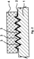
- Figures 1 , 2 and 3 show individual steps in the production of a final laminate comprising two layers 1, 5 of thermoplastic material with a diffractive optical element fixed between them.
- layer 2 whose index of refraction differs from that of layer 1 and/or layer 5 of thermoplastic material, is applied onto pre-selected areas of layer 1, as shown in Fig. 1 (for reasons of simplification, only one of these areas is shown in Fig. 1 ).
- this layer 2 is designated as "layer 2 with a different index of refraction”.
- Layer 2 with a different index of refraction is created by selective deposition of thin layers of material having a different index of refraction from that of thermoplastic laminate foils, such as metals (e.g. silver, aluminium, copper, chromium, gold, etc), metal alloys or non-metallic materials (e.g. ZnS, TiO 2 , etc).
- metals e.g. silver, aluminium, copper, chromium, gold, etc
- metal alloys or non-metallic materials e.g. ZnS, TiO 2 , etc.
- stamp 4 with optical diffractive relief 6 in corresponding areas to those of layer 2 with a different index of refraction is imprinted into the layer 2 with a different index of refraction and the carrying layer 1.
- stamp 4 With imprinting the stamp 4, its relief is transferred to the layer 2 with a different index of refraction (see Fig. 2 ), thus creating a diffractive optical element whose profile corresponds to that of the optical diffractive relief 6 on the lower side of the stamp 4.
- the carrying layer 1 with configured layer 2 having a different index of refraction is covered with a cover layer 5 of thermoplastic material and the resulting laminate is heated to 190°C, thus bonding the cover layer 5 of thermoplastic material with the carrying layer 1 of thermoplastic material.
- such a stamp 4 may be used whose optical diffractive relief 6 is, at least in some places, high enough to produce micro-fissures 3 (see Fig. 2 ) by imprinting the stamp 4 into the layer 2 with a different index of refraction. With the cover layer 5 in place and the entire laminate structure heated up, the micro-fissures 3 allow thermoplastic material to flow therethrough, thereby bonding the cover layer 5 with the carrying layer 1 (see Fig. 3 ).
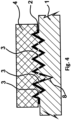
- such a stamp 4 may be used whose optical diffractive relief 6 has, at least in some places, recesses to produce perforations 8 in layer 2 with a different index of refraction, thus enabling easier bonding of thermoplastic material of the cover layer 5 with the material of the carrying layer 1 (see Fig. 4 ).
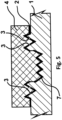
- such a stamp 4 may be used whose optical diffractive relief 6 is appropriately shaped so as to detach part 7 of the material of the layer 2 having a different index of refraction and with imprinted optical diffractive relief from the imprinted layer 2 with a different index of refraction at some places of the layer 2, and so as to press this part 7 of the material of layer 2 deeper into the carrying layer 1 than non-detached parts of the layer 2 with a different index of refraction (see Fig. 5 ). Owing to the different heights of the layer 2 with a different index of diffraction constituting the resulting optical diffractive relief, thermoplastic material of the cover layer 5 and the carrying layer 1 (see Fig. 6 ) flows therethrough during lamination.
- processing of layer 2 having a different index of refraction may be effected using one stamp 4 in one step or using several different stamps 4 in several steps.
- stamps and several steps allow, particularly, the making of perforations 8 in layer 2 with a different index of refraction, or detached parts thereof, as well as effecting the pressing of parts 7 of the material of layer 2 with a different index of refraction deeper into carrying layer 1 than non-detached parts thereof.
- FIG. 6 An example of the laminate produced according to the method as described above is shown in Fig. 6 .
- This laminate consists of at least two layers 1, 5 of thermoplastic materials with an intermediate layer 2 with a different index of refraction, which layer 2 creates a diffractive optical element.
- Layer 2 with a different index of refraction has micro-fissures 3, perforations 8 and a detached part 7 formed by imprinting using a shaped stamp 4 with optical diffractive relief 6.
- Micro-fissures 3, perforations 8 and detached part 7 allow thermoplastic material of layer 5 to flow therethrough, thereby bonding the thermoplastic materials of cover layer 5 and carrying layer 1 together.
- the manufacturing procedure for making a laminate in accordance with the invention, as well as the resulting laminate structure, can be used for the production of various identification cards with protective elements provided as diffractive optical elements, credit and debit cards, bank notes, polycarbonate data pages of passports, among other examples.
Landscapes
- Engineering & Computer Science (AREA)
- Physics & Mathematics (AREA)
- Manufacturing & Machinery (AREA)
- Mechanical Engineering (AREA)
- General Physics & Mathematics (AREA)
- Optics & Photonics (AREA)
- Health & Medical Sciences (AREA)
- Ophthalmology & Optometry (AREA)
- Laminated Bodies (AREA)
- Diffracting Gratings Or Hologram Optical Elements (AREA)
- Credit Cards Or The Like (AREA)
Applications Claiming Priority (1)
| Application Number | Priority Date | Filing Date | Title |
|---|---|---|---|
| PCT/CZ2014/000042 WO2015161834A1 (en) | 2014-04-23 | 2014-04-23 | Method of manufacturing laminate and the laminate |
Publications (2)
| Publication Number | Publication Date |
|---|---|
| EP3134249A1 EP3134249A1 (en) | 2017-03-01 |
| EP3134249B1 true EP3134249B1 (en) | 2025-06-04 |
Family
ID=50771021
Family Applications (1)
| Application Number | Title | Priority Date | Filing Date |
|---|---|---|---|
| EP14725351.2A Active EP3134249B1 (en) | 2014-04-23 | 2014-04-23 | Method of manufacturing laminate and the laminate |
Country Status (5)
| Country | Link |
|---|---|
| US (1) | US10105920B2 (pl) |
| EP (1) | EP3134249B1 (pl) |
| ES (1) | ES3040141T3 (pl) |
| PL (1) | PL3134249T3 (pl) |
| WO (1) | WO2015161834A1 (pl) |
Families Citing this family (1)
| Publication number | Priority date | Publication date | Assignee | Title |
|---|---|---|---|---|
| KR102388969B1 (ko) * | 2020-09-08 | 2022-04-21 | 엔비에스티(주) | 위변조 방지용 필름 및 이의 활용방법 |
Family Cites Families (10)
| Publication number | Priority date | Publication date | Assignee | Title |
|---|---|---|---|---|
| US3802101A (en) | 1972-02-03 | 1974-04-09 | Transaction Technology Inc | Coded identification card |
| DE2856833A1 (de) | 1978-12-30 | 1980-07-17 | Hoechst Ag | Identifikationskarte und verfahren zu ihrer herstellung |
| DE3248990T (de) * | 1981-08-24 | 1984-03-22 | Commonwealth Scientific And Industrial Research Organization, Campbell | Herstellung von geprägten Transferfolien und dergleichen |
| FR2638120B1 (fr) | 1988-10-24 | 1991-05-24 | Gaillon J Sa | Panneau composite et ses applications comme element de protection, de decoration et/ou d'identification |
| DE19813314A1 (de) * | 1998-03-26 | 1999-09-30 | Kurz Leonhard Fa | Prägefolie, insbesondere Heissprägefolie |
| WO2008060918A1 (en) | 2006-11-15 | 2008-05-22 | 3M Innovative Properties Company | Card with color-shifting film |
| GB0817865D0 (en) | 2008-10-01 | 2008-11-05 | Optaglio Sro | Embedded element and related method |
| GB0902000D0 (en) | 2009-02-09 | 2009-03-11 | Optaglio Sro | Micro-relief structures |
| DE102010034039A1 (de) * | 2010-08-11 | 2012-02-16 | Bundesdruckerei Gmbh | Verfahren zur Herstellung einer Folie für ein Sicherheits- und/oder Wertdokument |
| JP6237759B2 (ja) * | 2013-02-21 | 2017-11-29 | 凸版印刷株式会社 | 表示体およびラベル付き物品 |
-
2014
- 2014-04-23 PL PL14725351.2T patent/PL3134249T3/pl unknown
- 2014-04-23 WO PCT/CZ2014/000042 patent/WO2015161834A1/en not_active Ceased
- 2014-04-23 US US15/306,275 patent/US10105920B2/en active Active
- 2014-04-23 EP EP14725351.2A patent/EP3134249B1/en active Active
- 2014-04-23 ES ES14725351T patent/ES3040141T3/es active Active
Also Published As
| Publication number | Publication date |
|---|---|
| EP3134249A1 (en) | 2017-03-01 |
| ES3040141T3 (en) | 2025-10-28 |
| PL3134249T3 (pl) | 2026-02-16 |
| WO2015161834A1 (en) | 2015-10-29 |
| US20170043546A1 (en) | 2017-02-16 |
| US10105920B2 (en) | 2018-10-23 |
Similar Documents
| Publication | Publication Date | Title |
|---|---|---|
| JP5639075B2 (ja) | セキュリティエレメント及び転写フィルムの製造方法 | |
| RU2709924C1 (ru) | Способ изготовления защитного элемента, а также переносимой пленки | |
| KR100706077B1 (ko) | 적층체, 특히, 카드 형태로 된 적층체 및 상기 적층체를제작하는 방법 | |
| KR102465208B1 (ko) | 전사 필름 및 전사 필름 제조 방법 | |
| TWI842711B (zh) | 層合體和層壓薄膜的製造方法以及層合體和層壓薄膜 | |
| EP2605918B1 (de) | Dokument mit eingebettetem hologramm und verfahren zu dessen herstellung | |
| KR20180100344A (ko) | 보안 문서 몸체 내에 홀로그램을 집적하기 위한 방법 및 보안 문서 몸체 | |
| US12246524B2 (en) | Method for producing a film intermediate product, film intermediate product and method for producing a product | |
| EP3134249B1 (en) | Method of manufacturing laminate and the laminate | |
| EP2532509A2 (en) | Optically variable device (ovd) images embedded within plastic strips | |
| US20250273095A1 (en) | Laminate and method for producing a laminate | |
| DE102011011051B3 (de) | Verfahren zur Herstellung eines Laminats sowie Kartenkörper aus diesem | |
| KR20190039098A (ko) | 적어도 하나의 회절요소를 구비하는 폴리머 라미네이트 및 그것을 제조하기 위한 방법 | |
| JP6451328B2 (ja) | 転写箔、画像保持体、冊子、および、カード | |
| EP3045307B1 (en) | Laminated credential |
Legal Events
| Date | Code | Title | Description |
|---|---|---|---|
| STAA | Information on the status of an ep patent application or granted ep patent |
Free format text: STATUS: THE INTERNATIONAL PUBLICATION HAS BEEN MADE |
|
| PUAI | Public reference made under article 153(3) epc to a published international application that has entered the european phase |
Free format text: ORIGINAL CODE: 0009012 |
|
| STAA | Information on the status of an ep patent application or granted ep patent |
Free format text: STATUS: REQUEST FOR EXAMINATION WAS MADE |
|
| 17P | Request for examination filed |
Effective date: 20161121 |
|
| AK | Designated contracting states |
Kind code of ref document: A1 Designated state(s): AL AT BE BG CH CY CZ DE DK EE ES FI FR GB GR HR HU IE IS IT LI LT LU LV MC MK MT NL NO PL PT RO RS SE SI SK SM TR |
|
| AX | Request for extension of the european patent |
Extension state: BA ME |
|
| DAX | Request for extension of the european patent (deleted) | ||
| STAA | Information on the status of an ep patent application or granted ep patent |
Free format text: STATUS: EXAMINATION IS IN PROGRESS |
|
| 17Q | First examination report despatched |
Effective date: 20190215 |
|
| GRAP | Despatch of communication of intention to grant a patent |
Free format text: ORIGINAL CODE: EPIDOSNIGR1 |
|
| STAA | Information on the status of an ep patent application or granted ep patent |
Free format text: STATUS: GRANT OF PATENT IS INTENDED |
|
| INTG | Intention to grant announced |
Effective date: 20241219 |
|
| GRAS | Grant fee paid |
Free format text: ORIGINAL CODE: EPIDOSNIGR3 |
|
| GRAA | (expected) grant |
Free format text: ORIGINAL CODE: 0009210 |
|
| STAA | Information on the status of an ep patent application or granted ep patent |
Free format text: STATUS: THE PATENT HAS BEEN GRANTED |
|
| RAP3 | Party data changed (applicant data changed or rights of an application transferred) |
Owner name: IQS GROUP S.R.O. |
|
| RAP3 | Party data changed (applicant data changed or rights of an application transferred) |
Owner name: IQS GROUP A.S. |
|
| AK | Designated contracting states |
Kind code of ref document: B1 Designated state(s): AL AT BE BG CH CY CZ DE DK EE ES FI FR GB GR HR HU IE IS IT LI LT LU LV MC MK MT NL NO PL PT RO RS SE SI SK SM TR |
|
| REG | Reference to a national code |
Ref country code: GB Ref legal event code: FG4D |
|
| REG | Reference to a national code |
Ref country code: CH Ref legal event code: EP |
|
| REG | Reference to a national code |
Ref country code: DE Ref legal event code: R096 Ref document number: 602014092002 Country of ref document: DE |
|
| REG | Reference to a national code |
Ref country code: IE Ref legal event code: FG4D |
|
| REG | Reference to a national code |
Ref country code: NL Ref legal event code: FP |
|
| PG25 | Lapsed in a contracting state [announced via postgrant information from national office to epo] |
Ref country code: FI Free format text: LAPSE BECAUSE OF FAILURE TO SUBMIT A TRANSLATION OF THE DESCRIPTION OR TO PAY THE FEE WITHIN THE PRESCRIBED TIME-LIMIT Effective date: 20250604 |
|
| REG | Reference to a national code |
Ref country code: LT Ref legal event code: MG9D |
|
| PG25 | Lapsed in a contracting state [announced via postgrant information from national office to epo] |
Ref country code: NO Free format text: LAPSE BECAUSE OF FAILURE TO SUBMIT A TRANSLATION OF THE DESCRIPTION OR TO PAY THE FEE WITHIN THE PRESCRIBED TIME-LIMIT Effective date: 20250904 |
|
| PG25 | Lapsed in a contracting state [announced via postgrant information from national office to epo] |
Ref country code: HR Free format text: LAPSE BECAUSE OF FAILURE TO SUBMIT A TRANSLATION OF THE DESCRIPTION OR TO PAY THE FEE WITHIN THE PRESCRIBED TIME-LIMIT Effective date: 20250604 |
|
| PG25 | Lapsed in a contracting state [announced via postgrant information from national office to epo] |
Ref country code: RS Free format text: LAPSE BECAUSE OF FAILURE TO SUBMIT A TRANSLATION OF THE DESCRIPTION OR TO PAY THE FEE WITHIN THE PRESCRIBED TIME-LIMIT Effective date: 20250904 |
|
| REG | Reference to a national code |
Ref country code: ES Ref legal event code: FG2A Ref document number: 3040141 Country of ref document: ES Kind code of ref document: T3 Effective date: 20251028 |
|
| PG25 | Lapsed in a contracting state [announced via postgrant information from national office to epo] |
Ref country code: LV Free format text: LAPSE BECAUSE OF FAILURE TO SUBMIT A TRANSLATION OF THE DESCRIPTION OR TO PAY THE FEE WITHIN THE PRESCRIBED TIME-LIMIT Effective date: 20250604 |
|
| REG | Reference to a national code |
Ref country code: GR Ref legal event code: EP Ref document number: 20250401746 Country of ref document: GR Effective date: 20251009 |
|
| PG25 | Lapsed in a contracting state [announced via postgrant information from national office to epo] |
Ref country code: PT Free format text: LAPSE BECAUSE OF FAILURE TO SUBMIT A TRANSLATION OF THE DESCRIPTION OR TO PAY THE FEE WITHIN THE PRESCRIBED TIME-LIMIT Effective date: 20251006 |
|
| REG | Reference to a national code |
Ref country code: AT Ref legal event code: MK05 Ref document number: 1799951 Country of ref document: AT Kind code of ref document: T Effective date: 20250604 |
|
| PG25 | Lapsed in a contracting state [announced via postgrant information from national office to epo] |
Ref country code: IS Free format text: LAPSE BECAUSE OF FAILURE TO SUBMIT A TRANSLATION OF THE DESCRIPTION OR TO PAY THE FEE WITHIN THE PRESCRIBED TIME-LIMIT Effective date: 20251004 |
|
| PG25 | Lapsed in a contracting state [announced via postgrant information from national office to epo] |
Ref country code: SM Free format text: LAPSE BECAUSE OF FAILURE TO SUBMIT A TRANSLATION OF THE DESCRIPTION OR TO PAY THE FEE WITHIN THE PRESCRIBED TIME-LIMIT Effective date: 20250604 Ref country code: AT Free format text: LAPSE BECAUSE OF FAILURE TO SUBMIT A TRANSLATION OF THE DESCRIPTION OR TO PAY THE FEE WITHIN THE PRESCRIBED TIME-LIMIT Effective date: 20250604 |
|
| PG25 | Lapsed in a contracting state [announced via postgrant information from national office to epo] |
Ref country code: EE Free format text: LAPSE BECAUSE OF FAILURE TO SUBMIT A TRANSLATION OF THE DESCRIPTION OR TO PAY THE FEE WITHIN THE PRESCRIBED TIME-LIMIT Effective date: 20250604 |
|
| PG25 | Lapsed in a contracting state [announced via postgrant information from national office to epo] |
Ref country code: RO Free format text: LAPSE BECAUSE OF FAILURE TO SUBMIT A TRANSLATION OF THE DESCRIPTION OR TO PAY THE FEE WITHIN THE PRESCRIBED TIME-LIMIT Effective date: 20250604 Ref country code: SK Free format text: LAPSE BECAUSE OF FAILURE TO SUBMIT A TRANSLATION OF THE DESCRIPTION OR TO PAY THE FEE WITHIN THE PRESCRIBED TIME-LIMIT Effective date: 20250604 |