EP3134229B1 - Manual machine tool - Google Patents
Manual machine tool Download PDFInfo
- Publication number
- EP3134229B1 EP3134229B1 EP15714205.0A EP15714205A EP3134229B1 EP 3134229 B1 EP3134229 B1 EP 3134229B1 EP 15714205 A EP15714205 A EP 15714205A EP 3134229 B1 EP3134229 B1 EP 3134229B1
- Authority
- EP
- European Patent Office
- Prior art keywords
- sectors
- machine tool
- disc
- tool
- hand machine
- Prior art date
- Legal status (The legal status is an assumption and is not a legal conclusion. Google has not performed a legal analysis and makes no representation as to the accuracy of the status listed.)
- Active
Links
Images


Classifications
-
- B—PERFORMING OPERATIONS; TRANSPORTING
- B25—HAND TOOLS; PORTABLE POWER-DRIVEN TOOLS; MANIPULATORS
- B25D—PERCUSSIVE TOOLS
- B25D16/00—Portable percussive machines with superimposed rotation, the rotational movement of the output shaft of a motor being modified to generate axial impacts on the tool bit
- B25D16/003—Clutches specially adapted therefor
-
- F—MECHANICAL ENGINEERING; LIGHTING; HEATING; WEAPONS; BLASTING
- F16—ENGINEERING ELEMENTS AND UNITS; GENERAL MEASURES FOR PRODUCING AND MAINTAINING EFFECTIVE FUNCTIONING OF MACHINES OR INSTALLATIONS; THERMAL INSULATION IN GENERAL
- F16D—COUPLINGS FOR TRANSMITTING ROTATION; CLUTCHES; BRAKES
- F16D7/00—Slip couplings, e.g. slipping on overload, for absorbing shock
- F16D7/02—Slip couplings, e.g. slipping on overload, for absorbing shock of the friction type
- F16D7/024—Slip couplings, e.g. slipping on overload, for absorbing shock of the friction type with axially applied torque limiting friction surfaces
- F16D7/025—Slip couplings, e.g. slipping on overload, for absorbing shock of the friction type with axially applied torque limiting friction surfaces with flat clutching surfaces, e.g. discs
-
- B—PERFORMING OPERATIONS; TRANSPORTING
- B25—HAND TOOLS; PORTABLE POWER-DRIVEN TOOLS; MANIPULATORS
- B25D—PERCUSSIVE TOOLS
- B25D2250/00—General details of portable percussive tools; Components used in portable percussive tools
- B25D2250/165—Overload clutches, torque limiters
Definitions
- the present invention relates to a hand tool machine for rotating tools, in particular a drill or a hammer drill.
- a generic hand tool with the features of the preamble of claim 1 is known from DE 29 51 420 A1 known.
- An exemplary hammer drill is from the US5954457A known.
- the hammer drill has a pneumatic percussion mechanism, which is based on a motor piston moved back and forth by means of a motor and a percussion piston coupled to the exciter piston via an air spring.
- a drill can be rotated about its axis in addition to the strokes by means of a rotary drive.
- An overload clutch separates the rotary actuator from the engine.
- the overload clutch is integrated in a hollow pinion.
- a motor-side shaft is provided with spring-loaded locking elements, which engage in a form-fitting manner in the radial direction in the pinion.
- the hand tool according to the invention according to claim 1 has a tool holder for receiving a tool on a working axis, a motor and a pneumatic percussion.
- An output shaft is coupled to the tool holder for rotating the tool about the working axis.
- a slip clutch is disposed in the drive train between the engine and the output shaft.
- the slip clutch has a drive-side disc and a driven-side disc.
- the drive-side disk has first sectors with a high coefficient of friction and second sectors with a low coefficient of friction on a driving annular surface adjacent to the driven-side disk.
- the driven-side disk has third sectors with a high coefficient of friction and fourth sectors with a low coefficient of friction on the driven annular surface bearing against the driving annular surface.
- the first sectors and the third sectors have a rubberized surface and the second sectors and the fourth sectors have a polished steel surface.
- the slip clutch allows a very compact design with a small number of individual components, which simplifies assembly.
- Fig. 1 schematically shows a hammer drill 1 as an example of a chiseling hand tool .
- the hammer drill 1 has a tool holder 2, in which a shank end 3 of a tool, for example one of the drill 4, can be used.
- a primary drive of the hammer drill 1 is a motor 5, which drives a striking mechanism 6 and an output shaft 7 .
- a battery pack 8 or a power line supplies the motor 5 with power.
- a user can guide the hammer drill 1 by means of a handle 9 and be by means of a system switch 10 to the hammer drill 1 is in operation.
- the hammer drill 1 rotates the drill 4 continuously about a working axis 11 and can beat the drill 4 in the direction of impact 12 along the working axis 11 in a substrate.
- the percussion 6 is a pneumatic percussion 6.
- An exciter piston 13 and a racket 14 are movably guided in a guide tube 15 in the striking mechanism 6 along the working axis 11 .
- the excitation piston 13 is coupled via an eccentric 16 to the motor 5 and forced to a periodic, linear movement.
- a connecting rod 17 connects the eccentric 16 with the exciter piston 13.
- An air spring formed by a pneumatic chamber 18 between the excitation piston 13 and the racket 14 couples a movement of the racket 14 to the movement of the exciter piston 13 .
- the racket 14 can strike directly on a rear end of the drill 4 or indirectly transmit a portion of its pulse to the drill 4 via a substantially resting intermediate racket 19 .
- the striking mechanism 6 and preferably the further drive components are arranged within a machine housing 20 .
- the output shaft 7 is preferably a hollow tube, which merges into the guide tube 15 .
- a bevel gear 21 is arranged coaxially on the output shaft 7 .
- the bevel gear 21 may be non-rotatably connected to the output shaft 7 by means of a press fit or by means of a toothing.
- a pinion 22 meshes with the bevel gear 21.
- the pinion 22 rotates about an axis of rotation 23.
- a slip clutch 24 is arranged, which interrupts a transmission of torque during an overload briefly.
- the slip clutch 24 has a drive-side disk 25 and a driven-side disk 26, which rotate by way of example about the same axis of rotation as the pinion 22 .
- the drive-side disk 25 is, for example, a gear with a spur toothing, which meshes with a gear wheel on the motor shaft.
- a sleeve 27 decouples the drive-side disk 25 from the pinion 22.
- the output-side disk 26 is rotatably connected to the pinion 22 .
- the drive-side disk 25 has an active side with an annular surface 28.
- the driven-side disk 26 also has an active side with an annular surface 29. The two active sides touch each other, in particular the two annular surfaces 28, 29.
- a spring 30 turns that the both annular surfaces 28, 29 are permanently in contact.
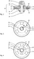
- the annular surface 28 of the drive-side disk 25 is in Fig. 3 shown in a plan view.
- the annular surface 28 has an inner radius 31 and an outer radius 32.
- the exemplary annular surface 28 has three first sectors 33 which are provided with a rubber coating.
- the first sectors 33 preferably each cover an angle of less than 45 degrees viewed from the axis of rotation 23 .
- the three first sectors 33 are distributed symmetrically about the axis of rotation 23 .
- the remaining other three second sectors 34 are polished steel surfaces.
- the annular surface 29 of the driven-side disk 26 is preferably formed equal to the annular surface 33 of the drive-side disk 25 .
- the driven-side annular surface 29 also has three (third) sectors 35 which are rubberized. Their dimensions are preferably equal to the first sectors 33.
- the remaining (fourth) sectors 36 are polished steel surfaces.
- the slip clutch 24 remains in engagement as long as the rubberized first and third sectors 33, 35 lie on each other.
- the contact pressure of the spring 30 increases the adhesion of the two sectors 33 , 35.
- the driving pulley 25 slips and the first sectors 33 increasingly and finally overlap exclusively with the fourth sectors 36.
- the driving pulley 25 can now be rotated with almost no torque against the abortive disk 26 . Accordingly, the motor 5 accelerates .
- the large angle of preferably more than 75 degrees between the first sectors 33 allows a long acceleration phase.
- the motor 5 can generate a high torque peak, for example, to release a drill 4 , which can not turn at a lower static torque and the slip clutch 24 triggers.
- the annular surfaces 28, 29 have three, two or preferably only a first w. third sector 33, 35.
- the sectors 33, 35 occupy between 25% and 40% of the annular surface 29 in order to provide sufficient adhesion for the transmission of torque.
- Fig. 4 shows a further embodiment in which the driving pulley 25 has two concentric annular surfaces 28, 37 . The two annular surfaces 28, 37 do not overlap.
- Both annular surfaces 28, 37 have first sectors 33, 38 with a rubber coating and second sectors 34, 39 with a polished steel surface.
- the first sectors 33 of the outer annular surface 28 are preferably offset from the sectors 38 of the inner annular surface 37 by half the angle between the first sectors 33 of the outer annular surface 28 .
- Fig. 5 and Fig. 6 show a further embodiment in which the second sectors 34 include one or more to the axis 23 concentric circular webs 40 .
- the roof surfaces of the webs 40 lie in a plane with the annular surface 28. Between the webs 40 is a corresponding concentric groove.
- the first sectors 33 touch completely and the second sectors touch only by means of the webs 40, the annular surface 29 of the driven pulley 26.
- the driven pulley 26 may be formed identical to the driving pulley 25 .
Landscapes
- Engineering & Computer Science (AREA)
- General Engineering & Computer Science (AREA)
- Mechanical Engineering (AREA)
- Percussive Tools And Related Accessories (AREA)
Description
Die vorliegende Erfindung betrifft eine Handwerkzeugmaschine für rotierende Werkzeuge, insbesondere eine Bohrmaschine oder einen Bohrhammer. Eine gattungsgemäße Handwerkzeugmaschine mit den Merkmalen des Oberbegriffs von Anspruch 1 ist aus der
Ein beispielhafter Bohrhammer ist aus der
Die erfindungsgemäße Handwerkzeugmaschine gemäß Anspruch 1 hat eine Werkzeugaufnahme zum Aufnehmen eines Werkzeugs auf einer Arbeitsachse, einen Motor und ein pneumatisches Schlagwerk. Eine Abtriebswelle ist mit der Werkzeugaufnahme zum Drehen des Werkzeugs um die Arbeitsachse gekoppelt. Eine Rutschkupplung ist in dem Antriebsstrang zwischen dem Motor und der Abtriebswelle angeordnet. Die Rutschkupplung hat eine antriebsseitige Scheibe und eine abtriebsseitige Scheibe. Die antriebsseitige Scheibe hat auf einer an der abtriebsseitigen Scheibe anliegenden, antreibenden Ringfläche erste Sektoren mit einem hohen Reibwert und zweite Sektoren mit einem geringen Reibwert. Die abtriebsseitige Scheibe hat auf der an der antreibenden Ringfläche anliegenden, angetriebenen Ringfläche dritte Sektoren mit einem hohen Reibwert und vierte Sektoren mit einem geringen Reibwert. Die ersten Sektoren und die dritten Sektoren weisen eine gummierte Oberfläche und die zweiten Sektoren und die vierten Sektoren eine polierte Stahlfläche auf.The hand tool according to the invention according to claim 1 has a tool holder for receiving a tool on a working axis, a motor and a pneumatic percussion. An output shaft is coupled to the tool holder for rotating the tool about the working axis. A slip clutch is disposed in the drive train between the engine and the output shaft. The slip clutch has a drive-side disc and a driven-side disc. The drive-side disk has first sectors with a high coefficient of friction and second sectors with a low coefficient of friction on a driving annular surface adjacent to the driven-side disk. The driven-side disk has third sectors with a high coefficient of friction and fourth sectors with a low coefficient of friction on the driven annular surface bearing against the driving annular surface. The first sectors and the third sectors have a rubberized surface and the second sectors and the fourth sectors have a polished steel surface.
Die Rutschkupplung ermöglicht einen sehr kompakten Aufbau mit einer geringen Anzahl von einzelnen Bauelementen, was die Montage vereinfacht.The slip clutch allows a very compact design with a small number of individual components, which simplifies assembly.
Die nachfolgende Beschreibung erläutert die Erfindung anhand von exemplarischen Ausführungsformen und Figuren. In den Figuren zeigen:
- Fig. 1
- einen Bohrhammer
- Fig. 2
- eine Rutschkupplung,
- Fig. 3
- eine Scheibe der Rutschkupplung in Draufsicht
- Fig. 4
- eine Scheibe einer Rutschkupplung in Draufsicht
- Fig. 5
- eine Rutschkupplung
- Fig. 6
- eine Scheibe der Rutschkupplung in Draufsicht
- Fig. 1
- a hammer drill
- Fig. 2
- a slip clutch,
- Fig. 3
- a disc of the friction clutch in plan view
- Fig. 4
- a disc of a friction clutch in plan view
- Fig. 5
- a slip clutch
- Fig. 6
- a disc of the friction clutch in plan view
Gleiche oder funktionsgleiche Elemente werden durch gleiche Bezugszeichen in den Figuren indiziert, soweit nicht anders angegeben.Identical or functionally identical elements are indicated by the same reference numerals in the figures, unless stated otherwise.
Das Schlagwerk 6 ist ein pneumatisches Schlagwerk 6. Ein Erregerkolben 13 und ein Schläger 14 sind in einem Führungsrohr 15 in dem Schlagwerk 6 längs der Arbeitsachse 11 beweglich geführt. Der Erregerkolben 13 ist über einen Exzenter 16 an den Motor 5 angekoppelt und zu einer periodischen, linearen Bewegung gezwungen. Ein Pleuel 17 verbindet den Exzenter 16 mit dem Erregerkolben 13. Eine Luftfeder gebildet durch eine pneumatische Kammer 18 zwischen dem Erregerkolben 13 und dem Schläger 14 koppelt eine Bewegung des Schlägers 14 an die Bewegung des Erregerkolbens 13 an. Der Schläger 14 kann direkt auf ein hinteres Ende des Bohrers 4 aufschlagen oder mittelbar über einen im Wesentlichen ruhenden Zwischenschläger 19 einen Teil seines Impuls auf den Bohrer 4 übertragen. Das Schlagwerk 6 und vorzugsweise die weiteren Antriebskomponenten sind innerhalb eines Maschinengehäuses 20 angeordnet.
Die Abtriebswelle 7 ist vorzugsweise ein hohles Rohr, welches in das Führungsrohr 15 übergeht. Ein Kegelrad 21 ist koaxial auf der Abtriebswelle 7 angeordnet. Das Kegelrad 21 kann mittels eines Presssitzes oder mittels einer Verzahnung drehfest mit der Abtriebswelle 7 verbunden sein. Ein Ritzel 22 kämmt mit dem Kegelrad 21. Das Ritzel 22 dreht um eine Drehachse 23. Zwischen dem Ritzel 22 und dem Motor 5 ist eine Rutschkupplung 24 angeordnet, welche eine Übertragung eines Drehmoments bei einer Überlast kurzzeitig unterbricht. Die Rutschkupplung 24 hat eine antriebsseitige Scheibe 25 und eine abtriebsseitige Scheibe 26, welche beispielhaft um die gleiche Drehachse wie das Ritzel 22 drehen. Die antriebsseitige Scheibe 25 ist beispielsweise ein Zahnrad mit einer Stirnverzahnung, die mit einem Zahnrad auf der Motorwelle kämmt. Eine Hülse 27 entkoppelt die antriebsseitige Scheibe 25 von dem Ritzel 22. Die abtriebsseitige Scheibe 26 ist drehfest mit dem Ritzel 22 verbunden.
Die antriebseitige Scheibe 25 hat eine aktive Seite mit einer Ringfläche 28. Die abtriebsseitige Scheibe 26 hat ebenfalls eine aktive Seite mit einer Ringfläche 29. Die beiden aktiven Seiten berühren einander, insbesondere die beiden Ringflächen 28, 29. Eine Feder 30 stellt sich, dass die beiden Ringflächen 28, 29 permanent in Kontakt sind. Vorzugsweise ist weder die antriebsseitige Scheibe 25 noch die abtriebsseitige Scheibe 26 längs der Drehachse 23 beweglich.
Die Ringfläche 28 der antriebsseitigen Scheibe 25 ist in
Bei einer bevorzugten Ausgestaltung haben die Ringflächen 28, 29 drei, zwei oder vorzugsweise nur einen ersten w. dritten Sektor 33, 35. Die Sektoren 33, 35 nehmen zwischen 25 % und 40 % der Ringfläche 29 ein, um eine ausreichende Haftung für die Übertragung eines Drehmoments bereitzustellen.
The
The drive-
The
In a preferred embodiment, the
Claims (5)
- Hand machine tool (1) with
a tool holder (2) for holding a tool (4) on a working axis (11),
a motor (5),
a pneumatic striking mechanism (6),
an output shaft (7), which is connected to the tool holder (2) for turning the tool around the working axis (11), and
a slip clutch (24), which is arranged in the drive train between the motor (5) and the output shaft (7),
in which the slip clutch (24) has a disc (25) on the drive side and a disc (26) on the output side, characterised in that the disc (25) on the drive side has first sectors (33) with a high friction value and second sectors (34) with a low friction value on a driving ring face (28) adjoining the disc (26) on the output side and the disc (26) on the output side has third sectors (35) with a high friction value and fourth sectors (36) with a low friction value on the driven ring face (29) adjoining the driving ring face (28) and the first sectors (33) and the third sectors (35) have a rubberised surface and the second sectors (34) and the fourth sectors (36) have a polished steel surface. - Hand machine tool (1) according to claim 1, characterised in that a spring (30) holds both ring faces (28, 29) in permanent contact.
- Hand machine tool (1) according to one of the previous claims, characterised in that the ring faces (28, 29) have a maximum of three first sectors (33) and a maximum of three third sectors (35).
- Hand machine tool (1) according to claim 3, characterised in that the first sectors (33) and the third sectors (35) cover a quarter to a third of the ring faces (28, 29).
- Hand machine tool (1) according to one of the previous claims, characterised in that the second sectors (34) have studs (40) that are concentric to the working axis (11), which lie on a level with the first sector (33).
Applications Claiming Priority (2)
| Application Number | Priority Date | Filing Date | Title |
|---|---|---|---|
| EP14165357.6A EP2937186A1 (en) | 2014-04-22 | 2014-04-22 | Manual machine tool |
| PCT/EP2015/057158 WO2015161994A1 (en) | 2014-04-22 | 2015-04-01 | Portable power tool |
Publications (2)
| Publication Number | Publication Date |
|---|---|
| EP3134229A1 EP3134229A1 (en) | 2017-03-01 |
| EP3134229B1 true EP3134229B1 (en) | 2018-10-24 |
Family
ID=50513759
Family Applications (2)
| Application Number | Title | Priority Date | Filing Date |
|---|---|---|---|
| EP14165357.6A Withdrawn EP2937186A1 (en) | 2014-04-22 | 2014-04-22 | Manual machine tool |
| EP15714205.0A Active EP3134229B1 (en) | 2014-04-22 | 2015-04-01 | Manual machine tool |
Family Applications Before (1)
| Application Number | Title | Priority Date | Filing Date |
|---|---|---|---|
| EP14165357.6A Withdrawn EP2937186A1 (en) | 2014-04-22 | 2014-04-22 | Manual machine tool |
Country Status (3)
| Country | Link |
|---|---|
| US (1) | US20170043465A1 (en) |
| EP (2) | EP2937186A1 (en) |
| WO (1) | WO2015161994A1 (en) |
Families Citing this family (1)
| Publication number | Priority date | Publication date | Assignee | Title |
|---|---|---|---|---|
| US11826891B2 (en) * | 2019-10-21 | 2023-11-28 | Makita Corporation | Power tool having hammer mechanism |
Family Cites Families (4)
| Publication number | Priority date | Publication date | Assignee | Title |
|---|---|---|---|---|
| SU947416A1 (en) * | 1978-12-27 | 1982-07-30 | Всесоюзный Научно-Исследовательский И Проектно-Конструкторский Институт Механизированного И Ручного Строительно-Монтажного Инструмента,Вибраторов И Строительно-Отделочных Машин | Rotary-percussive machine |
| JPS5969529A (en) * | 1982-10-13 | 1984-04-19 | Fuji Xerox Co Ltd | Dry type slip clutch |
| DE3942806A1 (en) * | 1989-12-23 | 1991-06-27 | Metabowerke Kg | Torque limiter for electric tool - with friction surfaces having recesses for lubricant and swarf |
| DE19646381A1 (en) | 1996-11-11 | 1998-05-14 | Hilti Ag | Handheld device |
-
2014
- 2014-04-22 EP EP14165357.6A patent/EP2937186A1/en not_active Withdrawn
-
2015
- 2015-04-01 EP EP15714205.0A patent/EP3134229B1/en active Active
- 2015-04-01 US US15/305,978 patent/US20170043465A1/en not_active Abandoned
- 2015-04-01 WO PCT/EP2015/057158 patent/WO2015161994A1/en active Application Filing
Non-Patent Citations (1)
| Title |
|---|
| None * |
Also Published As
| Publication number | Publication date |
|---|---|
| EP2937186A1 (en) | 2015-10-28 |
| WO2015161994A1 (en) | 2015-10-29 |
| EP3134229A1 (en) | 2017-03-01 |
| US20170043465A1 (en) | 2017-02-16 |
Similar Documents
| Publication | Publication Date | Title |
|---|---|---|
| EP2379281B1 (en) | Hand-held machine tool | |
| DE102008022454B4 (en) | Rotary Hammer | |
| DE2242944B2 (en) | Hammer drill | |
| DE102011084499A1 (en) | tool attachment | |
| DE2252951B2 (en) | Hammer drill | |
| DE202008001449U1 (en) | Switching device for impact tool | |
| DE102012209874A1 (en) | transmission device | |
| EP3250344A1 (en) | Percussion mechanism device, in particular for an impact wrench | |
| DE2147383C2 (en) | Impact wrench, especially for rail fastening screws | |
| EP2612731B1 (en) | Handheld tool apparatus | |
| EP2134512B1 (en) | Gearbox device | |
| EP2561962B1 (en) | Hand-held tool machine | |
| EP2700477B1 (en) | Drive train assembly for a machine tool and machine tool | |
| EP3134229B1 (en) | Manual machine tool | |
| DE102007062248A1 (en) | Hand tool with a, at least one rotatably mounted intermediate shaft comprehensive gear device | |
| EP3053708B1 (en) | Accessory device | |
| EP2347865A1 (en) | Electrical tool | |
| WO2009092366A2 (en) | Hammer mechanism for a power tool, particularly for a hand power tool such as an electric hammer drill or an impact wrench | |
| DE102014101827A1 (en) | Drilling machine and drilling tool for this | |
| EP3493951A1 (en) | Attachment device | |
| EP3782766A1 (en) | Handheld machine tool | |
| EP2522466B1 (en) | Hand-held power tool and operating method of a hand-held power tool | |
| EP2104594B1 (en) | Hand held power tool | |
| DE202007001274U1 (en) | Percussive tool for e.g. boring, has motor with drive gear shaft and impact hub with multiple hammer blocks, where polygonal shaft corresponds to transmission shaft and the multiple projections, on which hammer blocks hit | |
| WO2006056513A1 (en) | Hand machine tool with operation mode switching |
Legal Events
| Date | Code | Title | Description |
|---|---|---|---|
| STAA | Information on the status of an ep patent application or granted ep patent |
Free format text: STATUS: THE INTERNATIONAL PUBLICATION HAS BEEN MADE |
|
| PUAI | Public reference made under article 153(3) epc to a published international application that has entered the european phase |
Free format text: ORIGINAL CODE: 0009012 |
|
| STAA | Information on the status of an ep patent application or granted ep patent |
Free format text: STATUS: REQUEST FOR EXAMINATION WAS MADE |
|
| 17P | Request for examination filed |
Effective date: 20161122 |
|
| AK | Designated contracting states |
Kind code of ref document: A1 Designated state(s): AL AT BE BG CH CY CZ DE DK EE ES FI FR GB GR HR HU IE IS IT LI LT LU LV MC MK MT NL NO PL PT RO RS SE SI SK SM TR |
|
| AX | Request for extension of the european patent |
Extension state: BA ME |
|
| DAV | Request for validation of the european patent (deleted) | ||
| DAX | Request for extension of the european patent (deleted) | ||
| GRAP | Despatch of communication of intention to grant a patent |
Free format text: ORIGINAL CODE: EPIDOSNIGR1 |
|
| STAA | Information on the status of an ep patent application or granted ep patent |
Free format text: STATUS: GRANT OF PATENT IS INTENDED |
|
| RIC1 | Information provided on ipc code assigned before grant |
Ipc: F16D 7/02 20060101ALI20180627BHEP Ipc: B25D 16/00 20060101AFI20180627BHEP |
|
| INTG | Intention to grant announced |
Effective date: 20180726 |
|
| GRAS | Grant fee paid |
Free format text: ORIGINAL CODE: EPIDOSNIGR3 |
|
| GRAA | (expected) grant |
Free format text: ORIGINAL CODE: 0009210 |
|
| STAA | Information on the status of an ep patent application or granted ep patent |
Free format text: STATUS: THE PATENT HAS BEEN GRANTED |
|
| AK | Designated contracting states |
Kind code of ref document: B1 Designated state(s): AL AT BE BG CH CY CZ DE DK EE ES FI FR GB GR HR HU IE IS IT LI LT LU LV MC MK MT NL NO PL PT RO RS SE SI SK SM TR |
|
| REG | Reference to a national code |
Ref country code: CH Ref legal event code: EP |
|
| REG | Reference to a national code |
Ref country code: IE Ref legal event code: FG4D Free format text: LANGUAGE OF EP DOCUMENT: GERMAN |
|
| REG | Reference to a national code |
Ref country code: AT Ref legal event code: REF Ref document number: 1056121 Country of ref document: AT Kind code of ref document: T Effective date: 20181115 |
|
| REG | Reference to a national code |
Ref country code: DE Ref legal event code: R096 Ref document number: 502015006570 Country of ref document: DE |
|
| REG | Reference to a national code |
Ref country code: NL Ref legal event code: MP Effective date: 20181024 |
|
| REG | Reference to a national code |
Ref country code: LT Ref legal event code: MG4D |
|
| PG25 | Lapsed in a contracting state [announced via postgrant information from national office to epo] |
Ref country code: NL Free format text: LAPSE BECAUSE OF FAILURE TO SUBMIT A TRANSLATION OF THE DESCRIPTION OR TO PAY THE FEE WITHIN THE PRESCRIBED TIME-LIMIT Effective date: 20181024 |
|
| PG25 | Lapsed in a contracting state [announced via postgrant information from national office to epo] |
Ref country code: LV Free format text: LAPSE BECAUSE OF FAILURE TO SUBMIT A TRANSLATION OF THE DESCRIPTION OR TO PAY THE FEE WITHIN THE PRESCRIBED TIME-LIMIT Effective date: 20181024 Ref country code: PL Free format text: LAPSE BECAUSE OF FAILURE TO SUBMIT A TRANSLATION OF THE DESCRIPTION OR TO PAY THE FEE WITHIN THE PRESCRIBED TIME-LIMIT Effective date: 20181024 Ref country code: HR Free format text: LAPSE BECAUSE OF FAILURE TO SUBMIT A TRANSLATION OF THE DESCRIPTION OR TO PAY THE FEE WITHIN THE PRESCRIBED TIME-LIMIT Effective date: 20181024 Ref country code: FI Free format text: LAPSE BECAUSE OF FAILURE TO SUBMIT A TRANSLATION OF THE DESCRIPTION OR TO PAY THE FEE WITHIN THE PRESCRIBED TIME-LIMIT Effective date: 20181024 Ref country code: NO Free format text: LAPSE BECAUSE OF FAILURE TO SUBMIT A TRANSLATION OF THE DESCRIPTION OR TO PAY THE FEE WITHIN THE PRESCRIBED TIME-LIMIT Effective date: 20190124 Ref country code: IS Free format text: LAPSE BECAUSE OF FAILURE TO SUBMIT A TRANSLATION OF THE DESCRIPTION OR TO PAY THE FEE WITHIN THE PRESCRIBED TIME-LIMIT Effective date: 20190224 Ref country code: BG Free format text: LAPSE BECAUSE OF FAILURE TO SUBMIT A TRANSLATION OF THE DESCRIPTION OR TO PAY THE FEE WITHIN THE PRESCRIBED TIME-LIMIT Effective date: 20190124 Ref country code: ES Free format text: LAPSE BECAUSE OF FAILURE TO SUBMIT A TRANSLATION OF THE DESCRIPTION OR TO PAY THE FEE WITHIN THE PRESCRIBED TIME-LIMIT Effective date: 20181024 Ref country code: LT Free format text: LAPSE BECAUSE OF FAILURE TO SUBMIT A TRANSLATION OF THE DESCRIPTION OR TO PAY THE FEE WITHIN THE PRESCRIBED TIME-LIMIT Effective date: 20181024 |
|
| PG25 | Lapsed in a contracting state [announced via postgrant information from national office to epo] |
Ref country code: GR Free format text: LAPSE BECAUSE OF FAILURE TO SUBMIT A TRANSLATION OF THE DESCRIPTION OR TO PAY THE FEE WITHIN THE PRESCRIBED TIME-LIMIT Effective date: 20190125 Ref country code: AL Free format text: LAPSE BECAUSE OF FAILURE TO SUBMIT A TRANSLATION OF THE DESCRIPTION OR TO PAY THE FEE WITHIN THE PRESCRIBED TIME-LIMIT Effective date: 20181024 Ref country code: PT Free format text: LAPSE BECAUSE OF FAILURE TO SUBMIT A TRANSLATION OF THE DESCRIPTION OR TO PAY THE FEE WITHIN THE PRESCRIBED TIME-LIMIT Effective date: 20190224 Ref country code: SE Free format text: LAPSE BECAUSE OF FAILURE TO SUBMIT A TRANSLATION OF THE DESCRIPTION OR TO PAY THE FEE WITHIN THE PRESCRIBED TIME-LIMIT Effective date: 20181024 Ref country code: RS Free format text: LAPSE BECAUSE OF FAILURE TO SUBMIT A TRANSLATION OF THE DESCRIPTION OR TO PAY THE FEE WITHIN THE PRESCRIBED TIME-LIMIT Effective date: 20181024 |
|
| REG | Reference to a national code |
Ref country code: DE Ref legal event code: R097 Ref document number: 502015006570 Country of ref document: DE |
|
| PG25 | Lapsed in a contracting state [announced via postgrant information from national office to epo] |
Ref country code: DK Free format text: LAPSE BECAUSE OF FAILURE TO SUBMIT A TRANSLATION OF THE DESCRIPTION OR TO PAY THE FEE WITHIN THE PRESCRIBED TIME-LIMIT Effective date: 20181024 Ref country code: CZ Free format text: LAPSE BECAUSE OF FAILURE TO SUBMIT A TRANSLATION OF THE DESCRIPTION OR TO PAY THE FEE WITHIN THE PRESCRIBED TIME-LIMIT Effective date: 20181024 Ref country code: IT Free format text: LAPSE BECAUSE OF FAILURE TO SUBMIT A TRANSLATION OF THE DESCRIPTION OR TO PAY THE FEE WITHIN THE PRESCRIBED TIME-LIMIT Effective date: 20181024 |
|
| PG25 | Lapsed in a contracting state [announced via postgrant information from national office to epo] |
Ref country code: RO Free format text: LAPSE BECAUSE OF FAILURE TO SUBMIT A TRANSLATION OF THE DESCRIPTION OR TO PAY THE FEE WITHIN THE PRESCRIBED TIME-LIMIT Effective date: 20181024 Ref country code: SK Free format text: LAPSE BECAUSE OF FAILURE TO SUBMIT A TRANSLATION OF THE DESCRIPTION OR TO PAY THE FEE WITHIN THE PRESCRIBED TIME-LIMIT Effective date: 20181024 Ref country code: EE Free format text: LAPSE BECAUSE OF FAILURE TO SUBMIT A TRANSLATION OF THE DESCRIPTION OR TO PAY THE FEE WITHIN THE PRESCRIBED TIME-LIMIT Effective date: 20181024 Ref country code: SM Free format text: LAPSE BECAUSE OF FAILURE TO SUBMIT A TRANSLATION OF THE DESCRIPTION OR TO PAY THE FEE WITHIN THE PRESCRIBED TIME-LIMIT Effective date: 20181024 |
|
| PLBE | No opposition filed within time limit |
Free format text: ORIGINAL CODE: 0009261 |
|
| STAA | Information on the status of an ep patent application or granted ep patent |
Free format text: STATUS: NO OPPOSITION FILED WITHIN TIME LIMIT |
|
| 26N | No opposition filed |
Effective date: 20190725 |
|
| PG25 | Lapsed in a contracting state [announced via postgrant information from national office to epo] |
Ref country code: SI Free format text: LAPSE BECAUSE OF FAILURE TO SUBMIT A TRANSLATION OF THE DESCRIPTION OR TO PAY THE FEE WITHIN THE PRESCRIBED TIME-LIMIT Effective date: 20181024 |
|
| REG | Reference to a national code |
Ref country code: CH Ref legal event code: PL |
|
| REG | Reference to a national code |
Ref country code: BE Ref legal event code: MM Effective date: 20190430 |
|
| GBPC | Gb: european patent ceased through non-payment of renewal fee |
Effective date: 20190401 |
|
| PG25 | Lapsed in a contracting state [announced via postgrant information from national office to epo] |
Ref country code: MC Free format text: LAPSE BECAUSE OF FAILURE TO SUBMIT A TRANSLATION OF THE DESCRIPTION OR TO PAY THE FEE WITHIN THE PRESCRIBED TIME-LIMIT Effective date: 20181024 Ref country code: LU Free format text: LAPSE BECAUSE OF NON-PAYMENT OF DUE FEES Effective date: 20190401 |
|
| PG25 | Lapsed in a contracting state [announced via postgrant information from national office to epo] |
Ref country code: LI Free format text: LAPSE BECAUSE OF NON-PAYMENT OF DUE FEES Effective date: 20190430 Ref country code: CH Free format text: LAPSE BECAUSE OF NON-PAYMENT OF DUE FEES Effective date: 20190430 Ref country code: GB Free format text: LAPSE BECAUSE OF NON-PAYMENT OF DUE FEES Effective date: 20190401 |
|
| PG25 | Lapsed in a contracting state [announced via postgrant information from national office to epo] |
Ref country code: BE Free format text: LAPSE BECAUSE OF NON-PAYMENT OF DUE FEES Effective date: 20190430 Ref country code: FR Free format text: LAPSE BECAUSE OF NON-PAYMENT OF DUE FEES Effective date: 20190430 |
|
| PG25 | Lapsed in a contracting state [announced via postgrant information from national office to epo] |
Ref country code: TR Free format text: LAPSE BECAUSE OF FAILURE TO SUBMIT A TRANSLATION OF THE DESCRIPTION OR TO PAY THE FEE WITHIN THE PRESCRIBED TIME-LIMIT Effective date: 20181024 |
|
| PG25 | Lapsed in a contracting state [announced via postgrant information from national office to epo] |
Ref country code: IE Free format text: LAPSE BECAUSE OF NON-PAYMENT OF DUE FEES Effective date: 20190401 |
|
| PG25 | Lapsed in a contracting state [announced via postgrant information from national office to epo] |
Ref country code: CY Free format text: LAPSE BECAUSE OF FAILURE TO SUBMIT A TRANSLATION OF THE DESCRIPTION OR TO PAY THE FEE WITHIN THE PRESCRIBED TIME-LIMIT Effective date: 20181024 |
|
| REG | Reference to a national code |
Ref country code: AT Ref legal event code: MM01 Ref document number: 1056121 Country of ref document: AT Kind code of ref document: T Effective date: 20200401 |
|
| PG25 | Lapsed in a contracting state [announced via postgrant information from national office to epo] |
Ref country code: HU Free format text: LAPSE BECAUSE OF FAILURE TO SUBMIT A TRANSLATION OF THE DESCRIPTION OR TO PAY THE FEE WITHIN THE PRESCRIBED TIME-LIMIT; INVALID AB INITIO Effective date: 20150401 Ref country code: MT Free format text: LAPSE BECAUSE OF FAILURE TO SUBMIT A TRANSLATION OF THE DESCRIPTION OR TO PAY THE FEE WITHIN THE PRESCRIBED TIME-LIMIT Effective date: 20181024 |
|
| PG25 | Lapsed in a contracting state [announced via postgrant information from national office to epo] |
Ref country code: AT Free format text: LAPSE BECAUSE OF NON-PAYMENT OF DUE FEES Effective date: 20200401 |
|
| PG25 | Lapsed in a contracting state [announced via postgrant information from national office to epo] |
Ref country code: MK Free format text: LAPSE BECAUSE OF FAILURE TO SUBMIT A TRANSLATION OF THE DESCRIPTION OR TO PAY THE FEE WITHIN THE PRESCRIBED TIME-LIMIT Effective date: 20181024 |
|
| PGFP | Annual fee paid to national office [announced via postgrant information from national office to epo] |
Ref country code: DE Payment date: 20230420 Year of fee payment: 9 |