EP3133634B1 - Vorrichtung zum zünden einer vakuumbogenentladung und verfahren zu deren anwendung - Google Patents
Vorrichtung zum zünden einer vakuumbogenentladung und verfahren zu deren anwendung Download PDFInfo
- Publication number
- EP3133634B1 EP3133634B1 EP16183036.9A EP16183036A EP3133634B1 EP 3133634 B1 EP3133634 B1 EP 3133634B1 EP 16183036 A EP16183036 A EP 16183036A EP 3133634 B1 EP3133634 B1 EP 3133634B1
- Authority
- EP
- European Patent Office
- Prior art keywords
- vacuum arc
- ignition
- electrode
- arc discharge
- voltage
- Prior art date
- Legal status (The legal status is an assumption and is not a legal conclusion. Google has not performed a legal analysis and makes no representation as to the accuracy of the status listed.)
- Active
Links
Images

Classifications
-
- H—ELECTRICITY
- H01—ELECTRIC ELEMENTS
- H01J—ELECTRIC DISCHARGE TUBES OR DISCHARGE LAMPS
- H01J37/00—Discharge tubes with provision for introducing objects or material to be exposed to the discharge, e.g. for the purpose of examination or processing thereof
- H01J37/32—Gas-filled discharge tubes
- H01J37/32009—Arrangements for generation of plasma specially adapted for examination or treatment of objects, e.g. plasma sources
- H01J37/32055—Arc discharge
- H01J37/32064—Circuits specially adapted for controlling the arc discharge
-
- H—ELECTRICITY
- H05—ELECTRIC TECHNIQUES NOT OTHERWISE PROVIDED FOR
- H05H—PLASMA TECHNIQUE; PRODUCTION OF ACCELERATED ELECTRICALLY-CHARGED PARTICLES OR OF NEUTRONS; PRODUCTION OR ACCELERATION OF NEUTRAL MOLECULAR OR ATOMIC BEAMS
- H05H1/00—Generating plasma; Handling plasma
- H05H1/24—Generating plasma
- H05H1/46—Generating plasma using applied electromagnetic fields, e.g. high frequency or microwave energy
- H05H1/4645—Radiofrequency discharges
- H05H1/466—Radiofrequency discharges using capacitive coupling means, e.g. electrodes
Definitions
- the invention relates to a device for igniting a vacuum arc discharge with the features according to claim 1 and the associated method for its application with the features according to claim 4.
- the devices are used in particular for high-performance coating of functional or decorative coatings made of evaporable materials on substrates such as tools, reflectors or decorative elements.
- the DE 10042629 C2 specifies an arc vaporizer with a cathode, an anode and an ignition device.
- the ignition device comprises an ion source which introduces ions into the space between the cathode and the anode.
- the ion source is preferably itself an auxiliary plasma device with which the material for providing the free ions is vaporized and converted into a plasma state.
- the auxiliary plasma device is made up of an ignition electrode and an auxiliary anode, which are separated by an insulating carrier on which there is material for supplying the free ions.
- a charging and control unit for measuring the arc voltage between the cathode and the anode actuates the ignition device as a function of the measured arc voltage.
- the arc voltage is continuously measured and when a critical value is reached, the ignition device is actuated again before the arc extinguishes.
- the disclosed device has a mechanical ignition device which provides electrode segments arranged on a circular path. A current collector is guided over the electrode segments, the circuit state changing periodically between switching on and off the ignition plasma. The formation of a vacuum arc discharge is thus initiated mechanically.
- the invention is based on the object of specifying a device for igniting a vacuum arc discharge and a method for using it, with which a simple and reliable ignition of the vacuum arc discharge is ensured over the entire technologically predetermined operating time.
- the essence of the invention is that with the device according to the invention and its application according to the method in the vicinity of the target of the vacuum arc evaporator on an ignition electrode by means of auxiliary plasma devices, an ignition power between 30 and 100 kW, preferably 70 kW, is provided, which is suitable for a vacuum arc discharge on Trigger vacuum arc evaporator.
- an ignition power between 30 and 100 kW, preferably 70 kW, is provided, which is suitable for a vacuum arc discharge on Trigger vacuum arc evaporator.
- a device and a corresponding method for using the device are specified.
- an auxiliary plasma device which provides ignition energy which triggers a vacuum arc discharge on the vacuum arc evaporator.
- a measuring and control device records and regulates the electrical parameters.
- the components of the auxiliary plasma device are designed in such a way that a specified ignition power can be provided at the ignition electrode.
- an auxiliary plasma device is specified which has a high voltage source, a capacitor and an ignition electrode in the vicinity of the target, with an ignition power between 30 and 100 kW, preferably 70 kW, being provided on the ignition electrode according to the method.
- the specified relatively large range of an ignition power between 30 and 100 kW results from the many different configurations of the individual vacuum arc evaporators in practice. In individual cases it can be advantageous to extend the area up or down.
- the auxiliary plasma device has a high-voltage source which can be connected to a high-voltage electrode.
- the ignition electrode is present in the space between the high-voltage electrode and the target, which in turn can be connected to a capacitor which is connected to a low-voltage source, for example the power source for the vacuum arc.
- the current electrical parameters are also recorded Via a measuring and control device which then regulates the electrical parameters, ie in particular charges the capacitor and discharges it towards the ignition electrode at the appropriate time.
- the high-voltage electrode can be permanently connected to the high-voltage source or it can only be switched on by the measuring and control device when required.
- the advantage of the embodiment according to claim 1 is that lower powers are made possible for the high-voltage source, since the portion of energy that has to be made available via the capacitor can be drawn from a low-voltage source. The technical expenses for the high-voltage part can thus be reduced.
- the advantage of the invention is that no mechanically moving ignition devices with their high wear or conductive pastes and similar plasmas forming metal vapor are required.
- the invention realizes in the vicinity of the target a temporally and locally limited dense plasma with the given process gases, which has such a density that a vacuum arc is triggered at the target.
- a high voltage or (low voltage) capacitor, an ignition electrode and, according to claim 1, a high voltage electrode no further elements are required.
- the measuring and control device is generally already present in all solutions, even according to the prior art.
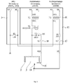
- Figure 1 a schematic representation of a device according to the invention for igniting a vacuum arc discharge according to claim 1 and in Figure 2 the associated schematic circuit diagram is shown.
- FIG. 1 Associated with the embodiment are the Figures 1 and 2 .
- a vacuum chamber 1 ( Figure 1 ) there is a vacuum arc evaporator 2 with a target 3.
- the substrates to be coated are not shown to simplify the illustration and in practice are usually located directly opposite the target 3.
- a gas inlet 5 is present for evacuating the vacuum chamber 1 .
- a sufficient plasma for igniting the vacuum arc discharge can also be provided at process pressures ⁇ 10 -4 mbar can be generated.
- the vacuum chamber 1 is connected to ground 6 and the target 3 is connected to a power source 7.
- the device according to the invention for igniting a vacuum arc discharge is described in more detail below in the application according to the method.
- the technologically necessary process conditions are established by evacuating the vacuum chamber 1 and admitting a process gas with an exemplary pressure of 5x10 -3 mbar via the gas inlet 5 becomes. At this process pressure, it is not necessary for reliable ignition of the vacuum arc discharge to supply additional gas via the gas inlet 19.
- the power source 7 ( Figure 1 and 2 ) set a voltage of 24 VDC with a current of 160 A on target 3, for example.
- an ignition electrode 15 can be connected to a capacitor 16 via the measuring and control device 13, which capacitor can be connected to a separate power supply or at the potential of a low-voltage source, in the example at the current source 7.
- the ignition electrode 15 is arranged in the space between the high-voltage electrode 14 and the target 3 and in the vicinity thereof.
- the high-voltage electrode 14 is connected to the high-voltage source 20 via the measuring and control device 13 and the switch 17.
- a voltage of, for example, 3 kV is thus applied to the high-voltage electrode 14.
- this energy is not sufficient to ignite a vacuum arc discharge. Only when the capacitor 16 is discharged to the ignition electrode 15 via the switch 18 does an ignition power of approximately 70 kW and a dense plasma occur, which causes the formation of a vacuum arc on the target 3
Landscapes
- Physics & Mathematics (AREA)
- Engineering & Computer Science (AREA)
- Plasma & Fusion (AREA)
- Electromagnetism (AREA)
- Spectroscopy & Molecular Physics (AREA)
- Chemical & Material Sciences (AREA)
- Analytical Chemistry (AREA)
- Plasma Technology (AREA)
- Physical Vapour Deposition (AREA)
Description
- Die Erfindung betrifft eine Vorrichtung zum Zünden einer Vakuumbogenentladung mit den Merkmalen nach Anspruch 1 und zugehörigem Verfahren zu deren Anwendung mit den Merkmalen nach Anspruch 4. Die Vorrichtungen dienen insbesondere zur leistungsstarken Beschichtung von funktionellen oder dekorativen Beschichtungen aus verdampfbaren Materialien auf Substraten wie beispielhaft Werkzeuge, Reflektoren oder Dekorelemente.
- Nach dem Stand der Technik sind verschiedene Lösungen zum Zünden einer niederenergetischen Vakuumbogenentladung, auch Lichtbogenentladung genannt, bekannt. Als Stand der Technik sind hier insbesondere Lösungen relevant, die mittels Hilfsplasmaeinrichtungen geeignete Bedingungen zum Zünden der Vakuumbogenentladung schaffen.
- Die
DE 10042629 C2 gibt einen Lichtbogenverdampfer mit einer Kathode, einer Anode und einer Zündeinrichtung an. Die Zündeinrichtung umfasst eine lonenquelle, welche Ionen in den Raum zwischen der Kathode und der Anode einbringt. Die lonenquelle ist vorzugsweise selbst eine Hilfsplasmaeinrichtung, mit der Material zur Bereitstellung der freien Ionen verdampft und in einen Plasmazustand überführt wird. Die Hilfsplasmaeinrichtung ist aus einer Zündelektrode und einer Hilfsanode aufgebaut, die durch einen isolierenden Träger getrennt sind, auf dem sich Material zur Lieferung der freien Ionen befindet. Durch Beaufschlagung mit einem Zündimpuls wird ein starker Stromfluss über den Träger ausgelöst und das Material verdampft und in den Plasmazustand überführt. Eine Lade- und Kontrolleinheit zur Messung der Lichtbogenspannung zwischen der Kathode und der Anode betätigt in Abhängigkeit der gemessenen Lichtbogenspannung die Zündvorrichtung. Die Lichtbogenspannung wird laufend gemessen und bei Erreichen eines kritischen Wertes wird die Zündvorrichtung abermals betätigt, bevor der Lichtbogen erlischt. - In der
DE 101 55 120 A1 wird ein Verfahren und eine Vorrichtung zur Initiierung einer gepulsten Bogenentladung offenbart. Dazu weist die offenbarte Vorrichtung eine mechanische Zündeinrichtung auf, welche auf einer Kreisbahn angeordnete Elektrodensegmente vorsieht. Ein Stromabnehmer wird hierbei über die Elektrodensegmente geführt wobei der Schaltungszustand periodisch zwischen Zu- und Abschalten des Zündplasmas ändert. Somit wird mechanisch die Ausbildung einer Vakuumbogenentladung initiiert. - Der Erfindung liegt als Aufgabe zugrunde, eine Vorrichtung zum Zünden einer Vakuumbogenentladung und Verfahren zu deren Anwendung anzugeben, mit denen eine einfache und sichere Zündung der Vakuumbogenentladung über die gesamte technologisch vorgegebene Betriebszeit gewährleistet ist.
- Der Kern der Erfindung besteht darin, dass mit der erfindungsgemäßen Vorrichtung und ihrer verfahrensgemäßen Anwendung in der Nähe des Targets des Vakuumbogenverdampfers an einer Zündelektrode mittels Hilfsplasmaeinrichtungen eine Zündleistung zwischen 30 und 100 kW, vorzugsweise 70 kW, bereitgestellt wird, die geeignet ist, eine Vakuumbogenentladung am Vakuumbogenverdampfer auszulösen. Dazu werden eine Vorrichtung sowie ein entsprechendes Verfahren zur Anwendung der Vorrichtung angegeben.
- Bei der Vorrichtung nach Anspruch 1 wird eine Hilfsplasmaeinrichtung angegeben, die eine Zündenergie bereitstellt, welche eine Vakuumbogenentladung am Vakuumbogenverdampfer auslöst. Eine Mess- und Steuereinrichtung erfasst und regelt die elektrischen Parameter. Die Bauelemente der Hilfsplasmaeinrichtung sind so ausgelegt, dass eine angegebene Zündleistung an der Zündelektrode bereitgestellt werden kann.
- Zur erstmaligen Zündung eines Vakuumbogens werden in der Vakuumkammer die technologisch vorgegebenen Parameter eingestellt. Das sind insbesondere die erforderliche Art des Prozessgase sowie der Arbeitsdruck. Weiterhin ist der erforderliche Strom für das Target einzustellen. Obwohl danach alle für eine Vakuumbogenverdampfung erforderlichen Betriebsparameter gegeben sind, kommt es nicht zur Zündung eines Vakuumbogens. Dafür ist eine Zündvorrichtung erforderlich. Erfindungsgemäß wird eine Hilfsplasmaeinrichtung angegeben, die über eine Hochspannungsquelle, einen Kondensator sowie eine Zündelektrode in der Nähe des Targets verfügt, wobei verfahrensgemäß an der Zündelektrode eine Zündleistung zwischen 30 und 100 kW, vorzugsweise 70 kW, bereitgestellt wird. Der angegebene relativ große Bereich einer Zündleistung zwischen 30 und 100 kW ergibt sich aus den vielseitigen unterschiedlichen Konfigurationen der einzelnen Vakuumbogenverdampfer in der Praxis. In einzelnen Fällen kann es vorteilhaft sein, den Bereich auch nach oben oder unten auszudehnen.
- Nach Anspruch 1 weist die Hilfsplasmaeinrichtung eine Hochspannungsquelle auf, die mit einer Hochspannungselektrode verbunden werden kann. Im Raum zwischen der Hochspannungselektrode und dem Target ist die Zündelektrode vorhanden, die ihrerseits mit einem Kondensator verbunden werden kann, der mit einer Niederspannungsquelle, z.B. der Stromquelle für den Vakuumbogen verbunden ist. Die Erfassung der aktuellen elektrischen Parameter erfolgt ebenfalls über eine Mess- und Steuereinrichtung, die in der Folge die elektrischen Parameter regelt, d.h. insbesondere den Kondensator lädt und zur gegebenen Zeit zur Zündelektrode hin entlädt. Die Hochspannungselektrode kann dabei permanent an der Hochspannungsquelle anliegen oder von der Mess- und Steuereinrichtung nur bei Bedarf zugeschaltet werden.
- Der Vorteil der Ausführung nach Anspruch 1 besteht darin, dass für die Hochspannungsquelle geringere Leistungen ermöglicht werden, da der Energieanteil, der über den Kondensator bereitgestellt werden muss, aus einer Niederspannungsquelle gezogen werden kann. Damit können die technischen Aufwendungen für den Hochspannungsteil gesenkt werden.
- Gegenüber dem Stand der Technik besteht der Vorteil der Erfindung darin, dass keine mechanisch bewegten Zündvorrichtungen mit ihrem hohen Verschleiß oder Leitpasten und ähnliche Metalldampf bildende Plasmen erforderlich sind.
- Die Erfindung realisiert in der Nähe des Targets ein zeitlich und örtlich begrenztes dichtes Plasma mit den gegebenen Prozessgasen, welches eine derartige Dichte aufweist, dass am Target ein Vakuumbogen ausgelöst wird. Außer der Hochspannungsquelle, einem Hochspannung- bzw. (Niederspannung-)Kondensator, einer Zündelektrode und nach Anspruch 1 einer Hochspannungselektrode sind keine weiteren Elemente erforderlich. Die Mess- und Steuereinrichtung ist allgemein bei allen Lösungen auch nach dem Stand der Technik bereits vorhanden.
- Die Erfindung wird nachstehend an einem Ausführungsbeispiel näher erläutert. Zugehörig zeigt die
Figur 1 eine schematische Darstellung einer erfindungsgemäßen Vorrichtung zum Zünden einer Vakuumbogenentladung nach Anspruch 1 und inFigur 2 wird der zugehörige schematische Schaltplan dargestellt. - Zugehörig zum Ausführungsbeispiel sind die
Figuren 1 und2 . In einer Vakuumkammer 1 (Figur 1 ) befindet sich ein Vakuumbogenverdampfer 2 mit einem Target 3. Die zu beschichtenden Substrate sind zur Vereinfachung der Darstellung nicht dargestellt und befinden sich in der Praxis in der Regel direkt gegenüber dem Target 3. Zur Evakuierung der Vakuumkammer 1 ist ein Vakuumanschluss 4 und zum Einlass eines oder mehrerer Prozessgase ein Gaseinlass 5 vorhanden. Mit einem zusätzlichen Gaseinlass 19, partiell im Bereich der Zündelektroden, kann ein ausreichendes Plasma für die Zündung der Vakuumbogenentladung auch bei Prozessdrücken <10-4 mbar erzeugt werden. Die Vakuumkammer 1 liegt an Masse 6 und das Target 3 an einer Stromquelle 7. - Nachfolgend wird die erfindungsgemäße Vorrichtung zum Zünden einer Vakuumbogenentladung in der verfahrensgemäßen Anwendung näher beschrieben. Nachdem das Target 3 in dem Vakuumbogenverdampfer positioniert ist sowie die zu beschichtenden Substrate in den Vakuumkammer 1 eingerichtet wurden, werden die technologisch erforderlichen Prozessbedingen hergestellt, indem die Vakuumkammer 1 evakuiert und über den Gaseinlass 5 ein Prozessgas mit einem beispielhaften Druck von 5x10⁻³ mbar eingelassen wird. Bei diesem Prozessdruck ist es für eine sichere Zündung der Vakuumbogenentladung nicht erforderlich, zusätzliches Gas über den Gaseinlass 19 zuzuführen.
- Der Betrieb des Vakuumbogenverdampfers 2 wird vorbereitet. Dazu wird über die Stromquelle 7 (
Figur 1 und2 ) beispielhaft am Target 3 eine Spannung von 24 VDC mit einem Strom von 160 A eingestellt. - Als Hilfsplasmaeinrichtung sind eine Hochspannungsquelle 20 vorhanden, die über eine Mess- und Steuereinrichtung 13 mit einer anodischen Hochspannungselektrode 14 verbunden werden kann. Parallel kann über die Mess- und Steuereinrichtung 13 eine Zündelektrode 15 mit einem Kondensator 16 verbunden werden, der mit einer gesonderten Stromversorgung verbunden oder am Potential einer Niederspannungsquelle, im Beispiel an der Stromquelle 7, liegen kann. Die Zündelektrode 15 ist im Raum zwischen der Hochspannungselektrode 14 und dem Target 3 und in dessen räumlicher Nähe angeordnet.
- Verfahrensgemäß wird zum erstmaligen Start der Vakuumbogenentladung über die Mess- und Steuereinrichtung 13 und den Schalter 17 die Hochspannungselektrode 14 mit der Hochspannungsquelle 20 verbunden. An der Hochspannungselektrode 14 liegt somit eine Spannung von beispielhaft 3 kV an. Diese Energie reicht jedoch nicht zur Zündung einer Vakuumbogenentladung aus. Erst wenn über den Schalter 18 der Kondensator 16 zur Zündelektrode 15 hin entladen wird, kommt es zu einer Zündleistung von etwa 70 kW und einem dichten Plasma, welches die Ausbildung eines Vakuumbogens am Target 3 bewirkt
-
- 1
- Vakuumkammer
- 2
- Vakuumbogenverdampfer
- 3
- Target
- 4
- Vakuumanschluss
- 5
- Gaseinlass
- 6
- Masse
- 7
- Stromquelle
- 13
- Mess- und Steuereinrichtung
- 14
- Hochspannungselektrode
- 15
- Zündelektrode
- 16
- Kondensator
- 17
- Schalter
- 18
- Schalter
- 19
- Gaseinlass, partiell im Bereich der Zündelektroden
- 20
- Hochspannungsquelle
Claims (5)
- Vorrichtung zum Zünden einer Vakuumbogenentladung mit einem in einer Vakuumkammer (1) angeordneten und ein Target (3) aufweisenden Vakuumbogenverdampfer, wobei zwischen dem als Kathode geschalteten Target (3) und einer anodischen Hochspannungselektrode (14) eines Vakuumbogenverdampfers (2) mittels einer Hilfsplasmaeinrichtung eine Vakuumbogenentladung ausbildbar ist, wobei die Hilfsplasmaeinrichtung eine Zündelektrode (15) aufweist, wobei- die Hilfsplasmaeinrichtung eine Hochspannungsquelle (20) aufweist,- die mit der anodischen Hochspannungselektrode (14) verbunden werden kann,- dass die Zündelektrode (15) im Raum zwischen dem Target (3) und der Hochspannungselektrode (14) angeordnet ist,- dass ein Kondensator (16) vorhanden ist, der zur Zündelektrode (15) hin entladen werden kann, und- dass die Zündelektrode (15) sowie die Hochspannungselektrode (14) mit einer Mess- und Steuereinrichtung (13) zur Erfassung und Regelung der elektrischen Parameter kontaktiert sind.
- Vorrichtung zum Zünden einer Vakuumbogenentladung nach Anspruch 1, wobei die Hochspannungsquelle (20) geeignet ist, über die Mess- und Steuereinrichtung (13) eine Hochspannung mit einer AC- oder DC-Leistung größer 10 W an der Hochspannungselektrode (14) bereitzustellen.
- Vorrichtung zum Zünden einer Vakuumbogenentladung nach Anspruch 2, wobei der Kondensator (16) geeignet ist, über die Mess- und Steuereinrichtung (13) an die Zündelektrode (15) eine Zündleistung abzugeben, die in Überlagerung mit dem AC- oder DC-Plasma an der Hochspannungselektrode (14) einen Zündimpuls mit einer Zündleistung zwischen 30 und 100 kW, vorzugsweise 70 kW, erzeugt.
- Verfahren zur Anwendung der Vorrichtung zum Zünden einer Vakuumbogenentladung nach Anspruch 1, bei dem nach Einstellung der erforderlichen Prozessparameter in der Vakuumkammer (1) und der elektrischen Verfahrensparameter am Vakuumbogenverdampfer (2) mittels der Hilfplasmaeinrichtung die Hochspannungsquelle (20) zwischen der Hochspannungselektrode (14) und dem Target (3) ein Plasma erzeugt, welches unmittelbar nicht geeignet ist, eine Vakuumbogenentladung am Vakuumbogenverdampfer (2) auszulösen, und dass nachfolgend mittels der Mess- und Schalteinrichtung (13) vom Kondensator (16) zur Zündelektrode (15) hin eine Kondensatorentladung ausgelöst wird, wodurch eine Zündleistung zwischen 30 und 100 kW, vorzugsweise 70 kW, ausgebildet wird, wobei diese geeignet ist, eine Vakuumbogenentladung am Vakuumbogenverdampfer (2) auszulösen.
- Verfahren nach Anspruch 4, wobei nach Zündung der Vakuumbogenentladung am Vakuumbogenverdampfer (2) der Kondensator (16) über die Mess- und Steuereinrichtung (13) von der Zündelektrode (15) elektrisch getrennt und wieder aufgeladen wird.
Applications Claiming Priority (2)
| Application Number | Priority Date | Filing Date | Title |
|---|---|---|---|
| DE102015113104.8A DE102015113104A1 (de) | 2015-08-09 | 2015-08-09 | Vorrichtung zum Zünden einer Vakuumbogenentladung und Verfahren zu deren Anwendung |
| DE202015104164.0U DE202015104164U1 (de) | 2015-08-09 | 2015-08-09 | Vorrichtung zum Zünden einer Vakuumbogenentladung |
Publications (2)
| Publication Number | Publication Date |
|---|---|
| EP3133634A1 EP3133634A1 (de) | 2017-02-22 |
| EP3133634B1 true EP3133634B1 (de) | 2020-09-30 |
Family
ID=56943300
Family Applications (1)
| Application Number | Title | Priority Date | Filing Date |
|---|---|---|---|
| EP16183036.9A Active EP3133634B1 (de) | 2015-08-09 | 2016-08-05 | Vorrichtung zum zünden einer vakuumbogenentladung und verfahren zu deren anwendung |
Country Status (1)
| Country | Link |
|---|---|
| EP (1) | EP3133634B1 (de) |
Citations (1)
| Publication number | Priority date | Publication date | Assignee | Title |
|---|---|---|---|---|
| DE10155120A1 (de) * | 2001-11-09 | 2003-05-28 | Ernst Klinkenberg | Verfahren und Vorrichtung zur Beschichtung eines Substrats durch eine verteilt initiierte gepulste kathodische Bogenerosion einer Opferelektrode |
Family Cites Families (4)
| Publication number | Priority date | Publication date | Assignee | Title |
|---|---|---|---|---|
| DE2046235A1 (de) * | 1970-09-18 | 1972-03-23 | Linde Ag | Verfahren und Vorrichtung zum Zünden von Schweißlichtbögen |
| EP0174977A4 (de) * | 1984-03-02 | 1987-02-12 | Univ Minnesota | Verfahren und vorrichtung zum gesteuerten aufbringen von material mittels lichtbogen im vakuum. |
| US4610775A (en) * | 1985-07-26 | 1986-09-09 | Westinghouse Electric Corp. | Method and apparatus for clearing short-circuited, high-voltage cathodes in a sputtering chamber |
| DE10042629C2 (de) | 2000-08-30 | 2003-08-28 | Angaris Gmbh | Zündvorrichtung für einen Lichtbogenverdampfer |
-
2016
- 2016-08-05 EP EP16183036.9A patent/EP3133634B1/de active Active
Patent Citations (1)
| Publication number | Priority date | Publication date | Assignee | Title |
|---|---|---|---|---|
| DE10155120A1 (de) * | 2001-11-09 | 2003-05-28 | Ernst Klinkenberg | Verfahren und Vorrichtung zur Beschichtung eines Substrats durch eine verteilt initiierte gepulste kathodische Bogenerosion einer Opferelektrode |
Also Published As
| Publication number | Publication date |
|---|---|
| EP3133634A1 (de) | 2017-02-22 |
Similar Documents
| Publication | Publication Date | Title |
|---|---|---|
| EP1248499B1 (de) | Verfahren und Vorrichtung zum Erzeugen von extrem ultravioletter Strahlung | |
| DE19941670A1 (de) | Massenspektrometer | |
| DE2026321A1 (de) | Kathodenaufstäubungsverfahren und Vorrichtung zur Durchführung des Verfahrens | |
| DE1640255A1 (de) | Funkenstreckenschalter | |
| DE2602078B2 (de) | Niederdruck-gasentladungsroehre | |
| DE1911424A1 (de) | Verfahren zum Bearbeiten von Werkstuecken mittels Unterwasser-Druckstoessen | |
| EP3133634B1 (de) | Vorrichtung zum zünden einer vakuumbogenentladung und verfahren zu deren anwendung | |
| DE102015113104A1 (de) | Vorrichtung zum Zünden einer Vakuumbogenentladung und Verfahren zu deren Anwendung | |
| DE3874386T2 (de) | Vakuum-lichtbogen-ionenquelle. | |
| EP1145269B1 (de) | Verfahren zur erzeugung eines gepulsten elektronenstrahls und triggerplasmaquelle zur durchführung des verfahrens | |
| DE202015104164U1 (de) | Vorrichtung zum Zünden einer Vakuumbogenentladung | |
| DE3142900C2 (de) | ||
| WO2003105543A2 (de) | Verfahren und einrichtung zur reduzierung der zündspannung von plasmen | |
| DE1640240A1 (de) | Steuerbares Vakuumschaltgeraet | |
| DE1539151C (de) | Ionen-Getterpumpe | |
| DE10155120A1 (de) | Verfahren und Vorrichtung zur Beschichtung eines Substrats durch eine verteilt initiierte gepulste kathodische Bogenerosion einer Opferelektrode | |
| EP0497126A1 (de) | Schaltungsanordnung zum Zünden und Betreiben einer Hohlkatodenbogenentladung | |
| EP4331002B1 (de) | Hohlkathodensystem zum erzeugen eines plasmas und verfahren zum betreiben eines solchen hohlkathodensystems | |
| DE102009025422B4 (de) | Verfahren und Anordnung zur Steuerung eines RF-Generators für Magnetrons in Vakuumbeschichtungsanlagen | |
| EP1123641A1 (de) | Gasgefüllter teilchenbeschleuniger mit einer gepulsten plasmaquelle | |
| DE2025987A1 (de) | Ionenquelle | |
| DD217074B1 (de) | Verfahren und vorrichtung zur lichtbogenformierung von elektrodenoberflaechen in vakuumschaltkammern | |
| DE563139C (de) | Einrichtung zur Aufrechterhaltung des Vakuums in Hochvakuumgefaessen, insbesondere Hochvakuumschaltern | |
| DE1765609C (de) | Hochfrequenz-Sprühvorrichtung | |
| DE1765185C3 (de) | Vorrichtung zur Kathodenzerstäubung |
Legal Events
| Date | Code | Title | Description |
|---|---|---|---|
| PUAI | Public reference made under article 153(3) epc to a published international application that has entered the european phase |
Free format text: ORIGINAL CODE: 0009012 |
|
| STAA | Information on the status of an ep patent application or granted ep patent |
Free format text: STATUS: THE APPLICATION HAS BEEN PUBLISHED |
|
| AK | Designated contracting states |
Kind code of ref document: A1 Designated state(s): AL AT BE BG CH CY CZ DE DK EE ES FI FR GB GR HR HU IE IS IT LI LT LU LV MC MK MT NL NO PL PT RO RS SE SI SK SM TR |
|
| AX | Request for extension of the european patent |
Extension state: BA ME |
|
| STAA | Information on the status of an ep patent application or granted ep patent |
Free format text: STATUS: REQUEST FOR EXAMINATION WAS MADE |
|
| 17P | Request for examination filed |
Effective date: 20170803 |
|
| RBV | Designated contracting states (corrected) |
Designated state(s): AL AT BE BG CH CY CZ DE DK EE ES FI FR GB GR HR HU IE IS IT LI LT LU LV MC MK MT NL NO PL PT RO RS SE SI SK SM TR |
|
| REG | Reference to a national code |
Ref country code: HK Ref legal event code: DE Ref document number: 1234893 Country of ref document: HK |
|
| STAA | Information on the status of an ep patent application or granted ep patent |
Free format text: STATUS: EXAMINATION IS IN PROGRESS |
|
| 17Q | First examination report despatched |
Effective date: 20190524 |
|
| GRAP | Despatch of communication of intention to grant a patent |
Free format text: ORIGINAL CODE: EPIDOSNIGR1 |
|
| STAA | Information on the status of an ep patent application or granted ep patent |
Free format text: STATUS: GRANT OF PATENT IS INTENDED |
|
| INTG | Intention to grant announced |
Effective date: 20200310 |
|
| GRAJ | Information related to disapproval of communication of intention to grant by the applicant or resumption of examination proceedings by the epo deleted |
Free format text: ORIGINAL CODE: EPIDOSDIGR1 |
|
| STAA | Information on the status of an ep patent application or granted ep patent |
Free format text: STATUS: EXAMINATION IS IN PROGRESS |
|
| GRAP | Despatch of communication of intention to grant a patent |
Free format text: ORIGINAL CODE: EPIDOSNIGR1 |
|
| STAA | Information on the status of an ep patent application or granted ep patent |
Free format text: STATUS: GRANT OF PATENT IS INTENDED |
|
| INTC | Intention to grant announced (deleted) | ||
| GRAS | Grant fee paid |
Free format text: ORIGINAL CODE: EPIDOSNIGR3 |
|
| GRAA | (expected) grant |
Free format text: ORIGINAL CODE: 0009210 |
|
| STAA | Information on the status of an ep patent application or granted ep patent |
Free format text: STATUS: THE PATENT HAS BEEN GRANTED |
|
| INTG | Intention to grant announced |
Effective date: 20200803 |
|
| AK | Designated contracting states |
Kind code of ref document: B1 Designated state(s): AL AT BE BG CH CY CZ DE DK EE ES FI FR GB GR HR HU IE IS IT LI LT LU LV MC MK MT NL NO PL PT RO RS SE SI SK SM TR |
|
| REG | Reference to a national code |
Ref country code: CH Ref legal event code: EP Ref country code: GB Ref legal event code: FG4D Free format text: NOT ENGLISH |
|
| REG | Reference to a national code |
Ref country code: DE Ref legal event code: R096 Ref document number: 502016011298 Country of ref document: DE Ref country code: AT Ref legal event code: REF Ref document number: 1319656 Country of ref document: AT Kind code of ref document: T Effective date: 20201015 |
|
| REG | Reference to a national code |
Ref country code: IE Ref legal event code: FG4D Free format text: LANGUAGE OF EP DOCUMENT: GERMAN |
|
| RAP2 | Party data changed (patent owner data changed or rights of a patent transferred) |
Owner name: ISA INSTALLATIONS-, STEUERUNGS- UND AUTOMATISIERUNGSSYSTEM GMBH Owner name: VTD VAKUUMTECHNIK DRESDEN GMBH |
|
| PG25 | Lapsed in a contracting state [announced via postgrant information from national office to epo] |
Ref country code: FI Free format text: LAPSE BECAUSE OF FAILURE TO SUBMIT A TRANSLATION OF THE DESCRIPTION OR TO PAY THE FEE WITHIN THE PRESCRIBED TIME-LIMIT Effective date: 20200930 Ref country code: HR Free format text: LAPSE BECAUSE OF FAILURE TO SUBMIT A TRANSLATION OF THE DESCRIPTION OR TO PAY THE FEE WITHIN THE PRESCRIBED TIME-LIMIT Effective date: 20200930 Ref country code: NO Free format text: LAPSE BECAUSE OF FAILURE TO SUBMIT A TRANSLATION OF THE DESCRIPTION OR TO PAY THE FEE WITHIN THE PRESCRIBED TIME-LIMIT Effective date: 20201230 Ref country code: SE Free format text: LAPSE BECAUSE OF FAILURE TO SUBMIT A TRANSLATION OF THE DESCRIPTION OR TO PAY THE FEE WITHIN THE PRESCRIBED TIME-LIMIT Effective date: 20200930 Ref country code: BG Free format text: LAPSE BECAUSE OF FAILURE TO SUBMIT A TRANSLATION OF THE DESCRIPTION OR TO PAY THE FEE WITHIN THE PRESCRIBED TIME-LIMIT Effective date: 20201230 Ref country code: GR Free format text: LAPSE BECAUSE OF FAILURE TO SUBMIT A TRANSLATION OF THE DESCRIPTION OR TO PAY THE FEE WITHIN THE PRESCRIBED TIME-LIMIT Effective date: 20201231 |
|
| PG25 | Lapsed in a contracting state [announced via postgrant information from national office to epo] |
Ref country code: RS Free format text: LAPSE BECAUSE OF FAILURE TO SUBMIT A TRANSLATION OF THE DESCRIPTION OR TO PAY THE FEE WITHIN THE PRESCRIBED TIME-LIMIT Effective date: 20200930 Ref country code: LV Free format text: LAPSE BECAUSE OF FAILURE TO SUBMIT A TRANSLATION OF THE DESCRIPTION OR TO PAY THE FEE WITHIN THE PRESCRIBED TIME-LIMIT Effective date: 20200930 |
|
| REG | Reference to a national code |
Ref country code: NL Ref legal event code: MP Effective date: 20200930 |
|
| REG | Reference to a national code |
Ref country code: LT Ref legal event code: MG4D |
|
| PG25 | Lapsed in a contracting state [announced via postgrant information from national office to epo] |
Ref country code: CZ Free format text: LAPSE BECAUSE OF FAILURE TO SUBMIT A TRANSLATION OF THE DESCRIPTION OR TO PAY THE FEE WITHIN THE PRESCRIBED TIME-LIMIT Effective date: 20200930 Ref country code: PT Free format text: LAPSE BECAUSE OF FAILURE TO SUBMIT A TRANSLATION OF THE DESCRIPTION OR TO PAY THE FEE WITHIN THE PRESCRIBED TIME-LIMIT Effective date: 20210201 Ref country code: RO Free format text: LAPSE BECAUSE OF FAILURE TO SUBMIT A TRANSLATION OF THE DESCRIPTION OR TO PAY THE FEE WITHIN THE PRESCRIBED TIME-LIMIT Effective date: 20200930 Ref country code: SM Free format text: LAPSE BECAUSE OF FAILURE TO SUBMIT A TRANSLATION OF THE DESCRIPTION OR TO PAY THE FEE WITHIN THE PRESCRIBED TIME-LIMIT Effective date: 20200930 Ref country code: LT Free format text: LAPSE BECAUSE OF FAILURE TO SUBMIT A TRANSLATION OF THE DESCRIPTION OR TO PAY THE FEE WITHIN THE PRESCRIBED TIME-LIMIT Effective date: 20200930 Ref country code: NL Free format text: LAPSE BECAUSE OF FAILURE TO SUBMIT A TRANSLATION OF THE DESCRIPTION OR TO PAY THE FEE WITHIN THE PRESCRIBED TIME-LIMIT Effective date: 20200930 Ref country code: EE Free format text: LAPSE BECAUSE OF FAILURE TO SUBMIT A TRANSLATION OF THE DESCRIPTION OR TO PAY THE FEE WITHIN THE PRESCRIBED TIME-LIMIT Effective date: 20200930 |
|
| PG25 | Lapsed in a contracting state [announced via postgrant information from national office to epo] |
Ref country code: ES Free format text: LAPSE BECAUSE OF FAILURE TO SUBMIT A TRANSLATION OF THE DESCRIPTION OR TO PAY THE FEE WITHIN THE PRESCRIBED TIME-LIMIT Effective date: 20200930 Ref country code: AL Free format text: LAPSE BECAUSE OF FAILURE TO SUBMIT A TRANSLATION OF THE DESCRIPTION OR TO PAY THE FEE WITHIN THE PRESCRIBED TIME-LIMIT Effective date: 20200930 Ref country code: IS Free format text: LAPSE BECAUSE OF FAILURE TO SUBMIT A TRANSLATION OF THE DESCRIPTION OR TO PAY THE FEE WITHIN THE PRESCRIBED TIME-LIMIT Effective date: 20210130 Ref country code: PL Free format text: LAPSE BECAUSE OF FAILURE TO SUBMIT A TRANSLATION OF THE DESCRIPTION OR TO PAY THE FEE WITHIN THE PRESCRIBED TIME-LIMIT Effective date: 20200930 |
|
| PG25 | Lapsed in a contracting state [announced via postgrant information from national office to epo] |
Ref country code: SK Free format text: LAPSE BECAUSE OF FAILURE TO SUBMIT A TRANSLATION OF THE DESCRIPTION OR TO PAY THE FEE WITHIN THE PRESCRIBED TIME-LIMIT Effective date: 20200930 |
|
| REG | Reference to a national code |
Ref country code: DE Ref legal event code: R097 Ref document number: 502016011298 Country of ref document: DE |
|
| PLBE | No opposition filed within time limit |
Free format text: ORIGINAL CODE: 0009261 |
|
| STAA | Information on the status of an ep patent application or granted ep patent |
Free format text: STATUS: NO OPPOSITION FILED WITHIN TIME LIMIT |
|
| PG25 | Lapsed in a contracting state [announced via postgrant information from national office to epo] |
Ref country code: DK Free format text: LAPSE BECAUSE OF FAILURE TO SUBMIT A TRANSLATION OF THE DESCRIPTION OR TO PAY THE FEE WITHIN THE PRESCRIBED TIME-LIMIT Effective date: 20200930 |
|
| 26N | No opposition filed |
Effective date: 20210701 |
|
| PG25 | Lapsed in a contracting state [announced via postgrant information from national office to epo] |
Ref country code: IT Free format text: LAPSE BECAUSE OF FAILURE TO SUBMIT A TRANSLATION OF THE DESCRIPTION OR TO PAY THE FEE WITHIN THE PRESCRIBED TIME-LIMIT Effective date: 20200930 |
|
| PG25 | Lapsed in a contracting state [announced via postgrant information from national office to epo] |
Ref country code: SI Free format text: LAPSE BECAUSE OF FAILURE TO SUBMIT A TRANSLATION OF THE DESCRIPTION OR TO PAY THE FEE WITHIN THE PRESCRIBED TIME-LIMIT Effective date: 20200930 |
|
| PG25 | Lapsed in a contracting state [announced via postgrant information from national office to epo] |
Ref country code: MC Free format text: LAPSE BECAUSE OF FAILURE TO SUBMIT A TRANSLATION OF THE DESCRIPTION OR TO PAY THE FEE WITHIN THE PRESCRIBED TIME-LIMIT Effective date: 20200930 |
|
| REG | Reference to a national code |
Ref country code: BE Ref legal event code: MM Effective date: 20210831 |
|
| GBPC | Gb: european patent ceased through non-payment of renewal fee |
Effective date: 20210805 |
|
| PG25 | Lapsed in a contracting state [announced via postgrant information from national office to epo] |
Ref country code: IS Free format text: LAPSE BECAUSE OF FAILURE TO SUBMIT A TRANSLATION OF THE DESCRIPTION OR TO PAY THE FEE WITHIN THE PRESCRIBED TIME-LIMIT Effective date: 20210130 Ref country code: LU Free format text: LAPSE BECAUSE OF NON-PAYMENT OF DUE FEES Effective date: 20210805 |
|
| PG25 | Lapsed in a contracting state [announced via postgrant information from national office to epo] |
Ref country code: IE Free format text: LAPSE BECAUSE OF NON-PAYMENT OF DUE FEES Effective date: 20210805 Ref country code: GB Free format text: LAPSE BECAUSE OF NON-PAYMENT OF DUE FEES Effective date: 20210805 Ref country code: FR Free format text: LAPSE BECAUSE OF NON-PAYMENT OF DUE FEES Effective date: 20210831 Ref country code: BE Free format text: LAPSE BECAUSE OF NON-PAYMENT OF DUE FEES Effective date: 20210831 |
|
| REG | Reference to a national code |
Ref country code: DE Ref legal event code: R082 Ref document number: 502016011298 Country of ref document: DE |
|
| PG25 | Lapsed in a contracting state [announced via postgrant information from national office to epo] |
Ref country code: HU Free format text: LAPSE BECAUSE OF FAILURE TO SUBMIT A TRANSLATION OF THE DESCRIPTION OR TO PAY THE FEE WITHIN THE PRESCRIBED TIME-LIMIT; INVALID AB INITIO Effective date: 20160805 |
|
| PG25 | Lapsed in a contracting state [announced via postgrant information from national office to epo] |
Ref country code: CY Free format text: LAPSE BECAUSE OF FAILURE TO SUBMIT A TRANSLATION OF THE DESCRIPTION OR TO PAY THE FEE WITHIN THE PRESCRIBED TIME-LIMIT Effective date: 20200930 |
|
| REG | Reference to a national code |
Ref country code: HK Ref legal event code: WD Ref document number: 1234893 Country of ref document: HK |
|
| PG25 | Lapsed in a contracting state [announced via postgrant information from national office to epo] |
Ref country code: MK Free format text: LAPSE BECAUSE OF FAILURE TO SUBMIT A TRANSLATION OF THE DESCRIPTION OR TO PAY THE FEE WITHIN THE PRESCRIBED TIME-LIMIT Effective date: 20200930 |
|
| PG25 | Lapsed in a contracting state [announced via postgrant information from national office to epo] |
Ref country code: MT Free format text: LAPSE BECAUSE OF FAILURE TO SUBMIT A TRANSLATION OF THE DESCRIPTION OR TO PAY THE FEE WITHIN THE PRESCRIBED TIME-LIMIT Effective date: 20200930 |
|
| PGFP | Annual fee paid to national office [announced via postgrant information from national office to epo] |
Ref country code: DE Payment date: 20240819 Year of fee payment: 9 |
|
| PGFP | Annual fee paid to national office [announced via postgrant information from national office to epo] |
Ref country code: CH Payment date: 20240901 Year of fee payment: 9 |
|
| PGFP | Annual fee paid to national office [announced via postgrant information from national office to epo] |
Ref country code: AT Payment date: 20240819 Year of fee payment: 9 |
|
| PG25 | Lapsed in a contracting state [announced via postgrant information from national office to epo] |
Ref country code: TR Free format text: LAPSE BECAUSE OF FAILURE TO SUBMIT A TRANSLATION OF THE DESCRIPTION OR TO PAY THE FEE WITHIN THE PRESCRIBED TIME-LIMIT Effective date: 20200930 |