EP3133462A1 - Thermostatventil mit zwangsführung aufweisender abdeckkappe - Google Patents
Thermostatventil mit zwangsführung aufweisender abdeckkappe Download PDFInfo
- Publication number
- EP3133462A1 EP3133462A1 EP16182300.0A EP16182300A EP3133462A1 EP 3133462 A1 EP3133462 A1 EP 3133462A1 EP 16182300 A EP16182300 A EP 16182300A EP 3133462 A1 EP3133462 A1 EP 3133462A1
- Authority
- EP
- European Patent Office
- Prior art keywords
- cap
- housing
- adjusting unit
- mixer cartridge
- positive connection
- Prior art date
- Legal status (The legal status is an assumption and is not a legal conclusion. Google has not performed a legal analysis and makes no representation as to the accuracy of the status listed.)
- Granted
Links
Images


Classifications
-
- G—PHYSICS
- G05—CONTROLLING; REGULATING
- G05D—SYSTEMS FOR CONTROLLING OR REGULATING NON-ELECTRIC VARIABLES
- G05D23/00—Control of temperature
- G05D23/01—Control of temperature without auxiliary power
- G05D23/13—Control of temperature without auxiliary power by varying the mixing ratio of two fluids having different temperatures
- G05D23/1306—Control of temperature without auxiliary power by varying the mixing ratio of two fluids having different temperatures for liquids
- G05D23/132—Control of temperature without auxiliary power by varying the mixing ratio of two fluids having different temperatures for liquids with temperature sensing element
- G05D23/134—Control of temperature without auxiliary power by varying the mixing ratio of two fluids having different temperatures for liquids with temperature sensing element measuring the temperature of mixed fluid
- G05D23/1346—Control of temperature without auxiliary power by varying the mixing ratio of two fluids having different temperatures for liquids with temperature sensing element measuring the temperature of mixed fluid with manual temperature setting means
Definitions
- the present invention relates to a sanitary thermostatic mixing valve with a arranged in a housing, a thermostat element having mixer cartridge which defines a desired temperature of the mixed water, wherein the height of the set temperature can be adjusted by acting on a stop for the thermostatic element of the thermostatic adjusting unit, via the one Cover cap is slipped.
- thermostatic mixing valves sometimes require that the Thermostatic Mixing Valve be flushed with hot water to kill Legionella from time to time.
- the cap is removed from the thermostatic mixing valve and increases the mixed water temperature by operating the adjustment.
- the adjustment unit In order to set the setpoint temperature again after rinsing with hot water, the adjustment unit must once again assume the position corresponding to the setpoint temperature, which can only take place by determining the temperature of the mixed water. After rinsing with hot water so consuming the monitoring of the mixed water temperature corresponding to the setpoint temperature position of the adjustment must be found.
- thermostatic mixing valve with the features mentioned is out DE 10 2004 050 996 B4 in which the stop for the thermostatic element can be displaced in the axial direction by means of an adjustment handle to be grasped as an adjusting unit for changing the height of the setpoint temperature of the mixed water. So that the thermostatic mixing valve can be rinsed exclusively with hot water, a flushing member is provided, which can lift off the stop by means of a starter lever. After actuation of the flushing member, the stop returns to the position predetermined by the setting handle for the set temperature. In such a thermostatic mixing valve so an additional tool for hot water flushing is required.
- a control handle for a thermostatic mixing valve is off DE 195 45 587 A1 known in which a cap of the handle is arranged in a deferred position with an axial projection in a Ringnutbogen collaborate. In the deferred position, a rotational movement of the cap is limited by the ends of the Ringnutbogenyogs, so that a minimum and maximum mixed water temperature is predetermined by the so formed by the Ringnutbogen flourish attacks. The mixed water temperature can thus be changed unintentionally continuously in the deferred position of the cap.
- Another control knob for a water valve is off DE 10 2006 045 540 A1 known.
- Object of the present invention is therefore to solve the problems described with reference to the prior art, at least partially and in particular to provide a thermostatic mixing valve, with which the setpoint temperature after a hot rinse is set securely again without the aid of additional tools.
- thermostatic valve having the features of the independent claim.
- Advantageous developments of the thermostatic mixing valve are given in the dependent claims and the description, wherein features of advantageous developments in a technologically meaningful manner are combined with each other.
- a sanitary thermostatic mixing valve with the features mentioned, wherein the cap is rotatably guided on the adjusting unit by means of a positive guide in particular in the axial direction and the cap is also rotatably fixed by means of a positive connection to the housing or on the mixer cartridge such the cover cap can only be secured to the housing or to the mixer cartridge if the adjustment unit is in a position which predetermines the setpoint temperature of the mixed water by virtue of the positive guidance of the cover cap with the adjustment unit and the positive connection of the cover cap with the housing or with the mixer cartridge.
- the positive guidance between the cover cap and the adjusting unit is formed by a tongue-and-groove guide running in the axial direction on an inner peripheral surface of the cover cap and an outer peripheral surface of the adjusting unit. So it is either the groove on the adjustment and the spring on the cap or the groove on the cap and the spring formed on the adjustment.
- the cap both rotationally fixed to the adjustment and rotatably and positively on the housing or on the Mixer cartridge can be fixed, wherein the connection between the cap and adjusting and the connection between the cap and the housing or mixer cartridge are formed so that the cap on the housing or the mixer cartridge can only be fixed when the adjustment assumes a predetermined position. Since the position of the adjustment directly specifies the position of the stop for the thermostatic element of the mixer cartridge, the per se removable cap can only be completely slipped over the adjustment and fixed to the housing or on the mixer cartridge when the desired set temperature adjusted by the position of the adjustment is.
- the cap After rinsing with hot water, the cap can therefore only be completely slipped over the adjustment and fixed to the housing or to the mixer cartridge when the adjustment has taken the position for the desired temperature of the mixed water.
- the cap When slipping over the cap can be initially only partially slipped over on the adjustment, in which case the cover with the adjustment are already connected to each other due to the at least partially formed forced operation.
- the cap with the adjustment can then be rotated until the positive connection of the cap with the housing or with the mixer cartridge is produced and the target temperature is thus set.
- the housing of the thermostatic mixing valve has in particular a cold water inlet and a hot water inlet and a mixed water drain.
- the mixer cartridge has the stop against which the at least partially surrounded by the mixing water thermostatic element is supported.
- the thermostatic element in turn acts on a control element, which regulates the proportion of water from the cold water inlet and the hot water inlet.
- the circulated by the mixed water thermostatic element expands depending on the temperature of the mixed water or contracts, so that via the control element required for the target temperature ratio is adjusted by cold water and hot water.
- the adjusting unit comprises all elements which can directly or indirectly change the position of the stop in the mixer cartridge. At least some of these elements of the adjustment project beyond the housing on one side.
- the covering cap is slipped over these elements.
- the mixer cartridge also includes other elements.
- the mixer cartridge may include box-like components that secure the mixer cartridge in the housing.
- the mixer cartridge comprises a contoured ring protruding beyond the housing and having projections and recesses which can correspond with projections and recesses on the covering cap, so that the covering cap can be fixed in a form-fitting manner to the contoured ring.
- the cover cap can be slipped so far over the adjustment unit that it overlaps the housing with an edge adjoining the cap opening.
- the cap and the housing are in this overlapping region in particular designed so that the cap is fixed to the housing.
- the cap has in particular on an inner side projections or recesses which cooperate with recesses or projections on an outer peripheral surface of the adjusting so that the cap can be moved only in the axial direction on the adjustment, so that the cap is rotatably mounted to the adjustment.
- the cap can be pushed onto the adjusting unit only in an orientation predetermined by the positive guidance. In one Thus, a state of rotation of the cap is translated into a rotation of the adjustment only partially inverted over the adjustment.
- the cap further has, in a region adjacent to a cap opening, projections or recesses which correspond to recesses and projections in a region of the housing with which the cap overlaps the casing in the fixed state.
- the so-formed positive connection between the cap and housing is designed so that the cap can be fixed only in exactly one orientation on the housing.
- the adjustment since the cap can be slipped over the adjustment only in exactly one orientation and can be fixed in only one orientation on the housing, the adjustment must take a (rotary) position, which corresponds to a position of the stop when the cap completely to be pushed onto the housing.
- the positive connection between the cap and the housing is formed by a arranged in the region of a cap opening of the cap and in the region of an outer peripheral surface of the housing engagement of a projection in a recess. It is thus formed either the projection on the cap and the recess on the housing or the projection on the housing and the recess on the cap.
- the positive connection between the cap and the mixer cartridge is formed by an engagement of a projection in a recess. It is thus either the projection on an inner side of the cover cap and the recess on a non-rotatably arranged to the housing element of the mixer cartridge or the projection on the non-rotatably mounted to the housing element of the mixer cartridge and the recess formed on the inside of the cap.
- at least two projections are formed on an inner side of the cap, which correspond with corresponding recesses of a plurality of recesses on a contoured ring of the mixer cartridge, so that the cap is only fully slidable over the contour ring, when the cap is aligned according to the corresponding projections and recesses.
- the positive guidance between the cap and the adjusting unit is arranged offset in the circumferential direction to the positive connection of the cap with the housing or with the mixer cartridge.
- Such an arrangement of the positive guidance to the positive connection simplifies the partial sliding of the cap on the adjustment, since the positive guidance forming elements can not collide with the elements for positive locking.
- the cap After only partially pushing the cap, the cap can be rotated with the adjustment so until the positive connection between the cap and housing or mixer cartridge can be made.
- the positive guidance of the cap with the adjustment is arranged axially aligned with the positive connection of the cap with the housing or with the mixer cartridge.
- the adjusting unit comprises a rotating element acting on the stop for the thermostatic element and a mounting element which can be placed on the rotary element, wherein the mounting element can be fixed in a variable orientation relative to the rotary element, in particular by means of a U-shaped bolt.
- the forced operation and the positive connection are formed on the attachment element. Due to the variable orientation of the Aufsetzelements to the position of the stopper element offset rotational element If desired, the setpoint temperature can be changed, which is predetermined by the adjustment unit, when the cover cap is fixed in a form-fitting manner to the housing or the mixer cartridge.
- Such a connection between the Aufsetzelement and the rotary member is for example off EP 0 875 703 B1 known.
- the thermostatic mixing valve 1 comprises a housing 2 with a cold water inlet 19, a hot water inlet 20 and a mixed water outlet 16.
- a mixer cartridge 22 is arranged, which protrudes with an adjusting unit 3 and a contoured ring 23 via the housing 2.
- a cap 4 can be placed, which is fixed to the housing 2.
- the adjusting unit 3 comprises a mounting element 17, which is fixed by means of a bolt 18 to a rotary member 21 of the mixer cartridge 22.
- the orientation of the landing member 17 to the rotary member 21 can be changed by the latch 18 is released and the landing member 17 is placed in a different orientation on the rotary member 21 and fixed by the bolt 18.
- a recess 14 is formed, which corresponds to a projection 13 on the cap 4 (see in particular Fig. 3 and 5 ).
- a positive connection is formed.
- the cap 4 can therefore only be fixed to the housing 2, when the cap 4 is aligned according to the positive connection 6 to the housing 2.
- the cap 4 can be slipped over the adjustment unit 3 only in a predetermined by the positive guide 5 alignment and in a predetermined position by the positive 6 position on the housing 2 can be fixed, a determination of the cap 4 on the housing 2 only if the adjusting unit 3 is aligned in a corresponding position. This position of the adjusting unit 3 corresponds to the desired setpoint temperature of the mixed water.
- the positive connection 5 between the cap 4 and adjusting unit 3 in the circumferential direction 15 is offset from the positive connection 6 between the cap 4 and housing 2 is arranged.
- the positive connection 6 and the positive guide 5 could be arranged in the axial direction in alignment with each other.
- Fig. 6 to 8 show a further embodiment of the thermostatic mixing valve 1, wherein below essentially addresses the differences from the first embodiment.
- the positive connection 6 for rotationally fixed fixing of the adjusting unit 3 between the cap 4 and the mixer cartridge 22 formed.
- the mixer cartridge 22 has a contoured ring 23 which is non-rotatably arranged in the housing 2 in the mounted state. At the contour ring 23 a plurality of recesses 14 are formed.
- the cap 4 has two projections 13 which are arranged so that the cap 4 can be pushed completely over the contour ring 23 in exactly one orientation. This ensures that the covering cap 4 connected to the adjusting unit 3 via the positive guide 6 can be completely covered by the covering cap 4 only in exactly one orientation. In this orientation, the desired setpoint temperature is set.
Landscapes
- Physics & Mathematics (AREA)
- General Physics & Mathematics (AREA)
- Engineering & Computer Science (AREA)
- Automation & Control Theory (AREA)
- Multiple-Way Valves (AREA)
- Domestic Plumbing Installations (AREA)
- Temperature-Responsive Valves (AREA)
Abstract
Description
- Die vorliegende Erfindung betrifft ein sanitäres Thermostatmischventil mit einer in einem Gehäuse angeordneten, ein Thermostatelement aufweisenden Mischerkartusche, die eine Solltemperatur des Mischwassers festlegt, wobei die Höhe der Solltemperatur durch eine auf einen Anschlag für das Thermostatelement des Thermostatventils wirkende Verstelleinheit eingestellt werden kann, über die eine Abdeckkappe gestülpt ist.
- Bei solchen Thermostatmischventilen ist es bei einigen Anwendungen erforderlich, dass das Thermostatmischventil zur Abtötung von Legionellen von Zeit zu Zeit ausschließlich mit heißem Wasser gespült wird. Zum Spülen mit heißem Wasser wird die Abdeckkappe von dem Thermostatmischventil entfernt und die Mischwassertemperatur durch Betätigen der Verstelleinheit erhöht. Um nach dem Spülen mit heißem Wasser die Solltemperatur wieder einzustellen, muss die Verstelleinheit wieder die der Solltemperatur entsprechende Stellung einnehmen, was nur durch Ermitteln der Temperatur des Mischwassers erfolgen kann. Nach dem Spülen mit Heißwasser muss also aufwändig durch Überwachen der Mischwassertemperatur die der Solltemperatur entsprechende Stellung der Verstelleinheit gefunden werden.
- Ein Thermostatmischventil mit den eingangs genannten Merkmalen ist aus
DE 10 2004 050 996 B4 bekannt, bei welchem der Anschlag für das Thermostatelement mittels eines als Verstelleinheit aufzufassenden Einstellgriffs zum Ändern der Höhe der Solltemperatur des Mischwassers in axialer Richtung versetzt werden kann. Damit das Thermostatmischventil ausschließlich mit Heißwasser gespült werden kann, ist ein Spülorgan vorgesehen, welches mittels eines Anlüfthebels den Anschlag abheben kann. Nach dem Betätigen des Spülorgans kehrt der Anschlag wieder in die von dem Einstellgriff vorgegebene Stellung für die Solltemperatur zurück. Bei einem solchen Thermostatmischventil ist also ein zusätzliches Werkzeug für die Heißwasserspülung erforderlich. - Ein Stellgriff für ein Thermostatmischventil ist aus
DE 195 45 587 A1 bekannt, bei dem eine Abdeckkappe des Griffes in einer aufgeschobenen Stellung mit einem axialen Vorsprung in einem Ringnutbogenstück angeordnet ist. In der aufgeschobenen Stellung wird eine Drehbewegung der Abdeckkappe durch die Enden des Ringnutbogenstücks begrenzt, so dass durch die so von dem Ringnutbogenstück gebildeten Anschläge eine minimale und maximale Mischwassertemperatur vorgegeben ist. Die Mischwassertemperatur kann also in der aufgeschobenen Stellung der Abdeckkappe auch unbeabsichtigt kontinuierlich geändert werden. Ein weiterer Stellgriff für ein Wasserventil ist ausDE 10 2006 045 540 A1 bekannt. - Aufgabe der vorliegenden Erfindung ist es daher, die mit Bezug zum Stand der Technik geschilderten Probleme zumindest teilweise zu lösen und insbesondere ein Thermostatmischventil anzugeben, mit welchem die Solltemperatur nach einem Heißspülen sicher ohne Zuhilfenahme von zusätzlichem Werkzeug wieder eingestellt wird.
- Gelöst wird diese Aufgabe mit einem Thermostatventil mit den Merkmalen des unabhängigen Anspruchs. Vorteilhafte Weiterbildungen des Thermostatmischventils sind in den abhängigen Ansprüchen und der Beschreibung angegeben, wobei Merkmale der vorteilhaften Weiterbildungen in technologisch sinnvoller Weise beliebig miteinander kombinierbar sind.
- Gelöst wird diese Aufgabe insbesondere durch ein sanitäres Thermostatmischventil mit den eingangs genannten Merkmalen, wobei die Abdeckkappe auf der Verstelleinheit drehfest mittels einer Zwangsführung insbesondere in axialer Richtung geführt ist und die Abdeckkappe ferner drehfest mittels eines Formschlusses an dem Gehäuse oder an der Mischerkartusche festgelegt ist derart, dass die Abdeckkappe nur an dem Gehäuse oder an der Mischerkartusche festlegbar ist, wenn sich die Verstelleinheit in einer durch die Zwangsführung der Abdeckkappe mit der Verstelleinheit und den Formschluss der Abdeckkappe mit dem Gehäuse oder mit der Mischerkartusche vorgegebenen, die Solltemperatur des Mischwassers einstellenden Stellung befindet. Die Zwangsführung zwischen der Abdeckkappe und der Verstelleinheit ist durch eine an einer Innenumfangsfläche der Abdeckkappe und einer Außenumfangsfläche der Verstelleinheit in axialer Richtung verlaufende Nut-Federführung ausgebildet. Es ist also entweder die Nut an der Verstelleinheit und die Feder an der Kappe oder die Nut an der Abdeckkappe und die Feder an der Verstelleinheit ausgebildet. Somit kann erreicht werden, dass die Abdeckkappe nach vollständiger Abnahme von dem Thermostatmischventil zunächst nur teilweise über die Verstelleinheit gestülpt werden kann und dann durch Drehung der Abdeckkappe in die durch den Formschluss der Abdeckkappe mit dem Gehäuse oder mit der Mischerkartusche vorgegebene Stellung gebracht werden kann.
- Es ist also vorgesehen, dass die Abdeckkappe sowohl drehfest an der Verstelleinheit als auch drehfest und formschlüssig an dem Gehäuse oder an der Mischerkartusche festlegbar ist, wobei die Verbindung zwischen Abdeckkappe und Verstelleinheit und die Verbindung zwischen Abdeckkappe und Gehäuse oder Mischerkartusche so ausgebildet sind, dass die Abdeckkappe an dem Gehäuse oder der Mischerkartusche nur festlegbar ist, wenn die Verstelleinheit eine vorgegebene Stellung einnimmt. Da die Stellung der Verstelleinheit unmittelbar die Lage des Anschlags für das Thermostatelement der Mischerkartusche vorgibt, kann die an sich abnehmbare Abdeckkappe nur vollständig über die Verstelleinheit gestülpt und an dem Gehäuse oder an der Mischerkartusche festgelegt werden, wenn die gewünschte Solltemperatur durch die Stellung der Verstelleinheit eingestellt ist. Nach dem Spülen mit Heißwasser kann die Abdeckkappe also nur vollständig über die Verstelleinheit gestülpt und an dem Gehäuse oder an der Mischerkartusche festgelegt werden, wenn die Verstelleinheit die Stellung für die die Solltemperatur des Mischwassers eingenommen hat. Beim Überstülpen kann die Abdeckkappe zunächst nur teilweise auf die Verstelleinheit übergestülpt werden, wobei hierbei schon die Abdeckkappe mit der Verstelleinheit aufgrund der zumindest teilweise ausgebildeten Zwangsführung miteinander verbunden sind. Die Abdeckkappe mit der Verstelleinheit kann dann so lange gedreht werden, bis der Formschluss der Abdeckkappe mit dem Gehäuse oder mit der Mischerkartusche herstellbar ist und die Solltemperatur somit eingestellt ist.
- Das Gehäuse des Thermostatmischventils weist insbesondere einen Kaltwasserzulauf und einen Warmwasserzulauf sowie einen Mischwasserablauf auf. Die Mischerkartusche weist den Anschlag auf, gegen den sich das von dem Mischwasser zumindest teilweise umspülte Thermostatelement abstützt. Das Thermostatelement wirkt wiederum auf ein Regelelement, welches den Anteil des Wassers von dem Kaltwasserzulauf und dem Warmwasserzulauf regelt. Das von dem Mischwasser umspülte Thermostatelement dehnt sich in Abhängigkeit von der Temperatur des Mischwassers aus oder zieht sich zusammen, so dass über das Regelelement das für die Solltemperatur erforderliche Verhältnis von Kaltwasser und Warmwasser eingestellt wird. Durch Ändern der Lage des Anschlags wird auch das Regelelement axial versetzt, was zu einer Veränderung der Solltemperatur führt.
- Die Verstelleinheit umfasst insbesondere alle Elemente, die unmittelbar oder mittelbar die Lage des Anschlags in der Mischerkartusche ändern können. Zumindest einige dieser Elemente der Verstelleinheit ragen an einer Seite über das Gehäuse hinaus. Über diese Elemente wird die Abdeckkappe gestülpt. Die Mischerkartusche umfasst zudem weitere Elemente. Beispielsweise kann die Mischerkartusche gehäuseartige Bauteile umfassen, mit der die Mischerkartusche in dem Gehäuse festgelegt wird. Insbesondere umfasst die Mischerkartusche einen über das Gehäuse hervorstehenden Konturring mit Vorsprüngen und Ausnehmungen, welche mit Vorsprüngen und Ausnehmungen an der Abdeckkappe korrespondieren können, so dass die Abdeckkappe formschlüssig an dem Konturring festlegbar ist.
- Die Abdeckkappe kann insbesondere so weit über die Verstelleinheit gestülpt werden, dass sie mit einem an die Kappenöffnung angrenzenden Rand mit dem Gehäuse überlappt. Die Abdeckkappe und das Gehäuse sind in diesem überlappenden Bereich insbesondere so ausgebildet, dass die Abdeckkappe an dem Gehäuse festgelegt ist.
- Die Abdeckkappe weist insbesondere auf einer Innenseite Vorsprünge oder Ausnehmungen auf, die mit Ausnehmungen oder Vorsprüngen an einer Außenumfangsfläche der Verstelleinheit so zusammenwirken, dass die Abdeckkappe lediglich in axialer Richtung auf der Verstelleinheit verschoben werden kann, so dass die Abdeckkappe drehfest zu der Verstelleinheit angeordnet ist. Die Abdeckkappe lässt sich insbesondere nur in einer durch die Zwangsführung vorgegebenen Ausrichtung auf die Verstelleinheit aufschieben. In einem nur teilweise über die Verstelleinheit gestülpten Zustand wird also eine Drehung der Abdeckkappe in eine Drehung der Verstelleinheit übersetzt.
- Die Abdeckkappe weist ferner in einem an eine Kappenöffnung angrenzenden Bereich Vorsprünge oder Ausnehmungen auf, die mit Ausnehmungen und Vorsprüngen in einem Bereich des Gehäuses korrespondieren, mit der die Kappe in dem festgelegten Zustand das Gehäuse überlappt. Der so ausgebildete Formschluss zwischen Abdeckkappe und Gehäuse ist so ausgebildet, dass die Abdeckkappe nur in genau einer Ausrichtung an dem Gehäuse festgelegt werden kann. Da somit die Abdeckkappe nur in genau einer Ausrichtung über die Verstelleinheit gestülpt werden kann und in nur genau einer Ausrichtung an dem Gehäuse festlegbar ist, muss die Verstelleinheit eine (Dreh-)Stellung einnehmen, welche zu einer Stellung des Anschlags korrespondiert, wenn die Abdeckkappe vollständig auf das Gehäuse geschoben werden soll.
- Es kann zudem vorgesehen sein, dass der Formschluss zwischen der Abdeckkappe und dem Gehäuse durch einen im Bereich einer Kappenöffnung der Abdeckkappe und im Bereich einer äußeren Umfangsfläche des Gehäuses angeordneten Eingriff eines Vorsprungs in eine Ausnehmung ausgebildet ist. Es ist also entweder der Vorsprung an der Abdeckkappe und die Ausnehmung an dem Gehäuse oder der Vorsprung an dem Gehäuse und die Ausnehmung an der Abdeckkappe ausgebildet.
- Alternativ kann vorgesehen sein, dass der Formschluss zwischen der Abdeckkappe und der Mischerkartusche durch einen Eingriff eines Vorsprungs in eine Ausnehmung ausgebildet ist. Es ist also entweder der Vorsprung an einer Innenseite der Abdeckkappe und die Ausnehmung an einem drehfest zu dem Gehäuse angeordneten Element der Mischerkartusche oder der Vorsprung an dem drehfest zu dem Gehäuse angeordneten Element der Mischerkartusche und die Ausnehmung an der Innenseite der Abdeckkappe ausgebildet. In diesem Zusammenhang ist insbesondere vorgesehen, dass mindestens zwei Vorsprünge auf einer Innenseite der Abdeckkappe ausgebildet sind, die mit entsprechenden Ausnehmungen einer Vielzahl von Ausnehmungen an einem Konturring der Mischerkartusche korrespondieren, so dass die Abdeckkappe nur vollständig über den Konturring schiebbar ist, wenn die Abdeckkappe entsprechend den korrespondieren Vorsprüngen und Ausnehmungen ausgerichtet ist.
- Insbesondere ist die Zwangsführung zwischen der Abdeckkappe und der Verstelleinheit in Umfangsrichtung versetzt zu dem Formschluss der Abdeckkappe mit dem Gehäuse oder mit der Mischerkartusche angeordnet. Eine solche Anordnung der Zwangsführung zu dem Formschluss vereinfacht das teilweise Aufschieben der Abdeckkappe auf die Verstelleinheit, da die die Zwangsführung ausbildenden Elemente nicht mit den Elementen zum Formschluss kollidieren können. Nach nur teilweisem Aufschieben der Abdeckkappe kann die Abdeckkappe mit der Verstelleinheit so gedreht werden, bis der Formschluss zwischen Abdeckkappe und Gehäuse oder Mischerkartusche hergestellt werden kann.
- Alternativ ist die Zwangsführung der Abdeckkappe mit der Verstelleinheit axial fluchtend zu dem Formschluss der Abdeckkappe mit dem Gehäuse oder mit der Mischerkartusche angeordnet.
- In einer bevorzugten Ausführungsform des Thermostatventils umfasst die Verstelleinheit ein auf den Anschlag für das Thermostatelement wirkendes Drehelement und ein auf das Drehelement aufsetzbares Aufsetzelement, wobei das Aufsetzelement insbesondere mittels eines U-förmigen Riegels in einer veränderbaren Ausrichtung zu dem Drehelement festlegbar ist. In einer solchen Ausführungsform sind die Zwangsführung und der Formschluss an dem Aufsetzelement ausgebildet. Durch die veränderbare Ausrichtung des Aufsetzelements zu dem die Position des Anschlagselements versetzenden Drehelement kann die Solltemperatur geändert werden, die durch die Verstelleinheit vorgegeben ist, wenn die Abdeckkappe formschlüssig an dem Gehäuse oder der Mischerkartusche festgelegt wird. Eine solche Verbindung zwischen dem Aufsetzelement und dem Drehelement ist beispielsweise aus
EP 0 875 703 B1 bekannt. - Die Erfindung sowie das technische Umfeld werden im Folgenden anhand der Figuren erläutert, wobei darauf hinzuweisen ist, dass die Figuren eine bevorzugte Ausführungsform zeigen. Es zeigen schematisch:
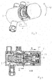
- Fig. 1:
- eine erste Ausführungsform des Thermostatmischventils mit einer abgenommenen Abdeckkappe,
- Fig. 2:
- das Thermostatmischventil mit festgelegter Kappe in einer ersten Ansicht,
- Fig. 3:
- das Thermostatmischventil mit festgelegter Abdeckkappe in einer zweiten Ansicht,
- Fig. 4:
- einen Längsschnitt durch das Thermostatmischventil mit festgelegter Abdeckkappe,
- Fig. 5:
- einen Querschnitt durch das Thermostatmischventil entlang der Linie K-K der
Fig. 4 , - Fig. 6:
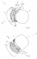
- eine zweite Ausführungsform des Thermostatmischventils in einer ersten Ansicht,
- Fig. 7:
- das Thermostatmischventil in einer zweiten Ansicht und
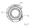
- Fig. 8:
- ein Querschnitt durch das Thermostatmischventil.
- Das Thermostatmischventil 1 umfasst ein Gehäuse 2 mit einem Kaltwassereinlass 19, einem Warmwassereinlass 20 und einem Mischwasserauslass 16. In dem Gehäuse 2 ist eine Mischerkartusche 22 angeordnet, die mit einer Verstelleinheit 3 und einem Konturring 23 über das Gehäuse 2 hervorsteht. Über die Verstelleinheit 3 und den Konturring 23 kann eine Abdeckkappe 4 gestülpt werden, die an dem Gehäuse 2 festgelegt wird.
- Die Verstelleinheit 3 umfasst ein Aufsetzelement 17, welches mittels eines Riegels 18 an einem Drehelement 21 der Mischerkartusche 22 festgelegt ist. Die Ausrichtung des Aufsetzelements 17 zu dem Drehelement 21 kann geändert werden, indem der Riegel 18 gelöst wird und das Aufsetzelement 17 in einer anderen Ausrichtung auf das Drehelement 21 aufgesetzt und durch den Riegel 18 festgelegt wird.
- Auf einer Außenumfangsfläche 9 des Aufsetzelements 17 ist eine in axialer Richtung verlaufende Nut 7 ausgebildet, die mit einer an einer Innenumfangsfläche 10 der Abdeckkappe 4 ausgebildeten Feder 8 korrespondiert (siehe insbesondere
Fig. 2 ). Durch die drehfeste Verbindung zwischen Nut 7 und Feder 8 wird eine Zwangsführung 5 zwischen Abdeckkappe 4 und Verstelleinheit 3 realisiert, so dass die Abdeckkappe 4 nur über die Verstelleinheit 3 gestülpt werden kann, wenn sich die Abdeckkappe 4 in einer durch die Zwangsführung 5 vorgegebene Ausrichtung zu der Verstelleinheit 3 befindet. In einem nur teilweise auf die Verstelleinheit 3 gestülpten Zustand kann somit durch die Drehung der Abdeckkappe 4 das Aufsetzelement 17 und somit auch das Drehelement 21 insbesondere relativ zu dem Gehäuse 2 und dem Konturring 23 gedreht werden. - Zudem ist an einer äußeren Umfangsfläche 12 das Gehäuse 2 an einem der Abdeckkappe 4 zugewandten Ende des Gehäuses 2, welches im aufgesteckten Zustand mit der Abdeckkappe 4 überlappt, eine Ausnehmung 14 ausgebildet, die mit einem Vorsprung 13 an der Abdeckkappe 4 korrespondiert (siehe insbesondere
Fig. 3 und5 ). Durch die Ausnehmung 14 an dem Gehäuse 2 und dem Vorsprung 13 an der Abdeckkappe 4 wird ein Formschluss ausgebildet. Die Abdeckkappe 4 kann daher nur an dem Gehäuse 2 festgelegt werden, wenn die Abdeckkappe 4 entsprechend des Formschlusses 6 zu dem Gehäuse 2 ausgerichtet ist. - Da somit die Abdeckkappe 4 nur in einer durch die Zwangsführung 5 vorgegebenen Ausrichtung über die Verstelleinheit 3 stülpbar ist und in einer durch den Formschluss 6 vorgegebenen Stellung an dem Gehäuse 2 festlegbar ist, kann eine Festlegung der Abdeckkappe 4 an dem Gehäuse 2 nur erfolgen, wenn die Verstelleinheit 3 in einer entsprechenden Stellung ausgerichtet ist. Diese Stellung der Verstelleinheit 3 korrespondiert mit der gewünschten Solltemperatur des Mischwassers.
- Wie insbesondere aus
Fig. 1 zu erkennen ist, ist der Formschluss 5 zwischen Abdeckkappe 4 und Verstelleinheit 3 in Umfangsrichtung 15 versetzt zu dem Formschluss 6 zwischen Abdeckkappe 4 und Gehäuse 2 angeordnet. Alternativ könnten der Formschluss 6 und die Zwangsführung 5 in axialer Richtung fluchtend zueinander angeordnet sein. - Die
Fig. 6 bis 8 zeigen ein weiteres Ausführungsbeispiel des Thermostatmischventils 1, wobei im Folgenden im Wesentlichen auf die Unterschiede zu dem ersten Ausführungsbeispiel eingegangen wird. - Bei diesem Ausführungsbeispiel wird der Formschluss 6 zur drehfesten Festlegung der Verstelleinheit 3 zwischen der Abdeckkappe 4 und der Mischerkartusche 22 gebildet. Die Mischerkartusche 22 weist einen Konturring 23 auf, der im montierten Zustand drehfest in dem Gehäuse 2 angeordnet ist. An dem Konturring 23 sind mehrere Ausnehmungen 14 ausgebildet. Die Abdeckkappe 4 weist zwei Vorsprünge 13 auf, die so angeordnet sind, dass die Abdeckkappe 4 nur in genau einer Ausrichtung vollständig über den Konturring 23 geschoben werden kann. Somit ist sichergestellt, dass die über die Zwangsführung 6 mit der Verstelleinheit 3 verbundene Abdeckkappe 4 nur in genau einer Ausrichtung vollständig von der Abdeckkappe 4 überdeckt werden kann. In dieser Ausrichtung ist die gewünschte Solltemperatur eingestellt.
-
- 1
- Thermostatmischventil
- 2
- Gehäuse
- 3
- Verstelleinheit
- 4
- Abdeckkappe
- 5
- Zwangsführung
- 6
- Formschluss
- 7
- Nut
- 8
- Feder
- 9
- Außenumfangsfläche
- 10
- Innenumfangsfläche
- 11
- Kappenöffnung
- 12
- äußere Umfangsfläche
- 13
- Vorsprung
- 14
- Ausnehmung
- 15
- Umfangsrichtung
- 16
- Mischwasserauslass
- 17
- Aufsetzelement
- 18
- Riegel
- 19
- Kaltwassereinlass
- 20
- Warmwassereinlass
- 21
- Drehelement
- 22
- Mischerkartusche
- 23
- Konturring
Claims (6)
- Sanitäres Thermostatmischventil (1) mit einer in einem Gehäuse (2) angeordneten, ein Thermostatelement aufweisenden Mischerkartusche (22), die eine Solltemperatur des Mischwassers festlegt, wobei die Höhe der Solltemperatur durch eine auf einen Anschlag für das Thermostatelement des Thermostatventils wirkende Verstelleinheit (3) eingestellt werden kann, über die eine Abdeckkappe (4) gestülpt ist, dadurch gekennzeichnet, dass die Abdeckkappe (4) auf der Verstelleinheit (3) drehfest mittels einer Zwangsführung (5) geführt ist und dass die Abdeckkappe ferner drehfest mittels eines Formschlusses (6) an dem Gehäuse (2) oder an der Mischerkartusche (22) festgelegt ist derart, dass die Abdeckkappe nur an dem Gehäuse (2) oder an der Mischerkartusche (22) festlegbar ist, wenn sich die Verstelleinheit (3) in einer durch die Zwangsführung (5) der Abdeckkappe (4) mit der Verstelleinheit (3) und den Formschluss (6) der Abdeckkappe (4) mit dem Gehäuse (2) oder mit der Mischerkartusche (22) vorgegebenen, die Solltemperatur des Mischwassers einstellenden Stellung befindet, wobei die Zwangsführung (5) der Abdeckkappe (4) und der Verstelleinheit (3) durch eine an einer Innenumfangsfläche (10) der Abdeckkappe (4) und einer Außenumfangsfläche (9) der Verstelleinheit (3) in axialer Richtung verlaufende Nut-Feder-Führung (7, 8) ausgebildet ist, so dass sich die Abdeckkappe (4) nur in einer durch die Zwangsführung (5) vorgegebenen Ausrichtung auf die Verstelleinheit (3) aufschieben lässt.
- Thermostatventil (1) nach Anspruch 1, wobei der Formschluss (6) zwischen der Abdeckkappe (4) und dem Gehäuse (2) durch einen im Bereich einer Kappenöffnung (11) der Abdeckkappe (4) und im Bereich einer äußeren Umfangsfläche (12) des Gehäuses (2) angeordneten Eingriff eines Vorsprungs (13) in eine Ausnehmung (14) ausgebildet ist.
- Thermostatventil (1) nach Anspruch 1, wobei der Formschluss (6) zwischen der Abdeckkappe (4) und der Mischerkartusche (22) durch einen Eingriff eines Vorsprungs (13) in eine Ausnehmung (14) ausgebildet ist.
- Thermostatventil (1) nach einem der vorhergehenden Ansprüche, wobei die Zwangsführung (5) der Abdeckkappe (4) mit der Verstelleinheit (3) in Umfangsrichtung (15) versetzt zu dem Formschluss (6) der Abdeckkappe (4) mit dem Gehäuse (2) oder mit der Mischerkartusche (22) angeordnet ist.
- Thermostatventil (1) nach einem der Ansprüche 1 bis 3, wobei die Zwangsführung (5) der Abdeckkappe (4) mit der Verstelleinheit (3) axial fluchtend zu dem Formschluss (6) der Abdeckkappe (4) mit dem Gehäuse (2) oder mit der Mischerkartusche (22) angeordnet ist.
- Thermostatventil (1) nach einem der vorhergehenden Ansprüche, wobei die Verstelleinheit (3) ein auf den Anschlag für das Thermostatelement wirkendes Drehelement (21) und ein auf das Drehelement (21) aufsetzbares Aufsetzelement (17) umfasst, wobei das Aufsetzelement (17) insbesondere mittels eines U-förmigen Riegels (18) in einer veränderbaren Ausrichtung zu dem Drehelement (16) festlegbar ist.
Applications Claiming Priority (1)
| Application Number | Priority Date | Filing Date | Title |
|---|---|---|---|
| DE102015113235 | 2015-08-11 |
Publications (2)
| Publication Number | Publication Date |
|---|---|
| EP3133462A1 true EP3133462A1 (de) | 2017-02-22 |
| EP3133462B1 EP3133462B1 (de) | 2018-10-03 |
Family
ID=56851365
Family Applications (1)
| Application Number | Title | Priority Date | Filing Date |
|---|---|---|---|
| EP16182300.0A Active EP3133462B1 (de) | 2015-08-11 | 2016-08-02 | Thermostatventil mit zwangsführung aufweisender abdeckkappe |
Country Status (3)
| Country | Link |
|---|---|
| EP (1) | EP3133462B1 (de) |
| ES (1) | ES2697407T3 (de) |
| TR (1) | TR201816323T4 (de) |
Cited By (3)
| Publication number | Priority date | Publication date | Assignee | Title |
|---|---|---|---|---|
| EP3540129A1 (de) * | 2018-03-12 | 2019-09-18 | Flühs Drehtechnik GmbH | Sanitärarmatur |
| DE102018213711A1 (de) * | 2018-08-15 | 2020-02-20 | Festo Ag & Co. Kg | Ventil |
| EP4276570A1 (de) | 2022-05-13 | 2023-11-15 | Ideal Standard International NV | Verstelleinheit für eine thermostatkartusche |
Citations (6)
| Publication number | Priority date | Publication date | Assignee | Title |
|---|---|---|---|---|
| EP0745798A2 (de) * | 1995-05-31 | 1996-12-04 | Friedrich Grohe Aktiengesellschaft | Stellgriff einer Sanitärarmatur |
| DE19545587A1 (de) | 1995-12-07 | 1997-06-12 | Grohe Armaturen Friedrich | Stellgriff |
| EP0875703B1 (de) | 1995-01-25 | 2003-06-04 | Ideal-Standard GmbH & Co. OHG | Sanitäre Mischbatterie mit Thermostateinrichtung |
| EP1752695A2 (de) * | 2005-08-11 | 2007-02-14 | Grohe AG | Stellgriff für ein Wasserventil |
| DE102006045540A1 (de) | 2006-09-25 | 2008-04-03 | Grohe Ag | Stellgriff für ein Wasserventil |
| DE102004050996B4 (de) | 2004-10-20 | 2013-07-25 | Hansa Metallwerke Ag | Sanitäres Thermostat-Mischventil |
-
2016
- 2016-08-02 EP EP16182300.0A patent/EP3133462B1/de active Active
- 2016-08-02 TR TR2018/16323T patent/TR201816323T4/tr unknown
- 2016-08-02 ES ES16182300T patent/ES2697407T3/es active Active
Patent Citations (6)
| Publication number | Priority date | Publication date | Assignee | Title |
|---|---|---|---|---|
| EP0875703B1 (de) | 1995-01-25 | 2003-06-04 | Ideal-Standard GmbH & Co. OHG | Sanitäre Mischbatterie mit Thermostateinrichtung |
| EP0745798A2 (de) * | 1995-05-31 | 1996-12-04 | Friedrich Grohe Aktiengesellschaft | Stellgriff einer Sanitärarmatur |
| DE19545587A1 (de) | 1995-12-07 | 1997-06-12 | Grohe Armaturen Friedrich | Stellgriff |
| DE102004050996B4 (de) | 2004-10-20 | 2013-07-25 | Hansa Metallwerke Ag | Sanitäres Thermostat-Mischventil |
| EP1752695A2 (de) * | 2005-08-11 | 2007-02-14 | Grohe AG | Stellgriff für ein Wasserventil |
| DE102006045540A1 (de) | 2006-09-25 | 2008-04-03 | Grohe Ag | Stellgriff für ein Wasserventil |
Cited By (5)
| Publication number | Priority date | Publication date | Assignee | Title |
|---|---|---|---|---|
| EP3540129A1 (de) * | 2018-03-12 | 2019-09-18 | Flühs Drehtechnik GmbH | Sanitärarmatur |
| WO2019174903A1 (de) * | 2018-03-12 | 2019-09-19 | Flühs Drehtechnik GmbH | Sanitärarmatur |
| DE102018213711A1 (de) * | 2018-08-15 | 2020-02-20 | Festo Ag & Co. Kg | Ventil |
| EP4276570A1 (de) | 2022-05-13 | 2023-11-15 | Ideal Standard International NV | Verstelleinheit für eine thermostatkartusche |
| EP4404024A1 (de) | 2022-05-13 | 2024-07-24 | Ideal Standard International NV | Verstelleinheit für eine thermostatkartusche |
Also Published As
| Publication number | Publication date |
|---|---|
| ES2697407T3 (es) | 2019-01-23 |
| TR201816323T4 (tr) | 2018-11-21 |
| EP3133462B1 (de) | 2018-10-03 |
Similar Documents
| Publication | Publication Date | Title |
|---|---|---|
| DE2528717C2 (de) | Eingriffwasserhahn | |
| DE69326703T2 (de) | Einhebelmischventilkartusche für heisses und kaltes Wasser | |
| EP3561351B1 (de) | Misch- und absperrventilvorrichtung sowie sanitäre misch- und absperrarmatur | |
| DE102009031393B4 (de) | Ratschenschlüssel | |
| DE112014004621B4 (de) | Einhebel-Thermostatkartusche | |
| EP3133462B1 (de) | Thermostatventil mit zwangsführung aufweisender abdeckkappe | |
| EP1903268A2 (de) | Stellgriff für ein Wasserventil | |
| EP3021023B1 (de) | Sanitärarmatur mit versetzt angeordneter bedienungselementschwenkachse | |
| EP3486407B1 (de) | Drückerelement und fenstergriffgarnitur | |
| EP3015946A2 (de) | Haushaltsgerät, insbesondere durchlauferhitzer | |
| EP3754680B1 (de) | Schaltervorrichtung für ein gargerät mit einem durch eine tür verschliessbaren garraum und gargerät | |
| EP1970609B1 (de) | Ventilantrieb | |
| EP4493846B1 (de) | Ventil | |
| EP2980673B1 (de) | Haushaltsgerät | |
| DE19910224C1 (de) | Thermostatkopf für Heizungsventile | |
| EP2775368B1 (de) | Überlasteinheit für ein Thermostatventil | |
| EP3358091B1 (de) | Mischkartusche mit auf die lagerhülse aufsteckbarer anschlaghülse | |
| DE2627923A1 (de) | Mischarmatur fuer kalt- und warmwasser | |
| DE2050025B2 (de) | Eingriff Mischbatterie | |
| EP4276570B1 (de) | Verstelleinheit für eine thermostatkartusche | |
| EP4628769A1 (de) | Bediengriffvorrichtung für ein thermostatventil und wandeinbauvorrichtung | |
| DE1163468B (de) | Vorrichtung zur Betaetigung eines elektrischen Schalters und eines Thermostaten | |
| EP2648062A2 (de) | Drehknebel | |
| DE1553464C (de) | Einrichtung zum Wechseln des Einstell geheimnisses in einem Permutationsschloß | |
| DE10102479A1 (de) | Kartusche mit Einrichtung zur Reduzierung des Durchflusses |
Legal Events
| Date | Code | Title | Description |
|---|---|---|---|
| PUAI | Public reference made under article 153(3) epc to a published international application that has entered the european phase |
Free format text: ORIGINAL CODE: 0009012 |
|
| STAA | Information on the status of an ep patent application or granted ep patent |
Free format text: STATUS: THE APPLICATION HAS BEEN PUBLISHED |
|
| AK | Designated contracting states |
Kind code of ref document: A1 Designated state(s): AL AT BE BG CH CY CZ DE DK EE ES FI FR GB GR HR HU IE IS IT LI LT LU LV MC MK MT NL NO PL PT RO RS SE SI SK SM TR |
|
| AX | Request for extension of the european patent |
Extension state: BA ME |
|
| STAA | Information on the status of an ep patent application or granted ep patent |
Free format text: STATUS: REQUEST FOR EXAMINATION WAS MADE |
|
| 17P | Request for examination filed |
Effective date: 20170719 |
|
| RBV | Designated contracting states (corrected) |
Designated state(s): AL AT BE BG CH CY CZ DE DK EE ES FI FR GB GR HR HU IE IS IT LI LT LU LV MC MK MT NL NO PL PT RO RS SE SI SK SM TR |
|
| GRAP | Despatch of communication of intention to grant a patent |
Free format text: ORIGINAL CODE: EPIDOSNIGR1 |
|
| STAA | Information on the status of an ep patent application or granted ep patent |
Free format text: STATUS: GRANT OF PATENT IS INTENDED |
|
| RIC1 | Information provided on ipc code assigned before grant |
Ipc: G05D 23/13 20060101AFI20180308BHEP |
|
| INTG | Intention to grant announced |
Effective date: 20180329 |
|
| GRAS | Grant fee paid |
Free format text: ORIGINAL CODE: EPIDOSNIGR3 |
|
| GRAA | (expected) grant |
Free format text: ORIGINAL CODE: 0009210 |
|
| STAA | Information on the status of an ep patent application or granted ep patent |
Free format text: STATUS: THE PATENT HAS BEEN GRANTED |
|
| AK | Designated contracting states |
Kind code of ref document: B1 Designated state(s): AL AT BE BG CH CY CZ DE DK EE ES FI FR GB GR HR HU IE IS IT LI LT LU LV MC MK MT NL NO PL PT RO RS SE SI SK SM TR |
|
| REG | Reference to a national code |
Ref country code: GB Ref legal event code: FG4D Free format text: NOT ENGLISH |
|
| REG | Reference to a national code |
Ref country code: CH Ref legal event code: EP Ref country code: AT Ref legal event code: REF Ref document number: 1049287 Country of ref document: AT Kind code of ref document: T Effective date: 20181015 |
|
| REG | Reference to a national code |
Ref country code: DE Ref legal event code: R096 Ref document number: 502016002140 Country of ref document: DE Ref country code: IE Ref legal event code: FG4D Free format text: LANGUAGE OF EP DOCUMENT: GERMAN |
|
| REG | Reference to a national code |
Ref country code: ES Ref legal event code: FG2A Ref document number: 2697407 Country of ref document: ES Kind code of ref document: T3 Effective date: 20190123 |
|
| REG | Reference to a national code |
Ref country code: NL Ref legal event code: MP Effective date: 20181003 |
|
| REG | Reference to a national code |
Ref country code: LT Ref legal event code: MG4D |
|
| PG25 | Lapsed in a contracting state [announced via postgrant information from national office to epo] |
Ref country code: NL Free format text: LAPSE BECAUSE OF FAILURE TO SUBMIT A TRANSLATION OF THE DESCRIPTION OR TO PAY THE FEE WITHIN THE PRESCRIBED TIME-LIMIT Effective date: 20181003 |
|
| PG25 | Lapsed in a contracting state [announced via postgrant information from national office to epo] |
Ref country code: CZ Free format text: LAPSE BECAUSE OF FAILURE TO SUBMIT A TRANSLATION OF THE DESCRIPTION OR TO PAY THE FEE WITHIN THE PRESCRIBED TIME-LIMIT Effective date: 20181003 Ref country code: LT Free format text: LAPSE BECAUSE OF FAILURE TO SUBMIT A TRANSLATION OF THE DESCRIPTION OR TO PAY THE FEE WITHIN THE PRESCRIBED TIME-LIMIT Effective date: 20181003 Ref country code: BG Free format text: LAPSE BECAUSE OF FAILURE TO SUBMIT A TRANSLATION OF THE DESCRIPTION OR TO PAY THE FEE WITHIN THE PRESCRIBED TIME-LIMIT Effective date: 20190103 Ref country code: IS Free format text: LAPSE BECAUSE OF FAILURE TO SUBMIT A TRANSLATION OF THE DESCRIPTION OR TO PAY THE FEE WITHIN THE PRESCRIBED TIME-LIMIT Effective date: 20190203 Ref country code: PL Free format text: LAPSE BECAUSE OF FAILURE TO SUBMIT A TRANSLATION OF THE DESCRIPTION OR TO PAY THE FEE WITHIN THE PRESCRIBED TIME-LIMIT Effective date: 20181003 Ref country code: NO Free format text: LAPSE BECAUSE OF FAILURE TO SUBMIT A TRANSLATION OF THE DESCRIPTION OR TO PAY THE FEE WITHIN THE PRESCRIBED TIME-LIMIT Effective date: 20190103 Ref country code: HR Free format text: LAPSE BECAUSE OF FAILURE TO SUBMIT A TRANSLATION OF THE DESCRIPTION OR TO PAY THE FEE WITHIN THE PRESCRIBED TIME-LIMIT Effective date: 20181003 Ref country code: LV Free format text: LAPSE BECAUSE OF FAILURE TO SUBMIT A TRANSLATION OF THE DESCRIPTION OR TO PAY THE FEE WITHIN THE PRESCRIBED TIME-LIMIT Effective date: 20181003 Ref country code: FI Free format text: LAPSE BECAUSE OF FAILURE TO SUBMIT A TRANSLATION OF THE DESCRIPTION OR TO PAY THE FEE WITHIN THE PRESCRIBED TIME-LIMIT Effective date: 20181003 |
|
| PG25 | Lapsed in a contracting state [announced via postgrant information from national office to epo] |
Ref country code: SE Free format text: LAPSE BECAUSE OF FAILURE TO SUBMIT A TRANSLATION OF THE DESCRIPTION OR TO PAY THE FEE WITHIN THE PRESCRIBED TIME-LIMIT Effective date: 20181003 Ref country code: GR Free format text: LAPSE BECAUSE OF FAILURE TO SUBMIT A TRANSLATION OF THE DESCRIPTION OR TO PAY THE FEE WITHIN THE PRESCRIBED TIME-LIMIT Effective date: 20190104 Ref country code: AL Free format text: LAPSE BECAUSE OF FAILURE TO SUBMIT A TRANSLATION OF THE DESCRIPTION OR TO PAY THE FEE WITHIN THE PRESCRIBED TIME-LIMIT Effective date: 20181003 Ref country code: RS Free format text: LAPSE BECAUSE OF FAILURE TO SUBMIT A TRANSLATION OF THE DESCRIPTION OR TO PAY THE FEE WITHIN THE PRESCRIBED TIME-LIMIT Effective date: 20181003 Ref country code: PT Free format text: LAPSE BECAUSE OF FAILURE TO SUBMIT A TRANSLATION OF THE DESCRIPTION OR TO PAY THE FEE WITHIN THE PRESCRIBED TIME-LIMIT Effective date: 20190203 |
|
| REG | Reference to a national code |
Ref country code: DE Ref legal event code: R097 Ref document number: 502016002140 Country of ref document: DE |
|
| PG25 | Lapsed in a contracting state [announced via postgrant information from national office to epo] |
Ref country code: DK Free format text: LAPSE BECAUSE OF FAILURE TO SUBMIT A TRANSLATION OF THE DESCRIPTION OR TO PAY THE FEE WITHIN THE PRESCRIBED TIME-LIMIT Effective date: 20181003 |
|
| PLBE | No opposition filed within time limit |
Free format text: ORIGINAL CODE: 0009261 |
|
| STAA | Information on the status of an ep patent application or granted ep patent |
Free format text: STATUS: NO OPPOSITION FILED WITHIN TIME LIMIT |
|
| PG25 | Lapsed in a contracting state [announced via postgrant information from national office to epo] |
Ref country code: SK Free format text: LAPSE BECAUSE OF FAILURE TO SUBMIT A TRANSLATION OF THE DESCRIPTION OR TO PAY THE FEE WITHIN THE PRESCRIBED TIME-LIMIT Effective date: 20181003 Ref country code: RO Free format text: LAPSE BECAUSE OF FAILURE TO SUBMIT A TRANSLATION OF THE DESCRIPTION OR TO PAY THE FEE WITHIN THE PRESCRIBED TIME-LIMIT Effective date: 20181003 Ref country code: EE Free format text: LAPSE BECAUSE OF FAILURE TO SUBMIT A TRANSLATION OF THE DESCRIPTION OR TO PAY THE FEE WITHIN THE PRESCRIBED TIME-LIMIT Effective date: 20181003 Ref country code: SM Free format text: LAPSE BECAUSE OF FAILURE TO SUBMIT A TRANSLATION OF THE DESCRIPTION OR TO PAY THE FEE WITHIN THE PRESCRIBED TIME-LIMIT Effective date: 20181003 |
|
| 26N | No opposition filed |
Effective date: 20190704 |
|
| PG25 | Lapsed in a contracting state [announced via postgrant information from national office to epo] |
Ref country code: SI Free format text: LAPSE BECAUSE OF FAILURE TO SUBMIT A TRANSLATION OF THE DESCRIPTION OR TO PAY THE FEE WITHIN THE PRESCRIBED TIME-LIMIT Effective date: 20181003 |
|
| PG25 | Lapsed in a contracting state [announced via postgrant information from national office to epo] |
Ref country code: LU Free format text: LAPSE BECAUSE OF NON-PAYMENT OF DUE FEES Effective date: 20190802 Ref country code: MC Free format text: LAPSE BECAUSE OF FAILURE TO SUBMIT A TRANSLATION OF THE DESCRIPTION OR TO PAY THE FEE WITHIN THE PRESCRIBED TIME-LIMIT Effective date: 20181003 Ref country code: LI Free format text: LAPSE BECAUSE OF NON-PAYMENT OF DUE FEES Effective date: 20190831 Ref country code: CH Free format text: LAPSE BECAUSE OF NON-PAYMENT OF DUE FEES Effective date: 20190831 |
|
| REG | Reference to a national code |
Ref country code: BE Ref legal event code: MM Effective date: 20190831 |
|
| PG25 | Lapsed in a contracting state [announced via postgrant information from national office to epo] |
Ref country code: IE Free format text: LAPSE BECAUSE OF NON-PAYMENT OF DUE FEES Effective date: 20190802 |
|
| PG25 | Lapsed in a contracting state [announced via postgrant information from national office to epo] |
Ref country code: BE Free format text: LAPSE BECAUSE OF NON-PAYMENT OF DUE FEES Effective date: 20190831 |
|
| PG25 | Lapsed in a contracting state [announced via postgrant information from national office to epo] |
Ref country code: CY Free format text: LAPSE BECAUSE OF FAILURE TO SUBMIT A TRANSLATION OF THE DESCRIPTION OR TO PAY THE FEE WITHIN THE PRESCRIBED TIME-LIMIT Effective date: 20181003 |
|
| PG25 | Lapsed in a contracting state [announced via postgrant information from national office to epo] |
Ref country code: MT Free format text: LAPSE BECAUSE OF FAILURE TO SUBMIT A TRANSLATION OF THE DESCRIPTION OR TO PAY THE FEE WITHIN THE PRESCRIBED TIME-LIMIT Effective date: 20181003 Ref country code: HU Free format text: LAPSE BECAUSE OF FAILURE TO SUBMIT A TRANSLATION OF THE DESCRIPTION OR TO PAY THE FEE WITHIN THE PRESCRIBED TIME-LIMIT; INVALID AB INITIO Effective date: 20160802 |
|
| PG25 | Lapsed in a contracting state [announced via postgrant information from national office to epo] |
Ref country code: MK Free format text: LAPSE BECAUSE OF FAILURE TO SUBMIT A TRANSLATION OF THE DESCRIPTION OR TO PAY THE FEE WITHIN THE PRESCRIBED TIME-LIMIT Effective date: 20181003 |
|
| PGFP | Annual fee paid to national office [announced via postgrant information from national office to epo] |
Ref country code: ES Payment date: 20250901 Year of fee payment: 10 |
|
| PGFP | Annual fee paid to national office [announced via postgrant information from national office to epo] |
Ref country code: DE Payment date: 20250827 Year of fee payment: 10 |
|
| PGFP | Annual fee paid to national office [announced via postgrant information from national office to epo] |
Ref country code: IT Payment date: 20250820 Year of fee payment: 10 Ref country code: TR Payment date: 20250721 Year of fee payment: 10 |
|
| PGFP | Annual fee paid to national office [announced via postgrant information from national office to epo] |
Ref country code: GB Payment date: 20250827 Year of fee payment: 10 |
|
| PGFP | Annual fee paid to national office [announced via postgrant information from national office to epo] |
Ref country code: FR Payment date: 20250825 Year of fee payment: 10 Ref country code: AT Payment date: 20250827 Year of fee payment: 10 |
|
| REG | Reference to a national code |
Ref country code: DE Ref legal event code: R082 Ref document number: 502016002140 Country of ref document: DE Representative=s name: DIPAS PATENTANWALTS GMBH, DE |