EP3133449B1 - Überwachungsschaltung und elektronische vorrichtung - Google Patents
Überwachungsschaltung und elektronische vorrichtung Download PDFInfo
- Publication number
- EP3133449B1 EP3133449B1 EP14891994.7A EP14891994A EP3133449B1 EP 3133449 B1 EP3133449 B1 EP 3133449B1 EP 14891994 A EP14891994 A EP 14891994A EP 3133449 B1 EP3133449 B1 EP 3133449B1
- Authority
- EP
- European Patent Office
- Prior art keywords
- resistor
- circuit
- dry contact
- switch circuit
- control
- Prior art date
- Legal status (The legal status is an assumption and is not a legal conclusion. Google has not performed a legal analysis and makes no representation as to the accuracy of the status listed.)
- Active
Links
Images

Classifications
-
- H—ELECTRICITY
- H02—GENERATION; CONVERSION OR DISTRIBUTION OF ELECTRIC POWER
- H02H—EMERGENCY PROTECTIVE CIRCUIT ARRANGEMENTS
- H02H9/00—Emergency protective circuit arrangements for limiting excess current or voltage without disconnection
- H02H9/04—Emergency protective circuit arrangements for limiting excess current or voltage without disconnection responsive to excess voltage
- H02H9/044—Physical layout, materials not provided for elsewhere
-
- G—PHYSICS
- G05—CONTROLLING; REGULATING
- G05B—CONTROL OR REGULATING SYSTEMS IN GENERAL; FUNCTIONAL ELEMENTS OF SUCH SYSTEMS; MONITORING OR TESTING ARRANGEMENTS FOR SUCH SYSTEMS OR ELEMENTS
- G05B19/00—Program-control systems
- G05B19/02—Program-control systems electric
- G05B19/04—Program control other than numerical control, i.e. in sequence controllers or logic controllers
- G05B19/042—Program control other than numerical control, i.e. in sequence controllers or logic controllers using digital processors
-
- G—PHYSICS
- G01—MEASURING; TESTING
- G01R—MEASURING ELECTRIC VARIABLES; MEASURING MAGNETIC VARIABLES
- G01R31/00—Arrangements for testing electric properties; Arrangements for locating electric faults; Arrangements for electrical testing characterised by what is being tested not provided for elsewhere
- G01R31/327—Testing of circuit interrupters, switches or circuit-breakers
- G01R31/3277—Testing of circuit interrupters, switches or circuit-breakers of low voltage devices, e.g. domestic or industrial devices, such as motor protections, relays, rotation switches
- G01R31/3278—Testing of circuit interrupters, switches or circuit-breakers of low voltage devices, e.g. domestic or industrial devices, such as motor protections, relays, rotation switches of relays, solenoids or reed switches
-
- G—PHYSICS
- G05—CONTROLLING; REGULATING
- G05B—CONTROL OR REGULATING SYSTEMS IN GENERAL; FUNCTIONAL ELEMENTS OF SUCH SYSTEMS; MONITORING OR TESTING ARRANGEMENTS FOR SUCH SYSTEMS OR ELEMENTS
- G05B19/00—Program-control systems
- G05B19/02—Program-control systems electric
- G05B19/04—Program control other than numerical control, i.e. in sequence controllers or logic controllers
- G05B19/048—Monitoring; Safety
-
- H—ELECTRICITY
- H04—ELECTRIC COMMUNICATION TECHNIQUE
- H04L—TRANSMISSION OF DIGITAL INFORMATION, e.g. TELEGRAPHIC COMMUNICATION
- H04L43/00—Arrangements for monitoring or testing data switching networks
Definitions
- the present invention relates to the circuit field, and in particular, to a monitoring circuit and an electronic device.
- a dry contact monitoring manner is generally used in a station power monitoring system. Dry contacts are classified into an input dry contact and an output dry contact.
- the input dry contact for example, a switch or a button, is used to receive an external Boolean signal, and the output dry contact is used to implement alarm output, association control, or the like.
- an input dry contact monitoring circuit and an output dry contact monitoring circuit are mutually independent. That is, the input dry contact monitoring circuit includes: a configuration interface, a protection circuit, and a detection circuit, where the detection circuit is configured to detect a status of a signal received by an input dry contact connected to the configuration interface; the output dry contact monitoring circuit includes: a configuration interface, a protection circuit, a relay, a control circuit, and a detection circuit, where the detection circuit is configured to detect a working status of the relay, and further determine a working status of an output dry contact connected to the configuration interface.
- WO 2007/025203A2 refers to a self-testing circuit interrupting device, which provides uninterrupted power to a load during a complete electronic and electromechanical components self test to allow autonomous periodic automated self testing without damaging or resetting connected load equipment.
- the input dry contact monitoring circuit and the output dry contact monitoring circuit use different configuration interfaces.
- the configuration interface in the input dry contact monitoring circuit cannot be configured as an output dry contact.
- the configuration interface in the output dry contact monitoring circuit cannot be configured as an input dry contact.
- Embodiments of the present invention provide a monitoring circuit and an electronic device, which are used to improve configurability of a system.
- an embodiment of the present invention provides a monitoring circuit, including: a configuration interface, a control circuit, a detection circuit, a direct current voltage source, a switch circuit, and a first resistor, where a first end of the configuration interface is separately connected to the direct current voltage source and an input end of the switch circuit, a second end of the configuration interface is separately connected to a first end of the first resistor and an output end of the switch circuit, a control end of the switch circuit is connected to the control circuit, a second end of the first resistor is grounded, and the detection circuit is connected to the first end of the first resistor; the configuration interface is furthermore only configured to connect the monitoring circuit to an external dry contact, where the dry contact includes an input dry contact being a switch or button or an output dry contact being an alarm; the control circuit is configured to control closing or opening of the switch circuit; and the detection circuit is configured to detect a voltage between two ends of the first resistor.
- the circuit further includes a protection circuit, where the protection circuit includes: a discharge tube, a second resistor, a third resistor, a fourth resistor, and a fifth resistor; the first end of the configuration interface is connected to the input end of the switch circuit by using the second resistor, a first end of the second resistor is connected to the first end of the configuration interface, a second end of the second resistor is connected to the input end of the switch circuit, the second end of the configuration interface is connected to the output end of the switch circuit by using the third resistor, a first end of the third resistor is connected to the second end of the configuration interface, a second end of the third resistor is connected to the output end of the switch circuit, a first end of the discharge tube is connected to the first end of the second resistor, a second end of the discharge tube is connected to the first end of the third resistor, the first end of the configuration interface is connected to
- the discharge tube includes a gas discharge tube.
- the switch circuit includes a relay.
- the detection circuit includes an analog-to-digital conversion circuit and a microprocessing unit.
- control circuit includes the switch circuit driving unit.
- an embodiment of the present invention provides an electronic device, including the monitoring circuit described in the foregoing embodiment.
- the embodiments of the present invention provide a monitoring circuit and an electronic device, where the monitoring circuit includes: a configuration interface, a control circuit, a detection circuit, a direct current voltage source, a switch circuit, and a first resistor.
- the configuration interface is configured to connect to a dry contact
- the control circuit is configured to control closing or opening of the switch circuit
- the detection circuit is configured to detect a voltage between two ends of the first resistor.
- the control circuit controls the switch circuit to be opened, and the detection circuit determines an action status of the input dry contact according to a value of the detected voltage between the two ends of the first resistor; when the configuration interface is connected to an output dry contact, the control circuit controls closing or opening of the switch circuit according to a preset rule, and the detection circuit determines an action status of the output dry contact according to a value of the detected voltage between the two ends of the first resistor. In this way, an objective of detecting a dry contact is achieved.
- an input dry contact may be configured as an output dry contact; when an input dry contact configured in the system cannot satisfy a user's use requirement, an output dry contact may be configured as an input dry contact. Therefore, configurability of the system is improved.
- An embodiment of the present invention provides a schematic diagram of a monitoring circuit.
- the monitoring circuit includes: a configuration interface 101, a control circuit 102, a detection circuit 103, a direct current voltage source 104, a switch circuit 105, and a first resistor 106.
- the switch circuit 105 includes: an input end 1051, an output end 1052, and a control end 1053.
- a first end of the configuration interface 101 is separately connected to the direct current voltage source 104 and the input end 1051 of the switch circuit 105, a second end of the configuration interface 101 is separately connected to a first end of the first resistor 106 and the output end 1052 of the switch circuit 105, the control end 1053 of the switch circuit 105 is connected to the control circuit 102, a second end of the first resistor 106 is grounded, and the detection circuit 103 is connected to the first end of the first resistor 106.
- the configuration interface 101 is configured to connect to a dry contact.
- the dry contact includes an input dry contact or an output dry contact.
- a user may configure the configuration interface 101 according to a requirement.
- an input dry contact is connected to the configuration interface 101; when the system needs to implement alarm output or other output control, an output dry contact is connected to the configuration interface 101.
- the input dry contact may be a button, a switch, or the like; the output dry contact may be an alarm or the like, which is not limited in the present invention.
- the control circuit 102 is configured to control closing or opening of the switch circuit 105.
- the control circuit 102 includes the switch circuit driving unit.
- the detection circuit 103 is configured to detect a voltage between two ends of the first resistor 106.
- the detection circuit 103 includes an analog-to-digital conversion circuit and a microprocessing unit.
- the detection circuit 103 when detecting the voltage between the two ends of the first resistor 106, the detection circuit 103 first converts a detected analog voltage between the two ends of the first resistor 106 into a digital voltage by using the analog-to-digital conversion circuit, and inputs the digital voltage into the microprocessing unit, so that the microprocessing unit determines a working status of an input dry contact or an output dry contact according to a value of the digital voltage.
- the detection circuit 103 may further include a circuit of another functional module, for example, a filter circuit.
- control circuit 102 is specifically configured to control closing or opening of the switch circuit 105 according to a preset rule when the configuration interface 101 is connected to an output dry contact.
- the detection circuit 103 is further configured to determine a working status of the output dry contact according to the detected voltage between the two ends of the first resistor 106.
- the control circuit 102 determines, according to code configured by the user, that the configuration interface 101 is connected to an output dry contact, and therefore controls closing or opening of the switch circuit 105 according to the rule preset in the system.
- the control end 1053 of the switch circuit 105 is triggered to be closed, so that the input end 1051 and the output end 1052 that are of the switch circuit 105 are connected, so as to provide a loop to the action of the output dry contact, so that the output dry contact performs the action;
- the control end 1053 of the switch circuit 105 is controlled to be in an open state, and the input end 1051 and the output end 1052 that are of the switch circuit 105 are disconnected. Therefore, a loop cannot be formed and the output dry contact cannot perform the action.
- the detection circuit 103 detects an analog voltage between the two ends of the first resistor 106, converts the detected analog voltage between the two ends of the first resistor 106 into a digital voltage by using the analog-to-digital conversion circuit, and inputs the digital voltage into the microprocessing unit; the microprocessing unit determines that the digital voltage is greater than zero, and therefore determines that the output dry contact performs an action.
- the detection circuit 103 detects a voltage between the two ends of the first resistor 106, converts a detected analog voltage between the two ends of the first resistor 106 into a digital voltage by using the analog-to-digital conversion circuit, and inputs the digital voltage into the microprocessing unit; the microprocessing unit determines that the digital voltage is zero, and therefore determines that the output dry contact does not perform an action. In this way, an objective of detecting the output dry contact is achieved.
- the control circuit 102 is specifically configured to control, when the configuration interface 101 is connected to an input dry contact, the switch circuit 105 to be opened.
- the detection circuit 103 is further configured to determine a working status of the input dry contact according to the detected voltage between the two ends of the first resistor 106.
- the control circuit 102 determines, according to code configured by the user, that the configuration interface 101 is connected to an input dry contact, so as to control the switch circuit 105 in an open state.
- the input dry contact is closed, the first end of the configuration interface 101 and the second end of the configuration interface 101 are connected, so that the direct current voltage source 104, the input dry contact, and the first resistor 106 form a loop.
- a particular voltage is generated between the two ends of the first resistor 106, so that the detection circuit 103 can detect that the voltage between the two ends of the first resistor 106 is greater than zero, and determine that the input dry contact is in a closed state.
- the first end of the configuration interface 101 disconnects from the second end of the configuration interface 101.
- a circuit formed by the direct current voltage source 104, the input dry contact, and the first resistor 106 does not form a loop, and there is no voltage between the two ends of the first resistor 106, so that the detection circuit 103 detects that the voltage between the two ends of the first resistor 106 is zero, and determines that the input dry contact is in an open state and does not perform an action. In this way, an objective of detecting the input dry contact is achieved.
- the monitoring circuit further includes a protection circuit 107.
- the protection circuit 107 includes: a discharge tube 1071, a second resistor 1072, a third resistor 1073, a fourth resistor 1074, and a fifth resistor 1075.
- the first end of the configuration interface 101 is connected to the input end 1051 of the switch circuit 105 by using the second resistor 1072, a first end of the second resistor 1072 is connected to the first end of the configuration interface 101, a second end of the second resistor 1072 is connected to the input end 1051 of the switch circuit 105, the second end of the configuration interface 101 is connected to the output end 1052 of the switch circuit 105 by using the third resistor 1073, a first end of the third resistor 1073 is connected to the second end of the configuration interface 101, a second end of the third resistor 1073 is connected to the output end 1052 of the switch circuit 105, a first end of the discharge tube 1071 is connected to the first end of the second resistor 1072, a second end of the discharge tube 1071 is connected to the first end of the third resistor 1073, the first end of the configuration interface 101 is connected to the direct current voltage source 104 by using the fourth resistor 1074, a first end of the fourth resistor 1074 is connected to the direct current voltage source
- the discharge tube 1071 includes a gas discharge tube.
- discharge tube 1071 may also be another discharge tube, for example, a semi-conductor discharge tube, which is not limited in the present invention.
- the protection circuit 107 is configured to bleed off an overcurrent generated by an overvoltage received by the configuration interface 101.
- the overvoltage can conduct the discharge tube 1071 in the protection 107, so that the discharge tube 1071 bleeds off the overcurrent generated by the overvoltage, and clamps a voltage to a voltage value.
- the voltage value further produces impact on a subsequent circuit; therefore, the second resistor 1072, the third resistor 1073, the fourth resistor 1074, and the fifth resistor 1075 are used in the present invention to perform voltage division on the overvoltage, so as to reduce impact on the subsequent circuit exerted by a voltage obtained after the second resistor 1072, the third resistor 1073, the fourth resistor 1074, and the fifth resistor 1075 perform voltage division, which provides further protection for the subsequent circuit.
- first resistor 106, the second resistor 1072, and the third resistor 1073 may all be a high-resistance resistor, or multiple resistors may be connected in series to form one high-resistance resistor.
- the fourth resistor 1074 and the fifth resistor 1075 may both be a low-resistance resistor, or multiple resistors may be connected in parallel to form one low-resistance resistor.
- the switch circuit 105 includes a relay.
- a moving contact of the relay is the input end 1051 of the switch circuit 105
- a coil of the relay is the control end 1053 of the switch circuit 105
- a normally open contact of the relay is the output end 1052 of the switch circuit 105.
- the switch circuit 105 may also be a circuit that is formed by another component and has a switch function, for example, the switch circuit is formed by using a transistor or a field effect transistor, which is not limited in the present invention.
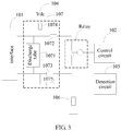
- FIG. 3 is a schematic diagram of an instance of a monitoring circuit according to an embodiment of the present invention.
- the monitoring circuit includes: a configuration interface 101, a control circuit 102, a detection circuit 103, a direct current voltage source 104, a relay, a first resistor 106, and a protection circuit 107.
- a specific working principle is as follows: When the configuration interface 101 is connected to an input dry contact, the control circuit 102 does not provide a current to a coil of the relay, so that the coil of the relay cannot generate induced electromotive force, that is, a moving contact of the relay cannot perform an action; therefore, the relay has no function.
- the input dry contact is closed, a first end of the configuration interface 101 and a second end of the configuration interface 101 are connected, so that the direct current voltage source 104, the input dry contact, a fifth resistor 1075, and the first resistor 106 form a loop.
- a particular voltage is generated between two ends of the first resistor 106, so that the detection circuit 103 can detect that the voltage between the two ends of the first resistor 106 is greater than zero, and determine that the input dry contact is in a closed state.
- the first end of the configuration interface 101 disconnects from the second end of the configuration interface 101.
- a circuit formed by the direct current voltage source 104, the input dry contact, the fifth resistor 1075, and the first resistor 106 does not have a loop, and there is no voltage between the two ends of the first resistor 106, so that the detection circuit 103 detects that the voltage between the two ends of the first resistor 106 is zero, and determines that the input dry contact is in an open state and does not perform an action. In this way, an objective of detecting the input dry contact is achieved.
- the control circuit 102 When the configuration interface 101 is connected to an output dry contact, and an action of the output dry contact is required, the control circuit 102 provides a current to the coil of the relay, so that the coil of the relay generates induced electromotive force; the moving contact and a normally open contact that are of the relay are closed, so that the direct current voltage source 104, a fourth resistor 1074, a second resistor 1072, the relay, a third resistor 1073, the fifth resistor 1075, and the first resistor 106 form a loop, so as to make the output dry contact work.
- the detection circuit 103 may determine a working status of the output dry contact by detecting a voltage between the two ends of the first resistor 106.
- the control circuit 102 does not provide a current to the coil of the relay, so that the coil of the relay cannot generate induced electromotive force, that is, the moving contact of the relay cannot perform an action, and the moving contact and the normally open contact that are of the relay are disconnected, so that the output dry contact cannot perform an action.
- the direct current voltage source 104, the fourth resistor 1074, the second resistor 1072, the relay, the third resistor 1073, the fifth resistor 1075, and the first resistor 106 cannot form a loop.
- the detection circuit 103 detects that the voltage between the two ends of the first resistor 106 is zero, and therefore may determine that the output dry contact does not perform an action.
- the monitoring circuit in the embodiments of the present invention may adopt the following connection:
- the first end of the configuration interface 101 is separately connected to a first end of the first resistor 106 and an input end 1051 of the switch circuit 105, the second end of the configuration interface 101 is separately connected to the direct current voltage source 104 and an output end 1052 of the switch circuit 105, a control end 1053 of the switch circuit 105 is connected to the control circuit 102, a second end of the first resistor 106 is grounded, and the detection circuit 103 is connected to the first end of the first resistor 106.
- connection manner of the protection circuit 107 is similar to the connection manner in the foregoing embodiment, and details are not described herein again.
- This embodiment of the present invention provides a monitoring circuit, which includes a configuration interface, a control circuit, a detection circuit, a direct current voltage source, a switch circuit, and a first resistor.
- the configuration interface is configured to connect to a dry contact
- the control circuit is configured to control closing or opening of the switch circuit
- the detection circuit is configured to detect a voltage between two ends of the first resistor.
- the control circuit controls the switch circuit to be opened, and the detection circuit determines an action status of the input dry contact according to the detected voltage between the two ends of the first resistor; when the configuration interface is connected to an output dry contact, the control circuit controls closing or opening of the switch circuit according to a preset rule, and the detection circuit determines an action status of the output dry contact according to a value of the detected voltage between the two ends of the first resistor. In this way, an objective of detecting a dry contact is achieved.
- an input dry contact may be configured as an output dry contact; when an input dry contact configured in the system cannot satisfy a user's use requirement, an output dry contact may be configured as an input dry contact. Therefore, configurability of the system is improved.
- An embodiment of the present invention provides an electronic device, where the electronic device includes the monitoring circuit described in the foregoing embodiments.
- This embodiment of the present invention provides an electronic device, which includes a monitoring circuit, and the monitoring circuit includes: a configuration interface, a control circuit, a detection circuit, a direct current voltage source, a switch circuit, and a first resistor.
- the configuration interface is configured to connect to a dry contact
- the control circuit is configured to control closing or opening of the switch circuit
- the detection circuit is configured to detect a voltage between two ends of the first resistor.
- the control circuit controls the switch circuit to be opened, and the detection circuit determines an action status of the input dry contact according to a value of the detected voltage between the two ends of the first resistor; when the configuration interface is connected to an output dry contact, the control circuit controls closing or opening of the switch circuit according to a preset rule, and the detection circuit determines an action status of the output dry contact according to a value of the detected voltage between the two ends of the first resistor. In this way, an objective of detecting a dry contact is achieved.
- an input dry contact may be configured as an output dry contact; when an input dry contact configured in the system cannot satisfy a user's use requirement, an output dry contact may be configured as an input dry contact. Therefore, configurability of the system is improved.
- the present invention uses only one protection circuit, which reduces a circuit cost.
- the disclosed system, apparatus, and method may be implemented in other manners.
- the described apparatus embodiment is merely exemplary.
- the unit division is merely logical function division and may be other division in actual implementation.
- a plurality of units or components may be combined or integrated into another system, or some features may be ignored or not performed.
- the displayed or discussed mutual couplings or direct couplings or communication connections may be implemented by using some interfaces.
- the indirect couplings or communication connections between the apparatuses or units may be implemented in electronic, mechanical, or other forms.
- the units described as separate parts may or may not be physically separate, and parts displayed as units may or may not be physical units, may be located in one position, or may be distributed on a plurality of network units. Some or all of the units may be selected according to actual needs to achieve the objectives of the solutions of the embodiments.
- functional units in the embodiments of the present invention may be integrated into one processing unit, or each of the units may exist alone physically, or two or more units are integrated into one unit.
- the integrated unit may be implemented in a form of hardware, or may be implemented in a form of hardware in addition to a software functional unit.
- the integrated unit may be stored in a computer-readable storage medium.
- the software functional unit is stored in a storage medium and includes several instructions for instructing a computer device (which may be a personal computer, a server, or a network device) to perform some of the steps of the methods described in the embodiments of the present invention.
- the foregoing storage medium includes: any medium that can store program code, such as a USB flash drive, a removable hard disk, a read-only memory (ROM for short), a random access memory (RAM for short), a magnetic disk, or an optical disc.
Landscapes
- Physics & Mathematics (AREA)
- General Physics & Mathematics (AREA)
- Engineering & Computer Science (AREA)
- Automation & Control Theory (AREA)
- Computer Networks & Wireless Communication (AREA)
- Signal Processing (AREA)
- Emergency Protection Circuit Devices (AREA)
- Testing Of Short-Circuits, Discontinuities, Leakage, Or Incorrect Line Connections (AREA)
- Keying Circuit Devices (AREA)
- Relay Circuits (AREA)
- Logic Circuits (AREA)
- Telephonic Communication Services (AREA)
Claims (9)
- Überwachungsschaltung, die Folgendes umfasst:eine konfigurierbare Schnittstelle (101), eine Steuerschaltung (102), eine Detektionsschaltung (103), eine Direktstromspannungsquelle (104), eine Umschaltschaltung (105) und einen ersten Widerstand (106); wobeiein erstes Ende der konfigurierbaren Schnittstelle einzeln mit der Direktstromspannungsquelle (104) und einem Eingangsende der Umschaltschaltung (105) verbunden ist, ein zweites Ende des konfigurierbaren Schnittstelle (101) einzeln mit einem ersten Ende des ersten Widerstandes (106) und einem Ausgangsende der Umschaltschaltung (105) verbunden ist, ein Steuerende der ersten Umschaltschaltung (105) mit der Steuerschaltung (102) verbunden ist, ein zweites Ende des ersten Widerstandes (106) geerdet ist und die Detektionsschaltung (103) mit dem ersten Ende des ersten Widerstandes (106) verbunden ist;die konfigurierbare Schnittstelle (101) ferner lediglich konfiguriert ist, mit einem externen potentialfreien Kontakt verbunden zu sein, wobei der potentialfreie Kontakt einen potentialfreien Eingangskontakt oder einen potentialfreien Ausgangskontakt enthält und der potentialfreie Eingangskontakt ein Schalter oder eine Taste ist und der potentialfreie Ausgangskontakt ein Alarmausgang ist;die Steuerschaltung (102) konfiguriert ist, das Schließen oder das Öffnen der Umschaltschaltung (105) zu steuern; unddie Detektionsschaltung (103) konfiguriert ist, eine Spannung zwischen zwei Enden des ersten Widerstandes (106) zu detektieren.
- Schaltung nach Anspruch 1, wobei, da die Steuerschaltung konfiguriert ist, das Schließen oder das Öffnen der Umschaltschaltung zu steuern, Folgendes enthalten ist:die Steuerschaltung ist speziell konfiguriert, das Schließen oder das Öffnen der Umschaltschaltung gemäß einer voreingestellten Regel zu steuern, wenn die konfigurierbare Schnittstelle mit dem potentialfreien Ausgangskontakt verbunden ist, wobeidie Detektionsschaltung ferner konfiguriert ist, einen Betriebszustand des potentialfreien Ausgangskontaktes gemäß der zwischen den beiden Enden des ersten Widerstandes detektierten Spannung zu bestimmen.
- Schaltung nach Anspruch 1, wobei, da die Steuerschaltung konfiguriert ist, das Schließen oder das Öffnen der Umschaltschaltung zu steuern, Folgendes enthalten ist:die Steuerschaltung ist speziell konfiguriert, dann, wenn die konfigurierbare Schnittstelle mit einem potentialfreien Eingangskontakt verbunden ist, die Umschaltschaltung derart zu steuern, dass sie geöffnet wird; wobeidie Detektionsschaltung ferner konfiguriert ist, einen Betriebszustand des potentialfreien Ausgangskontaktes gemäß der zwischen den beiden Enden des ersten Widerstandes detektierten Spannung zu bestimmen.
- Schaltung nach einem der Ansprüche 1 bis 3, wobei die Schaltung ferner eine Schutzschaltung enthält und die Schutzschaltung Folgendes enthält: eine Entladepistole, einen zweiten Widerstand, einen dritten Widerstand, einen vierten Widerstand und einen fünften Widerstand;das erste Ende der konfigurierbaren Schnittstelle unter Verwendung des zweiten Widerstandes mit dem Eingangsende der Umschaltschaltung verbunden ist, ein erstes Ende des zweiten Widerstandes mit dem ersten Ende der konfigurierbaren Schnittstelle verbunden ist, ein zweites Ende des zweiten Widerstandes mit dem Eingangsende der Umschaltschaltung verbunden ist, das zweite Ende der konfigurierbaren Schnittstelle unter Verwendung des dritten Widerstandes mit dem Ausgangsende der Umschaltschaltung verbunden ist, ein erstes Ende des dritten Widerstandes mit dem zweiten Ende der konfigurierbaren Schnittstelle verbunden ist, ein zweites Ende des dritten Widerstandes mit dem Ausgangsende der Umschaltschaltung verbunden ist, ein erstes Ende der Entladepistole mit dem ersten Ende des zweiten Widerstandes verbunden ist, ein zweites Ende der Entladepistole mit dem ersten Ende des dritten Widerstandes verbunden ist, das erste Ende der konfigurierbaren Schnittstelle unter Verwendung des vierten Widerstandes mit der Gleichstromspannungsquelle verbunden ist, ein erstes Ende des vierten Widerstandes mit der Gleichstromspannungsquelle verbunden ist, ein zweites Ende des vierten Widerstandes mit dem ersten Ende des zweiten Widerstandes verbunden ist, ein erstes Ende des fünften Widerstandes mit dem ersten Ende des dritten Widerstandes verbunden ist und ein zweites Ende des fünften Widerstandes mit dem ersten Ende des ersten Widerstandes verbunden ist; unddie Schutzschaltung konfiguriert ist, einen Überstrom, der durch eine Überspannung, die durch die konfigurierbare Schnittstelle empfangen wurde, erzeugt wird, abzuleiten.
- Schaltung nach Anspruch 4, wobei die Entladepistole eine Gasentladepistole umfasst.
- Schaltung nach einem der Ansprüche 1 bis 5, wobei die Umschaltschaltung ein Relais umfasst.
- Schaltung nach einem der Ansprüche 1 bis 6, wobei die Detektionsschaltung eine Analog/Digital-Umsetzschaltung und eine Mikroprozessoreinheit umfasst.
- Schaltung nach einem der Ansprüche 1 bis 7, wobei die Steuerschaltung eine Umschaltschaltungstreibereinheit enthält.
- Elektronische Einrichtung, die die Überwachungsschaltung nach einem der Ansprüche 1 bis 8 enthält.
Applications Claiming Priority (2)
| Application Number | Priority Date | Filing Date | Title |
|---|---|---|---|
| CN201410204159.5A CN103955161B (zh) | 2014-05-14 | 2014-05-14 | 一种监控电路及电子设备 |
| PCT/CN2014/087950 WO2015172502A1 (zh) | 2014-05-14 | 2014-09-30 | 一种监控电路及电子设备 |
Publications (3)
| Publication Number | Publication Date |
|---|---|
| EP3133449A1 EP3133449A1 (de) | 2017-02-22 |
| EP3133449A4 EP3133449A4 (de) | 2017-05-17 |
| EP3133449B1 true EP3133449B1 (de) | 2018-12-26 |
Family
ID=51332446
Family Applications (1)
| Application Number | Title | Priority Date | Filing Date |
|---|---|---|---|
| EP14891994.7A Active EP3133449B1 (de) | 2014-05-14 | 2014-09-30 | Überwachungsschaltung und elektronische vorrichtung |
Country Status (6)
| Country | Link |
|---|---|
| US (1) | US10135238B2 (de) |
| EP (1) | EP3133449B1 (de) |
| JP (1) | JP6366737B2 (de) |
| CN (1) | CN103955161B (de) |
| BR (1) | BR112016026662B1 (de) |
| WO (1) | WO2015172502A1 (de) |
Families Citing this family (4)
| Publication number | Priority date | Publication date | Assignee | Title |
|---|---|---|---|---|
| CN103955161B (zh) * | 2014-05-14 | 2016-12-07 | 华为技术有限公司 | 一种监控电路及电子设备 |
| CN204915554U (zh) * | 2015-09-18 | 2015-12-30 | 泰科电子(上海)有限公司 | 感应电路、混合驱动电路及感应器组件 |
| DE102019204385A1 (de) * | 2019-03-28 | 2020-10-01 | Siemens Aktiengesellschaft | Überwachungsanordnung und Verfahren zur Überwachung |
| WO2024030135A1 (en) * | 2022-08-05 | 2024-02-08 | Altiostar Networks, Inc. | System and method for traffic distribution with optical switch |
Family Cites Families (14)
| Publication number | Priority date | Publication date | Assignee | Title |
|---|---|---|---|---|
| US5267120A (en) * | 1987-05-04 | 1993-11-30 | Digital Appliance Controls, Inc. | Relay control apparatus |
| JPH01295399A (ja) * | 1988-05-23 | 1989-11-29 | Nec Corp | 警報監視装置 |
| US5731595A (en) * | 1996-09-30 | 1998-03-24 | Siemens Energy & Automation, Inc. | Diagnostic input for programmable logic controller |
| AT406856B (de) * | 1998-05-20 | 2000-10-25 | Vae Ag | Schaltungsanordnung zur überwachung von betriebskenndaten von eisenbahntechnischen sicherheitsmeldeanlagen |
| JP2005109813A (ja) * | 2003-09-30 | 2005-04-21 | Kawamura Electric Inc | 接点監視回路 |
| US7852606B2 (en) * | 2005-08-24 | 2010-12-14 | Leviton Manufacturing Company, Inc. | Self-testing circuit interrupting device |
| CN201149721Y (zh) * | 2008-01-29 | 2008-11-12 | 西安特菲尔电子有限公司 | 火灾报警系统中直线控制盘的接线结构 |
| ATE535847T1 (de) * | 2008-08-01 | 2011-12-15 | Siemens Ag | Sicherheitsschaltanordnung zur ausgabe eines schaltsignals |
| US8675321B2 (en) * | 2009-04-28 | 2014-03-18 | Darby Group Inc. | Start test electronic device and system and method of use thereof |
| CN102193514B (zh) * | 2010-03-09 | 2015-05-06 | 赛恩倍吉科技顾问(深圳)有限公司 | 输出入装置及具有该输出入装置的环境监控系统 |
| US20130096853A1 (en) * | 2011-10-14 | 2013-04-18 | General Electric Company | Systems and methods for monitoring electrical contacts |
| KR101977837B1 (ko) * | 2011-11-25 | 2019-05-13 | 삼성전자주식회사 | 전원 공급 장치 및 그 제어 방법 |
| WO2013153599A1 (ja) * | 2012-04-09 | 2013-10-17 | 三菱電機株式会社 | シーケンサアナログ出力ユニット |
| CN103955161B (zh) * | 2014-05-14 | 2016-12-07 | 华为技术有限公司 | 一种监控电路及电子设备 |
-
2014
- 2014-05-14 CN CN201410204159.5A patent/CN103955161B/zh active Active
- 2014-09-30 EP EP14891994.7A patent/EP3133449B1/de active Active
- 2014-09-30 BR BR112016026662-5A patent/BR112016026662B1/pt not_active IP Right Cessation
- 2014-09-30 WO PCT/CN2014/087950 patent/WO2015172502A1/zh not_active Ceased
- 2014-09-30 JP JP2016567853A patent/JP6366737B2/ja active Active
-
2016
- 2016-11-14 US US15/350,319 patent/US10135238B2/en active Active
Non-Patent Citations (1)
| Title |
|---|
| None * |
Also Published As
| Publication number | Publication date |
|---|---|
| JP6366737B2 (ja) | 2018-08-01 |
| BR112016026662A2 (pt) | 2017-08-15 |
| CN103955161B (zh) | 2016-12-07 |
| BR112016026662B1 (pt) | 2021-12-21 |
| US20170063078A1 (en) | 2017-03-02 |
| US10135238B2 (en) | 2018-11-20 |
| EP3133449A1 (de) | 2017-02-22 |
| JP2017516275A (ja) | 2017-06-15 |
| CN103955161A (zh) | 2014-07-30 |
| WO2015172502A1 (zh) | 2015-11-19 |
| EP3133449A4 (de) | 2017-05-17 |
Similar Documents
| Publication | Publication Date | Title |
|---|---|---|
| DK3101762T3 (en) | POWER ADAPTERS, TERMINAL AND METHOD OF TREATING IMPEDANCE HOURS IN A CHARGING CIRCUIT | |
| EP3133449B1 (de) | Überwachungsschaltung und elektronische vorrichtung | |
| KR102379404B1 (ko) | 회로 차단기 및 이를 테스트하기 위한 시스템 | |
| KR102231094B1 (ko) | 오디오 잭의 삽입 이상을 검출하기 위한 장치 및 방법 | |
| US10291035B2 (en) | Mitigating an effect of a downstream failure in an automatic transfer switching system | |
| TWI427883B (zh) | 過電壓保護電路、用以操作過電壓保護電路之方法和電腦程式產品、及移動式裝置 | |
| JP6348556B2 (ja) | PoDLワイヤ障害からの保護のための回路構成 | |
| EP3369152B1 (de) | Statisches übertragungsschaltersystem mit echtzeit-flussregelung | |
| JP2017515200A5 (de) | ||
| WO2015113466A1 (zh) | 电源适配器、终端和充电回路异常的处理方法 | |
| CN101640405B (zh) | 一种用于低压或中压装置的功率和控制单元 | |
| US9853444B2 (en) | Hot plug device providing turn on FETs with a softstart capability | |
| CN108780709B (zh) | 用于提供继电器触头的功能安全监测的系统和方法 | |
| CN107204610B (zh) | 驱动电路 | |
| EP3038254B1 (de) | Schutzvorrichtung | |
| CN103489283A (zh) | 一种安全防护设备 | |
| CN104076277B (zh) | 断路器防跳回路测试仪 | |
| US20180342882A1 (en) | Charging control system and short-circuit current protecting method thereof | |
| CN104716704A (zh) | 电池状态监视电路以及电池装置 | |
| US10720293B2 (en) | Apparatus and method of preventing malfunction of circuit breaker in metal-clad and metal enclosed switchgear | |
| CN203965591U (zh) | 断路器防跳回路测试仪 | |
| CN106300251B (zh) | 用于继电器的装置和方法 | |
| CN119726555A (zh) | 电气装置、控制电气装置的方法和计算机可读存储介质 | |
| CN105515478A (zh) | 发电机励磁控制器 | |
| CN114019366A (zh) | 电器元件触点损耗评估方法 |
Legal Events
| Date | Code | Title | Description |
|---|---|---|---|
| STAA | Information on the status of an ep patent application or granted ep patent |
Free format text: STATUS: THE INTERNATIONAL PUBLICATION HAS BEEN MADE |
|
| PUAI | Public reference made under article 153(3) epc to a published international application that has entered the european phase |
Free format text: ORIGINAL CODE: 0009012 |
|
| STAA | Information on the status of an ep patent application or granted ep patent |
Free format text: STATUS: REQUEST FOR EXAMINATION WAS MADE |
|
| 17P | Request for examination filed |
Effective date: 20161117 |
|
| AK | Designated contracting states |
Kind code of ref document: A1 Designated state(s): AL AT BE BG CH CY CZ DE DK EE ES FI FR GB GR HR HU IE IS IT LI LT LU LV MC MK MT NL NO PL PT RO RS SE SI SK SM TR |
|
| AX | Request for extension of the european patent |
Extension state: BA ME |
|
| RIC1 | Information provided on ipc code assigned before grant |
Ipc: G05B 19/048 20060101AFI20170403BHEP Ipc: H02H 9/04 20060101ALI20170403BHEP Ipc: H04L 12/26 20060101ALI20170403BHEP Ipc: G01R 31/327 20060101ALI20170403BHEP |
|
| A4 | Supplementary search report drawn up and despatched |
Effective date: 20170418 |
|
| DAX | Request for extension of the european patent (deleted) | ||
| GRAP | Despatch of communication of intention to grant a patent |
Free format text: ORIGINAL CODE: EPIDOSNIGR1 |
|
| STAA | Information on the status of an ep patent application or granted ep patent |
Free format text: STATUS: GRANT OF PATENT IS INTENDED |
|
| INTG | Intention to grant announced |
Effective date: 20180719 |
|
| RIN1 | Information on inventor provided before grant (corrected) |
Inventor name: LENG, ZHIWEI Inventor name: MA, DONGHAI |
|
| GRAS | Grant fee paid |
Free format text: ORIGINAL CODE: EPIDOSNIGR3 |
|
| GRAA | (expected) grant |
Free format text: ORIGINAL CODE: 0009210 |
|
| STAA | Information on the status of an ep patent application or granted ep patent |
Free format text: STATUS: THE PATENT HAS BEEN GRANTED |
|
| AK | Designated contracting states |
Kind code of ref document: B1 Designated state(s): AL AT BE BG CH CY CZ DE DK EE ES FI FR GB GR HR HU IE IS IT LI LT LU LV MC MK MT NL NO PL PT RO RS SE SI SK SM TR |
|
| REG | Reference to a national code |
Ref country code: GB Ref legal event code: FG4D |
|
| REG | Reference to a national code |
Ref country code: CH Ref legal event code: EP |
|
| REG | Reference to a national code |
Ref country code: AT Ref legal event code: REF Ref document number: 1082264 Country of ref document: AT Kind code of ref document: T Effective date: 20190115 |
|
| REG | Reference to a national code |
Ref country code: DE Ref legal event code: R096 Ref document number: 602014038906 Country of ref document: DE |
|
| REG | Reference to a national code |
Ref country code: IE Ref legal event code: FG4D |
|
| PG25 | Lapsed in a contracting state [announced via postgrant information from national office to epo] |
Ref country code: FI Free format text: LAPSE BECAUSE OF FAILURE TO SUBMIT A TRANSLATION OF THE DESCRIPTION OR TO PAY THE FEE WITHIN THE PRESCRIBED TIME-LIMIT Effective date: 20181226 Ref country code: LV Free format text: LAPSE BECAUSE OF FAILURE TO SUBMIT A TRANSLATION OF THE DESCRIPTION OR TO PAY THE FEE WITHIN THE PRESCRIBED TIME-LIMIT Effective date: 20181226 Ref country code: HR Free format text: LAPSE BECAUSE OF FAILURE TO SUBMIT A TRANSLATION OF THE DESCRIPTION OR TO PAY THE FEE WITHIN THE PRESCRIBED TIME-LIMIT Effective date: 20181226 Ref country code: LT Free format text: LAPSE BECAUSE OF FAILURE TO SUBMIT A TRANSLATION OF THE DESCRIPTION OR TO PAY THE FEE WITHIN THE PRESCRIBED TIME-LIMIT Effective date: 20181226 Ref country code: BG Free format text: LAPSE BECAUSE OF FAILURE TO SUBMIT A TRANSLATION OF THE DESCRIPTION OR TO PAY THE FEE WITHIN THE PRESCRIBED TIME-LIMIT Effective date: 20190326 Ref country code: NO Free format text: LAPSE BECAUSE OF FAILURE TO SUBMIT A TRANSLATION OF THE DESCRIPTION OR TO PAY THE FEE WITHIN THE PRESCRIBED TIME-LIMIT Effective date: 20190326 |
|
| REG | Reference to a national code |
Ref country code: NL Ref legal event code: MP Effective date: 20181226 |
|
| REG | Reference to a national code |
Ref country code: LT Ref legal event code: MG4D |
|
| PG25 | Lapsed in a contracting state [announced via postgrant information from national office to epo] |
Ref country code: GR Free format text: LAPSE BECAUSE OF FAILURE TO SUBMIT A TRANSLATION OF THE DESCRIPTION OR TO PAY THE FEE WITHIN THE PRESCRIBED TIME-LIMIT Effective date: 20190327 Ref country code: RS Free format text: LAPSE BECAUSE OF FAILURE TO SUBMIT A TRANSLATION OF THE DESCRIPTION OR TO PAY THE FEE WITHIN THE PRESCRIBED TIME-LIMIT Effective date: 20181226 Ref country code: AL Free format text: LAPSE BECAUSE OF FAILURE TO SUBMIT A TRANSLATION OF THE DESCRIPTION OR TO PAY THE FEE WITHIN THE PRESCRIBED TIME-LIMIT Effective date: 20181226 Ref country code: SE Free format text: LAPSE BECAUSE OF FAILURE TO SUBMIT A TRANSLATION OF THE DESCRIPTION OR TO PAY THE FEE WITHIN THE PRESCRIBED TIME-LIMIT Effective date: 20181226 |
|
| REG | Reference to a national code |
Ref country code: AT Ref legal event code: MK05 Ref document number: 1082264 Country of ref document: AT Kind code of ref document: T Effective date: 20181226 |
|
| PG25 | Lapsed in a contracting state [announced via postgrant information from national office to epo] |
Ref country code: NL Free format text: LAPSE BECAUSE OF FAILURE TO SUBMIT A TRANSLATION OF THE DESCRIPTION OR TO PAY THE FEE WITHIN THE PRESCRIBED TIME-LIMIT Effective date: 20181226 |
|
| PG25 | Lapsed in a contracting state [announced via postgrant information from national office to epo] |
Ref country code: CZ Free format text: LAPSE BECAUSE OF FAILURE TO SUBMIT A TRANSLATION OF THE DESCRIPTION OR TO PAY THE FEE WITHIN THE PRESCRIBED TIME-LIMIT Effective date: 20181226 Ref country code: IT Free format text: LAPSE BECAUSE OF FAILURE TO SUBMIT A TRANSLATION OF THE DESCRIPTION OR TO PAY THE FEE WITHIN THE PRESCRIBED TIME-LIMIT Effective date: 20181226 Ref country code: ES Free format text: LAPSE BECAUSE OF FAILURE TO SUBMIT A TRANSLATION OF THE DESCRIPTION OR TO PAY THE FEE WITHIN THE PRESCRIBED TIME-LIMIT Effective date: 20181226 Ref country code: PT Free format text: LAPSE BECAUSE OF FAILURE TO SUBMIT A TRANSLATION OF THE DESCRIPTION OR TO PAY THE FEE WITHIN THE PRESCRIBED TIME-LIMIT Effective date: 20190426 Ref country code: PL Free format text: LAPSE BECAUSE OF FAILURE TO SUBMIT A TRANSLATION OF THE DESCRIPTION OR TO PAY THE FEE WITHIN THE PRESCRIBED TIME-LIMIT Effective date: 20181226 |
|
| PG25 | Lapsed in a contracting state [announced via postgrant information from national office to epo] |
Ref country code: EE Free format text: LAPSE BECAUSE OF FAILURE TO SUBMIT A TRANSLATION OF THE DESCRIPTION OR TO PAY THE FEE WITHIN THE PRESCRIBED TIME-LIMIT Effective date: 20181226 Ref country code: SM Free format text: LAPSE BECAUSE OF FAILURE TO SUBMIT A TRANSLATION OF THE DESCRIPTION OR TO PAY THE FEE WITHIN THE PRESCRIBED TIME-LIMIT Effective date: 20181226 Ref country code: SK Free format text: LAPSE BECAUSE OF FAILURE TO SUBMIT A TRANSLATION OF THE DESCRIPTION OR TO PAY THE FEE WITHIN THE PRESCRIBED TIME-LIMIT Effective date: 20181226 Ref country code: RO Free format text: LAPSE BECAUSE OF FAILURE TO SUBMIT A TRANSLATION OF THE DESCRIPTION OR TO PAY THE FEE WITHIN THE PRESCRIBED TIME-LIMIT Effective date: 20181226 Ref country code: IS Free format text: LAPSE BECAUSE OF FAILURE TO SUBMIT A TRANSLATION OF THE DESCRIPTION OR TO PAY THE FEE WITHIN THE PRESCRIBED TIME-LIMIT Effective date: 20190426 |
|
| REG | Reference to a national code |
Ref country code: DE Ref legal event code: R097 Ref document number: 602014038906 Country of ref document: DE |
|
| PG25 | Lapsed in a contracting state [announced via postgrant information from national office to epo] |
Ref country code: AT Free format text: LAPSE BECAUSE OF FAILURE TO SUBMIT A TRANSLATION OF THE DESCRIPTION OR TO PAY THE FEE WITHIN THE PRESCRIBED TIME-LIMIT Effective date: 20181226 Ref country code: DK Free format text: LAPSE BECAUSE OF FAILURE TO SUBMIT A TRANSLATION OF THE DESCRIPTION OR TO PAY THE FEE WITHIN THE PRESCRIBED TIME-LIMIT Effective date: 20181226 |
|
| PLBE | No opposition filed within time limit |
Free format text: ORIGINAL CODE: 0009261 |
|
| STAA | Information on the status of an ep patent application or granted ep patent |
Free format text: STATUS: NO OPPOSITION FILED WITHIN TIME LIMIT |
|
| 26N | No opposition filed |
Effective date: 20190927 |
|
| PG25 | Lapsed in a contracting state [announced via postgrant information from national office to epo] |
Ref country code: SI Free format text: LAPSE BECAUSE OF FAILURE TO SUBMIT A TRANSLATION OF THE DESCRIPTION OR TO PAY THE FEE WITHIN THE PRESCRIBED TIME-LIMIT Effective date: 20181226 |
|
| PG25 | Lapsed in a contracting state [announced via postgrant information from national office to epo] |
Ref country code: TR Free format text: LAPSE BECAUSE OF FAILURE TO SUBMIT A TRANSLATION OF THE DESCRIPTION OR TO PAY THE FEE WITHIN THE PRESCRIBED TIME-LIMIT Effective date: 20181226 |
|
| PG25 | Lapsed in a contracting state [announced via postgrant information from national office to epo] |
Ref country code: MC Free format text: LAPSE BECAUSE OF FAILURE TO SUBMIT A TRANSLATION OF THE DESCRIPTION OR TO PAY THE FEE WITHIN THE PRESCRIBED TIME-LIMIT Effective date: 20181226 |
|
| REG | Reference to a national code |
Ref country code: CH Ref legal event code: PL |
|
| PG25 | Lapsed in a contracting state [announced via postgrant information from national office to epo] |
Ref country code: IE Free format text: LAPSE BECAUSE OF NON-PAYMENT OF DUE FEES Effective date: 20190930 Ref country code: LU Free format text: LAPSE BECAUSE OF NON-PAYMENT OF DUE FEES Effective date: 20190930 Ref country code: CH Free format text: LAPSE BECAUSE OF NON-PAYMENT OF DUE FEES Effective date: 20190930 Ref country code: LI Free format text: LAPSE BECAUSE OF NON-PAYMENT OF DUE FEES Effective date: 20190930 |
|
| REG | Reference to a national code |
Ref country code: BE Ref legal event code: MM Effective date: 20190930 |
|
| PG25 | Lapsed in a contracting state [announced via postgrant information from national office to epo] |
Ref country code: BE Free format text: LAPSE BECAUSE OF NON-PAYMENT OF DUE FEES Effective date: 20190930 |
|
| PG25 | Lapsed in a contracting state [announced via postgrant information from national office to epo] |
Ref country code: CY Free format text: LAPSE BECAUSE OF FAILURE TO SUBMIT A TRANSLATION OF THE DESCRIPTION OR TO PAY THE FEE WITHIN THE PRESCRIBED TIME-LIMIT Effective date: 20181226 |
|
| PG25 | Lapsed in a contracting state [announced via postgrant information from national office to epo] |
Ref country code: HU Free format text: LAPSE BECAUSE OF FAILURE TO SUBMIT A TRANSLATION OF THE DESCRIPTION OR TO PAY THE FEE WITHIN THE PRESCRIBED TIME-LIMIT; INVALID AB INITIO Effective date: 20140930 Ref country code: MT Free format text: LAPSE BECAUSE OF FAILURE TO SUBMIT A TRANSLATION OF THE DESCRIPTION OR TO PAY THE FEE WITHIN THE PRESCRIBED TIME-LIMIT Effective date: 20181226 |
|
| REG | Reference to a national code |
Ref country code: GB Ref legal event code: 732E Free format text: REGISTERED BETWEEN 20211111 AND 20211117 |
|
| REG | Reference to a national code |
Ref country code: DE Ref legal event code: R081 Ref document number: 602014038906 Country of ref document: DE Owner name: HUAWEI DIGITAL POWER TECHNOLOGIES CO., LTD., S, CN Free format text: FORMER OWNER: HUAWEI TECHNOLOGIES CO., LTD., SHENZHEN, GUANGDONG, CN |
|
| PG25 | Lapsed in a contracting state [announced via postgrant information from national office to epo] |
Ref country code: MK Free format text: LAPSE BECAUSE OF FAILURE TO SUBMIT A TRANSLATION OF THE DESCRIPTION OR TO PAY THE FEE WITHIN THE PRESCRIBED TIME-LIMIT Effective date: 20181226 |
|
| P01 | Opt-out of the competence of the unified patent court (upc) registered |
Effective date: 20230524 |
|
| PGFP | Annual fee paid to national office [announced via postgrant information from national office to epo] |
Ref country code: FR Payment date: 20230808 Year of fee payment: 10 Ref country code: DE Payment date: 20230808 Year of fee payment: 10 |
|
| REG | Reference to a national code |
Ref country code: DE Ref legal event code: R119 Ref document number: 602014038906 Country of ref document: DE |
|
| PG25 | Lapsed in a contracting state [announced via postgrant information from national office to epo] |
Ref country code: DE Free format text: LAPSE BECAUSE OF NON-PAYMENT OF DUE FEES Effective date: 20250401 |
|
| PG25 | Lapsed in a contracting state [announced via postgrant information from national office to epo] |
Ref country code: FR Free format text: LAPSE BECAUSE OF NON-PAYMENT OF DUE FEES Effective date: 20240930 |
|
| PGFP | Annual fee paid to national office [announced via postgrant information from national office to epo] |
Ref country code: GB Payment date: 20250807 Year of fee payment: 12 |