EP3132856B1 - Hydrocyclone à appauvrissement en matières fines dans le tamisat inférieur du cyclone - Google Patents
Hydrocyclone à appauvrissement en matières fines dans le tamisat inférieur du cyclone Download PDFInfo
- Publication number
- EP3132856B1 EP3132856B1 EP16180341.6A EP16180341A EP3132856B1 EP 3132856 B1 EP3132856 B1 EP 3132856B1 EP 16180341 A EP16180341 A EP 16180341A EP 3132856 B1 EP3132856 B1 EP 3132856B1
- Authority
- EP
- European Patent Office
- Prior art keywords
- hydrocyclone
- lamella
- barrier fluid
- region
- underflow
- Prior art date
- Legal status (The legal status is an assumption and is not a legal conclusion. Google has not performed a legal analysis and makes no representation as to the accuracy of the status listed.)
- Active
Links
- 239000000463 material Substances 0.000 title claims description 8
- 239000012530 fluid Substances 0.000 claims description 32
- 230000004888 barrier function Effects 0.000 claims description 31
- 241000446313 Lamella Species 0.000 claims description 21
- 238000000926 separation method Methods 0.000 claims description 16
- 239000002002 slurry Substances 0.000 claims description 8
- 230000007704 transition Effects 0.000 claims description 5
- 238000007654 immersion Methods 0.000 claims 1
- 239000010802 sludge Substances 0.000 description 11
- 239000000725 suspension Substances 0.000 description 5
- 238000011144 upstream manufacturing Methods 0.000 description 5
- 239000007787 solid Substances 0.000 description 4
- XLYOFNOQVPJJNP-UHFFFAOYSA-N water Substances O XLYOFNOQVPJJNP-UHFFFAOYSA-N 0.000 description 4
- 230000002349 favourable effect Effects 0.000 description 3
- 239000002245 particle Substances 0.000 description 3
- 238000004062 sedimentation Methods 0.000 description 3
- 238000005406 washing Methods 0.000 description 2
- LFQSCWFLJHTTHZ-UHFFFAOYSA-N Ethanol Chemical compound CCO LFQSCWFLJHTTHZ-UHFFFAOYSA-N 0.000 description 1
- 230000001133 acceleration Effects 0.000 description 1
- 230000002950 deficient Effects 0.000 description 1
- 238000010790 dilution Methods 0.000 description 1
- 239000012895 dilution Substances 0.000 description 1
- 238000007599 discharging Methods 0.000 description 1
- 229910052602 gypsum Inorganic materials 0.000 description 1
- 239000010440 gypsum Substances 0.000 description 1
- 239000002184 metal Substances 0.000 description 1
- 239000000203 mixture Substances 0.000 description 1
- 239000013049 sediment Substances 0.000 description 1
- 239000008247 solid mixture Substances 0.000 description 1
- 239000000126 substance Substances 0.000 description 1
Images


Classifications
-
- B—PERFORMING OPERATIONS; TRANSPORTING
- B03—SEPARATION OF SOLID MATERIALS USING LIQUIDS OR USING PNEUMATIC TABLES OR JIGS; MAGNETIC OR ELECTROSTATIC SEPARATION OF SOLID MATERIALS FROM SOLID MATERIALS OR FLUIDS; SEPARATION BY HIGH-VOLTAGE ELECTRIC FIELDS
- B03B—SEPARATING SOLID MATERIALS USING LIQUIDS OR USING PNEUMATIC TABLES OR JIGS
- B03B5/00—Washing granular, powdered or lumpy materials; Wet separating
- B03B5/28—Washing granular, powdered or lumpy materials; Wet separating by sink-float separation
- B03B5/30—Washing granular, powdered or lumpy materials; Wet separating by sink-float separation using heavy liquids or suspensions
- B03B5/32—Washing granular, powdered or lumpy materials; Wet separating by sink-float separation using heavy liquids or suspensions using centrifugal force
- B03B5/34—Applications of hydrocyclones
-
- B—PERFORMING OPERATIONS; TRANSPORTING
- B04—CENTRIFUGAL APPARATUS OR MACHINES FOR CARRYING-OUT PHYSICAL OR CHEMICAL PROCESSES
- B04C—APPARATUS USING FREE VORTEX FLOW, e.g. CYCLONES
- B04C5/00—Apparatus in which the axial direction of the vortex is reversed
- B04C5/02—Construction of inlets by which the vortex flow is generated, e.g. tangential admission, the fluid flow being forced to follow a downward path by spirally wound bulkheads, or with slightly downwardly-directed tangential admission
- B04C5/04—Tangential inlets
-
- B—PERFORMING OPERATIONS; TRANSPORTING
- B04—CENTRIFUGAL APPARATUS OR MACHINES FOR CARRYING-OUT PHYSICAL OR CHEMICAL PROCESSES
- B04C—APPARATUS USING FREE VORTEX FLOW, e.g. CYCLONES
- B04C5/00—Apparatus in which the axial direction of the vortex is reversed
- B04C5/08—Vortex chamber constructions
- B04C5/081—Shapes or dimensions
-
- B—PERFORMING OPERATIONS; TRANSPORTING
- B04—CENTRIFUGAL APPARATUS OR MACHINES FOR CARRYING-OUT PHYSICAL OR CHEMICAL PROCESSES
- B04C—APPARATUS USING FREE VORTEX FLOW, e.g. CYCLONES
- B04C5/00—Apparatus in which the axial direction of the vortex is reversed
- B04C5/14—Construction of the underflow ducting; Apex constructions; Discharge arrangements ; discharge through sidewall provided with a few slits or perforations
-
- B—PERFORMING OPERATIONS; TRANSPORTING
- B04—CENTRIFUGAL APPARATUS OR MACHINES FOR CARRYING-OUT PHYSICAL OR CHEMICAL PROCESSES
- B04C—APPARATUS USING FREE VORTEX FLOW, e.g. CYCLONES
- B04C9/00—Combinations with other devices, e.g. fans, expansion chambers, diffusors, water locks
- B04C2009/008—Combinations with other devices, e.g. fans, expansion chambers, diffusors, water locks with injection or suction of gas or liquid into the cyclone
-
- B—PERFORMING OPERATIONS; TRANSPORTING
- B04—CENTRIFUGAL APPARATUS OR MACHINES FOR CARRYING-OUT PHYSICAL OR CHEMICAL PROCESSES
- B04C—APPARATUS USING FREE VORTEX FLOW, e.g. CYCLONES
- B04C5/00—Apparatus in which the axial direction of the vortex is reversed
- B04C5/08—Vortex chamber constructions
- B04C5/103—Bodies or members, e.g. bulkheads, guides, in the vortex chamber
Definitions
- the subject of this invention is a hydrocyclone with an inlet area with a tangential inlet for a feed slurry and a further separation area adjoining the inlet area with an underflow discharge pipe for removing heavy substances and an overflow nozzle which protrudes axially into the interior of the hydrocyclone in the form of a dip pipe.
- a further inlet is provided for supplying a barrier fluid flow, the barrier fluid and the feed sludge in the hydrocyclone being separated from one another by a lamella before they are brought together.
- a hydrocyclone usually consists of a cylindrical segment with a tangential inlet (inlet nozzle) and an adjoining conical segment with the underflow or apex nozzle.
- the vortex finder or the overflow nozzle protrudes axially from above into the interior of the cyclone in the form of a dip tube.
- Hydrocyclones are separation units that are able to separate solid mixtures based on different sinking speeds. A complete separation of the fractions cannot be assumed here; rather, large differences in the rate of descent are proven with very different probabilities of reaching the respective coarse or fine material discharge.
- the slurry is usually fed tangentially to the cyclone head piece, there on a downward circular path forced and accelerated by the conical tapering of the cyclone lower part on the resulting downward spiral.
- This acceleration and the resulting centrifugal force result in a strong force field, which drives all specifically heavier particles than the surrounding fluid outwards, while all lighter particles are conveyed inwards.
- the thickened stream discharged from the bottom is called the underflow, the one discharged upward is called the overflow or overflow.
- the upstream flow contains significantly fewer solids than the external, downward-directed flow fields.
- particles with very low sinking velocities are much more likely to get into the upstream flow than is the case for coarse-grained fractions, so that there is a relative concentration of fines (based on the solid mass) in the upstream flow.
- concentration in terms of volume (in mg / l), however, the case is exactly the opposite; in relation to the volume flow removed, the overflow shows a solid reduction in fine fractions, provided that these are specifically heavier than the fluid.
- a washing water cyclone mentioned in the introduction was developed with the aim of creating a barrier water layer (auxiliary sedimentation layer) by means of a lamella, which makes it difficult for fine materials to sediment into the area discharged downwards due to the reduced sedimentation speed.
- This particular hydrocyclone is in the WO 2013/117342 described.
- the invention is therefore based on the object of improving a hydrocyclone operating with a barrier fluid layer in such a way that it can be operated more easily in stable conditions, as a result of which the incorrect discharge of fines or fine grain in the underflow is further reduced.
- the fines should therefore - based on the volume-related concentration in the inlet - be depleted in the underflow.
- the separation area consists of a conical section and an adjoining cylindrical section above the underflow discharge pipe.
- the task of the cylindrical section is to move the deposited coarse material in a concentrated manner by means of a rotary movement in a defined movement towards the outlet, without the To give the (unsteady) core flow an opportunity to break through into the underflow nozzle or the underflow discharge pipe.
- the cylindrical extension thus offers a kind of "solids buffer", which causes a calmed discharge zone through the conventionally arranged discharge nozzle.
- this invention enables the use of a larger underflow nozzle than in conventional hydrocyclones with comparable draw-off ratios in the underflow and overflow.
- the possibility of using a larger underflow nozzle or a larger underflow discharge pipe also increases operational reliability because the risk of the underflow nozzle becoming clogged is considerably reduced.
- the diameter of the cylindrical section is at least 25 mm, preferably at least 30 mm.
- the transition from the conical section to the cylindrical section is preferably arranged a maximum of 100 mm after the barrier fluid supply, that is, below the end of the lamella.
- the lamella is preferably designed to be essentially cylindrical or conical. It can extend in the inlet area or in the cylindrical segment from the inlet area of the barrier fluid flow to the transition to the conical separation area or it can be fastened in the conical area. This leaves enough time for a stable circular flow to develop both in the barrier fluid layer and in the feed sludge.
- the lamella converges to a point at its lower end or is made as thin as possible, so that the barrier fluid flow and the feed sludge can be brought together with as little vortex as possible.
- the two currents should also continue to flow below the lamella as separately as possible from one another.
- the mouth opening of the overflow nozzle extends into the area in which the barrier fluid flow and the feed sludge are continued together.
- the lamella can also have compensation openings which represent a connection between the feed sludge and the barrier fluid flow; this results in a pressure compensation between barrier fluid and suspension before the two layers meet.
- the barrier fluid is always subjected to a slightly higher pressure than the suspension.
- the hydrocyclone 1 according to the invention is shown. It consists of an inlet area 2 and an adjoining separation area 3.
- the inlet area 2 is cylindrical here.
- the separation area 3 consists of a conical section 15 which is directly attached to the inlet area 2 and from a cylindrical section 18 adjoining the conical section 15.
- the diameter x of the cylindrical section 18 is 30 mm here and its height (length of the section 18 viewed in the axial direction) y is 40 mm here.
- an underflow discharge pipe 8 for the removal of coarse material or coarse grain connects to the cylindrical section 18.
- This discharge pipe 8 can function as a holder for a further nozzle, or it can already embody the discharge nozzle itself.
- a feed pulp 6 is fed to the hydrocyclone 1 via the tangential inlet 4.
- the feed slurry 6 can be, for example, a gypsum suspension.
- the overflow nozzle 9 which protrudes axially into the interior of the hydrocyclone 1 in the form of a dip tube, the specifically lighter or finer-grain fraction can be discharged as the overflow 12.
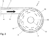
- the hydrocyclone 1 also has a further inlet 5 (in Fig. 2 shown) for the barrier fluid flow 7, which is also fed tangentially to the inlet area 2 here.
- the barrier fluid 7 is, for example, water, alcohol or oil.
- the barrier fluid flow 7 and the feed sludge 6 are fed separately to the hydrocyclone 1 and separated from one another in the hydrocyclone 1 by the lamella 10.
- the lamella 10 is, for example, a cylindrical, thin-walled component made of metal.
- the pure barrier fluid flow 7 meets at the lower end 13 of the lamella 10 with the actual suspension flow (feed slurry 6). This takes place as soon as the flows from the barrier fluid 7 and the feed sludge 6 are stable.
- the distance z from the lower end of the lamella 10 to the transition from the conical section 15 to the cylindrical section 18 is less than 100 mm here.
- the lamella 10 here has compensation openings 17 which represent a connection between the feed sludge 6 and the barrier fluid flow 7, resulting in a pressure compensation between barrier fluid 7 and suspension 6. These compensation holes are also conceivable in the area of inlet 5.
- the flow arrows indicate that the barrier fluid flow 7 and the feed sludge 6 mix with one another as little as possible.
- the barrier fluid flow 7 thus forms a barrier fluid layer 7 towards the wall of the conical section 15.
- the deposited coarse material has enough space to move in a targeted manner in the direction of the underflow discharge pipe 8 by means of a rotary movement.
- this extension prevents the core flow from breaking through into the actual underflow (11).
- the mouth opening 14 of the overflow nozzle 9 ends here in the area below the end 13 of the lamella 10.
- the separation of the heavy part fraction (coarse matter) will be more or less sharp.
- Figure 2 shows a cross-section through a hydrocyclone 1 according to the invention in the area of the inlet.
- the tangential inlet 4 for the feed pulp 6 and the tangential inlet 5 for the barrier fluid layer 7.
- These two inlets 4, 5 open here essentially parallel into the inlet area 2.
- Fig. 3 shows a further embodiment of the hydrocyclone 1 according to the invention.
- the diameter D1 of the inlet area is here 75 mm and the inner diameter D2 of the overflow nozzle is 25 mm.
- This hydrocyclone 1 has a conical lamella 10 which extends into the conical section 15 of the separation area 3.
- the further inlet 5 for the supply of the barrier fluid 7 is located between the conical lamella 10 and the conical section 15 of the separation area 3.
- the cylindrical section 18 adjoining the conical section 15 here has a height y of 150 mm and a diameter x of 37 mm on.
- the underflow discharge pipe 8 with an initial diameter d2 of 25 mm and a final diameter of 10 mm is arranged below the cylindrical section 18.
- the jump in the diameter in the underflow nozzle occurs here because a nozzle 19 for discharging the underflow 11 is inserted into the underflow discharge pipe 8 here.
- the underflow nozzle can also have a uniform diameter of, for example, 10 mm.
- the dimensions given here relate to a hydrocyclone that has achieved very good results in the test facility. Of course, it is possible that dimensions deviating from this also achieve very good results.
Landscapes
- Physics & Mathematics (AREA)
- Fluid Mechanics (AREA)
- Geometry (AREA)
- Cyclones (AREA)
Claims (10)
- Hydrocyclone (1) doté d'une zone de surverse (2) ayant une surverse tangentielle (4) pour une boue dense (6) et une autre zone de séparation (3) adjacente à la zone de surverse (2) ayant un tube d'évacuation de sousverse (8) pour évacuer des matières lourdes ou le gros grain, une buse d'écoulement supérieur (9) en forme de tube plongeur s'avançant axialement à l'intérieur de l'hydrocyclone (1), et dans la zone de la surverse tangentielle (4) au moins une autre surverse (5) servant à acheminer un flux fluide de barrage (7), le fluide de barrage (7) et la boue dense (6) pouvant être réunis dans l'hydrocyclone (1) et , avant qu'ils ne soient réunis, pouvant être séparés l'un de l'autre par une lamelle (10), caractérisé en ce que la zone de séparation (3) se compose d'une partie conique (15) et d'une partie cylindrique adjacente (18) à celle-ci au-dessus du tube d'évacuation de sousverse (8).
- Hydrocyclone (1) selon la revendication 1, caractérisé en ce que le diamètre (x) de la partie cylindrique (18) est inférieur à la hauteur (y) de la partie cylindrique (18).
- Hydrocyclone (1) selon la revendication 1 ou 2, caractérisé en ce que la transition entre la partie conique (15) et la partie cylindrique (18) se situe au maximum à 100 mm après l'alimentation en fluide de barrage.
- Hydrocyclone (1) selon l'une des revendications 1 à 3, caractérisé en ce que le diamètre (x) de la partie cylindrique (18) est d'au moins 25 mm, de préférence d'au moins 30 mm.
- Hydrocyclone (1) selon l'une des revendications 1 à 4, caractérisé en ce que la lamelle (10) est sensiblement cylindrique.
- Hydrocyclone (1) selon l'une des revendications 1 à 4, caractérisé en ce que la lamelle (10) est sensiblement conique.
- Hydrocyclone (1) selon l'une des revendications 1 à 6, caractérisé en ce que la lamelle (10) dans la zone de surverse (2) s'étend jusqu'à la transition avec la zone de séparation (3) .
- Hydrocyclone (1) selon l'une des revendications 1 à 6, caractérisé en ce que la lamelle (10) s'étend jusque dans la zone de séparation (3).
- Hydrocyclone (1) selon l'une des revendications 1 à 8, caractérisé en ce que l'embouchure (14) de la buse d'écoulement supérieur (9) s'étend jusque dans la zone, dans laquelle sont acheminés conjointement le flux de fluide de barrage (7) et la boue dense (6).
- Hydrocyclone (1) selon l'une des revendications 1 à 9, caractérisé en ce que la lamelle (10) se termine en pointe à son extrémité inférieure (13) de manière à réunir le flux de fluide de barrage (7) et la boue dense(6), si possible sans tourbillon.
Priority Applications (2)
| Application Number | Priority Date | Filing Date | Title |
|---|---|---|---|
| PL16180341T PL3132856T3 (pl) | 2015-08-21 | 2016-07-20 | Hydrocyklon z redukcją materiału drobnoziarnistego w biegu dolnym cyklonu |
| RS20211440A RS62791B1 (sr) | 2015-08-21 | 2016-07-20 | Hidrociklon sa smanjenjem finih materijala u otoku ciklona |
Applications Claiming Priority (1)
| Application Number | Priority Date | Filing Date | Title |
|---|---|---|---|
| ATA557/2015A AT516856B1 (de) | 2015-08-21 | 2015-08-21 | Hydrozyklon mit Feinstoffabreicherung im Zyklonunterlauf |
Publications (2)
| Publication Number | Publication Date |
|---|---|
| EP3132856A1 EP3132856A1 (fr) | 2017-02-22 |
| EP3132856B1 true EP3132856B1 (fr) | 2021-09-01 |
Family
ID=56497656
Family Applications (1)
| Application Number | Title | Priority Date | Filing Date |
|---|---|---|---|
| EP16180341.6A Active EP3132856B1 (fr) | 2015-08-21 | 2016-07-20 | Hydrocyclone à appauvrissement en matières fines dans le tamisat inférieur du cyclone |
Country Status (5)
| Country | Link |
|---|---|
| US (1) | US9884325B2 (fr) |
| EP (1) | EP3132856B1 (fr) |
| AT (1) | AT516856B1 (fr) |
| PL (1) | PL3132856T3 (fr) |
| RS (1) | RS62791B1 (fr) |
Families Citing this family (4)
| Publication number | Priority date | Publication date | Assignee | Title |
|---|---|---|---|---|
| US9858925B2 (en) * | 2009-06-05 | 2018-01-02 | Apple Inc. | Using context information to facilitate processing of commands in a virtual assistant |
| WO2019232195A1 (fr) | 2018-05-30 | 2019-12-05 | Chemtreat, Inc. | Système de désulfuration de gaz de combustion et procédé pour effectuer une désulfuration de gaz de combustion |
| CN108643964B (zh) * | 2018-07-10 | 2023-12-22 | 长沙矿山研究院有限责任公司 | 一种分级尾砂充填系统中的旋流器底流消能器及消能方法 |
| CN113369027A (zh) * | 2021-07-28 | 2021-09-10 | 东北大学 | 多级旋流分离柱 |
Family Cites Families (20)
| Publication number | Priority date | Publication date | Assignee | Title |
|---|---|---|---|---|
| US1509915A (en) * | 1922-11-09 | 1924-09-30 | Albert H Stebbins | Concentrator |
| BE544291A (fr) * | 1955-03-10 | 1900-01-01 | Horace Freeman | |
| NL284340A (fr) * | 1961-10-16 | |||
| US3331193A (en) * | 1964-03-23 | 1967-07-18 | Bauer Bros Co | Cyclonic separator |
| SE357309B (fr) * | 1969-03-21 | 1973-06-25 | Celleco Ab | |
| US3507397A (en) * | 1969-04-09 | 1970-04-21 | William R Robinson | Hydrocyclone unit |
| SE407751B (sv) * | 1976-03-26 | 1979-04-23 | Celleco Ab | Anordning vid en hydrocyklon |
| AU580252B2 (en) * | 1983-02-24 | 1984-08-30 | Conoco Specialty Products Inc. | Improved outlet for cyclone separators |
| US4623458A (en) * | 1983-07-19 | 1986-11-18 | Hakola Gordon R | Quick release expendable apex apparatus with bonded liner |
| US4652363A (en) * | 1984-11-01 | 1987-03-24 | Miller Francis G | Dual feed hydrocyclone and method of separating aqueous slurry |
| US4696737A (en) * | 1986-02-28 | 1987-09-29 | The Bauer Bros. Co. | Fiber recovery elutriating hydrocyclone |
| IN165474B (fr) * | 1986-04-23 | 1989-10-28 | Noel Carroll | |
| US4969934A (en) * | 1989-08-04 | 1990-11-13 | The United States Of America As Represented By The United States Department Of Energy | Method for improved gas-solids separation |
| JPH10151371A (ja) * | 1996-11-26 | 1998-06-09 | Ube Ind Ltd | サイクロン |
| US7255790B2 (en) * | 2001-03-26 | 2007-08-14 | Weir Warman Ltd. | Hydrocyclones |
| CL2003001757A1 (es) * | 2003-08-29 | 2005-01-21 | Vulco Sa | Cabezal de entrada para hidrociclon, en el cual la altura del buscador de vortice, es una fraccion de la altura de la entrada de alimentacion, la cual es rectangular, donde dicha entrada tiene un primer sector que forma una voluta horizontal, y un se |
| US7185765B2 (en) * | 2003-11-19 | 2007-03-06 | Hakola Gordon R | Cyclone with in-situ replaceable liner system and method for accomplishing same |
| IL178234A (en) * | 2006-09-21 | 2013-05-30 | Vortex Ecological Technologies Ltd | Cyclone vortex separator |
| AT512479B1 (de) * | 2012-02-10 | 2013-11-15 | Andritz Energy & Environment Gmbh | Verfahren zur feinstoffreduktion im rea-gips |
| AT511837B1 (de) * | 2012-02-10 | 2013-03-15 | Andritz Energy & Environment Gmbh | Hydrozyklon mit feinstoffabreicherung im zyklonunterlauf |
-
2015
- 2015-08-21 AT ATA557/2015A patent/AT516856B1/de active
-
2016
- 2016-07-20 EP EP16180341.6A patent/EP3132856B1/fr active Active
- 2016-07-20 RS RS20211440A patent/RS62791B1/sr unknown
- 2016-07-20 PL PL16180341T patent/PL3132856T3/pl unknown
- 2016-08-08 US US15/230,583 patent/US9884325B2/en active Active
Also Published As
| Publication number | Publication date |
|---|---|
| US9884325B2 (en) | 2018-02-06 |
| AT516856A4 (de) | 2016-09-15 |
| AT516856B1 (de) | 2016-09-15 |
| EP3132856A1 (fr) | 2017-02-22 |
| RS62791B1 (sr) | 2022-02-28 |
| US20170050191A1 (en) | 2017-02-23 |
| PL3132856T3 (pl) | 2022-01-24 |
Similar Documents
| Publication | Publication Date | Title |
|---|---|---|
| AT511837B1 (de) | Hydrozyklon mit feinstoffabreicherung im zyklonunterlauf | |
| EP3132856B1 (fr) | Hydrocyclone à appauvrissement en matières fines dans le tamisat inférieur du cyclone | |
| DE754339C (de) | Verfahren und Vorrichtung zum Entfernen von schweren Teilchen unter Fliehkraftwirkung aus einer Aufschwemmung, insbesondere von Zellstoff, Papierstoff u. dgl. | |
| EP2812122B1 (fr) | Procédé de réduction de matière fine dans un plâtre produit au moyen d'une installation de désulfuration des gaz de fumée (rea) | |
| WO1997016253A2 (fr) | Separateur des matieres legeres du sable et du gravier | |
| DE2147549A1 (de) | Sichter fuer feinkoerniges gut | |
| AT518392B1 (de) | Hydrozyklon mit speziellem Unterlaufaustragsrohr | |
| DE19508430A1 (de) | Hydrozyklon | |
| EP1925896B1 (fr) | Dispositif destiné à l'introduction de ferrailles dans un métal en fusion | |
| WO2015066746A1 (fr) | Procédé pour la séparation de particules solides par l'utilisation d'un séparateur à force centrifuge | |
| EP3524357A1 (fr) | Dispositif separateur | |
| DE1442501B2 (de) | Hydrocyklon | |
| DE3248039A1 (de) | Wirbelsichter zum abscheiden von verunreinigungen aus stoffsuspensionen | |
| DE19963284A1 (de) | Hydrozyklonanordnung | |
| DE966080C (de) | Trennschleuder | |
| AT521979B1 (de) | Vorrichtung zum Filtern von Partikeln | |
| EP2711082A2 (fr) | Hydrocyclone | |
| DE899931C (de) | Verfahren und Vorrichtung zur Klassierung von Gemischen nach Fallgeschwindigkeit im aufsteigenden Fluessigkeitsstrom | |
| DE1442501C (de) | Hydrocyklon | |
| DE1231672B (de) | Verfahren zum Klassieren von in einer Fluessigkeit aufgeschwemmten festen Partikelchen sowie Hydrozyklon zum Ausfuehren des Verfahrens | |
| DD154198A1 (de) | Wirbler ohne stroemungsumkehr | |
| DE1442375C (de) | Hydrozyklonabscheider | |
| EP4370743A1 (fr) | Ensemble hydrocyclone pour séparation centrifuge de solides d'une suspension | |
| DE1442372C (de) | Hydrozyklon-Abscheider | |
| WO2019106005A1 (fr) | Dispositif pour séparer les sédiments de liquides, dispositif de nettoyage et procédé pour séparer les sédiments |
Legal Events
| Date | Code | Title | Description |
|---|---|---|---|
| PUAI | Public reference made under article 153(3) epc to a published international application that has entered the european phase |
Free format text: ORIGINAL CODE: 0009012 |
|
| STAA | Information on the status of an ep patent application or granted ep patent |
Free format text: STATUS: THE APPLICATION HAS BEEN PUBLISHED |
|
| AK | Designated contracting states |
Kind code of ref document: A1 Designated state(s): AL AT BE BG CH CY CZ DE DK EE ES FI FR GB GR HR HU IE IS IT LI LT LU LV MC MK MT NL NO PL PT RO RS SE SI SK SM TR |
|
| AX | Request for extension of the european patent |
Extension state: BA ME |
|
| STAA | Information on the status of an ep patent application or granted ep patent |
Free format text: STATUS: REQUEST FOR EXAMINATION WAS MADE |
|
| 17P | Request for examination filed |
Effective date: 20170725 |
|
| RBV | Designated contracting states (corrected) |
Designated state(s): AL AT BE BG CH CY CZ DE DK EE ES FI FR GB GR HR HU IE IS IT LI LT LU LV MC MK MT NL NO PL PT RO RS SE SI SK SM TR |
|
| GRAP | Despatch of communication of intention to grant a patent |
Free format text: ORIGINAL CODE: EPIDOSNIGR1 |
|
| STAA | Information on the status of an ep patent application or granted ep patent |
Free format text: STATUS: GRANT OF PATENT IS INTENDED |
|
| RIC1 | Information provided on ipc code assigned before grant |
Ipc: B04C 9/00 20060101ALI20210401BHEP Ipc: B04C 5/103 20060101ALI20210401BHEP Ipc: B04C 5/14 20060101ALI20210401BHEP Ipc: B04C 5/081 20060101ALI20210401BHEP Ipc: B04C 5/04 20060101AFI20210401BHEP |
|
| INTG | Intention to grant announced |
Effective date: 20210428 |
|
| GRAS | Grant fee paid |
Free format text: ORIGINAL CODE: EPIDOSNIGR3 |
|
| GRAA | (expected) grant |
Free format text: ORIGINAL CODE: 0009210 |
|
| STAA | Information on the status of an ep patent application or granted ep patent |
Free format text: STATUS: THE PATENT HAS BEEN GRANTED |
|
| AK | Designated contracting states |
Kind code of ref document: B1 Designated state(s): AL AT BE BG CH CY CZ DE DK EE ES FI FR GB GR HR HU IE IS IT LI LT LU LV MC MK MT NL NO PL PT RO RS SE SI SK SM TR |
|
| REG | Reference to a national code |
Ref country code: GB Ref legal event code: FG4D Free format text: NOT ENGLISH |
|
| REG | Reference to a national code |
Ref country code: CH Ref legal event code: EP Ref country code: AT Ref legal event code: REF Ref document number: 1425647 Country of ref document: AT Kind code of ref document: T Effective date: 20210915 |
|
| REG | Reference to a national code |
Ref country code: DE Ref legal event code: R096 Ref document number: 502016013738 Country of ref document: DE |
|
| REG | Reference to a national code |
Ref country code: IE Ref legal event code: FG4D Free format text: LANGUAGE OF EP DOCUMENT: GERMAN |
|
| REG | Reference to a national code |
Ref country code: SE Ref legal event code: TRGR |
|
| REG | Reference to a national code |
Ref country code: LT Ref legal event code: MG9D |
|
| REG | Reference to a national code |
Ref country code: NL Ref legal event code: MP Effective date: 20210901 |
|
| PG25 | Lapsed in a contracting state [announced via postgrant information from national office to epo] |
Ref country code: ES Free format text: LAPSE BECAUSE OF FAILURE TO SUBMIT A TRANSLATION OF THE DESCRIPTION OR TO PAY THE FEE WITHIN THE PRESCRIBED TIME-LIMIT Effective date: 20210901 Ref country code: FI Free format text: LAPSE BECAUSE OF FAILURE TO SUBMIT A TRANSLATION OF THE DESCRIPTION OR TO PAY THE FEE WITHIN THE PRESCRIBED TIME-LIMIT Effective date: 20210901 Ref country code: NO Free format text: LAPSE BECAUSE OF FAILURE TO SUBMIT A TRANSLATION OF THE DESCRIPTION OR TO PAY THE FEE WITHIN THE PRESCRIBED TIME-LIMIT Effective date: 20211201 Ref country code: LT Free format text: LAPSE BECAUSE OF FAILURE TO SUBMIT A TRANSLATION OF THE DESCRIPTION OR TO PAY THE FEE WITHIN THE PRESCRIBED TIME-LIMIT Effective date: 20210901 Ref country code: BG Free format text: LAPSE BECAUSE OF FAILURE TO SUBMIT A TRANSLATION OF THE DESCRIPTION OR TO PAY THE FEE WITHIN THE PRESCRIBED TIME-LIMIT Effective date: 20211201 Ref country code: HR Free format text: LAPSE BECAUSE OF FAILURE TO SUBMIT A TRANSLATION OF THE DESCRIPTION OR TO PAY THE FEE WITHIN THE PRESCRIBED TIME-LIMIT Effective date: 20210901 |
|
| PG25 | Lapsed in a contracting state [announced via postgrant information from national office to epo] |
Ref country code: LV Free format text: LAPSE BECAUSE OF FAILURE TO SUBMIT A TRANSLATION OF THE DESCRIPTION OR TO PAY THE FEE WITHIN THE PRESCRIBED TIME-LIMIT Effective date: 20210901 Ref country code: GR Free format text: LAPSE BECAUSE OF FAILURE TO SUBMIT A TRANSLATION OF THE DESCRIPTION OR TO PAY THE FEE WITHIN THE PRESCRIBED TIME-LIMIT Effective date: 20211202 |
|
| PG25 | Lapsed in a contracting state [announced via postgrant information from national office to epo] |
Ref country code: IS Free format text: LAPSE BECAUSE OF FAILURE TO SUBMIT A TRANSLATION OF THE DESCRIPTION OR TO PAY THE FEE WITHIN THE PRESCRIBED TIME-LIMIT Effective date: 20220101 Ref country code: SM Free format text: LAPSE BECAUSE OF FAILURE TO SUBMIT A TRANSLATION OF THE DESCRIPTION OR TO PAY THE FEE WITHIN THE PRESCRIBED TIME-LIMIT Effective date: 20210901 Ref country code: SK Free format text: LAPSE BECAUSE OF FAILURE TO SUBMIT A TRANSLATION OF THE DESCRIPTION OR TO PAY THE FEE WITHIN THE PRESCRIBED TIME-LIMIT Effective date: 20210901 Ref country code: RO Free format text: LAPSE BECAUSE OF FAILURE TO SUBMIT A TRANSLATION OF THE DESCRIPTION OR TO PAY THE FEE WITHIN THE PRESCRIBED TIME-LIMIT Effective date: 20210901 Ref country code: PT Free format text: LAPSE BECAUSE OF FAILURE TO SUBMIT A TRANSLATION OF THE DESCRIPTION OR TO PAY THE FEE WITHIN THE PRESCRIBED TIME-LIMIT Effective date: 20220103 Ref country code: NL Free format text: LAPSE BECAUSE OF FAILURE TO SUBMIT A TRANSLATION OF THE DESCRIPTION OR TO PAY THE FEE WITHIN THE PRESCRIBED TIME-LIMIT Effective date: 20210901 Ref country code: EE Free format text: LAPSE BECAUSE OF FAILURE TO SUBMIT A TRANSLATION OF THE DESCRIPTION OR TO PAY THE FEE WITHIN THE PRESCRIBED TIME-LIMIT Effective date: 20210901 Ref country code: CZ Free format text: LAPSE BECAUSE OF FAILURE TO SUBMIT A TRANSLATION OF THE DESCRIPTION OR TO PAY THE FEE WITHIN THE PRESCRIBED TIME-LIMIT Effective date: 20210901 Ref country code: AL Free format text: LAPSE BECAUSE OF FAILURE TO SUBMIT A TRANSLATION OF THE DESCRIPTION OR TO PAY THE FEE WITHIN THE PRESCRIBED TIME-LIMIT Effective date: 20210901 |
|
| REG | Reference to a national code |
Ref country code: DE Ref legal event code: R097 Ref document number: 502016013738 Country of ref document: DE |
|
| PLBE | No opposition filed within time limit |
Free format text: ORIGINAL CODE: 0009261 |
|
| STAA | Information on the status of an ep patent application or granted ep patent |
Free format text: STATUS: NO OPPOSITION FILED WITHIN TIME LIMIT |
|
| PG25 | Lapsed in a contracting state [announced via postgrant information from national office to epo] |
Ref country code: IT Free format text: LAPSE BECAUSE OF FAILURE TO SUBMIT A TRANSLATION OF THE DESCRIPTION OR TO PAY THE FEE WITHIN THE PRESCRIBED TIME-LIMIT Effective date: 20210901 Ref country code: DK Free format text: LAPSE BECAUSE OF FAILURE TO SUBMIT A TRANSLATION OF THE DESCRIPTION OR TO PAY THE FEE WITHIN THE PRESCRIBED TIME-LIMIT Effective date: 20210901 |
|
| 26N | No opposition filed |
Effective date: 20220602 |
|
| PG25 | Lapsed in a contracting state [announced via postgrant information from national office to epo] |
Ref country code: SI Free format text: LAPSE BECAUSE OF FAILURE TO SUBMIT A TRANSLATION OF THE DESCRIPTION OR TO PAY THE FEE WITHIN THE PRESCRIBED TIME-LIMIT Effective date: 20210901 |
|
| PG25 | Lapsed in a contracting state [announced via postgrant information from national office to epo] |
Ref country code: MC Free format text: LAPSE BECAUSE OF FAILURE TO SUBMIT A TRANSLATION OF THE DESCRIPTION OR TO PAY THE FEE WITHIN THE PRESCRIBED TIME-LIMIT Effective date: 20210901 |
|
| REG | Reference to a national code |
Ref country code: CH Ref legal event code: PL |
|
| GBPC | Gb: european patent ceased through non-payment of renewal fee |
Effective date: 20220720 |
|
| REG | Reference to a national code |
Ref country code: BE Ref legal event code: MM Effective date: 20220731 |
|
| PG25 | Lapsed in a contracting state [announced via postgrant information from national office to epo] |
Ref country code: LU Free format text: LAPSE BECAUSE OF NON-PAYMENT OF DUE FEES Effective date: 20220720 Ref country code: LI Free format text: LAPSE BECAUSE OF NON-PAYMENT OF DUE FEES Effective date: 20220731 Ref country code: FR Free format text: LAPSE BECAUSE OF NON-PAYMENT OF DUE FEES Effective date: 20220731 Ref country code: CH Free format text: LAPSE BECAUSE OF NON-PAYMENT OF DUE FEES Effective date: 20220731 |
|
| PG25 | Lapsed in a contracting state [announced via postgrant information from national office to epo] |
Ref country code: GB Free format text: LAPSE BECAUSE OF NON-PAYMENT OF DUE FEES Effective date: 20220720 Ref country code: BE Free format text: LAPSE BECAUSE OF NON-PAYMENT OF DUE FEES Effective date: 20220731 |
|
| PG25 | Lapsed in a contracting state [announced via postgrant information from national office to epo] |
Ref country code: IE Free format text: LAPSE BECAUSE OF NON-PAYMENT OF DUE FEES Effective date: 20220720 |
|
| REG | Reference to a national code |
Ref country code: AT Ref legal event code: MM01 Ref document number: 1425647 Country of ref document: AT Kind code of ref document: T Effective date: 20220720 |
|
| PG25 | Lapsed in a contracting state [announced via postgrant information from national office to epo] |
Ref country code: AT Free format text: LAPSE BECAUSE OF NON-PAYMENT OF DUE FEES Effective date: 20220720 |
|
| PGFP | Annual fee paid to national office [announced via postgrant information from national office to epo] |
Ref country code: TR Payment date: 20230717 Year of fee payment: 8 |
|
| PGFP | Annual fee paid to national office [announced via postgrant information from national office to epo] |
Ref country code: SE Payment date: 20230719 Year of fee payment: 8 Ref country code: RS Payment date: 20230706 Year of fee payment: 8 Ref country code: PL Payment date: 20230707 Year of fee payment: 8 Ref country code: DE Payment date: 20230719 Year of fee payment: 8 |
|
| PG25 | Lapsed in a contracting state [announced via postgrant information from national office to epo] |
Ref country code: HU Free format text: LAPSE BECAUSE OF FAILURE TO SUBMIT A TRANSLATION OF THE DESCRIPTION OR TO PAY THE FEE WITHIN THE PRESCRIBED TIME-LIMIT; INVALID AB INITIO Effective date: 20160720 |
|
| PG25 | Lapsed in a contracting state [announced via postgrant information from national office to epo] |
Ref country code: MK Free format text: LAPSE BECAUSE OF FAILURE TO SUBMIT A TRANSLATION OF THE DESCRIPTION OR TO PAY THE FEE WITHIN THE PRESCRIBED TIME-LIMIT Effective date: 20210901 Ref country code: CY Free format text: LAPSE BECAUSE OF FAILURE TO SUBMIT A TRANSLATION OF THE DESCRIPTION OR TO PAY THE FEE WITHIN THE PRESCRIBED TIME-LIMIT Effective date: 20210901 |