EP3132580B1 - Kanalschätzung in einem drahtloskommunikationssystemknoten - Google Patents
Kanalschätzung in einem drahtloskommunikationssystemknoten Download PDFInfo
- Publication number
- EP3132580B1 EP3132580B1 EP14722667.4A EP14722667A EP3132580B1 EP 3132580 B1 EP3132580 B1 EP 3132580B1 EP 14722667 A EP14722667 A EP 14722667A EP 3132580 B1 EP3132580 B1 EP 3132580B1
- Authority
- EP
- European Patent Office
- Prior art keywords
- network node
- radio network
- user equipment
- pilot signal
- signal
- Prior art date
- Legal status (The legal status is an assumption and is not a legal conclusion. Google has not performed a legal analysis and makes no representation as to the accuracy of the status listed.)
- Active
Links
Images

Classifications
-
- H—ELECTRICITY
- H04—ELECTRIC COMMUNICATION TECHNIQUE
- H04W—WIRELESS COMMUNICATION NETWORKS
- H04W72/00—Local resource management
- H04W72/50—Allocation or scheduling criteria for wireless resources
- H04W72/54—Allocation or scheduling criteria for wireless resources based on quality criteria
- H04W72/541—Allocation or scheduling criteria for wireless resources based on quality criteria using the level of interference
-
- H—ELECTRICITY
- H04—ELECTRIC COMMUNICATION TECHNIQUE
- H04B—TRANSMISSION
- H04B7/00—Radio transmission systems, i.e. using radiation field
- H04B7/02—Diversity systems; Multi-antenna system, i.e. transmission or reception using multiple antennas
- H04B7/04—Diversity systems; Multi-antenna system, i.e. transmission or reception using multiple antennas using two or more spaced independent antennas
- H04B7/0413—MIMO systems
- H04B7/0452—Multi-user MIMO systems
-
- H—ELECTRICITY
- H04—ELECTRIC COMMUNICATION TECHNIQUE
- H04B—TRANSMISSION
- H04B7/00—Radio transmission systems, i.e. using radiation field
- H04B7/02—Diversity systems; Multi-antenna system, i.e. transmission or reception using multiple antennas
- H04B7/04—Diversity systems; Multi-antenna system, i.e. transmission or reception using multiple antennas using two or more spaced independent antennas
- H04B7/08—Diversity systems; Multi-antenna system, i.e. transmission or reception using multiple antennas using two or more spaced independent antennas at the receiving station
- H04B7/0837—Diversity systems; Multi-antenna system, i.e. transmission or reception using multiple antennas using two or more spaced independent antennas at the receiving station using pre-detection combining
- H04B7/0842—Weighted combining
- H04B7/0848—Joint weighting
- H04B7/0854—Joint weighting using error minimizing algorithms, e.g. minimum mean squared error [MMSE], "cross-correlation" or matrix inversion
-
- H—ELECTRICITY
- H04—ELECTRIC COMMUNICATION TECHNIQUE
- H04B—TRANSMISSION
- H04B7/00—Radio transmission systems, i.e. using radiation field
- H04B7/02—Diversity systems; Multi-antenna system, i.e. transmission or reception using multiple antennas
- H04B7/04—Diversity systems; Multi-antenna system, i.e. transmission or reception using multiple antennas using two or more spaced independent antennas
- H04B7/08—Diversity systems; Multi-antenna system, i.e. transmission or reception using multiple antennas using two or more spaced independent antennas at the receiving station
- H04B7/0868—Hybrid systems, i.e. switching and combining
- H04B7/0874—Hybrid systems, i.e. switching and combining using subgroups of receive antennas
-
- H—ELECTRICITY
- H04—ELECTRIC COMMUNICATION TECHNIQUE
- H04L—TRANSMISSION OF DIGITAL INFORMATION, e.g. TELEGRAPHIC COMMUNICATION
- H04L25/00—Baseband systems
- H04L25/02—Details ; arrangements for supplying electrical power along data transmission lines
- H04L25/0202—Channel estimation
- H04L25/0224—Channel estimation using sounding signals
-
- H—ELECTRICITY
- H04—ELECTRIC COMMUNICATION TECHNIQUE
- H04L—TRANSMISSION OF DIGITAL INFORMATION, e.g. TELEGRAPHIC COMMUNICATION
- H04L25/00—Baseband systems
- H04L25/02—Details ; arrangements for supplying electrical power along data transmission lines
- H04L25/0202—Channel estimation
- H04L25/0224—Channel estimation using sounding signals
- H04L25/0226—Channel estimation using sounding signals sounding signals per se
-
- H—ELECTRICITY
- H04—ELECTRIC COMMUNICATION TECHNIQUE
- H04L—TRANSMISSION OF DIGITAL INFORMATION, e.g. TELEGRAPHIC COMMUNICATION
- H04L5/00—Arrangements affording multiple use of the transmission path
- H04L5/003—Arrangements for allocating sub-channels of the transmission path
- H04L5/0032—Distributed allocation, i.e. involving a plurality of allocating devices, each making partial allocation
- H04L5/0035—Resource allocation in a cooperative multipoint environment
-
- H—ELECTRICITY
- H04—ELECTRIC COMMUNICATION TECHNIQUE
- H04L—TRANSMISSION OF DIGITAL INFORMATION, e.g. TELEGRAPHIC COMMUNICATION
- H04L5/00—Arrangements affording multiple use of the transmission path
- H04L5/003—Arrangements for allocating sub-channels of the transmission path
- H04L5/0048—Allocation of pilot signals, i.e. of signals known to the receiver
- H04L5/0051—Allocation of pilot signals, i.e. of signals known to the receiver of dedicated pilots, i.e. pilots destined for a single user or terminal
-
- H—ELECTRICITY
- H04—ELECTRIC COMMUNICATION TECHNIQUE
- H04L—TRANSMISSION OF DIGITAL INFORMATION, e.g. TELEGRAPHIC COMMUNICATION
- H04L25/00—Baseband systems
- H04L25/02—Details ; arrangements for supplying electrical power along data transmission lines
- H04L25/0202—Channel estimation
- H04L25/0224—Channel estimation using sounding signals
- H04L25/0228—Channel estimation using sounding signals with direct estimation from sounding signals
-
- H—ELECTRICITY
- H04—ELECTRIC COMMUNICATION TECHNIQUE
- H04W—WIRELESS COMMUNICATION NETWORKS
- H04W72/00—Local resource management
- H04W72/04—Wireless resource allocation
- H04W72/044—Wireless resource allocation based on the type of the allocated resource
- H04W72/046—Wireless resource allocation based on the type of the allocated resource the resource being in the space domain, e.g. beams
-
- H—ELECTRICITY
- H04—ELECTRIC COMMUNICATION TECHNIQUE
- H04W—WIRELESS COMMUNICATION NETWORKS
- H04W72/00—Local resource management
- H04W72/50—Allocation or scheduling criteria for wireless resources
- H04W72/54—Allocation or scheduling criteria for wireless resources based on quality criteria
- H04W72/542—Allocation or scheduling criteria for wireless resources based on quality criteria using measured or perceived quality
Definitions
- Implementations described herein generally relate to a radio network node, a method in a radio network node, a computer program product and a coordinated multipoint scheme for orthogonal pilot signal scheduling.
- a mechanism is herein described for channel estimation of a channel used for wireless signal communication between a user equipment and the radio network node in a wireless communication system comprising Massive MIMO.
- a User Equipment also known as a mobile station, wireless terminal and/ or mobile terminal is enabled to communicate wirelessly in a wireless communication network, sometimes also referred to as a cellular radio system.
- the communication may be made, e.g., between user equipments, between a user equipment and a wire connected telephone and/ or between a user equipment and a server via a Radio Access Network (RAN) and possibly one or more core networks.
- RAN Radio Access Network
- the wireless communication may comprise various communication services such as voice, messaging, packet data, video, broadcast, etc.
- the user equipment may further be referred to as mobile telephone, cellular telephone, computer tablet or laptop with wireless capability, etc.
- the user equipment in the present context may be, for example, portable, pocket-storable, hand-held, computer-comprised, or vehicle-mounted mobile devices, enabled to communicate voice and/ or data, via the radio access network, with another entity, such as another user equipment, a stationary entity or a server.
- the wireless communication network covers a geographical area which is divided into cell areas, with each cell area being served by a radio network node or base station, e.g., a Radio Base Station (RBS) or Base Transceiver Station (BTS), which in some networks may be referred to as "eNB”, “eNodeB”, “NodeB” or “B node”, depending on the technology and/ or terminology used.
- a radio network node or base station e.g., a Radio Base Station (RBS) or Base Transceiver Station (BTS)
- eNB Radio Base Station
- eNodeB NodeB
- NodeB NodeB node
- the expression "cell” may be used for denoting the radio network node itself. However, the cell may also in normal terminology be used for the geographical area where radio coverage is provided by the radio network node at a base station site.
- One radio network node, situated on the base station site, may serve one or several cells.
- the radio network nodes may communicate over the air interface operating on radio frequencies with any user equipment within range of the respective radio network node.
- radio network nodes may be connected, e.g., by landlines or microwave, to a Radio Network Controller (RNC), e.g., in Universal Mobile Telecommunications System (UMTS).
- RNC Radio Network Controller
- UMTS Universal Mobile Telecommunications System
- BSC Base Station Controller
- GSM Global System for Mobile Communications
- radio network nodes which may be referred to as eNodeBs or eNBs, may be connected to a gateway, e.g., a radio access gateway, to one or more core networks.
- LTE is based on the GSM/ EDGE and UMTS/ HSPA network technologies, increasing the capacity and speed using a different radio interface together with core network improvements.
- LTE-Advanced i.e. LTE Release10 and later releases are set to provide higher bitrates in a cost efficient way and, at the same time, completely fulfil the requirements set by International Telecommunication Union (ITU) for the International Mobile Telecommunications (IMT)-Advanced, sometimes also referred to as 4G (abbreviation for "fourth generation").
- ITU International Telecommunication Union
- 4G abbreviation for "fourth generation”
- 3G mobile communication systems such as e.g., 3GPP LTE, offer high data rate in the downlink by employing multiple antenna systems utilising Multiple-Input and Multiple-Output (MIMO).
- MIMO Multiple-Input and Multiple-Output
- Massive MIMO is a new technology that uses large Antenna Arrays Systems (AAS) with individual transceivers to dramatically improve throughput of wireless communication systems.
- AAS Antenna Arrays Systems
- the benefit of these large arrays is the ability to spatially resolve and separate received and transmitted signals with very high resolution.
- Typical limitation factors like Noise and Interference is reduced to the extent that previously negligible effects become limiting.
- Pilot Contamination is caused by lost or lack of training sequence orthogonality between cells.
- Massive MIMO is sometimes loosely defined as a system comprising e.g. 100 or more transceivers.
- Various investigations in this community have shown Massive MIMO systems that benefit from several hundred's of transceivers.
- a Massive MIMO enabled radio network node estimates the radio channel from user equipments by correlating the received signal with a known signal transmitted by the user equipments, i.e. pilot signals. These pilot signals are made orthogonal to each other. This means that the result of correlation performed by the radio network node during training will only contain a systematic response from desired link form the mobile transmitting the pilot used in the correlation.
- the expressions downlink, downstream link or forward link may be used for the transmission path from the radio network node to the user equipment.
- the expression uplink, upstream link or reverse link may be used for the transmission path in the opposite direction, i.e., from the user equipment to the radio network node.
- WO0211311 relates to apparatus for and methods of receiving a transmission signal.
- US6091788 relates to base station equipment and a method for steering an antenna beam.
- a radio network node is provided according to claim 1.
- An advantage according to such implementation is that the limited amount of available orthogonal pilot signals may be dedicated for the first pilot signal, while an arbitrary, not necessarily orthogonal pilot signal, may be used for the second pilot signal. Thereby, pilot contamination is avoided without requirement of additional amount of orthogonal signals. Thereby pilot signals may be reused, which enables use of a limited amount of available orthogonal pilot signals.
- the processor may be further configured for determining visibility range of arrival for the selected signals; and also configured for designing the receiver pre-filter by isolating pilot signals received from the determined visibility range of arrival.
- An advantage therewith comprises further improved channel estimation, as disturbing signals transmitted by the interferer may be filtered out with improved precision.
- the processor may also be configured for spatial analysing the received signals by comparing the received signal strength with a predetermined threshold value, and also configured for selecting the signals having a signal strength exceeding the predetermined threshold value.
- the uplink signals transmitted by the user equipment may be filtered out and detected with further improved precision.
- the first pilot signal of the user equipment is a Sounding Reference Signal (SRS) and wherein scheduling of the first pilot signal may be coordinated between the radio network node and the neighbour network node.
- the second pilot signal of the user equipment may be a demodulation reference signal (DMRS) or an SRS, which is not required to be coordinated between the radio network node and the neighbour network node.
- an improved channel estimation may be made as problems associated with pilot contamination in a massive MIMO environment is omitted or at least reduced.
- the design of the receiver pre-filter may be based on blind estimations and/ or statistics.
- An advantage of using blind estimations/ statistics is that any received signals may be utilised for the pre-filtering rendering a further improved channel estimation and reduction of pilot contamination.
- the design of the receiver pre-filter may be model based, e.g. based on matched filter signal strength measurements on the first pilot signal received from the user equipment.
- An advantage of using a matched filter tuned for known reference signals such as pilot signals is that interferers may be filtered out, according to some embodiments. Thereby, an improved signal quality of the signal received in the uplink from the user equipment may be achieved.
- the multiple antenna array may comprise a multitude of antenna elements, mounted at a distance from each other such that at least some of the antenna elements are able to receiving the same signal from the user equipment.
- the radio network node may comprise an evolved NodeB (eNodeB) and wherein the wireless communication network may be based on 3rd Generation Partnership Project Long Term Evolution (3GPP LTE).
- eNodeB evolved NodeB
- 3GPP LTE 3rd Generation Partnership Project Long Term Evolution
- massive MIMO and channel estimation according to the disclosed method may be provided also in an existing network and network elements, solving problems associated with pilot contamination.
- An advantage according to such implementation is that the limited amount of available orthogonal pilot signals may be dedicated for the first pilot signal, while an arbitrary, not necessarily orthogonal pilot signal, may be used for the second pilot signal. Thereby, pilot contamination is avoided without requirement of additional amount of orthogonal signals. Thereby pilot signals may be reused, which enables use of a limited amount of available orthogonal pilot signals.
- the method in addition may comprise determining visibility range of arrival for the selected pilot signal; and wherein the design of the receiver pre-filter may be further made for isolating pilot signals received from the determined visibility range of arrival.
- An advantage therewith comprises further improved channel estimation, as disturbing signals transmitted by the interferer may be filtered out with improved precision.
- the spatial analysis of the received signals comprises a comparison of the received signal strength with a predetermined threshold value, and wherein the signals having a signal strength exceeding the predetermined threshold value are selected.
- the uplink signals transmitted by the user equipment may be filtered out and detected with further improved precision.
- the first pilot signal of the user equipment may be a Sounding Reference Signal (SRS) and wherein scheduling of the first pilot signal may be coordinated between the radio network node and the neighbour network node.
- the second pilot signal of the user equipment may be a demodulation reference signal (DMRS) or an SRS, which may not be required to be coordinated between the radio network node and the neighbour network node.
- An advantage according to such implementation comprises improved channel estimation may be made as problems associated with pilot contamination in a massive MIMO environment is omitted or at least reduced.
- the design of the receiver pre-filter may be based on blind estimations and/ or statistics.
- An advantage of using blind estimations/ statistics is that any received signals may be utilised for the pre-filtering rendering a further improved channel estimation and reduction of pilot contamination.
- the design of the receiver pre-filter is model based, e.g. based on matched filter signal strength measurements on the first pilot signal received from the user equipment.
- An advantage of using a matched filter tuned for known reference signals such as pilot signals is that interferers may be filtered out, according to some embodiments. Thereby, an improved signal quality of the signal received in the uplink from the user equipment may be achieved.
- the multiple antenna array may comprise a multitude of antenna elements, mounted at a distance from each other such that at least some of the antenna elements are able to receiving the same signal from the user equipment.
- the radio network node may comprise an evolved NodeB (eNodeB), and wherein the wireless communication network may be based on 3rd Generation Partnership Project Long Term Evolution (3GPP LTE).
- eNodeB evolved NodeB
- 3GPP LTE 3rd Generation Partnership Project Long Term Evolution
- massive MIMO and channel estimation according to the disclosed method may be provided also in an existing network and network elements, solving problems associated with pilot contamination.
- a computer program product is provided according to claim 11.
- Improved channel estimation may thereby be made within the cell, as pilot signals from a user equipment may be filtered out and distinguished from wireless signals transmitted by an interferer.
- problems associated with pilot contamination in a massive MIMO environment is omitted or at least reduced.
- improved channel estimation may thereby be made within the cell, as pilot signals from a user equipment may be filtered out and distinguished from wireless signals transmitted by an interferer.
- problems associated with pilot contamination in a massive MIMO environment is omitted or at least reduced.
- an improved performance within the wireless communication system is provided, while the pilot contamination is reduced at the network side.
- Embodiments of the invention described herein are defined as a radio network node, a method in a radio network node, a computer program product and a coordinated multipoint scheme for orthogonal pilot signal scheduling, which may be put into practice in the embodiments described below. These embodiments may, however, be exemplified and realised in many different forms and are not to be limited to the examples set forth herein; rather, these illustrative examples of embodiments are provided so that this disclosure will be thorough and complete.
- Figure 1 is a schematic illustration over a wireless communication network 100 comprising a radio network node 110, a neighbour radio network node 130, a user equipment 120 and an interferer 230, situated in the neighbour cell of the neighbour radio network node 130.
- the user equipment 120 may be served by the radio network node 110, thereby being connected to the wireless communication network 100.
- the wireless communication network 100 may at least partly be based on radio access technologies such as, e.g., 3GPP LTE, LTE-Advanced, Evolved Universal Terrestrial Radio Access Network (E-UTRAN), Universal Mobile Telecommunications System (UMTS), Global System for Mobile Communications (originally: Groupe Special Mobile) (GSM)/ Enhanced Data rate for GSM Evolution (GSM/EDGE), Wideband Code Division Multiple Access (WCDMA), Time Division Multiple Access (TDMA) networks, Frequency Division Multiple Access (FDMA) networks, Orthogonal FDMA (OFDMA) networks, Single-Carrier FDMA (SC-FDMA) networks, Worldwide Interoperability for Microwave Access (WiMax), or Ultra Mobile Broadband (UMB), High Speed Packet Access (HSPA) Evolved Universal Terrestrial Radio Access (E-UTRA), Universal Terrestrial Radio Access (UTRA), GSM EDGE Radio Access Network (GERAN), 3GPP2 CDMA technologies, e.g., CDMA2000 1x RTT and High
- the wireless communication network 100 may be configured to operate according to the Time Division Duplex (TDD) and/ or the Frequency Division Duplex (FDD) principle, according to different embodiments.
- TDD Time Division Duplex
- FDD Frequency Division Duplex
- TDD is an application of time-division multiplexing to separate uplink and downlink signals in time, possibly with a Guard Period (GP) situated in the time domain between the uplink and downlink signalling.
- FDD means that the transmitter and receiver operate at different carrier frequencies.
- the purpose of the illustration in Figure 1 is to provide a simplified, general overview of the wireless communication network 100 and the involved methods and nodes, such as the radio network node 110, the neighbour network node 130, the user equipment 120 and the interferer 230 herein described, and the functionalities involved.
- the methods, radio network nodes 110, 130; the user equipment 120 and the interferer 230 will subsequently, as a non-limiting example, be described in a 3GPP LTE/ LTE-Advanced environment.
- the disclosed embodiments may operate in a wireless communication network 100 based on another access technology such as, e.g., any of the above already enumerated.
- radio network node network node
- base station base station
- the illustrated radio network node 110 comprised in the wireless communication network 100 may send and receive radio signals in order to communicate wirelessly with the user equipment 120.
- the radio network node 110 may have knowledge about the neighbour network node 130, and time-frequency characteristics, such as periodicity, of transmitted DRS signals, or other reference signals, pilot signals or synchronization signals of the neighbour network node 130 e.g. by communicating with the neighbour network node 130 through an X2 connection, or another similar wired or wireless inter-network node communication interface.
- time-frequency characteristics such as periodicity, of transmitted DRS signals, or other reference signals, pilot signals or synchronization signals of the neighbour network node 130 e.g. by communicating with the neighbour network node 130 through an X2 connection, or another similar wired or wireless inter-network node communication interface.
- the user equipment 120 may send pilot signals in the uplink to be received by the radio network node 110.
- the illustrated network setting of one instance of the radio network node 110, one instance of the neighbour network node 130, one user equipment 120 and one interferer 230 in Figure 1 is to be regarded as a non-limiting example of an embodiment only.
- the wireless communication network 100 may comprise any other number and/ or combination of the discussed radio network nodes 110, 130, user equipments 120, and/ or interferer 230.
- a plurality of user equipments 120 and/ or interferers 230, and/ or another configuration of radio network nodes 110, 130 may thus be involved in some embodiments of the disclosed invention.
- the at least one neighbour network node 130 may comprise a set of a plurality of neighbour network nodes, according to some embodiments.
- radio network node 110 neighbour network node 130, user equipment 120 and/ or interferer 230
- a plurality of the radio network nodes 110, neighbour network nodes 130, user equipment 120 and/ or interferers 230 may be involved, according to some embodiments.
- the radio network node 110 and the neighbour network node 130 may be configured for downlink transmission and uplink reception, and may be referred to, respectively, as e.g., a base station, a NodeB, an evolved Node Bs (eNB, or eNode B), a base transceiver station, an Access Point Base Station, a base station router, a Radio Base Station (RBS), a micro base station, a pico base station, a femto base station, a Home eNodeB, a sensor, a beacon device, a relay node, a repeater or any other network node configured for communication with the user equipment 120 over a wireless interface, depending, e.g., of the radio access technology and/ or terminology used.
- a base station e.g., a NodeB, an evolved Node Bs (eNB, or eNode B), a base transceiver station, an Access Point Base Station, a base station router, a Radio Base Station (RBS),
- the user equipment 120 and/ or the interferer 230 may correspondingly be represented by, e.g. a wireless communication terminal, a mobile cellular phone, a Personal Digital Assistant (PDA), a wireless platform, a user equipment, a tablet computer, a portable communication device, a laptop, a computer, a wireless terminal acting as a relay, a relay node, a mobile relay, a Customer Premises Equipment (CPE), a Fixed Wireless Access (FWA) nodes or any other kind of device configured to communicate wirelessly with the radio network node 110 and/ or the neighbour network node 130, according to different embodiments and different vocabulary.
- PDA Personal Digital Assistant
- a wireless platform e.g. a wireless communication terminal, a mobile cellular phone, a Personal Digital Assistant (PDA), a wireless platform, a user equipment, a tablet computer, a portable communication device, a laptop, a computer, a wireless terminal acting as a relay, a relay node, a mobile relay, a Customer Premises Equipment (
- Some embodiments of the invention may define a modular implementation approach, and make it possible to reuse legacy systems such as e.g. standards, algorithms, implementations, components and products.
- Fading is deviation of the attenuation affecting the transmitted signal.
- the fading may vary with time, geographical position and/ or radio frequency.
- Fading may be either due to multipath propagation, sometimes also referred to as mulipath induced fading, or due to shadowing from obstacles affecting the wave propagation, sometimes referred to as shadow fading.
- the fading may be divided into large scale fading also known as slow fading, and small scale fading, also known as fast fading.
- the amplitude and phase change imposed by the channel may be considered roughly constant over a period of time.
- the amplitude and phase change imposed by the channel may vary considerably over the period of time.
- a sparse coordinated scheduling of a limited set of pilot signals is introduced. It is thereby ensured that the same pilot signal is never transmitted on the same time and frequency slot of both wanted links, i.e. uplink signals from the user equipment 120 in the own cell, and unwanted link, i.e. uplink signals from the interferer 230 situated in the neighbour cell 120.
- the small scale fading is essentially related to the geometry of the scenario, i.e. the angle and distance to scattering, transmitting and receiving objects in the environment.
- some embodiments comprises extensive re-use of training sequences. Discrimination of unwanted signals, and thus elimination of pilot contamination, are done based on their large scale parameters, essentially angle of arrival which were acquired using an orthogonal allocation. Thereby, the same pilot signal is never transmitted on same time and frequency slot by the user equipment 120 and the interferer 230.
- the LTE standard may be used, and the large scale fading may be acquired using Sounding Reference Signals (SRS).
- SRS Sounding Reference Signals
- the schedule may be flexible and may be done very sparse in some embodiments.
- Coordinated Multipoint schemes may comprise coordination of many parameters between different neighbouring radio network nodes 110, 130.
- the SRS configuration may be coordinated in order to ensure an orthogonal SRS schedule between different neighbouring radio network nodes 110, 130.
- the Demodulation Reference Signals DMRS
- DMRS Demodulation Reference Signals
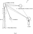
- FIG. 2 discloses an embodiment of the wireless communication network 100 comprising the radio network node 110 and the user equipment 120.
- the radio network node 110 comprises, or is connected to, a multiple antenna array 210; or antenna array as it also may be referred to as, which may be configured for massive MIMO.
- the multiple antenna array 210 comprises multiple antenna elements, such as e.g. 100 antenna elements, just to mention an example.
- the radio network node 110 further comprises a pre-filter 220, for mapping some significant clusters of signals to logical antennas.
- the number of logical antennas may be smaller, or much smaller, than the number of antenna elements comprised in the multiple antenna array 210.
- Signals received in the uplink may be received from the user equipment 120, or from an interferer 230.
- the interferer 230 may comprise another user equipment, or any other arbitrary device configured for transmission of wireless signals.
- Signals received by the radio network node 110 in the uplink from the user equipment 120 and possibly from one or more interferers 230, may be divided into clusters, which clusters are either generating or scattering wireless signals.
- the cluster location may be considered frequency and time invariant, when the cluster is not moving.
- TTIs Transmission Time Intervals
- the cluster When the cluster is moving, it may be considered stationary for at least one or some Transmission Time Intervals (TTIs), which may be approximately e.g. 1, 2, 10, 20, 40 or 80 ms according to different standards and/ or protocols; or some other similar time period comprising a subset, or multiple respectively, of any of the enumerated time periods.
- TTIs Transmission Time Intervals
- the user equipment 120 even when travelling at a rather speedy velocity of 300 m/s (1080 km/h) relative to the radio network node 110, moves approximately a modest 30 cm during one TTI (1 ms in LTE).
- the user equipment 120 may thereby be considered as stationary at least during that TTI, even when travelling at such rather extraordinary high velocity.
- Beamforming and/ or spatial multiplexing may be based on orthogonal propagation paths between the radio network node 110 and the user equipment 120 through these detected and selected clusters, sometimes referred to as rank M of the link.
- the rank M may typically be smaller, or much smaller than the number of antenna elements N comprised in the multiple antenna array 210.
- the rank M may be e.g. approximately 8, 16 or similar.
- the multiple antenna array 210 may comprise at least ten times more antenna elements N than the rank M of the wireless communication network 100; i.e. may comprise e.g. 100 or more antenna elements in some embodiments.
- the dusters may carry any combination of desired signal and interference in some embodiments.
- the rank M of the wireless communication network 100 also may comprise interferers 230.
- Some embodiments may utilise the fact that the received signals on neighbouring elements of the multiple antenna array 210 are correlated. This correlation unveils the Angle of Arrival (AoA) of each individual propagation path arriving at the array.
- the AoA may sometimes be referred to as Direction of Arrival (DoA), or just "direction", of the received uplink signal.
- AoA measurement is a method for determining the direction of propagation of a radiofrequency wave incident on the multiple antennas 210.
- AoA may be determined by measuring the Time Difference of Arrival (TDOA) at individual elements of the multiple antennas 210; and based on these delays the AoA may be calculated.
- TDOA Time Difference of Arrival
- TDOA measurement may comprise measuring the difference in received phase at each element in the multiple antenna array 210. This may be thought of as beamforming in reverse.
- downlink beamforming the signal from each element is delayed by some weight to steer the gain of the antenna array in relation to the particular user equipment 120.
- the delay of arrival at each element may be measured directly and converted to an AoA measurement.
- the number of propagation paths is related to the rank M of the wireless communication network 100, while the angular resolution of the wireless communication network 100 is defined by the number of antenna elements N, and their spacing.
- a spatial analysis and a selection of significant AoAs may be performed, i.e. angles with significant propagation paths, and a mapping of logical antennas to selected significant AoAs is established.
- the set of AoA may also be used for downlink Angle of Departures (AoD) in downlink transmission, in particular in FDD mode.
- AoD Angle of Departures
- Visibility Range of Arrival may be determined.
- the Visibility Range of Arrival is a determination of which antenna elements in the multiple antenna array 210 that actually receives the uplink signal. Due to shading etc., the received signal may be received only on a subset of the antenna elements comprised in the multiple antenna array 210.
- the determined AoA and/ or VRoA differences may be utilised to separate incoming signals spatially.
- VRoA enables an improved separation of uplink signals in comparison with only using AoA.
- another advantage is that transmission of downlink signals intended for the user equipment 120 may be inhibited. It may thereby be avoided that signals are transmitted in vain from antenna elements that are shaded for the user equipment 120, which saves energy and reduces downlink interference for other user equipment within the cell.
- the pre-filter design may be intended to be reused for both uplink reception and downlink transmission, regardless if the directions are separated by time (TDD in TDMA), frequency (FDD in FDMA), code (CDMA) or space, as may be the case in different embodiments.
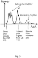
- Figure 3 illustrates a diagram illustrating received pilot signals in an example, as received by the radio network node 110, in an embodiment.
- the radio network node 110 receives a first uplink signal directly from the user equipment 120, a second uplink signal indirectly from the user equipment 120 and an uplink signal from the interferer 230.
- the pre-filter 220 in the radio network node 110 may be configured to block the uplink signals received from the interferer 230. Thereby, the pilot signals from the user equipment 120 may be selected.
- a sparse coordinated orthogonal pilot schedule i.e. a first subset of available pilot resources, for large scale pilot contamination discrimination using the above described spatial pre-filter.
- a dense un-coordinated not-so-orthogonal schedule i.e. a second subset of available pilot resources, not overlapping the first subset of available pilot resources, for small scale fading estimation.
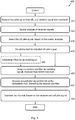
- FIG. 4 is a flow chart illustrating embodiments of a method 400 for use in a radio network node 110, for channel estimation of a channel used for wireless signal communication between a user equipment 120 and the radio network node 110 in a wireless communication system 100.
- the radio network node 110 comprises a multiple antenna array 210 configured for beamforming, spatial multiplexing and MIMO transmission.
- the multiple antenna array 210 may comprise a multitude of antenna elements, mounted at a distance from each other such that at least some of the antenna elements are able to receiving the same signal from the user equipment 120.
- the user equipment 120 may be served by the radio network node 110 in a heterogeneous wireless communication system 100 comprising the radio network node 110 and at least one neighbour network node 130.
- the wireless communication system 100 may be based on 3GPP LTE. Further, the wireless communication system 100 may be based on FDD or TDD in different embodiments.
- the radio network node 110 and/ or the neighbour network node 130 may comprise an evolved NodeB (eNodeB) according to some embodiments.
- eNodeB evolved NodeB
- the method 400 may comprise a number of actions 401-408. It is however to be noted that any, some or all of the described actions 401-408, may be performed in a somewhat different chronological order than the enumeration indcates, be performed simultaneously or even be performed in a completely reversed order according to different embodiments. Also, some actions such as e.g. actions 405 may be performed only within some alternative embodiments. Further, it is to be noted that some actions may be performed in a plurality of alternative manners according to different embodiments, and that some such alternative manners may be performed only within some, but not necessarily all embodiments.
- the method 400 may comprise the following actions:
- a first pilot signal is received from the user equipment 120, and a wireless signal is received from an interferer 230.
- the first pilot signal may be received from the user equipment 120 over the multiple antenna array 210.
- the wireless signals may thus be uplink signals, received directly from the user equipment 120, or may be received indirectly from the user equipment 120 via scattering reflections. Further, the received wireless signals may be received from interferers 230, i.e. other user equipment within range but in another cell, and/ or reflections from signals transmitted by other interferers 230/ user equipment.
- the first pilot signal of the user equipment 120 may be comprised in a set of orthogonal pilot signals coordinated between the radio network node 110 and a neighbour network node 130.
- the first pilot signal of the user equipment 120 may be a Sounding Reference Signal (SRS) and the scheduling of the first pilot signal may be coordinated between the radio network node 110 and the neighbour network node 130.
- SRS Sounding Reference Signal
- the received 401 signals are spatially analysed.
- the spatial analysis of the received 401 signals may comprise a comparison of the received signal strength/ quality with a predetermined threshold value, or a predetermined number of directions in some embodiments.
- the pilot signal received 401 from the user equipment 120 is selected, based on the spatial analysis 402.
- the signals having a signal strength/ quality exceeding the predetermined threshold value may be selected.
- An angle of arrival for the selected 403 pilot signal is determined.
- the AoAs may be determined by measuring the Time Difference of Arrival (TDOA) at individual antenna elements of the multiple antenna array 210, according to some embodiments.
- TDOA Time Difference of Arrival
- This action may be performed within some, but not necessarily all embodiments of the method 400.
- the visibility range of arrival for the selected 403 pilot signal may be determined. Thereby it may be determined which antenna elements that are receiving the uplink signal.
- a receiver pre-filter for isolating signals received 401 from the determined 404 angle of arrival is designed.
- the design of the receiver pre-filter may further be made for isolating pilot signals received 401 from the determined 405 visibility range of arrival in some embodiments.
- the spatial pre-filtering may be regarded as a manipulation of the transmission channel.
- the channel may be regarded as a combination of the radio channel, antenna properties, transmitter properties (Analog and Digital) and the spatial pre-filter.
- the pre-filter may be recalculated continuously, or at a predetermined time interval, such as e.g. every TTI, e.g. approximately every 1, 2, 10, 20, 40 or 80 ms, or some other similar time period.
- a Fast Fourier Transformation (FFT) may be made on the received signals.
- FFT Fast Fourier Transformation
- Acquisition and discrimination of spatial profile may then be made.
- the acquisition may be blind, based on received signal, or based on a model such as a matched filter tuned for known reference signals according to different embodiments.
- Explicit or implicit schedule information used for addressing of a pre-filter database, e.g. pairing received signal streams with transmitted signal streams. Further, a filtering may be made for filtering out weak signals. Thus received signals having a signal strength below a threshold value may be filtered out. The AoA of the remaining, selected signals may then be determined and a receiver pre-filter, for isolating signals received from the determined AoA, may be determined. The other signals/ AoAs may be discarded. Further, a number of M antenna streams may be mapped on Angles of Departure AoDs, possibly adjusted for FDD distance in some embodiments.
- the design of the receiver pre-filter may be based on blind estimations and/ or statistics in some embodiments.
- An advantage of using blind estimations/ statistics may be that any received signals may be utilised for the pre-filtering.
- the design of the receiver pre-filter may be model based, e.g. based on matched filter signal strength measurements on the first pilot signal received 401 from the user equipment 120.
- An advantage of using a matched filter tuned for known reference signals such as pilot signals is that interferers 230 may be filtered out, according to some embodiments. Thereby, an improved signal quality of the signal received in the uplink from the user equipment 120 may be achieved.
- a second pilot signal is received from the user equipment 120 at the determined 404 angle of arrival, filtered by the designed 406 receiver pre-filter.
- the second pilot signal may not be comprised in the set of orthogonal pilot signals coordinated between the radio network node 110 and a neighbour network node 130.
- the second pilot signal of the user equipment 120 may be a demodulation reference signal (DMRS) or an SRS, which is not required to be coordinated between the radio network node 110 and the neighbour network node 130.
- DMRS demodulation reference signal
- SRS SRS
- the channel is estimated, based on the received 405 second pilot signal.
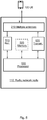
- Figure 5 illustrates an embodiment of a radio network node 110, for channel estimation of a channel used for wireless signal communication between a user equipment 120 and the radio network node 110 in a wireless communication system 100.
- the radio network node 110 comprises a multiple antenna array 210 configured for beamforming, spatial multiplexing and Multiple Input Multiple Output (MIMO) transmission.
- the multiple antenna array 210 may comprise a multitude of antenna elements, mounted at a distance from each other such that at least some of the antenna elements are able to receiving the same signal from the user equipment 120.
- the radio network node 110 is further configured for wireless communication in a wireless communication system 100.
- the first network node 110 is also configured for performing the method 400 according to at least some of the previously described actions 401-408 for channel estimation of a channel used for wireless signal communication between a user equipment 120 and the radio network node 110 in a wireless communication system 100.
- the user equipment 120 may be served by the radio network node 110 in a heterogeneous wireless communication system 100 comprising the radio network node 110 and possibly at least one other neighbour network node 130.
- the wireless communication network 100 may be based on 3GPP LTE. Further, the wireless communication system 100 may be based on FDD or TDD in different embodiments.
- the radio network node 110 and/ or the other neighbour network node 130 may comprise an evolved NodeB (eNodeB) according to some embodiments.
- eNodeB evolved NodeB
- the radio network node 110 comprises a receiver 510, configured for receiving a first pilot signal from the user equipment 120, and a wireless signal from an interferer 230.
- the receiver 510 is also configured for receiving a second pilot signal from the user equipment 120 at a determined angle of arrival, filtered by a receiver pre-filter.
- the first pilot signal of the user equipment 120 may be comprised in a set of orthogonal pilot signals coordinated between the radio network node 110 and a neighbour network node 130 in some embodiments.
- the second pilot signal may not be comprised in the set of orthogonal pilot signals coordinated between the radio network node 110 and a neighbour network node 130.
- the second pilot signal of the user equipment 120 may be a demodulation reference signal, DMRS, or an SRS, which is not required to be coordinated between the radio network node 110 and the neighbour network node 130.
- the first pilot signal of the user equipment 120 may be a Sounding Reference Signal (SRS) and wherein scheduling of the first pilot signal may be coordinated between the radio network node 110 and the neighbour network node 130.
- SRS Sounding Reference Signal
- the radio network node 110 comprises a processor 520 configured for spatial analysing the received signals; and configured for selecting pilot signals from the user equipment 120, based on the spatial analysis.
- the processor 520 is additionally configured for determining an angle of arrival for the selected pilot signals.
- the processor is also configured for designing a receiver pre-filter, for isolating signals received from the determined angle of arrival.
- the processor 520 is also further configured for estimating the channel, based on the received second pilot signal.
- the processor 520 may be further configured for determining visibility range of arrival for the selected signals.
- the processor 520 may be configured for designing the receiver pre-filter by isolating pilot signals received from the determined visibility range of arrival.
- the design of the receiver pre-filter may be based on blind estimations and/ or statistics. Further, the design of the receiver pre-filter may be model based in some embodiments, e.g. based on matched filter signal strength measurements on the first pilot signal received from the user equipment 120.
- the processor 520 may also be configured for spatial analysing the received signals by comparing the received signal strength with a predetermined threshold value, and may in further addition be configured for selecting the signals having a signal strength exceeding the predetermined threshold value.
- Such processor 520 may comprise one or more instances of a processing circuit, i.e. a Central Processing Unit (CPU), a processing unit, a processing circuit, a processor, an Application Specific Integrated Circuit (ASIC), a microprocessor, or other processing logic that may interpret and execute instructions.
- a processing circuit i.e. a Central Processing Unit (CPU), a processing unit, a processing circuit, a processor, an Application Specific Integrated Circuit (ASIC), a microprocessor, or other processing logic that may interpret and execute instructions.
- CPU Central Processing Unit
- ASIC Application Specific Integrated Circuit
- microprocessor may thus represent a processing circuitry comprising a plurality of processing circuits, such as, e.g., any, some or all of the ones enumerated above.
- the radio network node 110 may further comprise at least one memory 525, according to some embodiments.
- the optional memory 525 may comprise a physical device utilised to store data or a program, i.e., a sequence of instructions, on a temporary or permanent basis.
- the memory 525 may comprise integrated circuits comprising silicon-based transistors. Further, the memory 525 may be volatile or non-volatile.
- a computer program comprising program code may perform a method 400 according to any, at least some, or all of the functions of the actions 401-408 for channel estimation of a channel used for wireless signal communication between a user equipment 120 and the radio network node 110 in a wireless communication system 100, which radio network node 110 comprises a multiple antenna array 210 configured for beamforming, spatial multiplexing and Multiple Input Multiple Output (MIMO) transmission.
- MIMO Multiple Input Multiple Output
- the program code comprises instructions for executing a method 400 that comprises receiving 401 a first pilot signal from the user equipment 120, and a wireless signal from an interferer 230.
- the method 400 may also comprise spatial analysing 402 the received 401 signals.
- the method 400 comprises selecting 403 pilot signals from the user equipment 120, based on the spatial analysis 402.
- the method 400 comprises determining 404 an angle of arrival for the selected 403 pilot signals.
- the method 400 further comprises designing 406 a receiver pre-filter, for isolating signals received 401 from the determined 404 angle of arrival.
- the method 400 also comprises receiving 407 a second pilot signal from the user equipment 120 at the determined 404 angle of arrival, filtered by the designed 406 receiver pre-filter.
- the method 400 also comprises estimating 408 the channel, based on the received 405 second pilot signal.
- the method 400 may be performed when the program code is loaded into the processor 520 in the radio network node 110.
- the computer program product mentioned above may be provided for instance in the form of a data carrier carrying computer program code for performing at least some of the actions 401-408 according to some embodiments when being loaded into the processor 520.
- the data carrier may be, e.g., a hard disk, a CD ROM disc, a memory stick, an optical storage device, a magnetic storage device or any other appropriate medium such as a disk or tape that may hold machine readable data in a non transitory manner.
- the computer program product may furthermore be provided as computer program code on a server and downloaded to the first network node 110 remotely, e.g., over an Internet or an intranet connection.
- a coordinated multipoint scheme for orthogonal pilot signal scheduling between a plurality of neighbour radio network nodes 110, 130 in a wireless communication system 100 is provided.
- the coordinated multipoint scheme for orthogonal pilot signal scheduling may comprise a first subset of orthogonal pilot signals, to be used for spatial analysis by the radio network nodes 110, 130.
- the coordinated multipoint scheme for orthogonal pilot signal scheduling may comprise a second subset of pilot signals, where each comprised pilot signal is distinct from any pilot signal comprised in the first subset of orthogonal pilot signals, to be used for channel estimation by the radio network nodes 110, 130.
- the term “and/ or” comprises any and all combinations of one or more of the associated listed items.
- the singular forms “a”, “an” and “the” are to be interpreted as “at least one”, thus also possibly comprising a plurality of entities of the same kind, unless expressly stated otherwise.
- the terms “includes”, “comprises”, “including” and/ or “comprising” specifies the presence of stated features, actions, integers, steps, operations, elements, and/ or components, but do not preclude the presence or addition of one or more other features, actions, integers, steps, operations, elements, components, and/ or groups thereof.
- a single unit such as e.g.
- a processor may fulfil the functions of several items recited in the claims.
- a computer program may be stored/ distributed on a suitable medium, such as an optical storage medium or a solid-state medium supplied together with or as part of other hardware, but may also be distributed in other forms such as via Internet or other wired or wireless communication system.
Landscapes
- Engineering & Computer Science (AREA)
- Signal Processing (AREA)
- Computer Networks & Wireless Communication (AREA)
- Power Engineering (AREA)
- Physics & Mathematics (AREA)
- Mathematical Physics (AREA)
- Quality & Reliability (AREA)
- Mobile Radio Communication Systems (AREA)
- Radio Transmission System (AREA)
Claims (11)
- Funknetzknoten (110), zur Kanalschätzung eines Kanals, der zur drahtlosen Signalkommunikation zwischen einem Benutzergerät (120) und dem Funknetzknoten (110) in einem drahtlosen Kommunikationssystem (100) verwendet wird, wobei der Funknetzknoten (110) eine Mehrfachantennenanordnung (210) umfasst, die für Strahlformung, räumliches Multiplexing und Übertragung mit Multiple Input Multiple Output, MIMO, konfiguriert ist, wobei der Funknetzknoten (110) ferner Folgendes umfasst:einen Empfänger (510), der zum Empfangen eines ersten Überwachungssignals des Benutzergeräts (120), und eines drahtlosen Signals von einem Störer (230) konfiguriert ist; undauch zum Empfangen eines zweiten Überwachungssignals von dem Benutzergerät (120) in einem ermittelten Einfallswinkel konfiguriert ist, der durch einen Empfängervorfilter gefiltert wurde; undeinen Prozessor (520), der zum räumlichen Analysieren des empfangenen ersten Überwachungssignals konfiguriert ist; undzum Auswählen des ersten Überwachungssignals aus dem Benutzergerät (120) basierend auf der räumlichen Analyse konfiguriert ist; undzusätzlich zum Ermitteln eines Einfallswinkels für das ausgewählte erste Überwachungssignal konfiguriert ist; undferner zum Entwerfen des Empfängervorfilters, zum Isolieren des ersten Überwachungssignals, das von dem ermittelten Einfallswinkel empfangen wird, konfiguriert ist; undferner auch zum Abschätzen des Kanals, basierend auf dem empfangenen zweiten Überwachungssignal, konfiguriert ist;wobei das erste Überwachungssignal des Benutzergeräts (120) in einem Satz von orthogonalen Überwachungssignalen enthalten ist, die zwischen dem Funknetzknoten (110) und einem benachbarten Netzknoten (130) abgestimmt sind, und das zweite Überwachungssignal nicht in dem Satz von orthogonalen Überwachungssignalen enthalten ist, die zwischen dem Funknetzknoten (110) und dem benachbarten Netzknoten (130) abgestimmt sind.
- Funknetzknoten (110) nach Anspruch 1, wobei der Prozessor (520) auch zum Ermitteln des Sichtbarkeitsbereichs der Ankunft für die ausgewählten Signale konfiguriert ist; und
auch zum Entwerfen des Empfängervorfilters durch Isolieren von Überwachungssignalen, die von dem ermittelten Sichtbarkeitsbereich der Ankunft empfangen werden, konfiguriert ist. - Funknetzknoten (110) nach einem der Ansprüche 1 oder 2, wobei der Prozessor (520) auch zum räumlichen Analysieren der empfangenen Signale durch Vergleichen der empfangenen Signalstärke mit einem vorermittelten Schwellenwert konfiguriert ist, und auch zum Auswählen der Signale mit einer Signalstärke, die den vorermittelten Schwellenwert überschreitet, konfiguriert ist.
- Funknetzknoten (110) nach einem der vorangehenden Ansprüche, wobei das erste Überwachungssignal des Benutzergeräts (120) ein Klangreferenzsignal, SRS, ist, und wobei die Planung des ersten Überwachungssignals zwischen dem Funknetzknoten (110) und dem benachbarten Netzknoten (130) abgestimmt ist; und
wobei das zweite Überwachungssignal des Benutzergeräts (120) ein Demodulationsreferenzsignal, DMRS oder ein SRS ist, das nicht zwischen dem Funknetzknoten (110) und dem benachbarten Netzknoten (130) abgestimmt sein muss. - Funknetzknoten (110) nach einem der vorangehenden Ansprüche, wobei das Design des Empfängervorfilters auf Blindabschätzungen und/oder Statistiken basiert.
- Funknetzknoten (110) nach einem der vorangehenden Ansprüche, wobei der Entwurf des Empfängervorfilters modellbasiert ist, z. B. basierend auf Messungen der Stärke des angepassten Filtersignals an dem ersten Überwachungssignal, das von dem Benutzergerät (120) empfangen wird.
- Funknetzknoten (110) nach einem der vorangehenden Ansprüche, wobei die Mehrfachantennenanordnung (210) eine Vielzahl von Antennenelementen umfasst, die in einem Abstand voneinander so montiert sind, dass mindestens einige der Antennenelemente in der Lage sind, das gleiche Signal von dem Benutzergerät (120) zu empfangen.
- Funknetzknoten (110) nach einem der vorangehenden Ansprüche, wobei der Funknetzknoten (110) einen entwickelten NodeB, eNodeB umfasst; und
wobei das drahtlose Kommunikationsnetzwerk (100) auf dem 3rd Generation Partnership Project Long Term Evolution, 3GPP LTE, basiert. - Verfahren (400) in einem Funknetzknoten (110) zum Kanalschätzen eines Kanals, der für die drahtlose Signalkommunikation zwischen einem Benutzergerät (120) und dem Funknetzknoten (110) in einem drahtlosen Kommunikationssystem (100) verwendet wird, wobei der Funknetzknoten (110) eine Mehrfachantennenanordnung (210) umfasst, die für die Strahlformung, das räumliche Multiplexing und die Übertragung mit Multiple Input Multiple Output, MIMO konfiguriert ist, das Verfahren (400) Folgendes umfassend:Empfangen (401) eines ersten Überwachungssignals von dem Benutzergerät (120), und eines drahtlosen Signals von einem Störer (230);räumliches Analysieren (402) des empfangenen (401) ersten Überwachungssignals;Auswählen (403) des ersten Überwachungssignals von dem Benutzergerät (120) basierend auf der räumlichen Analyse (402);Ermitteln (404) eines Einfallswinkels für das ausgewählte (403) erste Überwachungssignal;Entwerfen (406) eines Empfängervorfilters zum Isolieren des ersten, von dem ermittelten (404) Einfallswinkel empfangenen Überwachungssignals (401);Empfangen (407) eines zweiten Überwachungssignals von dem Benutzergerät (120) unter dem ermittelten (404) Einfallswinkel, gefiltert durch den entworfenen (406) Empfängervorfilter; undSchätzen (408) des Kanals, basierend auf dem empfangenen (405) zweiten Überwachungssignal;wobei das erste Überwachungssignal des Benutzergeräts (120) in einem Satz von orthogonalen Überwachungssignalen umfasst ist, die zwischen dem Funknetzknoten (110) und einem benachbarten Netzknoten (130) abgestimmt sind, und das zweite Überwachungssignal nicht in dem Satz von orthogonalen Überwachungssignalen umfasst ist, die zwischen dem Funknetzknoten (110) und dem benachbarten Netzknoten (130) abgestimmt sind.
- Verfahren (400) nach Anspruch 9, ferner Folgendes umfassend:Ermitteln (405) des Sichtbarkeitsbereichs der Ankunft für das ausgewählte (403) Überwachungssignal; undwobei der Entwurf (406) des Empfangsvorfilters ferner zum Isolieren der empfangenen Überwachungssignale (401) aus dem ermittelten (405) Sichtbarkeitsbereich der Ankunft ausgebildet ist.
- Computerprogrammprodukt, umfassend ein computerlesbares Speichermedium, auf dem Programmcode gespeichert ist, zur Verwendung durch einen Funknetzknoten (110) zur Kanalschätzung eines Kanals, der für die drahtlose Signalübertragung zwischen einem Benutzergerät (120) und dem Funknetzknoten (110) in einem drahtlosen Kommunikationssystem (100) verwendet wird, wobei der Funknetzknoten (110) eine Mehrfachantennenanordnung (210) umfasst, die für die Strahlformung, das räumliche Multiplexing und die Übertragung mit Multiple Input Multiple Output, MIMO, konfiguriert ist, wobei der Programmcode Anweisungen umfasst, die, wenn sie durch den Funknetzknoten (110) ausgeführt werden, den Netzwerkknoten (110) veranlassen, das Verfahren (400) nach Anspruch 9 oder 10 auszuführen.
Applications Claiming Priority (1)
| Application Number | Priority Date | Filing Date | Title |
|---|---|---|---|
| PCT/EP2014/059401 WO2015169358A1 (en) | 2014-05-08 | 2014-05-08 | Channel estimation in wireless communication network node |
Publications (2)
| Publication Number | Publication Date |
|---|---|
| EP3132580A1 EP3132580A1 (de) | 2017-02-22 |
| EP3132580B1 true EP3132580B1 (de) | 2020-01-08 |
Family
ID=50685922
Family Applications (1)
| Application Number | Title | Priority Date | Filing Date |
|---|---|---|---|
| EP14722667.4A Active EP3132580B1 (de) | 2014-05-08 | 2014-05-08 | Kanalschätzung in einem drahtloskommunikationssystemknoten |
Country Status (7)
| Country | Link |
|---|---|
| US (1) | US10212715B2 (de) |
| EP (1) | EP3132580B1 (de) |
| JP (1) | JP6393782B2 (de) |
| KR (1) | KR101941051B1 (de) |
| CN (1) | CN106233684B (de) |
| ES (1) | ES2769589T3 (de) |
| WO (1) | WO2015169358A1 (de) |
Families Citing this family (23)
| Publication number | Priority date | Publication date | Assignee | Title |
|---|---|---|---|---|
| CN105406950A (zh) | 2014-08-07 | 2016-03-16 | 索尼公司 | 用于无线通信的装置和方法、电子设备及其方法 |
| WO2016155758A1 (en) * | 2015-03-27 | 2016-10-06 | Telefonaktiebolaget Lm Ericsson (Publ) | Methods and arrangements for mitigating inter-cluster interference |
| US10045352B2 (en) * | 2016-01-13 | 2018-08-07 | Futurewei Technologies, Inc. | Channel estimation in large scale MIMO systems using iterative location based spatial filtering |
| CN105634571B (zh) * | 2016-01-18 | 2018-12-28 | 重庆邮电大学 | 大规模mimo系统中基于部分导频复用的导频污染减轻方法 |
| WO2017137059A1 (en) * | 2016-02-08 | 2017-08-17 | Sony Mobile Communications Inc. | Operating a cellular mimo system |
| CN110855586B (zh) * | 2016-07-08 | 2022-08-26 | 北京紫光展锐通信技术有限公司 | 导频信号传输方法 |
| EP3586470A4 (de) * | 2017-02-24 | 2021-03-10 | AMI Research & Development, LLC | Gerichtete mimo-antenne |
| US11172488B2 (en) * | 2017-03-08 | 2021-11-09 | Telefonaktiebolaget Lm Ericsson (Publ) | Power amplifier-aware user scheduling |
| CN106972907B (zh) * | 2017-03-23 | 2019-05-03 | 北京工业大学 | 大规模天线系统信道训练及传输过程小区间干扰消除方法 |
| CN107070624B (zh) * | 2017-03-23 | 2020-03-31 | 东南大学 | 一种基于大尺度衰落和多路径到达角的多用户导频调度方法 |
| CN106817191A (zh) * | 2017-03-27 | 2017-06-09 | 成都凯力科技有限公司 | 干扰消除方法 |
| CN110312304A (zh) * | 2018-03-27 | 2019-10-08 | 华为技术有限公司 | 控制方法、装置及无线访问点 |
| EP3570578B1 (de) * | 2018-05-15 | 2021-12-22 | Volkswagen Aktiengesellschaft | Vorrichtung, verfahren und computerprogramm zur bestimmung von informationen im zusammenhang mit der echtheit einer drahtlosen nachricht in einer drahtlosen gruppenkommunikation zwischen fahrzeugen einer fahrzeuggruppe |
| WO2020069333A1 (en) | 2018-09-28 | 2020-04-02 | Sony Corporation | Method and system for managing interference in multi trp systems |
| EP3868048A4 (de) * | 2018-10-19 | 2022-05-25 | Telefonaktiebolaget Lm Ericsson (Publ) | Verfahren, drahtlose vorrichtung und netzwerkknoten zur kommunikation in einem drahtlosen netzwerk |
| CN109639378B (zh) * | 2019-01-29 | 2021-06-01 | 南京信息工程大学 | 矩形隧道无线传播信道建模方法 |
| US11902957B2 (en) | 2019-02-13 | 2024-02-13 | Telefonaktiebolaget Lm Ericsson (Publ) | Multi-user coordinated transmission in cellular systems |
| KR102728798B1 (ko) | 2020-02-25 | 2024-11-11 | 삼성전자주식회사 | 무선 통신 장치 및 이의 채널 추정 방법 |
| CN111371540B (zh) * | 2020-03-19 | 2022-05-27 | 东北电力大学 | 基于用户分组的大规模mimo系统导频分配方法 |
| CN115603786B (zh) * | 2021-07-09 | 2025-03-14 | 华为技术有限公司 | 信号发射方法及无线通信装置 |
| CN114499651B (zh) * | 2021-12-30 | 2025-01-21 | 中国电子科技集团公司第五十四研究所 | 信号传输方法、信号传输装置及电子设备 |
| JP7564140B2 (ja) * | 2022-02-18 | 2024-10-08 | 株式会社Kddi総合研究所 | 無線通信における高精度なチャネル推定を実行する制御装置、制御方法、及びプログラム |
| US12562788B2 (en) | 2024-06-28 | 2026-02-24 | Tarana Wireless, Inc. | Systems and methods for spatial compatibility determination and weight generation using beamformed sounding signals |
Family Cites Families (31)
| Publication number | Priority date | Publication date | Assignee | Title |
|---|---|---|---|---|
| FI105430B (fi) | 1995-05-24 | 2000-08-15 | Nokia Networks Oy | Tukiasemalaitteisto sekä menetelmä antennikeilan suuntaamiseksi |
| US5694133A (en) * | 1996-02-05 | 1997-12-02 | Ghose; Rabindra N. | Adaptive direction finding system |
| US5933421A (en) * | 1997-02-06 | 1999-08-03 | At&T Wireless Services Inc. | Method for frequency division duplex communications |
| US6147640A (en) * | 1999-03-16 | 2000-11-14 | Hughes Electronics Corporation | Communications satellite interference location system |
| FI20000476A0 (fi) * | 2000-03-01 | 2000-03-01 | Nokia Networks Oy | Menetelmä radioyhteyden toiminnan parantamiseksi |
| GB0018859D0 (en) * | 2000-08-01 | 2000-09-20 | Fujitsu Ltd | Apparatus for and method of receiving a transmission signal |
| JP3730194B2 (ja) * | 2002-04-05 | 2005-12-21 | 株式会社国際電気通信基礎技術研究所 | アレーアンテナの制御方法、受信信号の信号対雑音比の計算方法及び無線受信機の適応制御方法 |
| US7057573B2 (en) | 2001-11-07 | 2006-06-06 | Advanced Telecommuications Research Institute International | Method for controlling array antenna equipped with a plurality of antenna elements, method for calculating signal to noise ratio of received signal, and method for adaptively controlling radio receiver |
| US7373127B2 (en) * | 2005-04-27 | 2008-05-13 | Delphi Technologies, Inc. | Digital beam forming for communications systems |
| US8233554B2 (en) * | 2010-03-29 | 2012-07-31 | Eices Research, Inc. | Increased capacity communications for OFDM-based wireless communications systems/methods/devices |
| KR100976502B1 (ko) * | 2005-09-28 | 2010-08-18 | 엘지전자 주식회사 | 협력 중계를 이용하여 셀룰러 네트워크 내에서 데이터를전송하는 방법 |
| JP4847540B2 (ja) | 2005-11-29 | 2011-12-28 | テレフオンアクチーボラゲット エル エム エリクソン(パブル) | 無線マルチホップ中継ネットワークにおけるスケジューリング |
| US20070147536A1 (en) * | 2005-12-27 | 2007-06-28 | Ezer Melzer | Wireless communication device employing interference-sensitive mode selection and associated methods |
| US20070160156A1 (en) * | 2006-01-09 | 2007-07-12 | Ezer Melzer | Wireless communication device employing interference-sensitive mode selection and associated methods |
| US8374132B2 (en) | 2006-05-29 | 2013-02-12 | Kyocera Corporation | Base station device, method for controlling base station device, receiving device, adaptation algorithm control method, radio communication device, and radio communication method |
| JP5075359B2 (ja) * | 2006-05-29 | 2012-11-21 | 京セラ株式会社 | 基地局装置及びその制御方法 |
| JP4481336B2 (ja) * | 2008-02-27 | 2010-06-16 | 京セラ株式会社 | チャネル情報予測システム及びチャネル情報予測方法 |
| GB0820535D0 (en) | 2008-11-10 | 2008-12-17 | Icera Inc | Communication system and method |
| US8599976B2 (en) * | 2009-03-16 | 2013-12-03 | Marvell World Trade Ltd. | Multi-user multiple input multiple output (MU-MIMO) receiver |
| US8494073B2 (en) * | 2009-07-14 | 2013-07-23 | Cisco Technology, Inc. | Beamforming weight estimation using wideband multipath direction of arrival analysis |
| IL206417A (en) * | 2010-06-16 | 2016-06-30 | Elta Systems Ltd | Spatial Reset System and Methods in a Multichannel Communication System |
| US8626214B2 (en) | 2010-06-22 | 2014-01-07 | Alcatel Lucent | Method of cancelling interference in sounding reference signals |
| JP2012181052A (ja) * | 2011-02-28 | 2012-09-20 | Toshiba Corp | 相関抑圧フィルタ、ウェイト算出方法、ウェイト算出装置、アダプティブアレーアンテナ及びレーダ装置 |
| US8837621B2 (en) * | 2011-05-09 | 2014-09-16 | Telefonaktiebolaget L M Ericsson (Publ) | Channel estimation for a very large-scale multiple-input multiple output (MIMO) system |
| KR101652216B1 (ko) * | 2011-06-29 | 2016-08-29 | 후지쯔 가부시끼가이샤 | 간섭층들의 표시를 위한 다운링크 제어 시그널링 |
| JP6179009B2 (ja) | 2012-09-20 | 2017-08-16 | シャープ株式会社 | 端末装置、基地局装置、無線通信方法、および集積回路 |
| WO2014074055A2 (en) * | 2012-11-12 | 2014-05-15 | Telefonaktiebolaget L M Ericsson (Publ) | Transmission mode selection and downlink scheduling using primary and dedicated pilot signals |
| US9774416B2 (en) * | 2013-01-25 | 2017-09-26 | Ntt Docomo, Inc. | Mobile communication terminal |
| US9651652B2 (en) * | 2013-02-07 | 2017-05-16 | L3 Technologies, Inc. | Interference cancellation system for location and direction finding |
| US20160204919A1 (en) * | 2013-08-20 | 2016-07-14 | Telefonaktiebolaget L M Ericsson (Publ) | Method and Controlling Node for Controlling Radio Communication in a Cellular Network |
| US9729234B2 (en) * | 2015-06-22 | 2017-08-08 | The Boeing Company | Free space optical communications network with bent pipe channel and pilot channel |
-
2014
- 2014-05-08 EP EP14722667.4A patent/EP3132580B1/de active Active
- 2014-05-08 CN CN201480078198.3A patent/CN106233684B/zh active Active
- 2014-05-08 JP JP2016566948A patent/JP6393782B2/ja active Active
- 2014-05-08 ES ES14722667T patent/ES2769589T3/es active Active
- 2014-05-08 WO PCT/EP2014/059401 patent/WO2015169358A1/en not_active Ceased
- 2014-05-08 KR KR1020167033960A patent/KR101941051B1/ko active Active
-
2016
- 2016-11-08 US US15/345,633 patent/US10212715B2/en active Active
Non-Patent Citations (1)
| Title |
|---|
| None * |
Also Published As
| Publication number | Publication date |
|---|---|
| CN106233684B (zh) | 2019-11-29 |
| JP6393782B2 (ja) | 2018-09-19 |
| EP3132580A1 (de) | 2017-02-22 |
| US20170079051A1 (en) | 2017-03-16 |
| US10212715B2 (en) | 2019-02-19 |
| ES2769589T3 (es) | 2020-06-26 |
| KR101941051B1 (ko) | 2019-04-12 |
| WO2015169358A1 (en) | 2015-11-12 |
| CN106233684A (zh) | 2016-12-14 |
| KR20170002553A (ko) | 2017-01-06 |
| JP2017520150A (ja) | 2017-07-20 |
Similar Documents
| Publication | Publication Date | Title |
|---|---|---|
| US10212715B2 (en) | Channel estimation in wireless communication network node | |
| US12284125B2 (en) | System and method for communicating time and frequency tracking signals using configurations for one port CSI-RSs | |
| CN109644109B (zh) | 适应于无线通信系统中的延迟展宽改变 | |
| US10327106B2 (en) | Method and apparatus for estimating position in a wireless communication system | |
| US10375674B2 (en) | Architecture and method in a wireless communication network | |
| US10270569B2 (en) | Method and node in a wireless communication network | |
| WO2014183803A1 (en) | Methods and nodes in a wireless communication network | |
| CN114175718A (zh) | 一种传输信道状态信息的方法及装置 | |
| JP6620820B2 (ja) | 送信パターン構成および信号検出のための方法および装置 | |
| EP2680517A1 (de) | Kanalstreuungsschätzung | |
| WO2015036012A1 (en) | Method and node in a wireless communication system | |
| WO2017171828A1 (en) | Methods and devices for channel estimation | |
| CN119835776A (zh) | 信号配置方法、网络设备、用户设备和中间节点设备 | |
| HK40114215A (zh) | 利用单端口csi-rs配置传输时间和频率跟踪信号的系统和方法 |
Legal Events
| Date | Code | Title | Description |
|---|---|---|---|
| STAA | Information on the status of an ep patent application or granted ep patent |
Free format text: STATUS: THE INTERNATIONAL PUBLICATION HAS BEEN MADE |
|
| PUAI | Public reference made under article 153(3) epc to a published international application that has entered the european phase |
Free format text: ORIGINAL CODE: 0009012 |
|
| STAA | Information on the status of an ep patent application or granted ep patent |
Free format text: STATUS: REQUEST FOR EXAMINATION WAS MADE |
|
| 17P | Request for examination filed |
Effective date: 20161115 |
|
| AK | Designated contracting states |
Kind code of ref document: A1 Designated state(s): AL AT BE BG CH CY CZ DE DK EE ES FI FR GB GR HR HU IE IS IT LI LT LU LV MC MK MT NL NO PL PT RO RS SE SI SK SM TR |
|
| AX | Request for extension of the european patent |
Extension state: BA ME |
|
| RIN1 | Information on inventor provided before grant (corrected) |
Inventor name: SIHLBOM, BJOERN |
|
| DAX | Request for extension of the european patent (deleted) | ||
| STAA | Information on the status of an ep patent application or granted ep patent |
Free format text: STATUS: EXAMINATION IS IN PROGRESS |
|
| 17Q | First examination report despatched |
Effective date: 20181108 |
|
| GRAP | Despatch of communication of intention to grant a patent |
Free format text: ORIGINAL CODE: EPIDOSNIGR1 |
|
| STAA | Information on the status of an ep patent application or granted ep patent |
Free format text: STATUS: GRANT OF PATENT IS INTENDED |
|
| INTG | Intention to grant announced |
Effective date: 20190717 |
|
| GRAS | Grant fee paid |
Free format text: ORIGINAL CODE: EPIDOSNIGR3 |
|
| GRAA | (expected) grant |
Free format text: ORIGINAL CODE: 0009210 |
|
| STAA | Information on the status of an ep patent application or granted ep patent |
Free format text: STATUS: THE PATENT HAS BEEN GRANTED |
|
| AK | Designated contracting states |
Kind code of ref document: B1 Designated state(s): AL AT BE BG CH CY CZ DE DK EE ES FI FR GB GR HR HU IE IS IT LI LT LU LV MC MK MT NL NO PL PT RO RS SE SI SK SM TR |
|
| REG | Reference to a national code |
Ref country code: GB Ref legal event code: FG4D |
|
| REG | Reference to a national code |
Ref country code: CH Ref legal event code: EP |
|
| REG | Reference to a national code |
Ref country code: DE Ref legal event code: R096 Ref document number: 602014059652 Country of ref document: DE |
|
| REG | Reference to a national code |
Ref country code: IE Ref legal event code: FG4D |
|
| REG | Reference to a national code |
Ref country code: AT Ref legal event code: REF Ref document number: 1224077 Country of ref document: AT Kind code of ref document: T Effective date: 20200215 |
|
| REG | Reference to a national code |
Ref country code: NL Ref legal event code: MP Effective date: 20200108 |
|
| REG | Reference to a national code |
Ref country code: ES Ref legal event code: FG2A Ref document number: 2769589 Country of ref document: ES Kind code of ref document: T3 Effective date: 20200626 |
|
| REG | Reference to a national code |
Ref country code: LT Ref legal event code: MG4D |
|
| PG25 | Lapsed in a contracting state [announced via postgrant information from national office to epo] |
Ref country code: NO Free format text: LAPSE BECAUSE OF FAILURE TO SUBMIT A TRANSLATION OF THE DESCRIPTION OR TO PAY THE FEE WITHIN THE PRESCRIBED TIME-LIMIT Effective date: 20200408 Ref country code: NL Free format text: LAPSE BECAUSE OF FAILURE TO SUBMIT A TRANSLATION OF THE DESCRIPTION OR TO PAY THE FEE WITHIN THE PRESCRIBED TIME-LIMIT Effective date: 20200108 Ref country code: LT Free format text: LAPSE BECAUSE OF FAILURE TO SUBMIT A TRANSLATION OF THE DESCRIPTION OR TO PAY THE FEE WITHIN THE PRESCRIBED TIME-LIMIT Effective date: 20200108 Ref country code: PT Free format text: LAPSE BECAUSE OF FAILURE TO SUBMIT A TRANSLATION OF THE DESCRIPTION OR TO PAY THE FEE WITHIN THE PRESCRIBED TIME-LIMIT Effective date: 20200531 Ref country code: FI Free format text: LAPSE BECAUSE OF FAILURE TO SUBMIT A TRANSLATION OF THE DESCRIPTION OR TO PAY THE FEE WITHIN THE PRESCRIBED TIME-LIMIT Effective date: 20200108 Ref country code: RS Free format text: LAPSE BECAUSE OF FAILURE TO SUBMIT A TRANSLATION OF THE DESCRIPTION OR TO PAY THE FEE WITHIN THE PRESCRIBED TIME-LIMIT Effective date: 20200108 |
|
| PG25 | Lapsed in a contracting state [announced via postgrant information from national office to epo] |
Ref country code: GR Free format text: LAPSE BECAUSE OF FAILURE TO SUBMIT A TRANSLATION OF THE DESCRIPTION OR TO PAY THE FEE WITHIN THE PRESCRIBED TIME-LIMIT Effective date: 20200409 Ref country code: HR Free format text: LAPSE BECAUSE OF FAILURE TO SUBMIT A TRANSLATION OF THE DESCRIPTION OR TO PAY THE FEE WITHIN THE PRESCRIBED TIME-LIMIT Effective date: 20200108 Ref country code: LV Free format text: LAPSE BECAUSE OF FAILURE TO SUBMIT A TRANSLATION OF THE DESCRIPTION OR TO PAY THE FEE WITHIN THE PRESCRIBED TIME-LIMIT Effective date: 20200108 Ref country code: IS Free format text: LAPSE BECAUSE OF FAILURE TO SUBMIT A TRANSLATION OF THE DESCRIPTION OR TO PAY THE FEE WITHIN THE PRESCRIBED TIME-LIMIT Effective date: 20200508 Ref country code: SE Free format text: LAPSE BECAUSE OF FAILURE TO SUBMIT A TRANSLATION OF THE DESCRIPTION OR TO PAY THE FEE WITHIN THE PRESCRIBED TIME-LIMIT Effective date: 20200108 Ref country code: BG Free format text: LAPSE BECAUSE OF FAILURE TO SUBMIT A TRANSLATION OF THE DESCRIPTION OR TO PAY THE FEE WITHIN THE PRESCRIBED TIME-LIMIT Effective date: 20200408 |
|
| REG | Reference to a national code |
Ref country code: DE Ref legal event code: R097 Ref document number: 602014059652 Country of ref document: DE |
|
| PG25 | Lapsed in a contracting state [announced via postgrant information from national office to epo] |
Ref country code: RO Free format text: LAPSE BECAUSE OF FAILURE TO SUBMIT A TRANSLATION OF THE DESCRIPTION OR TO PAY THE FEE WITHIN THE PRESCRIBED TIME-LIMIT Effective date: 20200108 Ref country code: CZ Free format text: LAPSE BECAUSE OF FAILURE TO SUBMIT A TRANSLATION OF THE DESCRIPTION OR TO PAY THE FEE WITHIN THE PRESCRIBED TIME-LIMIT Effective date: 20200108 Ref country code: SM Free format text: LAPSE BECAUSE OF FAILURE TO SUBMIT A TRANSLATION OF THE DESCRIPTION OR TO PAY THE FEE WITHIN THE PRESCRIBED TIME-LIMIT Effective date: 20200108 Ref country code: EE Free format text: LAPSE BECAUSE OF FAILURE TO SUBMIT A TRANSLATION OF THE DESCRIPTION OR TO PAY THE FEE WITHIN THE PRESCRIBED TIME-LIMIT Effective date: 20200108 Ref country code: DK Free format text: LAPSE BECAUSE OF FAILURE TO SUBMIT A TRANSLATION OF THE DESCRIPTION OR TO PAY THE FEE WITHIN THE PRESCRIBED TIME-LIMIT Effective date: 20200108 Ref country code: SK Free format text: LAPSE BECAUSE OF FAILURE TO SUBMIT A TRANSLATION OF THE DESCRIPTION OR TO PAY THE FEE WITHIN THE PRESCRIBED TIME-LIMIT Effective date: 20200108 |
|
| PLBE | No opposition filed within time limit |
Free format text: ORIGINAL CODE: 0009261 |
|
| STAA | Information on the status of an ep patent application or granted ep patent |
Free format text: STATUS: NO OPPOSITION FILED WITHIN TIME LIMIT |
|
| REG | Reference to a national code |
Ref country code: AT Ref legal event code: MK05 Ref document number: 1224077 Country of ref document: AT Kind code of ref document: T Effective date: 20200108 |
|
| 26N | No opposition filed |
Effective date: 20201009 |
|
| PG25 | Lapsed in a contracting state [announced via postgrant information from national office to epo] |
Ref country code: IT Free format text: LAPSE BECAUSE OF FAILURE TO SUBMIT A TRANSLATION OF THE DESCRIPTION OR TO PAY THE FEE WITHIN THE PRESCRIBED TIME-LIMIT Effective date: 20200108 Ref country code: AT Free format text: LAPSE BECAUSE OF FAILURE TO SUBMIT A TRANSLATION OF THE DESCRIPTION OR TO PAY THE FEE WITHIN THE PRESCRIBED TIME-LIMIT Effective date: 20200108 Ref country code: LI Free format text: LAPSE BECAUSE OF NON-PAYMENT OF DUE FEES Effective date: 20200531 Ref country code: CH Free format text: LAPSE BECAUSE OF NON-PAYMENT OF DUE FEES Effective date: 20200531 Ref country code: MC Free format text: LAPSE BECAUSE OF FAILURE TO SUBMIT A TRANSLATION OF THE DESCRIPTION OR TO PAY THE FEE WITHIN THE PRESCRIBED TIME-LIMIT Effective date: 20200108 |
|
| PG25 | Lapsed in a contracting state [announced via postgrant information from national office to epo] |
Ref country code: PL Free format text: LAPSE BECAUSE OF FAILURE TO SUBMIT A TRANSLATION OF THE DESCRIPTION OR TO PAY THE FEE WITHIN THE PRESCRIBED TIME-LIMIT Effective date: 20200108 Ref country code: SI Free format text: LAPSE BECAUSE OF FAILURE TO SUBMIT A TRANSLATION OF THE DESCRIPTION OR TO PAY THE FEE WITHIN THE PRESCRIBED TIME-LIMIT Effective date: 20200108 |
|
| REG | Reference to a national code |
Ref country code: BE Ref legal event code: MM Effective date: 20200531 |
|
| GBPC | Gb: european patent ceased through non-payment of renewal fee |
Effective date: 20200508 |
|
| PG25 | Lapsed in a contracting state [announced via postgrant information from national office to epo] |
Ref country code: LU Free format text: LAPSE BECAUSE OF NON-PAYMENT OF DUE FEES Effective date: 20200508 |
|
| PG25 | Lapsed in a contracting state [announced via postgrant information from national office to epo] |
Ref country code: GB Free format text: LAPSE BECAUSE OF NON-PAYMENT OF DUE FEES Effective date: 20200508 Ref country code: IE Free format text: LAPSE BECAUSE OF NON-PAYMENT OF DUE FEES Effective date: 20200508 Ref country code: FR Free format text: LAPSE BECAUSE OF NON-PAYMENT OF DUE FEES Effective date: 20200531 |
|
| PG25 | Lapsed in a contracting state [announced via postgrant information from national office to epo] |
Ref country code: BE Free format text: LAPSE BECAUSE OF NON-PAYMENT OF DUE FEES Effective date: 20200531 |
|
| PG25 | Lapsed in a contracting state [announced via postgrant information from national office to epo] |
Ref country code: TR Free format text: LAPSE BECAUSE OF FAILURE TO SUBMIT A TRANSLATION OF THE DESCRIPTION OR TO PAY THE FEE WITHIN THE PRESCRIBED TIME-LIMIT Effective date: 20200108 Ref country code: MT Free format text: LAPSE BECAUSE OF FAILURE TO SUBMIT A TRANSLATION OF THE DESCRIPTION OR TO PAY THE FEE WITHIN THE PRESCRIBED TIME-LIMIT Effective date: 20200108 Ref country code: CY Free format text: LAPSE BECAUSE OF FAILURE TO SUBMIT A TRANSLATION OF THE DESCRIPTION OR TO PAY THE FEE WITHIN THE PRESCRIBED TIME-LIMIT Effective date: 20200108 |
|
| PG25 | Lapsed in a contracting state [announced via postgrant information from national office to epo] |
Ref country code: MK Free format text: LAPSE BECAUSE OF FAILURE TO SUBMIT A TRANSLATION OF THE DESCRIPTION OR TO PAY THE FEE WITHIN THE PRESCRIBED TIME-LIMIT Effective date: 20200108 Ref country code: AL Free format text: LAPSE BECAUSE OF FAILURE TO SUBMIT A TRANSLATION OF THE DESCRIPTION OR TO PAY THE FEE WITHIN THE PRESCRIBED TIME-LIMIT Effective date: 20200108 |
|
| PGFP | Annual fee paid to national office [announced via postgrant information from national office to epo] |
Ref country code: DE Payment date: 20250402 Year of fee payment: 12 |
|
| PGFP | Annual fee paid to national office [announced via postgrant information from national office to epo] |
Ref country code: ES Payment date: 20250605 Year of fee payment: 12 |