EP3131629B1 - Verfahren und system zur kalibrierung - Google Patents
Verfahren und system zur kalibrierung Download PDFInfo
- Publication number
- EP3131629B1 EP3131629B1 EP14718059.0A EP14718059A EP3131629B1 EP 3131629 B1 EP3131629 B1 EP 3131629B1 EP 14718059 A EP14718059 A EP 14718059A EP 3131629 B1 EP3131629 B1 EP 3131629B1
- Authority
- EP
- European Patent Office
- Prior art keywords
- reference objects
- positions
- calibration tool
- imaging
- coordinate system
- Prior art date
- Legal status (The legal status is an assumption and is not a legal conclusion. Google has not performed a legal analysis and makes no representation as to the accuracy of the status listed.)
- Active
Links
Images


Classifications
-
- A—HUMAN NECESSITIES
- A61—MEDICAL OR VETERINARY SCIENCE; HYGIENE
- A61B—DIAGNOSIS; SURGERY; IDENTIFICATION
- A61B6/00—Apparatus or devices for radiation diagnosis; Apparatus or devices for radiation diagnosis combined with radiation therapy equipment
- A61B6/58—Testing, adjusting or calibrating thereof
- A61B6/582—Calibration
- A61B6/583—Calibration using calibration phantoms
-
- A—HUMAN NECESSITIES
- A61—MEDICAL OR VETERINARY SCIENCE; HYGIENE
- A61B—DIAGNOSIS; SURGERY; IDENTIFICATION
- A61B6/00—Apparatus or devices for radiation diagnosis; Apparatus or devices for radiation diagnosis combined with radiation therapy equipment
- A61B6/02—Arrangements for diagnosis sequentially in different planes; Stereoscopic radiation diagnosis
- A61B6/03—Computed tomography [CT]
- A61B6/032—Transmission computed tomography [CT]
-
- A—HUMAN NECESSITIES
- A61—MEDICAL OR VETERINARY SCIENCE; HYGIENE
- A61B—DIAGNOSIS; SURGERY; IDENTIFICATION
- A61B6/00—Apparatus or devices for radiation diagnosis; Apparatus or devices for radiation diagnosis combined with radiation therapy equipment
- A61B6/50—Apparatus or devices for radiation diagnosis; Apparatus or devices for radiation diagnosis combined with radiation therapy equipment specially adapted for specific body parts; specially adapted for specific clinical applications
-
- A—HUMAN NECESSITIES
- A61—MEDICAL OR VETERINARY SCIENCE; HYGIENE
- A61N—ELECTROTHERAPY; MAGNETOTHERAPY; RADIATION THERAPY; ULTRASOUND THERAPY
- A61N5/00—Radiation therapy
- A61N5/10—X-ray therapy; Gamma-ray therapy; Particle-irradiation therapy
- A61N5/103—Treatment planning systems
- A61N5/1039—Treatment planning systems using functional images, e.g. PET or MRI
-
- A—HUMAN NECESSITIES
- A61—MEDICAL OR VETERINARY SCIENCE; HYGIENE
- A61N—ELECTROTHERAPY; MAGNETOTHERAPY; RADIATION THERAPY; ULTRASOUND THERAPY
- A61N5/00—Radiation therapy
- A61N5/10—X-ray therapy; Gamma-ray therapy; Particle-irradiation therapy
- A61N5/1048—Monitoring, verifying, controlling systems and methods
- A61N5/1075—Monitoring, verifying, controlling systems and methods for testing, calibrating, or quality assurance of the radiation treatment apparatus
-
- A—HUMAN NECESSITIES
- A61—MEDICAL OR VETERINARY SCIENCE; HYGIENE
- A61N—ELECTROTHERAPY; MAGNETOTHERAPY; RADIATION THERAPY; ULTRASOUND THERAPY
- A61N5/00—Radiation therapy
- A61N5/10—X-ray therapy; Gamma-ray therapy; Particle-irradiation therapy
- A61N5/1048—Monitoring, verifying, controlling systems and methods
- A61N5/1049—Monitoring, verifying, controlling systems and methods for verifying the position of the patient with respect to the radiation beam
- A61N2005/1061—Monitoring, verifying, controlling systems and methods for verifying the position of the patient with respect to the radiation beam using an x-ray imaging system having a separate imaging source
-
- A—HUMAN NECESSITIES
- A61—MEDICAL OR VETERINARY SCIENCE; HYGIENE
- A61N—ELECTROTHERAPY; MAGNETOTHERAPY; RADIATION THERAPY; ULTRASOUND THERAPY
- A61N5/00—Radiation therapy
- A61N5/10—X-ray therapy; Gamma-ray therapy; Particle-irradiation therapy
- A61N5/1048—Monitoring, verifying, controlling systems and methods
- A61N5/1075—Monitoring, verifying, controlling systems and methods for testing, calibrating, or quality assurance of the radiation treatment apparatus
- A61N2005/1076—Monitoring, verifying, controlling systems and methods for testing, calibrating, or quality assurance of the radiation treatment apparatus using a dummy object placed in the radiation field, e.g. phantom
Definitions
- the present invention relates to the field of radiation therapy.
- the present invention concerns a method of calibrating a positioning system in a radiation therapy system comprising a radiation therapy unit having a fixed radiation focus.
- One system for non-invasive surgery is sold under the name of Leksell Gamma Knife®, which provides such surgery by means of gamma radiation.
- the radiation is emitted from a large number of fixed radioactive sources and is focused by means of collimators, i.e. passages or channels for obtaining a beam of limited cross section, towards a defined target or treatment volume.
- collimators i.e. passages or channels for obtaining a beam of limited cross section
- Each of the sources provides a dose of gamma radiation which is insufficient to damage intervening tissue.
- tissue destruction occurs where the radiation beams from all radiation sources intersect or converge, causing the radiation to reach tissue-destructive levels.
- the point of convergence is hereinafter referred to as the "focus".
- a patient to be treated with radiation therapy is fixated to a positioning system using a stereotactic fixation unit.
- the stereotactic fixation unit immobilizes a treatment volume in the patient in relation to the positioning system, i.e. immobilizes a portion of the patient containing a tissue area to be treated.
- the stereotactic fixation unit generally constitutes a head fixation frame which, for example, may be fixed to the skull of the patient, e.g. by fixation screws or the like.
- the coordinates of the stereotactic fixation unit is defined by a stereotactic fixation unit coordinate system, which through the fixed relationship with the treatment volume also is used for defining the outlines of the treatment volume.
- the stereotactic fixation unit, and hence the stereotactic fixation unit coordinate system is moved in relation to the fixed radiation focus such that the focus is accurately positioned in the intended coordinate of the fixation unit coordinate system.
- Examples of such a stereotactic fixation unit and coordinate system include the Leksell stereotactic head frame and the Leksell XYZ coordinate system, respectively.
- the Leksell XYZ coordinate system is a Cartesian coordinate system defined by three orthogonal axes perfectly aligned with the frame of a stereotactic fixation unit, which is arranged with three orthogonal sides.
- the x-axis extends in the medial-lateral direction of the patient
- the y-axis extends in the anterior-posterior direction
- the z-axis extends in the cranial-caudal direction.
- the x-axis would run from ear to ear, the z-axis from head to toe, and the y-axis from back to front of the patient.
- the therapy is planned in a treatment planning system.
- the treatment volume of the patient is scanned using an imaging system, for example, a cone beam computed tomography (CBCT) system and the scanned images are input to the treatment planning system.
- Computed tomography (CT) imaging also referred to as a computed axial tomography (CAT) scan, involves the use of rotating x-ray equipment, combined with a digital computer, to obtain images of the body.
- CT imaging cross sectional images of body organs and tissues can be produced.
- CT imaging not only can physicians confirm that tumors exist, but they can also pinpoint their locations, accurately measure the size of tumors, and determine whether or not they've spread to neighboring tissues.
- CT imaging is used for planning and administering radiation cancer treatments, as well as for planning certain types of surgeries.
- CBCT images a volumetric reconstruction of the treatment volume can be created, which can be used in planning the treatment.
- the volumetric reconstruction of the treatment volume must be exactly related to the focus position of the radiation therapy system and the positioning system.
- the CBCT reconstruction is made with relation to the rotation axis of the imaging system and the rotation axis of the CBCT system and the stereotactic fixation unit coordinate system are not aligned but will have variation due to, for example, manufacturing tolerances.
- Such angular variations between the CBCT coordinate system and the stereotactic fixation unit coordinate system can, for example, lead to positioning errors when the patient is fixated to the positioning system and positioned within the radiation unit for a therapy session.
- WO 2012/146301 In the prior art, there have been attempts to solve the above-mentioned problems.
- WO 2012/146301 by the same applicant, systems and methods for calibrating an imaging system are presented.
- a three-dimensional reconstruction of a calibration tool is created based on sets of images and the three-dimensional reconstructions is then compared to the known position and orientation, i.e. pose, of the calibration tool in the stereotactic coordinate system to obtain a position difference.
- This solution requires that a large number of images are captured in order to create an adequate volumetric reconstruction of the calibration tool.
- Similar problems with misalignments between objects are also dealt with in technical fields such as computer vision and robotics.
- common tasks also include to identify specific objects in images and to determine each object's position and orientation relative to a coordinate system.
- machine learning algorithms are used to learn the mappings from 2D image features to pose transformation based on a large set of training cases or try to optimize the fit through a feedback mechanism.
- Another approach is so called geometric methods where sets of control points on an object, typically corners or other characterizing features, are identified in images of the object and based on this the pose transformation can be solved.
- This approach requires that the image sensor (camera) is calibrated and the mapping from 3D points in the scene and the 2D points in the image are known.
- these methods are not adapted for use in medical systems.
- An object of the present invention is to provide systems and methods for compensating for deviations between a coordinate system of an imaging system, such as a CBCT system, and a stereotactic fixation unit coordinate system.
- An object is also to provide methods and systems for determining and compensating for deviations between a coordinate system of an imaging system, such as a CBCT system, and the stereotactic fixation unit coordinate system with an improved accuracy and, thus, an improved and more accurate calibration.
- an imaging system such as a CBCT system
- pose defines the combination of position and orientation of an object.
- the method includes irradiating a calibration tool comprising at least one reference object with ionizing radiation during an image scanning procedure using a radiation unit of the imaging system.
- the calibration tool, or a reference point of the calibration tool, and the at least one reference object have known positions or coordinates in the stereotactic coordinate system.
- At least one two-dimensional image including cross-sectional representations of reference objects of the calibration tool is captured during the image scanning procedure using a detector of the imaging system.
- Image coordinates of the representation of each reference object in the captured image are determined and a position of the origin of the calibration tool relative to the imaging unit is determined.
- positions of the reference objects in the stereotactic coordinate system relative to an origin of the calibration tool and the position of the origin of the calibration tool relative to the imaging unit a transformation between the position of the calibration tool in the stereotactic coordinate system and a position of the calibration tool in an imaging system coordinate system is calculated.
- a system for calibrating an imaging system for capturing images of a patient in relation to a radiation therapy system comprising a radiation therapy unit having a fixed radiation focus and a positioning system for positioning a patient in relation to the fixed focus in the radiation therapy unit.
- the imaging system is configured to irradiate a calibration tool comprising at least one reference object with ionizing radiation during an image scanning procedure using a radiation unit,
- the calibration tool, or a reference point of the calibration tool, and the at least one reference object have known positions or coordinates in the stereotactic coordinate system.
- the imaging system is further configured to capture at least one two-dimensional image including cross-sectional representations of reference objects of the calibration tool using a detector during the image scanning procedure.
- a processing unit is configured to determine image coordinates of the representation of each reference object in the captured images and obtain a position of the origin of the calibration tool relative to the imaging unit. Further, the processing unit is configured to calculate a transformation between the position of the calibration tool in the stereotactic coordinate system and a position of the calibration tool in an imaging system coordinate system based on the reference objects image coordinates, positions of the reference objects in the stereotactic coordinate system relative to an origin of the calibration tool and the position of the origin of the calibration tool relative to the imaging unit.
- the transformation includes a translational and rotational position difference between the position of the calibration tool in the stereotactic coordinate system and a position of the calibration tool in an imaging system coordinate system.
- the present invention can be used in radiation therapy systems such as in a LINAC system or a Leksell Gamma Knife® system.
- the present invention is based on the insight that there are angular variations or deviations between a coordinate system of an imaging system, such as a CBCT system, and the stereotactic coordinate system that defines the treatment positions due to, for example, manufacturing tolerances.
- the CBCT system is used to capture images of the patient and the treatment volume and the reconstructed image of the treatment volume must therefore relate to the focus of the therapy unit and the patient positioning system.
- the CBCT coordinates are physically offset from the focus and it is not possible to mechanically know from tolerances what position the CBCT system has in relation to the focus. Thus, these variations or deviations cause positioning errors when the patient is translated into the radiation therapy unit for a treatment.
- a calibration tool that easily can be aligned and positioned exactly in the stereotactic coordinate system and thereby securely be kept still during image acquisition is used.
- the calibration tool can be mounted or attached to a stereotactic fixation unit of the patient positioning system.
- the stereotactic fixation unit for immobilizing a treatment volume is in fixed engagement with the patient positioning system and cannot be translated or rotated in relation to the positioning system.
- the position of the calibration tool in a coordinate system related to the imaging system is determined using at least one two-dimensional image captured by means of the detector of the imaging system.
- a calibration tool having at least three ball bars attachable to the fixation unit is used.
- Each ball bar has a known position (coordinates) in the stereotactic coordinate system and relative to an origin of the calibration tool. Due to the size, shape and material of the reference objects of the calibration tool, their projections will occupy regions in the images having a high contrast against the background and with no overlap, either horizontally or vertically. Thus, the projections of the respective reference objects can be identified and their image coordinates can be determined. Since the coordinates of the reference objects in the stereotactic coordinate system are known and the position of the detector in the imaging system, the image coordinates of the reference objects can be determined.
- the position or coordinates of the calibration tool can be determined with respect to the imaging system coordinate system. Thereafter, a transformation between the determined position of the calibration tool in the imaging system coordinate system and the known position of the calibration tool in the stereotactic fixation unit coordinate system can be calculated.
- the present invention provides a very accurate calibration in comparison to prior art technologies.
- the position of the origin of the calibration tool relative to the imaging unit is calculated.
- the position of the origin of the calibration tool relative to the imaging unit is predetermined and known.
- positions of the reference objects relative to the imaging unit is determined based on the reference objects image coordinates and a position of the detector relative to the imaging unit and the transformation is calculated based on positions of the reference objects relative to the imaging unit, the positions of the reference objects in the imaging coordinate system and positions of the calibration tool relative to the imaging unit.
- the calculation of the transformation is further based on a distance between the imaging unit and the detector and a detector rotation. That is, a position difference of the detector or a transformation between the position of the detector in the stereotactic coordinate system and a position of the detector in the imaging system coordinate system.
- the vectors between the reference objects positions and the position of the imaging unit are determined based on the respective reference objects image coordinates and an assumption that the vectors between the reference objects positions and the position of the imaging unit are parallel, for respective reference objects, with vectors between positions of the reference objects image coordinates and the imaging unit.
- the relation between the vectors between the reference objects positions and the position of the imaging unit and the vectors between positions the reference objects image coordinates and the imaging unit is then used in calculating the transformation.
- the relation between the vectors for the reference objects image coordinates relative to the imaging unit and the vectors of the reference objects positions relative to the imaging unit is defined as a scalar and a value of the scalar is determined based on the positions of the reference objects relative to the imaging unit, the positions of the reference objects in the imaging coordinate system and positions of the calibration tool relative to the imaging unit.
- the positions of the reference objects relative to the origin of the calibration tool in the imaging system coordinate system is calculated based on the positions of the reference objects relative to the origin of the calibration tool in the stereotactic coordinate system and the transformation is calculated based on the reference objects image coordinates, the coordinates of the reference objects in the imaging coordinate system and coordinates of the calibration tool relative to the imaging unit.
- each relation between a position of a reference object in the stereotactic coordinate system and a position of that reference object in the imaging coordinate system is calculated as a vector defining a translational and rotational position difference using a vector rotation method.
- the calibration tool comprises: attachment means for enabling releasable attachment to the fixation arrangement of the patient positioning system; and reference objects having a shape enabling a position determination in six dimensions.
- the calibration tool comprises at least three reference objects each including a rod attached to a base plate comprising the attachment means and a steel ball attached to respective rod.
- a calibration of the imaging system is performed including determining a rotational axis of the imaging system. This calibration step may be performed before a session to determine the deviation between the imaging system coordinate system and the stereotactic coordinate system is performed.
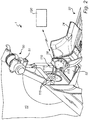
- a radiation therapy system 1 for which the present invention is applicable comprises a radiation unit 10 and a patient positioning unit 20.
- the radiation unit 10 there are provided radioactive sources, radioactive source holders, a collimator body, and external shielding elements.
- the collimator body comprises a large number of collimator channels directed towards a common focus, in a manner as is commonly known in the art.
- the collimator body also acts as a radiation shield preventing radiation from reaching the patient other than through the collimator channels.
- Examples of collimator arrangements in radiation therapy systems applicable to the present invention can be found in WO 2004/06269 A1 , which is hereby incorporated by reference.
- the patient positioning unit 20 comprises a rigid framework 22, a slidable or movable carriage 24, and motors (not shown) for moving the carriage 24 in relation to the framework 22.
- the carriage 24 is further provided with a patient bed (not shown) for carrying and moving the entire patient.
- a fixation arrangement 28 for receiving and fixing a stereotactic fixation unit (not show), either directly or via an adapter unit (not shown), and thereby preventing the stereotactic fixation unit from translational or rotational movement in relation to the movable carriage 24.
- the patient can be translated using the patient positioning unit 20 in the coordinate system of the radiation therapy system 1 or the patient positioning unit 20, along at least in the three orthogonal axes x, y, and z shown in Fig. 1 .
- the patient can, in some embodiments, also be translated along, for example, a rotational axis.
- An imaging system 50 for capturing images of a patient for example, in connection with treatment planning or treatment is arranged or located at the radiation unit 10, for example, a cone beam computed tomography (CBCT) system.
- CBCT cone beam computed tomography
- the imaging system 50 includes an X-ray source 51 and a detector 52.
- the X-ray source 51 and detector 52 are arranged to rotate around a rotation axis c (see Fig. 1 ) of a coordinate system (a, b, c) of the imaging system 50 to capture images of a patient located on the patient bed 26 at different angles.
- the X-ray source 51 and the detector 52 rotate around the z-axis of the patient positioning unit 20, which is aligned with the rotation axis c of the imaging system 50.
- a three-dimensional image is generated by rotating the imaging system around the object in very small steps (e.g. ⁇ 1°) around a single axis of rotation while taking a series of two-dimensional X-ray images.
- the object is rotated around the imaging in small steps.
- the imaging device or the object is rotated, for example, 180° or 360° around the object or imaging device, respectively.
- a final three-dimensional image can be numerically reconstructed based on the two- dimensional images and can be displayed either as a series of sectional images or a three-dimensional image.
- the described embodiment concerns a radiation therapy system for providing gamma radiation therapy to a target volume in the head of human patient.
- Such therapy is often referred to as stereotactic surgery.
- the patient head is fixed in a stereotactic fixation unit, for example, using a bite-block and a fixation unit in the form of a stereotactic head frame, which comprises engagement points adapted for engagement with the fixation arrangement 28 of the radiation therapy system.
- the head of the patient is fixed in the stereotactic frame, which in turn is fixedly attached to the patient positioning system via the fixation arrangement 28.
- the entire patient is moved.
- FIG. 2 an embodiment of the system according to the present invention will be discussed.
- the system 100 according to the present invention is schematically shown together with a schematically illustrated radiation unit 10 and an imaging system 50.
- the system 1 according to the present invention comprises on the general level a calibration tool 110 arranged to be releasably and firmly attached to the fixation arrangement 28 of the radiation therapy system and processing unit 120, for example, a personal computer (PC).
- a calibration tool 110 arranged to be releasably and firmly attached to the fixation arrangement 28 of the radiation therapy system and processing unit 120, for example, a personal computer (PC).
- PC personal computer
- FIG. 3 a more detailed view of an embodiment of the calibration tool 110 is shown.
- the calibration tool 110 is arranged to be easily aligned and positioned exactly in the stereotactic fixation unit coordinate system. By attaching the calibration tool 110 firmly by means of attachment means 118 without any possibility to movement of the calibration tool 110 relative to the patient positioning unit 20, it can be secured that the calibration tool is located at a defined and predetermined position, x cal.tool , y cal.tool , and z cal.tool , in the stereotactic fixation unit coordinate system and that it is kept still during image acquisition.
- the calibration tool 110 comprises at least one reference object or mark 112 having predetermined or known positions, respectively, in the stereotactic fixation unit coordinate system when the tool 110 is attached to the fixation arrangement 28. That is, positions of the reference objects or marks 112 relative to the predetermined position of the calibration tool 110 are known and thus have predetermined coordinates in the stereotactic fixation unit coordinate system.
- the reference objects 112 are made of a material and are arranged and shaped such that they can be identified in the two-dimensional images captured by the detector 52 of the imaging system 50.
- the calibration tool 110 comprises four reference objects 112 each including a rod 116 provided with a steel ball 115 attached on a plate 119.
- Each reference object 112 has a predetermined position in the stereotactic fixation unit coordinate system when the calibration tool 110 is attached to the fixation arrangement 28.
- the reference objects 112 are made of a material that attenuates the X-ray radiation emanating from the imagining unit or X-ray source 51 such as steel.
- the X-rays are attenuated by the reference objects 112 which entails that a representation of each reference object is captured by the detector and that a representation, as a shadow, can be seen in each image. The procedure for identifying each reference object representation will be described below.
- a processing unit 120 is connectable to the imaging system 50 such two-way communications is allowed, for example, wirelessly using, for example, Bluetooth or WLAN. Thereby, the processing unit 120 may, for example, obtain image information from the imaging system 50 and send instructions to imaging system 50 to initiate an image scanning procedure.
- the processing unit 120 is configured to calculate a transformation or a translational and rotational position difference between the position of the calibration tool 110 in the stereotactic coordinate system and a position of the calibration tool 110 in the imaging system coordinate system.
- the coordinate system of the stereotactic fixation unit (as defined by the axes x, y, and z) in which the calibration tool 110 is positioned is not aligned with the coordinate system of the imaging system (defined by the axes a, b, and c) due to, for example, manufacturing tolerances.
- the processing unit 120 determines the position, a cal.tool , b cal.tool , and c cal.tool , of the calibration tool 110 in the coordinate system of the imaging system 50 or rather the positions of the reference objects, i.e. a set of coordinates is obtained where each reference object is associated with three coordinates.
- the coordinates of each reference object 114 are determined resulting in an array of position coordinates.
- the processing unit 120 is configured to calculate a transformation between the determined position of the calibration tool in the coordinate system related to the imaging system, a cal.tool , b cal.tool , and c cal.tool , and a position of the calibration tool in the stereotactic fixation unit coordinate system, x cal.tool , y cal.tool , and z cal.tool , to determine a relationship between the coordinate system related to the imaging system and the position of the calibration tool in the stereotactic fixation unit coordinate system.
- the transformation between the known positions of the reference marks in the stereotactic fixation unit coordinate system and the determined positions of the calibration tool in the coordinate system related to the imaging system are determined.
- the calculation is based on the reference objects image coordinates d xy , positions r ob of the reference objects 112 in the stereotactic coordinate system relative to an origin, o, of the calibration tool 110 and a position r so of the origin, o, of the calibration tool 110 relative to the imaging unit 51.
- the calculation of the transformation is based positions r sd of the reference objects relative to the imaging unit 51, the positions r o'b of the reference objects in the imaging coordinate system and positions r so of the calibration tool relative to the imaging unit 51.
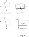
- the calculation of the transformation is further based on a distance SDD (see Fig. 4 ) between the imaging unit 51 and the detector 52 and a detector rotation between a position of the detector in the stereotactic coordinate system and a position of the detector in the imaging unit coordinate system.
- the vector rotation is defined in three parameters, where q and w are out-of-plane rotation angles and n is the in-plane rotation angle.
- the detector plane is aligned such that the v axis is parallel to the z axis and the u axis is parallel to the y axis.
- the rotation angle of the detector plane along the point of (u 0 , v 0 ) is n.
- the axis x, y, z relate to the stereotactic coordinate system (see Fig. 1 ) and u and v relate to the detector plane.
- vectors r sb between the reference objects positions and the position of the imaging unit 51 is determined based on the respective reference objects image coordinates d xy and an assumption that the vectors r sb between the reference objects positions and the position of the imaging unit 51 are parallel, for respective reference objects 112, with vectors r sd between positions the reference objects image coordinates d xy and the imaging unit 51 and using the relation between the vectors r sd between the reference objects positions and the position of the imaging unit 51 and the vectors r sb between positions the reference objects image coordinates d xy and the imaging unit 51 in calculating the transformation.
- positions r o'b' of the reference objects 112 relative to the origin o of the calibration tool 110 in the imaging system coordinate system is calculated based on the positions r ob of the reference objects relative to the origin o of the calibration tool 110 in the stereotactic coordinate system and the transformation is calculated based on the reference objects image coordinates d xy , the coordinates r o'b' of the reference objects in the imaging coordinate system and coordinates r so of the calibration tool relative to the imaging unit 51.
- Fig. 4 - 9 the method according to the present invention for calibrating an imaging system 50 for capturing images of a patient in connection with treatment planning or treatment in a radiation therapy system will be described.
- the method may, for example, be performed in a system as described in Fig. 2 .
- Figs. 4 - 6 schematically show geometries during the imaging procedure and
- Figs. 7 - 9 show flow charts of embodiments of the method according to the present invention.
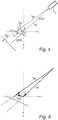
- the geometry is schematically illustrated seen from front of the radiation unit 10, in this embodiment a Gamma knife, i.e. in a counter-direction to the direction of the z-axis of the stereotactic coordinate system shown in Fig. 1 .
- the X-ray source 51 at position s (i.e. at coordinates a s , b s , c s of the imaging system coordinate system), emits radiation which is attenuated by a reference object 112, at position b (i.e. at coordinates x b , y b , z b in the stereotactic coordinate system).
- a clearly distinguishable shadow can then be detected on the detector 52 at position d (d x , d y ).
- the position of the representation of each reference object, d, in space i.e. x d , y d , z d in the stereotactic coordinate system.
- the calibration tool 110 is located at point o, i.e. a reference point of the calibration tool 110 is located at point x o , y o , z o in the stereotactic coordinate system.
- the position of the calibration tool 110 in the imaging system 50 is o', i.e. a o' , b o' , c o' .
- the vector r sb is the vector from point s to point b, i.e. the vector from the X-ray source 51 to respective reference object 112.
- the vector r ob is the vector from point o to point b, i.e. the vector from the center point of the calibration tool 110 to respective reference object 112. This vector r ob is known.
- the vector r so is the vector from point s to point o, i.e. the vector from the X-ray source 51 to the calibration tool 110.
- SDD is the "Source to Detector Distance", i.e. the distance between the X-ray source 51 to the detector 52.
- the gantry angle, ⁇ defines the angle between a current position, s, of the X-ray source 51 and the y-axis.
- the angle ⁇ defines the rotation for which correction is required, thus, the position, o', of the calibration tool 110 in the coordinate system of the imaging system 50 and compared to the position, o, of the calibration tool 110 in the stereotactic coordinate system.
- Fig. 5 is a more detailed view of the geometry shown in Fig. 4 .
- the notation r sb denotes the vector from point s (the X-ray source 51) to point b (the respective reference object 112). It is assumed that the position of the reference objects 112 relative to the center point, o, of the calibration tool 110 is known.
- the vector r sd (x d , y d , z d ) can be calculated from the images for example by center of mass calculation.
- Each representation of a reference object 112 will occupy a region on the detector surface (i.e. in the image) larger than a pixel.
- one point or pixel, in on the detector surface is selected for each reference object that accurately represents its projection.
- the vector r sd (x d , y d , z d ) can be determined.
- the reference objects 112 have a high contrast against the background and thresholding is therefore an efficient method for identifying or determining the projections.
- the calibration tool 110 and the reference objects 112 are preferably designed such that no overlaps, either horizontally or vertically, between different projections arise in the images.
- a region of interest is determined for each projection and the point that is determined to accurately represent the projection is selected from that region of interest, for example, using a center of mass calculation.
- r sb ⁇ ⁇ r sd
- ⁇ is a scalar.
- Equation (10) is solved for each reference object in each image.
- three reference objects are used and 300 images are captured during an imaging session.
- equation (10) may, according to preferred embodiments, be solved numerically, in a least-squares sense.
- R SAD is the distance from the source, i.e. the X-ray source 51, to the axis through origo of the calibration tool 110, i.e. the position of the calibration tool 110.
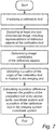
- Fig. 7 the general steps of an embodiment of the method according to the present invention for calibrating an imaging system 50 for capturing images of a patient in connection with treatment planning or treatment in a radiation therapy system will be described.
- the method may, for example, be performed in a system as described in Fig. 2 .
- a first step may be to perform a calibration of image quality parameters of the imaging system 50 including determining a rotational axis of the imaging system 50.
- the imaging system 50 may not need a calibration and calibration data can be stored in a calibration file.
- step 210 an image scanning procedure is initiated and the releasably attached calibration tool 110 is irradiated using the radiation unit 51 of the imaging system 50.
- At step 220 at least one two-dimensional image including cross-sectional representations of the reference objects 112 of the calibration tool 110 is captured using the detector 52 of the imaging system 50 during the image scanning procedure.
- the image coordinates d xy of the representation or projection of each reference object 112 is identified or determined in the captured images.
- a point for each object 112 is determined that represents its projection is determined. Due to the size of the objects 112, their projections will occupy regions in the images larger than a pixel and therefore it will be efficient to identify point that represents the central point. For example, thresholding can be used to separate the projections from the background.
- the reference objects 112 are arranged on the calibration tool 110 such that no projections overlap either horizontally or vertically. A summing in the non-overlapping direction and an identifying of contiguous nonzero regions are performed. This procedure is repeated in both directions for each of the segmented strips. The sought point can be found in the resulting region of interest. A center of mass calculation can for example be used for this purpose.
- a position of the origin o of the calibration tool 110 in relation to the imaging unit 51 or the vector r so between the imaging unit 51 and the origin o of the calibration tool is obtained.
- the vector r so between the imaging unit 51 and the origin o of the calibration tool is calculated and in other embodiments of the present invention, the vector r so between the imaging unit 51 and the origin o of the calibration tool is predetermined.
- a transformation including a translational and rotational position difference between the position of the calibration tool 110 in the stereotactic coordinate system and a position of the calibration tool 110 in an imaging system coordinate system is calculated using, for example, the equations (1) - (33) described above. Generally, the calculation is based on the reference objects image coordinates d xy , positions r ob of the reference objects 112 in the stereotactic coordinate system relative to an origin o of the calibration tool 110 and a position r so of the origin o of the calibration tool 110 relative to the imaging unit 51. If SAD is not predetermined, SAD is calculated at the same time as the transformation is calculated.
- the transformation that has been calculated can be used for calibrating the imaging system 50 in relation to the radiation therapy system 1.
- Fig. 8 steps of another embodiment of the method according to the present invention for calibrating an imaging system 50 for capturing images of a patient in connection with treatment planning or treatment in a radiation therapy system will be described.
- the method may, for example, be performed in a system as described in Fig. 2 .
- a first step may be to perform a calibration of image quality parameters of the imaging system 50 including determining a rotational axis of the imaging system 50.
- the imaging system 50 may not need a calibration and calibration data can be stored in a calibration file.
- step 310 an image scanning procedure is initiated and the releasably attached calibration tool 110 is irradiated using the radiation unit 51 of the imaging system 50.
- At step 320 at least one two-dimensional image including cross-sectional representations of the reference objects 112 of the calibration tool 110 is captured using the detector 52 of the imaging system 50 during the image scanning procedure.
- the image coordinates d xy of the representation or projection of each reference object 112 is identified or determined in the captured images.
- a point for each object 112 is determined that represents its projection is determined. Due to the size of the objects 112, their projections will occupy regions in the images larger than a pixel and therefore it will be efficient to identify point that represents the central point. For example, thresholding can be used to separate the projections from the background.
- the reference objects 112 are arranged on the calibration tool 110 such that no projections overlap either horizontally or vertically, see Fig. 4 .
- a summing in the non-overlapping direction and an identifying of contiguous nonzero regions are performed. This procedure is repeated in both directions as shown in Fig. 4 for each of the segmented strips.
- the sought point can be found in the resulting region of interest.
- a center of mass calculation can for example be used for this purpose.
- positions r sd of the reference objects 112 relative to the imaging unit 51 is determined or calculated based on the reference objects image coordinates d xy and a position r sd of the detector 52 relative to the imaging unit or X-ray source 51.
- a position of the origin o of the calibration tool 110 in relation to the imaging unit 51 is obtained or the vector r so between the imaging unit 51 and the origin o of the calibration tool.
- the vector r so between the imaging unit 51 and the origin o of the calibration tool is calculated and, in other embodiments of the present invention, the vector r so between the imaging unit 51 and the origin o of the calibration tool is predetermined.
- a transformation including a translational and rotational position difference between the position of the calibration tool 110 in the stereotactic coordinate system and a position of the calibration tool 110 in an imaging system coordinate system is calculated using, for example, the equations (1) - (31) described above. Generally, the calculation is based on the positions r sd of the reference objects relative to the imaging unit 51, positions r o'b of the reference objects in the imaging coordinate system and a position r so of the origin o of the calibration tool 110 relative to the imaging unit 51. If SAD is not predetermined, SAD is calculated at the same time as the transformation is calculated. In a following step, the transformation that has been calculated can be used for calibrating the imaging system 50 in relation to the radiation therapy system 1.
- a first step may be to perform a calibration of image quality parameters of the imaging system 50 including determining a rotational axis of the imaging system 50.
- the imaging system 50 may not need a calibration and calibration data can be stored in a calibration file.
- an image scanning procedure is initiated and the releasably attached calibration tool 110 is irradiated using the radiation unit 51 of the imaging system 50.
- the image coordinates d xy of the representation or projection of each reference object 112 is identified or determined in the captured images.
- a point for each object 112 is determined that represents its projection is determined. Due to the size of the objects 112, their projections will occupy regions in the images larger than a pixel and therefore it will be efficient to identify point that represents the central point. For example, thresholding can be used to separate the projections from the background.
- the reference objects 112 are arranged on the calibration tool 110 such that no projections overlap either horizontally or vertically, see Fig. 4 .
- a summing in the non-overlapping direction and an identifying of contiguous nonzero regions are performed. This procedure is repeated in both directions as shown in Fig. 4 for each of the segmented strips.
- the sought point can be found in the resulting region of interest.
- a center of mass calculation can for example be used for this purpose.
- vectors r sb between the reference objects positions and the position of the imaging unit 51 are determined based on the respective reference objects image coordinates d xy and an assumption that the vectors r sb between the reference objects positions and the position of the imaging unit 51 are parallel, for respective reference objects 112, with vectors r sd between positions the reference objects image coordinates d xy and the imaging unit 51.
- a position of the origin o of the calibration tool 110 in relation to the imaging unit 51 is obtained or the vector r so between the imaging unit 51 and the origin o of the calibration tool.
- the vector r so between the imaging unit 51 and the origin o of the calibration tool is calculated and, in other embodiments of the present invention, the vector r so between the imaging unit 51 and the origin o of the calibration tool is predetermined.
- a transformation including a translational and rotational position difference between the position of the calibration tool 110 in the stereotactic coordinate system and a position of the calibration tool 110 in an imaging system coordinate system is calculated using, for example, the equations (1) - (31) described above using also the relation between the vectors r sd between the reference objects positions and the position of the imaging unit 51 and the vectors r sb between positions the reference objects image coordinates d xy and the imaging unit 51 in calculating the transformation. If SAD is not predetermined, SAD is calculated at the same time as the transformation is calculated.
- the transformation that has been calculated can be used for calibrating the imaging system 50 in relation to the radiation therapy system 1.
- the embodiments aspects and examples which do not fall within the scope of the claims are provided for illustrative purpose only and do not form part of the present invention.
- the invention is defined in the claims as follows.
Landscapes
- Health & Medical Sciences (AREA)
- Life Sciences & Earth Sciences (AREA)
- Engineering & Computer Science (AREA)
- Biomedical Technology (AREA)
- Medical Informatics (AREA)
- Pathology (AREA)
- Nuclear Medicine, Radiotherapy & Molecular Imaging (AREA)
- Radiology & Medical Imaging (AREA)
- Animal Behavior & Ethology (AREA)
- General Health & Medical Sciences (AREA)
- Public Health (AREA)
- Veterinary Medicine (AREA)
- Heart & Thoracic Surgery (AREA)
- Physics & Mathematics (AREA)
- Biophysics (AREA)
- High Energy & Nuclear Physics (AREA)
- Optics & Photonics (AREA)
- Molecular Biology (AREA)
- Surgery (AREA)
- Theoretical Computer Science (AREA)
- Pulmonology (AREA)
- Dentistry (AREA)
- Oral & Maxillofacial Surgery (AREA)
- Radiation-Therapy Devices (AREA)
- Image Processing (AREA)
Claims (18)
- Verfahren zur Kalibrierung eines Bildgebungssystems (50), das Bilder eines Patienten in Bezug zu einem Strahlungstherapiesystem (1) erfasst, wobei das Strahlungstherapiesystem eine Strahlungstherapieeinheit (10) mit fixiertem Strahlungsfokus, und ein Positionierungssystem (20) zum Positionieren eines Patienten in Bezug zu dem fixierten Fokus in der Strahlungstherapieeinheit (10) umfasst, wobei das Verfahren die Schritte umfasst:Bestrahlen eines Kalibrierungswerkzeugs (110), das mindestens ein Referenzobjekt umfasst, mit ionisierender Strahlung während eines Bildscanvorgangs unter Verwendung einer Strahlungseinheit (51) des Bildgebungssystems (50), wobei das Kalibrierungswerkzeug (110) und das mindestens eine Referenzobjekt (112) bekannte Positionen in dem stereotaktischen Koordinatensystem aufweisen;Erfassen mindestens eines zweidimensionalen Bildes, das Querschnittdarstellungen von Referenzobjekten (112) des Kalibrierungswerkzeugs (110) einschließt, unter Verwendung eines Detektors (52) des Bildgebungssystems (50) während des Bildscanvorgangs;Bestimmen von Bildkoordinaten (dxy) der Darstellung jedes Referenzobjekts (112) in den erfassten Bildern;Erhalten einer Position (rso) des Ursprungs (o) des Kalibrierungswerkzeugs (110) relativ zu der Bildgebungseinheit (51) in dem stereotaktischen Koordinatensystem; undBerechnen einer Transformation zwischen der SD-Position des Kalibrierungswerkzeugs (110) in dem stereotaktischen Koordinatensystem und einer 3D-Position des Kalibrierungswerkzeugs (110) in einem Koordinatensystem des Bildgebungssystems,wobei die Berechnung auf den Bildkoordinaten der Referenzobjekte (dxy), Positionen (rob) der Referenzobjekte (112) in dem stereotaktischen Koordinatensystem relativ zu einem Ursprung (o) des Kalibrierungswerkzeugs (110) und der Position (rso) des Ursprungs (o) des Kalibrierungswerkzeugs (110) relativ zu der Bildgebungseinheit (51) basiert.
- Verfahren nach Anspruch 1, wobei Erhalten einer Position (rso) des Ursprungs (o) des Kalibrierungswerkzeugs (110) relativ zu der Bildgebungseinheit (51) Berechnen der Position (rso) des Ursprungs (o) des Kalibrierungswerkzeugs (110) relativ zu der Bildgebungseinheit (51) einschließt.
- Verfahren nach Anspruch 1 oder 2, des Weiteren umfassend:Bestimmen von Positionen (rsd) der Referenzobjekte (112) relativ zu der Bildgebungseinheit (51) basierend auf den Bildkoordinaten der Referenzobjekte (dxy) und einer Position (rsd) des Detektors (52) relativ zu der Bildgebungseinheit (51); undBerechnen der Transformation basierend auf Positionen (rsd) der Referenzobjekte relativ zu der Bildgebungseinheit (51), den Positionen (ro'b) der Referenzobjekte in dem Bildgebungskoordinatensystem und Positionen (rso) des Kalibrierungswerkzeugs relativ zu der Bildgebungseinheit (51).
- Verfahren nach einem der Ansprüche 1 bis 3, wobei die Berechnung der Transformation des Weiteren auf einem Abstand (SDD) zwischen der Bildgebungseinheit (51) und dem Detektor (52) und einer Detektorrotation zwischen einer Position des Detektors in dem stereotaktischen Koordinatensystem und einer Position des Detektors in dem Koordinationssystem der Bildgebungseinheit basiert.
- Verfahren nach einem der Ansprüche 1 bis 4, das des Weiteren umfasst:Bestimmen von Vektoren (rsb) zwischen den Positionen der Referenzobjekte und der Position der Bildgebungseinheit (51) basierend auf den jeweiligen Bildkoordinaten der Referenzobjekte (dxy) und einer Annahme, dass die Vektoren (rsb) zwischen den Positionen der Referenzobjekte und der Position der Bildgebungseinheit (51) für jeweilige Referenzobjekte (112) parallel zu Vektoren (rsd) zwischen Positionen der Bildkoordinaten der Referenzobjekte (dxy) und der Bildgebungseinheit (51) sind; undVerwenden der Beziehung zwischen den Vektoren (rsd) zwischen den Positionen der Referenzobjekte und der Position der Bildgebungseinheit (51) und den Vektoren (rsb) zwischen Positionen der Bildkoordinaten der Referenzobjekte (dxy) und der Bildgebungseinheit (51) zum Berechnen der Transformation.
- Verfahren nach Anspruch 5, des Weiteren umfassend:Definieren der Beziehung zwischen den Vektoren (rsd) für die Bildkoordinaten der Referenzobjekte (dxy) relativ zu der Bildgebungseinheit (51) und den Vektoren (rsb) der Positionen der Referenzobjekte relativ zu der Bildgebungseinheit (51) als Skalar; undBestimmen eines Wertes des Skalars basierend auf den Positionen (rsd) der Referenzobjekte relativ zu der Bildgebungseinheit (51), den Positionen (ro'b) der Referenzobjekte in dem Bildgebungskoordinatensystem und Positionen (rso) des Kalibrierungswerkzeugs relativ zu der Bildgebungseinheit (51).
- Verfahren nach Anspruch 1 bis 6, des Weiteren umfassend:Berechnen von Positionen (ro'b') der Referenzobjekte (112) relativ zu dem Ursprung (o) des Kalibrierungswerkzeugs (110) in dem Koordinatensystem des Bildgebungssystems basierend auf den Positionen (rob) der Referenzobjekte relativ zu dem Ursprung (o) des Kalibrierungswerkzeugs (110) in dem stereotaktischen Koordinatensystem; undBerechnen der Transformation basierend auf den Bildkoordinaten der Referenzobjekte (dxy), den Koordinaten (ro'b') der Referenzobjekte in dem Bildgebungskoordinatensystem und Koordinaten (rso) des Kalibrierungswerkzeugs relativ zu der Bildgebungseinheit (51).
- Verfahren nach einem der Ansprüche 1 bis 7, wobei jede Beziehung zwischen einer Position eines Referenzobjekts in dem stereotaktischen Koordinatensystem und einer Position jenes Referenzobjekts in dem Bildgebungskoordinatensystem als Vektor, der eine Translations- und Rotationstransformation definiert, unter Verwendung eines Vektorrotationsverfahrens berechnet wird.
- Verfahren nach einem der Ansprüche 1 bis 8, wobei das Positionierungssystem eine Fixieranordnung (28) zum lösbaren und festen Koppeln einer stereotaktischen Fixiereinheit einschließt, um mindestens einen Teil des Patienten in Bezug auf das Positionierungssystem (20) zu immobilisieren.
- System zur Kalibrierung eines Bildgebungssystems (50), das Bilder eines Patienten in Bezug auf ein Strahlungstherapiesystem (1) erfasst, wobei das Strahlungstherapiesystem eine Strahlungstherapieeinheit (10) mit fixiertem Strahlungsfokus und ein Positionierungssystem (20) zum Positionieren eines Patienten in Bezug auf den fixierten Fokus in der Strahlungstherapieeinheit (10) umfasst, wobei:das Bildgebungssystem (50) konfiguriert ist, um ein Kalibrierungswerkzeug (110), das mindestens ein Referenzobjekt umfasst, während eines Bildscanvorgangs unter Verwendung einer Strahlungseinheit (51) mit ionisierender Strahlung zu bestrahlen, wobei das Kalibrierungswerkzeug (110) und das mindestens eine Referenzobjekt (112) bekannte Positionen in dem stereotaktischen Koordinatensystem aufweisen;das Bildgebungssystem (50) konfiguriert ist, um mindestens ein zweidimensionalen Bild, das Querschnittdarstellungen von Referenzobjekten (112) des Kalibrierungswerkzeugs (110) einschließt, unter Verwendung eines Detektors (52) während des Bildscanvorgangs zu erfassen;eine Verarbeitungseinheit (120), die konfiguriert ist zum:Bestimmen von Bildkoordinaten (dxy) der Darstellung jedes Referenzobjekts (112) in den erfassten Bildern;Erhalten einer Position (rso) des Ursprungs (o) des Kalibrierungswerkzeugs (110) relativ zu der Bildgebungseinheit (51) in dem stereotaktischen Koordinatensystem; undBerechnen einer Transformation zwischen der 3D-Position des Kalibrierungswerkzeugs (110) in dem stereotaktischen Koordinatensystem und einer 3D-Position des Kalibrierungswerkzeugs (110) in einem Koordinatensystem eines Bildgebungssystems, wobei die Berechnung auf den Bildkoordinaten der Referenzobjekte (dxy), Positionen (rob) der Referenzobjekte (112) in dem stereotaktischen Koordinatensystem relativ zu einem Ursprung (o) des Kalibrierungswerkzeugs (110) und einer Position (rso) des Ursprungs (o) des Kalibrierungswerkzeugs (110) relativ zu der Bildgebungseinheit (51) basiert.
- System nach Anspruch 10, wobei die Verarbeitungseinheit (120) des Weiteren konfiguriert ist, um die Position (rso) des Ursprungs (o) des Kalibrierungswerkzeugs (110) relativ zu der Bildgebungseinheit (51) zu berechnen.
- System nach Anspruch 10 oder 11, wobei die Verarbeitungseinheit (120) des Weiteren konfiguriert ist zum:Bestimmen von Positionen (rsd) der Referenzobjekte (112) relativ zu der Bildgebungseinheit (51) basierend auf den Bildkoordinaten der Referenzobjekte (dxy) und einer Position (rsd) des Detektors (52) relativ zu der Bildgebungseinheit (51); undBerechnen der Transformation basierend auf Positionen (rsd) der Referenzobjekte relativ zu der Bildgebungseinheit (51), den Positionen (ro'b) der Referenzobjekte in dem Bildgebungskoordinatensystem und Positionen (rso) des Kalibrierungswerkzeugs relativ zu der Bildgebungseinheit (51).
- System nach einem der Ansprüche 10 bis 12, wobei die Verarbeitungseinheit (120) des Weiteren konfiguriert ist, um die Transformation basierend auf einem Abstand (SDD) zwischen der Bildgebungseinheit (51) und dem Detektor (52) und einer Detektorrotation zwischen einer Position des Detektors in dem stereotaktischen Koordinatensystem und einer Position des Detektors in dem Koordinationssystem der Bildgebungseinheit zu berechnen.
- System nach einem der Ansprüche 10 bis 13, wobei die Verarbeitungseinheit (120) des Weiteren konfiguriert ist zum:Bestimmen von Vektoren (rsb) zwischen den Positionen der Referenzobjekte und der Position der Bildgebungseinheit (51) basierend auf den jeweiligen Bildkoordinaten der Referenzobjekte (dxy) und einer Annahme, dass die Vektoren (rsb) zwischen den Positionen der Referenzobjekte und der Position der Bildgebungseinheit (51) für jeweilige Referenzobjekte (112) parallel zu Vektoren (rsd) zwischen Positionen der Bildkoordinaten der Referenzobjekte (dxy) und der Bildgebungseinheit (51) sind; undVerwenden der Beziehung zwischen den Vektoren (rsd) zwischen den Positionen der Referenzobjekte und der Position der Bildgebungseinheit (51) und den Vektoren (rsb) zwischen Positionen der Bildkoordinaten der Referenzobjekte (dxy) und der Bildgebungseinheit (51) zum Berechnen der Transformation.
- System nach Anspruch 14, wobei die Verarbeitungseinheit (120) des Weiteren konfiguriert ist zum:Definieren der Beziehung zwischen den Vektoren (rsd) für die Bildkoordinaten der Referenzobjekte (dxy) relativ zu der Bildgebungseinheit (51) und den Vektoren (rsb) der Positionen der Referenzobjekte relativ zu der Bildgebungseinheit (51) als Skalar; undBestimmen eines Wertes des Skalars basierend auf den Positionen (rsd) der Referenzobjekte relativ zu der Bildgebungseinheit (51), den Positionen (ro'b) der Referenzobjekte in dem Bildgebungskoordinatensystem und Positionen (rso) des Kalibrierungswerkzeugs relativ zu der Bildgebungseinheit (51).
- System nach einem der Ansprüche 10 bis 15, wobei die Verarbeitungseinheit (120) des Weiteren konfiguriert ist zum:Berechnen von Positionen (ro'b') der Referenzobjekte (112) relativ zu dem Ursprung (o) des Kalibrierungswerkzeugs (110) in dem Koordinatensystem des Bildgebungssystems basierend auf den Positionen (rob) der Referenzobjekte relativ zu dem Ursprung (o) des Kalibrierungswerkzeugs (110) in dem stereotaktischen Koordinatensystem; undBerechnen der Transformation basierend auf Bildkoordinaten (dxy) der Referenzobjekte, den Koordinaten (ro'b') der Referenzobjekte in dem Bildgebungskoordinatensystem und Koordinaten (rso) des Kalibrierungswerkzeugs relativ zu der Bildgebungseinheit (51).
- System nach einem der Ansprüche 10 bis 16, wobei jede Beziehung zwischen einer Position eines Referenzobjekts in dem stereotaktischen Koordinatensystem und einer Position jenes Referenzobjekts in dem Bildgebungskoordinatensystem als Vektor, der eine Translations- und Rotationstransformation definiert, unter Verwendung eines Vektorrotationsverfahrens berechnet wird.
- System nach einem der Ansprüche 10 bis 17, wobei das Positionierungssystem eine Fixieranordnung (28) zum lösbaren und festen Koppeln einer stereotaktischen Fixiereinheit einschließt, um mindestens einen Teil des Patienten in Bezug auf das Positionierungssystem (20) zu immobilisieren.
Applications Claiming Priority (1)
| Application Number | Priority Date | Filing Date | Title |
|---|---|---|---|
| PCT/EP2014/057659 WO2015158372A1 (en) | 2014-04-15 | 2014-04-15 | Method and system for calibration |
Publications (2)
| Publication Number | Publication Date |
|---|---|
| EP3131629A1 EP3131629A1 (de) | 2017-02-22 |
| EP3131629B1 true EP3131629B1 (de) | 2020-01-08 |
Family
ID=50513245
Family Applications (1)
| Application Number | Title | Priority Date | Filing Date |
|---|---|---|---|
| EP14718059.0A Active EP3131629B1 (de) | 2014-04-15 | 2014-04-15 | Verfahren und system zur kalibrierung |
Country Status (5)
| Country | Link |
|---|---|
| US (1) | US11179134B2 (de) |
| EP (1) | EP3131629B1 (de) |
| JP (1) | JP2017511213A (de) |
| CN (1) | CN106255531B (de) |
| WO (1) | WO2015158372A1 (de) |
Families Citing this family (16)
| Publication number | Priority date | Publication date | Assignee | Title |
|---|---|---|---|---|
| GB2530790B (en) * | 2014-10-02 | 2016-10-19 | Vision Rt Ltd | Method of calibrating a patient monitoring system for use with a radiotherapy treatment apparatus |
| US10223792B2 (en) * | 2017-02-02 | 2019-03-05 | Elekta Ab (Publ) | System and method for detecting brain metastases |
| CN107707815B (zh) * | 2017-09-26 | 2019-10-15 | 北京金山安全软件有限公司 | 一种图像处理方法、装置、电子设备及存储介质 |
| GB2568544B (en) * | 2017-11-21 | 2019-11-13 | Elekta ltd | Methods and systems for checking alignment of components of a radiotherapy system |
| CN108937987B (zh) * | 2018-05-22 | 2021-07-02 | 上海联影医疗科技股份有限公司 | 一种确定模体中标记物位置的方法和系统 |
| CN109908497B (zh) * | 2019-04-01 | 2021-11-30 | 上海联影医疗科技股份有限公司 | 坐标校准装置、系统、方法及介质 |
| CN112085797B (zh) * | 2019-06-12 | 2024-07-19 | 通用电气精准医疗有限责任公司 | 3d相机-医疗成像设备坐标系校准系统和方法及其应用 |
| CN110752029B (zh) * | 2019-10-21 | 2020-08-28 | 北京推想科技有限公司 | 一种病灶的定位方法及装置 |
| CN111514476B (zh) * | 2020-04-30 | 2022-03-15 | 江苏瑞尔医疗科技有限公司 | 一种用于x射线图像引导系统中的校准方法 |
| US11311747B2 (en) | 2020-07-16 | 2022-04-26 | Uih America, Inc. | Systems and methods for isocenter calibration |
| CN116600854B (zh) * | 2020-12-31 | 2024-11-22 | 西安大医集团股份有限公司 | 焦点验证方法、计划验证方法、系统、装置及存储介质 |
| CN117651916A (zh) * | 2021-09-22 | 2024-03-05 | Abb瑞士股份有限公司 | 用于校准机器人的方法和电子设备 |
| CN114533097A (zh) * | 2022-02-25 | 2022-05-27 | 上海极睿医疗科技有限公司 | C臂机x光源的定位方法、装置、系统和计算机可读介质 |
| EP4694772A1 (de) * | 2023-04-13 | 2026-02-18 | Medtronic Navigation, Inc. | Chirurgische positionierungsverfahren und verfahren zur bestimmung von regionen, die strahlung ausgesetzt sind |
| GB202312193D0 (en) * | 2023-08-09 | 2023-09-20 | Neurochase Tech Ltd | X-ray systems and methods |
| CN116850484B (zh) * | 2023-08-17 | 2024-03-26 | 迈胜医疗设备有限公司 | 图像引导系统及校准装置、位置校准方法、放射治疗设备 |
Family Cites Families (10)
| Publication number | Priority date | Publication date | Assignee | Title |
|---|---|---|---|---|
| SE522710C2 (sv) | 2002-07-05 | 2004-03-02 | Elekta Ab | Strålterapiapparat med flera uppsättningar hål i kollimatorringen där förskjutbara plattor bestämmer vilka håluppsättningar som strålkällorna ska använda, samt metod att variera strålfältet |
| EP1654516B1 (de) * | 2003-08-08 | 2012-11-28 | University Health Network | Verfahren und system zum kalibrieren einer quelle und detektorinstrument |
| JP2006051216A (ja) | 2004-08-12 | 2006-02-23 | Mitsubishi Heavy Ind Ltd | 放射線治療装置、放射線治療装置用治療台、及び放射線治療装置の座標校正方法 |
| WO2008098591A1 (en) * | 2007-02-15 | 2008-08-21 | Elekta Ab (Publ) | Method of calibrating a radiation therapy system |
| JP4941974B2 (ja) | 2007-03-20 | 2012-05-30 | 株式会社日立製作所 | 放射線治療用ベッド位置決めシステム、治療計画装置及びベッド位置決め装置 |
| EP2119397B1 (de) * | 2008-05-15 | 2013-12-18 | Brainlab AG | Bestimmung einer Kalibrier-Information für ein Röntgengerät |
| US8335363B2 (en) * | 2009-06-16 | 2012-12-18 | Jefferson Science Associates, Llc | Method for image reconstruction of moving radionuclide source distribution |
| WO2012146301A1 (en) | 2011-04-29 | 2012-11-01 | Elekta Ab (Publ) | Method for calibration and qa |
| US20130229495A1 (en) * | 2012-03-01 | 2013-09-05 | Ali-Reza Bani-Hashemi | Method for calibrating an imaging system |
| JP6004464B2 (ja) | 2012-03-19 | 2016-10-05 | 国立大学法人北海道大学 | 放射線治療制御装置および放射線治療制御プログラム |
-
2014
- 2014-04-15 US US15/302,414 patent/US11179134B2/en active Active
- 2014-04-15 JP JP2016562872A patent/JP2017511213A/ja active Pending
- 2014-04-15 CN CN201480077987.5A patent/CN106255531B/zh active Active
- 2014-04-15 EP EP14718059.0A patent/EP3131629B1/de active Active
- 2014-04-15 WO PCT/EP2014/057659 patent/WO2015158372A1/en not_active Ceased
Non-Patent Citations (1)
| Title |
|---|
| None * |
Also Published As
| Publication number | Publication date |
|---|---|
| CN106255531B (zh) | 2019-07-26 |
| US20170027540A1 (en) | 2017-02-02 |
| EP3131629A1 (de) | 2017-02-22 |
| US11179134B2 (en) | 2021-11-23 |
| WO2015158372A1 (en) | 2015-10-22 |
| JP2017511213A (ja) | 2017-04-20 |
| CN106255531A (zh) | 2016-12-21 |
Similar Documents
| Publication | Publication Date | Title |
|---|---|---|
| EP3131629B1 (de) | Verfahren und system zur kalibrierung | |
| EP2701802B1 (de) | Verfahren für kalibrierung und qa | |
| JP6886565B2 (ja) | 表面の動きを追跡する方法及び装置 | |
| US8417318B2 (en) | Calibrating tracking systems to remove position-dependent bias | |
| CN1672651B (zh) | 在有呼吸运动的情况下用于放射治疗的患者定位系统和方法 | |
| Gevaert et al. | Setup accuracy of the Novalis ExacTrac 6DOF system for frameless radiosurgery | |
| Yan et al. | A phantom study on the positioning accuracy of the Novalis Body system | |
| EP2285279B1 (de) | Automatisches patientenpositionierungssystem | |
| US20070025524A1 (en) | Method to implement full six-degree target shift corrections in radiotherapy | |
| US20070127622A1 (en) | Unified quality assurance for a radiation treatment delivery system | |
| JP6565080B2 (ja) | 放射線治療装置、その作動方法及びプログラム | |
| Pelizzari et al. | Interactive 3D patient—image registration | |
| CN108785872B (zh) | 4π多模态影像引导精确放射治疗系统 | |
| CN103028195A (zh) | 用于辐射治疗计划的组合成像模式 | |
| KR102619994B1 (ko) | 의용 화상 처리 장치, 기억 매체, 의용 장치, 및 치료 시스템 | |
| KR20220035428A (ko) | 의용 화상 처리 장치, 기억 매체, 의용 장치, 및 치료 시스템 | |
| US7635847B2 (en) | Non-invasive scanning device | |
| JP2022009850A (ja) | 校正の方法及びシステム | |
| JP3225139U (ja) | 校正のシステム | |
| Sharma et al. | Evaluation of automated image registration algorithm for image-guided radiotherapy (IGRT) | |
| Matinfar et al. | Small animal radiation research platform: imaging, mechanics, control and calibration | |
| KR20150065611A (ko) | Cbct/mr 하이브리드 시뮬레이션 시스템 및 방사선 치료를 위한 기준영상 생성 방법 | |
| Talbot et al. | A method for patient set-up guidance in radiotherapy using augmented reality | |
| Hoisak et al. | A history of surface guidance methods in radiation therapy | |
| Hadley | Video-based patient positioning for external beam radiation therapy. |
Legal Events
| Date | Code | Title | Description |
|---|---|---|---|
| STAA | Information on the status of an ep patent application or granted ep patent |
Free format text: STATUS: THE INTERNATIONAL PUBLICATION HAS BEEN MADE |
|
| PUAI | Public reference made under article 153(3) epc to a published international application that has entered the european phase |
Free format text: ORIGINAL CODE: 0009012 |
|
| STAA | Information on the status of an ep patent application or granted ep patent |
Free format text: STATUS: REQUEST FOR EXAMINATION WAS MADE |
|
| 17P | Request for examination filed |
Effective date: 20161012 |
|
| AK | Designated contracting states |
Kind code of ref document: A1 Designated state(s): AL AT BE BG CH CY CZ DE DK EE ES FI FR GB GR HR HU IE IS IT LI LT LU LV MC MK MT NL NO PL PT RO RS SE SI SK SM TR |
|
| AX | Request for extension of the european patent |
Extension state: BA ME |
|
| RIN1 | Information on inventor provided before grant (corrected) |
Inventor name: SJOELUND, JENS |
|
| DAX | Request for extension of the european patent (deleted) | ||
| GRAP | Despatch of communication of intention to grant a patent |
Free format text: ORIGINAL CODE: EPIDOSNIGR1 |
|
| STAA | Information on the status of an ep patent application or granted ep patent |
Free format text: STATUS: GRANT OF PATENT IS INTENDED |
|
| INTG | Intention to grant announced |
Effective date: 20190923 |
|
| GRAS | Grant fee paid |
Free format text: ORIGINAL CODE: EPIDOSNIGR3 |
|
| GRAA | (expected) grant |
Free format text: ORIGINAL CODE: 0009210 |
|
| STAA | Information on the status of an ep patent application or granted ep patent |
Free format text: STATUS: THE PATENT HAS BEEN GRANTED |
|
| AK | Designated contracting states |
Kind code of ref document: B1 Designated state(s): AL AT BE BG CH CY CZ DE DK EE ES FI FR GB GR HR HU IE IS IT LI LT LU LV MC MK MT NL NO PL PT RO RS SE SI SK SM TR |
|
| REG | Reference to a national code |
Ref country code: GB Ref legal event code: FG4D |
|
| REG | Reference to a national code |
Ref country code: CH Ref legal event code: EP |
|
| REG | Reference to a national code |
Ref country code: DE Ref legal event code: R096 Ref document number: 602014059645 Country of ref document: DE |
|
| REG | Reference to a national code |
Ref country code: IE Ref legal event code: FG4D |
|
| REG | Reference to a national code |
Ref country code: AT Ref legal event code: REF Ref document number: 1221950 Country of ref document: AT Kind code of ref document: T Effective date: 20200215 |
|
| REG | Reference to a national code |
Ref country code: NL Ref legal event code: MP Effective date: 20200108 |
|
| REG | Reference to a national code |
Ref country code: LT Ref legal event code: MG4D |
|
| PG25 | Lapsed in a contracting state [announced via postgrant information from national office to epo] |
Ref country code: FI Free format text: LAPSE BECAUSE OF FAILURE TO SUBMIT A TRANSLATION OF THE DESCRIPTION OR TO PAY THE FEE WITHIN THE PRESCRIBED TIME-LIMIT Effective date: 20200108 Ref country code: NO Free format text: LAPSE BECAUSE OF FAILURE TO SUBMIT A TRANSLATION OF THE DESCRIPTION OR TO PAY THE FEE WITHIN THE PRESCRIBED TIME-LIMIT Effective date: 20200408 Ref country code: LT Free format text: LAPSE BECAUSE OF FAILURE TO SUBMIT A TRANSLATION OF THE DESCRIPTION OR TO PAY THE FEE WITHIN THE PRESCRIBED TIME-LIMIT Effective date: 20200108 Ref country code: RS Free format text: LAPSE BECAUSE OF FAILURE TO SUBMIT A TRANSLATION OF THE DESCRIPTION OR TO PAY THE FEE WITHIN THE PRESCRIBED TIME-LIMIT Effective date: 20200108 Ref country code: PT Free format text: LAPSE BECAUSE OF FAILURE TO SUBMIT A TRANSLATION OF THE DESCRIPTION OR TO PAY THE FEE WITHIN THE PRESCRIBED TIME-LIMIT Effective date: 20200531 Ref country code: NL Free format text: LAPSE BECAUSE OF FAILURE TO SUBMIT A TRANSLATION OF THE DESCRIPTION OR TO PAY THE FEE WITHIN THE PRESCRIBED TIME-LIMIT Effective date: 20200108 |
|
| PG25 | Lapsed in a contracting state [announced via postgrant information from national office to epo] |
Ref country code: BG Free format text: LAPSE BECAUSE OF FAILURE TO SUBMIT A TRANSLATION OF THE DESCRIPTION OR TO PAY THE FEE WITHIN THE PRESCRIBED TIME-LIMIT Effective date: 20200408 Ref country code: SE Free format text: LAPSE BECAUSE OF FAILURE TO SUBMIT A TRANSLATION OF THE DESCRIPTION OR TO PAY THE FEE WITHIN THE PRESCRIBED TIME-LIMIT Effective date: 20200108 Ref country code: IS Free format text: LAPSE BECAUSE OF FAILURE TO SUBMIT A TRANSLATION OF THE DESCRIPTION OR TO PAY THE FEE WITHIN THE PRESCRIBED TIME-LIMIT Effective date: 20200508 Ref country code: LV Free format text: LAPSE BECAUSE OF FAILURE TO SUBMIT A TRANSLATION OF THE DESCRIPTION OR TO PAY THE FEE WITHIN THE PRESCRIBED TIME-LIMIT Effective date: 20200108 Ref country code: HR Free format text: LAPSE BECAUSE OF FAILURE TO SUBMIT A TRANSLATION OF THE DESCRIPTION OR TO PAY THE FEE WITHIN THE PRESCRIBED TIME-LIMIT Effective date: 20200108 Ref country code: GR Free format text: LAPSE BECAUSE OF FAILURE TO SUBMIT A TRANSLATION OF THE DESCRIPTION OR TO PAY THE FEE WITHIN THE PRESCRIBED TIME-LIMIT Effective date: 20200409 |
|
| REG | Reference to a national code |
Ref country code: DE Ref legal event code: R097 Ref document number: 602014059645 Country of ref document: DE |
|
| PG25 | Lapsed in a contracting state [announced via postgrant information from national office to epo] |
Ref country code: SK Free format text: LAPSE BECAUSE OF FAILURE TO SUBMIT A TRANSLATION OF THE DESCRIPTION OR TO PAY THE FEE WITHIN THE PRESCRIBED TIME-LIMIT Effective date: 20200108 Ref country code: DK Free format text: LAPSE BECAUSE OF FAILURE TO SUBMIT A TRANSLATION OF THE DESCRIPTION OR TO PAY THE FEE WITHIN THE PRESCRIBED TIME-LIMIT Effective date: 20200108 Ref country code: EE Free format text: LAPSE BECAUSE OF FAILURE TO SUBMIT A TRANSLATION OF THE DESCRIPTION OR TO PAY THE FEE WITHIN THE PRESCRIBED TIME-LIMIT Effective date: 20200108 Ref country code: SM Free format text: LAPSE BECAUSE OF FAILURE TO SUBMIT A TRANSLATION OF THE DESCRIPTION OR TO PAY THE FEE WITHIN THE PRESCRIBED TIME-LIMIT Effective date: 20200108 Ref country code: RO Free format text: LAPSE BECAUSE OF FAILURE TO SUBMIT A TRANSLATION OF THE DESCRIPTION OR TO PAY THE FEE WITHIN THE PRESCRIBED TIME-LIMIT Effective date: 20200108 Ref country code: CZ Free format text: LAPSE BECAUSE OF FAILURE TO SUBMIT A TRANSLATION OF THE DESCRIPTION OR TO PAY THE FEE WITHIN THE PRESCRIBED TIME-LIMIT Effective date: 20200108 Ref country code: ES Free format text: LAPSE BECAUSE OF FAILURE TO SUBMIT A TRANSLATION OF THE DESCRIPTION OR TO PAY THE FEE WITHIN THE PRESCRIBED TIME-LIMIT Effective date: 20200108 |
|
| PLBE | No opposition filed within time limit |
Free format text: ORIGINAL CODE: 0009261 |
|
| STAA | Information on the status of an ep patent application or granted ep patent |
Free format text: STATUS: NO OPPOSITION FILED WITHIN TIME LIMIT |
|
| REG | Reference to a national code |
Ref country code: AT Ref legal event code: MK05 Ref document number: 1221950 Country of ref document: AT Kind code of ref document: T Effective date: 20200108 |
|
| PG25 | Lapsed in a contracting state [announced via postgrant information from national office to epo] |
Ref country code: MC Free format text: LAPSE BECAUSE OF FAILURE TO SUBMIT A TRANSLATION OF THE DESCRIPTION OR TO PAY THE FEE WITHIN THE PRESCRIBED TIME-LIMIT Effective date: 20200108 |
|
| REG | Reference to a national code |
Ref country code: CH Ref legal event code: PL |
|
| 26N | No opposition filed |
Effective date: 20201009 |
|
| PG25 | Lapsed in a contracting state [announced via postgrant information from national office to epo] |
Ref country code: LI Free format text: LAPSE BECAUSE OF NON-PAYMENT OF DUE FEES Effective date: 20200430 Ref country code: IT Free format text: LAPSE BECAUSE OF FAILURE TO SUBMIT A TRANSLATION OF THE DESCRIPTION OR TO PAY THE FEE WITHIN THE PRESCRIBED TIME-LIMIT Effective date: 20200108 Ref country code: AT Free format text: LAPSE BECAUSE OF FAILURE TO SUBMIT A TRANSLATION OF THE DESCRIPTION OR TO PAY THE FEE WITHIN THE PRESCRIBED TIME-LIMIT Effective date: 20200108 Ref country code: CH Free format text: LAPSE BECAUSE OF NON-PAYMENT OF DUE FEES Effective date: 20200430 Ref country code: LU Free format text: LAPSE BECAUSE OF NON-PAYMENT OF DUE FEES Effective date: 20200415 |
|
| REG | Reference to a national code |
Ref country code: BE Ref legal event code: MM Effective date: 20200430 |
|
| PG25 | Lapsed in a contracting state [announced via postgrant information from national office to epo] |
Ref country code: PL Free format text: LAPSE BECAUSE OF FAILURE TO SUBMIT A TRANSLATION OF THE DESCRIPTION OR TO PAY THE FEE WITHIN THE PRESCRIBED TIME-LIMIT Effective date: 20200108 Ref country code: SI Free format text: LAPSE BECAUSE OF FAILURE TO SUBMIT A TRANSLATION OF THE DESCRIPTION OR TO PAY THE FEE WITHIN THE PRESCRIBED TIME-LIMIT Effective date: 20200108 Ref country code: BE Free format text: LAPSE BECAUSE OF NON-PAYMENT OF DUE FEES Effective date: 20200430 |
|
| PG25 | Lapsed in a contracting state [announced via postgrant information from national office to epo] |
Ref country code: IE Free format text: LAPSE BECAUSE OF NON-PAYMENT OF DUE FEES Effective date: 20200415 |
|
| PG25 | Lapsed in a contracting state [announced via postgrant information from national office to epo] |
Ref country code: TR Free format text: LAPSE BECAUSE OF FAILURE TO SUBMIT A TRANSLATION OF THE DESCRIPTION OR TO PAY THE FEE WITHIN THE PRESCRIBED TIME-LIMIT Effective date: 20200108 Ref country code: MT Free format text: LAPSE BECAUSE OF FAILURE TO SUBMIT A TRANSLATION OF THE DESCRIPTION OR TO PAY THE FEE WITHIN THE PRESCRIBED TIME-LIMIT Effective date: 20200108 Ref country code: CY Free format text: LAPSE BECAUSE OF FAILURE TO SUBMIT A TRANSLATION OF THE DESCRIPTION OR TO PAY THE FEE WITHIN THE PRESCRIBED TIME-LIMIT Effective date: 20200108 |
|
| PG25 | Lapsed in a contracting state [announced via postgrant information from national office to epo] |
Ref country code: MK Free format text: LAPSE BECAUSE OF FAILURE TO SUBMIT A TRANSLATION OF THE DESCRIPTION OR TO PAY THE FEE WITHIN THE PRESCRIBED TIME-LIMIT Effective date: 20200108 Ref country code: AL Free format text: LAPSE BECAUSE OF FAILURE TO SUBMIT A TRANSLATION OF THE DESCRIPTION OR TO PAY THE FEE WITHIN THE PRESCRIBED TIME-LIMIT Effective date: 20200108 |
|
| P01 | Opt-out of the competence of the unified patent court (upc) registered |
Effective date: 20230529 |
|
| PGFP | Annual fee paid to national office [announced via postgrant information from national office to epo] |
Ref country code: FR Payment date: 20250310 Year of fee payment: 12 |
|
| PGFP | Annual fee paid to national office [announced via postgrant information from national office to epo] |
Ref country code: GB Payment date: 20250306 Year of fee payment: 12 |
|
| PGFP | Annual fee paid to national office [announced via postgrant information from national office to epo] |
Ref country code: DE Payment date: 20250305 Year of fee payment: 12 |