EP3131016A1 - Dynamikadressierung - Google Patents
Dynamikadressierung Download PDFInfo
- Publication number
- EP3131016A1 EP3131016A1 EP16181483.5A EP16181483A EP3131016A1 EP 3131016 A1 EP3131016 A1 EP 3131016A1 EP 16181483 A EP16181483 A EP 16181483A EP 3131016 A1 EP3131016 A1 EP 3131016A1
- Authority
- EP
- European Patent Office
- Prior art keywords
- address
- slave
- unit
- master
- addressing
- Prior art date
- Legal status (The legal status is an assumption and is not a legal conclusion. Google has not performed a legal analysis and makes no representation as to the accuracy of the status listed.)
- Granted
Links
Images

Classifications
-
- G—PHYSICS
- G06—COMPUTING OR CALCULATING; COUNTING
- G06F—ELECTRIC DIGITAL DATA PROCESSING
- G06F13/00—Interconnection of, or transfer of information or other signals between, memories, input/output devices or central processing units
- G06F13/38—Information transfer, e.g. on bus
- G06F13/40—Bus structure
- G06F13/4004—Coupling between buses
- G06F13/4027—Coupling between buses using bus bridges
- G06F13/404—Coupling between buses using bus bridges with address mapping
-
- G—PHYSICS
- G06—COMPUTING OR CALCULATING; COUNTING
- G06F—ELECTRIC DIGITAL DATA PROCESSING
- G06F12/00—Accessing, addressing or allocating within memory systems or architectures
- G06F12/02—Addressing or allocation; Relocation
- G06F12/06—Addressing a physical block of locations, e.g. base addressing, module addressing, memory dedication
- G06F12/0646—Configuration or reconfiguration
-
- G—PHYSICS
- G06—COMPUTING OR CALCULATING; COUNTING
- G06F—ELECTRIC DIGITAL DATA PROCESSING
- G06F13/00—Interconnection of, or transfer of information or other signals between, memories, input/output devices or central processing units
- G06F13/14—Handling requests for interconnection or transfer
- G06F13/36—Handling requests for interconnection or transfer for access to common bus or bus system
- G06F13/362—Handling requests for interconnection or transfer for access to common bus or bus system with centralised access control
- G06F13/364—Handling requests for interconnection or transfer for access to common bus or bus system with centralised access control using independent requests or grants, e.g. using separated request and grant lines
-
- G—PHYSICS
- G06—COMPUTING OR CALCULATING; COUNTING
- G06F—ELECTRIC DIGITAL DATA PROCESSING
- G06F13/00—Interconnection of, or transfer of information or other signals between, memories, input/output devices or central processing units
- G06F13/38—Information transfer, e.g. on bus
- G06F13/42—Bus transfer protocol, e.g. handshake; Synchronisation
- G06F13/4282—Bus transfer protocol, e.g. handshake; Synchronisation on a serial bus, e.g. I2C bus, SPI bus
-
- H—ELECTRICITY
- H04—ELECTRIC COMMUNICATION TECHNIQUE
- H04L—TRANSMISSION OF DIGITAL INFORMATION, e.g. TELEGRAPHIC COMMUNICATION
- H04L12/00—Data switching networks
- H04L12/28—Data switching networks characterised by path configuration, e.g. LAN [Local Area Networks] or WAN [Wide Area Networks]
- H04L12/40—Bus networks
- H04L12/40169—Flexible bus arrangements
-
- H—ELECTRICITY
- H04—ELECTRIC COMMUNICATION TECHNIQUE
- H04L—TRANSMISSION OF DIGITAL INFORMATION, e.g. TELEGRAPHIC COMMUNICATION
- H04L12/00—Data switching networks
- H04L12/28—Data switching networks characterised by path configuration, e.g. LAN [Local Area Networks] or WAN [Wide Area Networks]
- H04L12/40—Bus networks
- H04L12/403—Bus networks with centralised control, e.g. polling
-
- H—ELECTRICITY
- H04—ELECTRIC COMMUNICATION TECHNIQUE
- H04L—TRANSMISSION OF DIGITAL INFORMATION, e.g. TELEGRAPHIC COMMUNICATION
- H04L61/00—Network arrangements, protocols or services for addressing or naming
- H04L61/50—Address allocation
- H04L61/5038—Address allocation for local use, e.g. in LAN or USB networks, or in a controller area network [CAN]
-
- G—PHYSICS
- G06—COMPUTING OR CALCULATING; COUNTING
- G06F—ELECTRIC DIGITAL DATA PROCESSING
- G06F2213/00—Indexing scheme relating to interconnection of, or transfer of information or other signals between, memories, input/output devices or central processing units
- G06F2213/0052—Assignment of addresses or identifiers to the modules of a bus system
Definitions
- the invention relates to a dynamically addressable master-slave system and a method for dynamic addressing of slave units.
- Bus systems of various kinds have long been known.
- the underlying master / slave bus systems of the present invention usually have the property that all slaves must have unique addresses in order to be addressed individually.
- individual slaves can be addressed individually, with the settings being above that the slaves can be changed or status information can be queried by the slave.
- Bus systems of various kinds such.
- B. Master-slave bus systems have long been known in the art.
- the slave units of the system are individually identifiable and addressable by the master unit.
- a master unit is, for example, able to actuate a system unit controlled by this slave unit in a particular slave unit, or to allocate received messages to a specific slave unit unit and thus to a specific system component.
- the slave unit requires on the one hand a system-wide unique address; On the other hand, the unique address and the affiliation of the slave unit to a system component or its position in the bus system of the master unit must be known.
- an addressing or orientation phase during the initialization of a bus system.
- system addresses are assigned to the slave units in a particular order, or the master unit is given an opportunity to poll successively stored device identifiers from individual slave units at different locations.
- an address assignment to the slave units is performed manually by the existing slaves in a defined sequence one after the other connected to the bus system or released by a manually operated switch successively individually for addressing: Because only a defined, manually selected slave unit the bus line is connected or enabled for addressing, the master unit can assign a unique address to this single slave unit by outputting a broadcast command, which is actually directed to all slave units suspended from the bus system. Due to the defined sequence in which the slave units are addressed, the master unit also knows the relative position of the individual slave units in the system after the address has been assigned. However, such manual procedures are time consuming and error prone by involving a person.
- a master-slave system comprising a master unit with a digital output for providing a signal or a serial signal sequence of signals and a plurality of slave units, wherein the slave units each have a digital serial memory having a size of one bit and each having an input and an output, wherein the slave units are connected in series via the inputs and the outputs via a signal line and wherein the input of a first slave unit is connected via the signal line to the digital output of the master unit.
- the master-slave system is configured so that at the input of the slave unit, a signal (signal change) of a serial signal sequence provided by the digital output is detected in order to increase the address of the corresponding slave unit by the value "1" Store signal change in the memory and output a corresponding to the contents of the memory signal at the output of the memory.
- a disadvantage of this addressing method is that a clock signal from the master is required for addressing via slider register and the addressing does not quasi-automatically expires after the system start.
- a dynamically addressable slave unit comprising an interface bus, a release circuit with a switch and two control terminals connected via the enable circuit.
- the system is configured so that address mapping is only possible if the bus interface control signal is present at one of the ports and if the signal switch is open to control the release. Otherwise the enable circuit disables the slave unit.
- a disadvantage of this method that a special circuit is required to make the addressing.
- This object is achieved with a dynamically addressable master-slave system having the features of claim 1 and a method for dynamically addressing slave units with the features of claim 10.
- the basic idea of the present invention is to provide the master-slave system in this way to configure that at the time of initiation of the addressing of the slave units, the master first passes an identical start value address via a broadcast command to all slaves. As a result, the master activates the addressing via the broadcast command for all slaves.
- the slaves are connected in series via an addressing line. Signals can be transmitted via the addressing line which contain information about the address.
- the slaves are connected to an address input for receiving the address from the preceding slave and an address output for forwarding its address to the next slave.
- a slave As soon as a slave has recognized a unique signal at its input, it determines from the signal the address of the previous slave and sets its own address to the value increased by "1". This own address is given to the output of this slave unit and thus to the input of the next slave unit.
- the first slave in the serial chain of slaves receives its address from the master via a broadcast command and no signal is received at its address input. Thus, he does not change his address in the further course.
- the master can be connected to the addressing input of the first slave and assign its address via this connection.
- the new address is output at the outputs of the slaves.
- the following slaves react to the changed specification and change their address again.
- the dynamic addressing is continued until the system has been brought into a stable address state of all slave units. In this state, all slaves have a different address and can then be addressed individually via the bus line.
- the addresses are given in ascending order.
- the stable address state can, for. B. be determined by an addressing of the last slave in the series of serially interconnected slaves is returned to the master and according to the invention z. B. represents a defined period of time without address change the stable state.
- the master deactivates the addressing again via a command to all slaves via the bus line.
- the invention therefore proposes a dynamically addressable master-slave system comprising a master unit and a number of n slave units, wherein the slave units (slaves) are connected to the master unit via a bus system and from the master Unit can receive at least one broadcast command at the beginning of the addressing via the bus line of the bus system.
- the slave units each have an address input and an address output and are connected via a d separate from the bus line. H. separate address line connected in series, wherein the master-slave system is configured so that the master unit, on the one hand for the activation and on the other hand to carry out the dynamic addressing of slave addresses broadcast commands simultaneously to the slave units.
- a first broadcast command is sent to all slave units by assigning to these, in particular the first slave unit, an identical start value address via the bus line.
- all slaves have the same start address.
- the slaves z. B. fans, which are connected to each other via a bus line.
- the address output of the n-1 slave units is connected to the address input of the respectively next serially adjacent slave unit.
- the dynamic addressing operation is carried out by means of the first or by means of a further broadcast command to all slave units, the address assignment of the second to nth slave units no longer being via the bus line via the address line, while the first slave unit does not change its address.
- the first slave unit is not connected to the input side of the address line and this slave unit receives its address via the broadcast command via the bus line.
- the first slave unit can obtain its address from the master via an address line.
- the slave address of the i-th slave unit increases the address value detected at the input by the value "1" each time a signal is received via the address line at the address input from the adjacent (i-1) -th slave unit. This address value is then passed on to the output of the affected slave unit.
- the output of the last slave unit in the serial arrangement is connected to the master unit via a return line, thereby indicating the end of the dynamic addressing as soon as a stable address state is reached ,
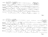
- FIG. 1 a schematic representation of an exemplary embodiment of a master-slave system 100 is shown.
- the master-slave system 100 comprises a master unit 1 and four exemplary fans slave A, slave B, slave C and slave D.
- any suitable number of slave units 2 can be provided, wherein the slave units 2 with the Master unit 1 are connected to each other via a bus system 3 and can communicate via the bus line 3a of the bus system 3, as soon as a unique address is present.
- each slave unit 2 has a bus interface 3b, which is connected to the bus interface 1a of the master unit 1.
- each slave unit 2 has an address input 2a and an address output 2b.
- the slave units 2 are connected in series via the address output or the address input of the respectively adjacent slave unit 2 via an address data line 4 (short address line 4).
- the address line 4 is a separate line from the bus 3a.
- the first slave unit 2 (slave A) is not connected via the address line 4 to the master unit 1, but only via the bus line 3a.
- the master-slave system 100 is configured so that the master unit 1 on the one hand for activation and on the other hand for carrying out the dynamic addressing of slave addresses A 1 , ..., A i , ..., to broadcast commands can send to the slave units 2.
- the address of the slave units 2 can assume an arbitrary value, which is shown in FIGS. 2 and 3 marked with an "X".
- this dynamic process continues to the last slave unit. Like in the FIG. 2 is visible, this then has the value 4.
- the slave unit changes its address value n times at the nth position (including the start address).
- FIG. 3 an example is shown how at the output of slave A and at the input of slave B an interference signal with the address value "3" is present.
- this dynamic addressing adulteration according to the present invention is automatically remedied again.
- the interference signal is sent to all slave units 2 passed on delayed. Consequently, the fault is present at each slave only as long as the length of the injected interference signal. Then the influence of the disturbance is eliminated again.
- the last slave unit 2 has at its output 2b a connection via an address line 5 to the master unit 1 in order to detect the completion of the addressing. As soon as a stable address state exists, the master unit 1 sends via the bus line 3a of the bus system 3 another broadcast command "Disable address function". Thereafter, the slave units 2 have a fixed address address that can be addressed via the bus system.
- the invention is not limited in its execution to the above-mentioned preferred embodiments. Rather, a number of variants is conceivable, which makes use of the illustrated solution even with fundamentally different types of use. All disclosed features can be used in any combination as far as this is technically possible.
Landscapes
- Engineering & Computer Science (AREA)
- Theoretical Computer Science (AREA)
- General Engineering & Computer Science (AREA)
- Physics & Mathematics (AREA)
- General Physics & Mathematics (AREA)
- Computer Networks & Wireless Communication (AREA)
- Signal Processing (AREA)
- Computer Hardware Design (AREA)
- Small-Scale Networks (AREA)
- Information Transfer Systems (AREA)
Abstract
Description
- Die Erfindung betrifft ein dynamisch adressierbares Master-Slave-System und ein Verfahren zum dynamischen Adressieren von Slave-Einheiten.
- Bussysteme verschiedenster Art sind seit langem bekannt. Die der vorliegenden Erfindung zugrunde liegenden Master/Slave Bussysteme besitzen meist die Eigenschaft, dass alle Slaves eindeutige Adressen haben müssen, um individuell angesprochen werden zu können. Mittels Bussystem können dadurch einzelne Slaves individuell angesprochen werden, wobei darüber die Einstellungen der Slaves geändert werden können oder Zustandsinformationen vom Slave abgefragt werden können. Bussysteme verschiedenster Art wie z. B. Master-Slave-Bussysteme sind im Stand der Technik seit Langem bekannt.
- Bei vielen Master-Slave-Bussystemen sind die Slave-Einheiten des Systems durch die Master-Einheit individuell identifizierbar und ansprechbar. Dadurch ist eine Master-Einheit beispielsweise in der Lage, bei einer bestimmte Slave-Einheit eine von dieser Slave-Einheit angesteuerte Systemkomponente zu betätigen, oder empfangene Meldungen einer bestimmten Slave-Einheit- und damit einer bestimmten Systemkomponente zuzuordnen. Um eine solche Funktionalität zu gewährleisten, benötigt die Slave-Einheit zum Einen eine systemweit eindeutige Adresse; zum Anderen muss die eindeutige Adresse sowie die Zugehörigkeit der Slave-Einheit zu einer Systemkomponente oder ihre Position im Bus-system der Master-Einheit bekannt sein.
- Konventionell wird dies beispielsweise erreicht, indem bei der Initialisierung eines Bussystems eine Adressier- oder Orientierungsphase durchgeführt wird. In dieser Phase werden den Slave-Einheiten zum Beispiel in einer bestimmten Reihenfolge Systemadressen zugeteilt, oder der Master-Einheit wird Gelegenheit gegeben, nacheinander gespeicherte Gerätekennungen von einzelnen Slave-Einheiten an verschiedenen Positionen abzufragen. Beispielsweise wird eine Adressvergabe an die Slave-Einheiten manuell durchgeführt, indem die vorhandenen Slaves in einer definierten Reihenfolge nacheinander einzeln an das Bussystem angeschlossen oder mittels eines manuell betätigten Schalters nacheinander einzeln zur Adressierung freigegeben werden: Weil nur eine definierte, manuell ausgewählte Slave-Einheit an die Busleitung angeschlossen bzw. zur Adressierung freigegeben ist, kann die Master-Einheit durch das Ausgeben eines - eigentlich an alle am Bussystem hängenden Slave-Einheiten gerichteten - Broadcast-Befehls auf dem Bus eine eindeutige Adresse an diese einzelne Slave-Einheit vergeben. Auf Grund der definierten Reihenfolge, in der die Slave-Einheiten adressiert werden, kennt die Master-Einheit nach der Adressvergabe auch die relative Position der einzelnen Slave-Einheiten im System. Solche manuellen Verfahren sind jedoch zeitaufwändig und durch Einbindung einer Person fehleranfällig.
- Einen automatisierten Adressiervorgang schlägt die
DE 103 36 301 A1 vor. Aus derEP 2 287 689 EP ist ein Bus-basierendes Adressierverfahren von Slave-Einheiten bekannt. Die im Stand der Technik bekannten Lösungen benötigen zur Umsetzung des Adressierverfahrens und zur Umsetzung der Busarchitektur entsprechende Systemkomponenten die zusätzliche Kosten verursachen und auch Bauraum benötigen. Auch beim Austausch von einer mit einem Slave verbundenen Anlagenkomponente, wie zum Beispiel einem Lüfter, sind entsprechende Maßnahmen notwendig die Adressvergabe anschließend zu konfigurieren. - In der
DE 10 2014 117 797.5 A1 wird daher ein Master-Slave-System vorgeschlagen, umfassend eine Master-Einheit mit einem Digitalausgang zur Bereitstellung eines Signals oder eine serielle Signalfolge von Signalen und mehrere Slave-Einheiten, wobei die Slave-Einheiten jeweils einen digitalen seriellen Speicher mit einer Größe von einem Bit aufweisen und jeweils einen Eingang und einen Ausgang aufweisen, wobei die Slave-Einheiten über die Eingänge und die Ausgänge über eine Signalleitung seriell miteinander verbunden sind und wobei der Eingang einer ersten Slave-Einheit über die Signalleitung mit dem Digitalausgang der Master-Einheit verbunden ist. Das Master-Slave-System ist so konfiguriert, dass am Eingang der Slave-Einheit ein vom Digitalausgang bereitgestelltes Signal (Signalwechsel) einer seriellen Signalfolge detektiert wird, um die Adresse der entsprechenden Slave-Einheit jeweils um den Wert "1" zu erhöhen, den Signalwechsel im Speicher zu hinterlegen und ein zum Inhalt des Speichers korrespondierendes Signal am Ausgang des Speichers auszugeben. - Nachteilig bei diesem Adressierungsverfahren ist, dass zur Adressierung über Schieberregister ein Taktsignal vom Master erforderlich ist und die Adressierung nicht quasi-automatisch nach dem Systemstart abläuft.
- Aus der
US 8 856 413 B2 ist eine dynamisch adressierbare Slave-Einheit, umfassend ein Interface-Bus, eine Freigabeschaltung mit einem Schalter und zwei Steueranschlüssen bekannt, die über die Freigabeschaltung verbunden sind. Das System ist so konfiguriert, dass die Adresszuordnung nur dann möglich ist, wenn das Bus-Interface-Steuersignal an einem der Anschlüsse anliegt und sofern zur Steuerung der Freisetzung der Signalschalter offen ist. Andernfalls sperrt die Freigabeschaltung die Slave-Einheit. Nachteilig ist bei diesem Verfahren, dass eine spezielle Schaltung erforderlich ist, um die Adressierung vorzunehmen. - Es besteht im Übrigen ein Bedürfnis danach, die Adressierung in einer aufsteigenden Adressreihenfolge vorzunehmen, sowie Fehler durch Störungen bei der Adressübergabe automatisch (d. h. ohne manuellen Eingriff) zu eliminieren.
- Vor diesem Hintergrund ist es Aufgabe der vorliegenden Erfindung, vorbesagte Nachteile zu überwinden und ein verbessertes Verfahren zum dynamischen Adressieren von Slave-Einheiten sowie dynamisch adressierbares Master-Slave-System bereitzustellen, welches auf eine Bus-Architektur für die Adressvergabe verzichten kann und einfach in der Implementierung und Handhabung ist und nach dem Start des Systems quasi-automatisch abläuft.
- Diese Aufgabe wird gelöst mit einem dynamisch adressierbaren Master-Slave-System mit den Merkmalen von Anspruch 1 sowie einem Verfahren zum dynamischen Adressieren von Slave-Einheiten mit den Merkmalen von Anspruch 10. Grundgedanke der vorliegenden Erfindung ist es, das Master-Slave-System so zu konfigurieren, dass zum Zeitpunkt der Einleitung der Adressierung der Slave-Einheiten der Master zunächst eine identische Startwert-Adresse über einen Broadcast-Befehl an alle Slaves übergibt. Dadurch aktiviert der Master die Adressierung über den Broadcast-Befehl bei allen Slaves.
- Die Slaves sind über eine Adressierleitung seriell miteinander verbunden. Über die Adressierleitung können Signale übertragen werden, die eine Information über die Adresse enthalten. Die Slaves sind hierzu mit einem Adresseingang zum Empfang der Adresse vom vorhergehenden Slave und einem Adressausgang zur Weiterleitung seiner Adresse an den nächsten Slave verbunden.
- Sobald ein Slave ein eindeutiges Signal an seinem Eingang erkannt hat, ermittelt er aus dem Signal die Adresse des vorhergehenden Slaves und setzt seine eigene Adresse auf den um "1" erhöhten Wert. Diese eigene Adresse wird an den Ausgang dieser Slave-Einheit und damit an den Eingang der nächsten Slave-Einheit gegeben.
- Erfindungsgemäß ist ferner vorgesehen, dass der erste Slave in der seriellen Kette von Slaves seine Adresse vom Master über einen Broadcast - Befehl zugewiesen bekommt und an seinem Adresseingang kein Signal empfangen wird. Somit ändert er seine Adresse im weiteren Verlauf nicht mehr.
- Alternativ kann der Master mit dem Adressiereingang des ersten Slaves verbunden werden und diesem seine Adresse über diese Verbindung zuweisen.
- Ab diesem Zeitpunkt wird an den Ausgängen der Slaves die jeweils neue Adresse ausgegeben. Die nachfolgenden Slaves reagieren auf die geänderte Vorgabe und ändern jeweils erneut ihre Adresse. Der dynamische Adressiervorgang wird solange fortgesetzt, bis das System in einen stabilen Adress-Zustand aller Slave-Einheiten gebracht wurde. In diesem Zustand haben alle Slaves eine unterschiedliche Adresse und können alsdann über die Bus-Leitung individuell angesprochen werden.
- Gemäß der vorliegenden Erfindung werden die Adressen in aufsteigender Reihenfolge vergeben. Der stabile Adress-Zustand kann z. B. dadurch festgestellt werden, indem eine Adressierleitung des letzten Slaves in der Reihe der seriell verschalteten Slaves an den Master zurückgeführt wird und erfindungsgemäß z. B. eine definierte Zeitspanne ohne Adressänderung den stabilen Zustand repräsentiert.
- Nachdem der stabile System-Zustand erreicht ist, deaktiviert der Master die Adressierung wieder über einen Befehl an alle Slaves über die Busleitung.
- Erfindungsgemäß wird daher ein dynamisch adressierbares Master-Slave-System umfassend eine Master-Einheit und Anzahl an n Slave-Einheiten vorgeschlagen, wobei die Slave-Einheiten (Slaves) mit der Master-Einheit über ein Bus-System miteinander verbunden sind und von der Master-Einheit über die Busleitung des Bus-Systems zu Beginn der Adressierung wenigstens einen Broadcast-Befehl empfangen können. Die Slave-Einheiten weisen jeweils einen Adresseingang und einen Adressausgang auf und sind über eine von der Busleitung getrennte d. h. separate Adressleitung seriell miteinander verbunden, wobei das Master-Slave-System so konfiguriert ist, dass die Master-Einheit einerseits zur Aktivierung und andererseits zur Durchführung des dynamischen Adressiervorgangs von Slave-Adressen Broadcast-Befehle gleichzeitig an die Slave-Einheiten senden kann.
- In einer bevorzugten Ausführungsform der Erfindung ist daher vorgesehen, dass zur Aktivierung des dynamischen Adressiervorgangs ein erster Broadcast-Befehls an alle Slave-Einheiten erfolgt, indem diesen, insbesondere der ersten Slave-Einheit, eine identische Startwert-Adresse über die Busleitung zugewiesen wird. In diesem Zustand besitzen alle Slaves die gleiche Startadresse. Bevorzugt stellen die Slaves z. B. Ventilatoren dar, die über eine Busleitung miteinander verbunden sind.
- Mit Vorteil ist weiter vorgesehen, dass der Adressausgang der n-1 Slave-Einheiten mit dem Adresseingang der jeweils seriell benachbarten nächsten Slave-Einheit verbunden ist.
- Nach der Aktivierung erfolgt in einer bevorzugten Ausgestaltung die Durchführung des dynamischen Adressiervorgangs mittels des ersten oder mittels eines weiteren Broadcast-Befehls an alle Slave-Einheiten, wobei die Adressvergabe der 2-ten bis n-ten Slave-Einheiten nicht mehr über die Busleitung, sondern über die Adressleitung erfolgt, während die erste Slave-Einheit ihre Adresse allerdings nicht mehr ändert.
- In vorteilhafter Weise ist daher die erste Slave-Einheit eingangsseitig nicht mit der Adressleitung verbunden und erhält diese Slave-Einheit ihre Adresse über den Broadcast-Befehl über die Busleitung. In einer alternativen Ausgestaltung kann die erste Slave-Einheit Ihre Adresse über eine Adressleitung vom Master beziehen.
- Die Slave-Adresse der i-ten Slave-Einheit erhöht den am Eingang detektierten Adresswert jeweils um den Wert "1", sobald ein Signal über die Adressleitung am Adresseingang von der benachbarten (i-1)-ten Slave-Einheit empfangen wird. Dieser Adresswert wird dann am Ausgang der betroffenen Slave-Einheit weitergegeben.
- Mit Vorteil ist daher vorgesehen, dass nach dem Erhöhen der Slave-Adresse der i-ten Slave-Einheit ein Signal am Adressausgang zur benachbarten (i+1)-ten Slave-Einheit und zwar zu dessen Adresseingang geführt wird und der dynamische Adressiervorgang so lange wiederholt wird, bis an der n-ten Slave-Einheit n-1 Adressänderungen ausgehend von dem Startwert vollzogen wurden (sofern kein Fehlersignal vorlag).
- In einer weiter bevorzugten Ausgestaltung der Erfindung ist vorgesehen, dass der Ausgang der letzten Slave-Einheit in der seriellen Anordnung mit der Master-Einheit über eine Rückleitung verbunden ist, um dadurch das Ende der dynamischen Adressierung anzuzeigen, sobald ein stabiler Adress-Zustand erreicht ist.
- Ein weiterer Aspekt der vorliegenden Erfindung betrifft das Verfahren zum dynamischen Adressieren von n Slave-Einheiten eines wie zuvor beschriebenen Master-Slave-Systems mit den folgenden Schritten:
- die Aktivierung des dynamischen Adressiervorgangs wird mittels eines Broadcast-Befehls an alle Slave-Einheiten durchgeführt;
- allen Slave-Einheiten, insbesondere der ersten Slave-Einheit, wird über eine Busleitung eine identische Startwert-Adresse zugewiesen;
- Durchführen des Adressiervorgangs durch Erhöhen des gerade aktuellen Adresswertes der jeweiligen Slave-Adresse (Ai) der i-ten Slave-Einheit um den Wert "1" gegenüber dem Eingangsadresswert sobald ein Signal am Adresseingang der benachbarten (i-1)-ten Slave-Einheit (2) erhalten wird;
- nach dem Erhöhen der Slave-Adresse der i-ten Slave-Einheit wird jeweils ein Signal am Adressausgang zur benachbarten (i+1)-ten Slave-Einheit zu dessen Adresseingang geführt und der dynamische Adressiervorgang so lange wiederholt, bis an der n-ten Slave-Einheit n-1 Adressänderungen ausgehend von dem Startwert vollzogen wurden. Besonders vorteilhaft ist die Durchführung des Verfahrens, wenn die Signalweitergabe beim Adressierprozess über die Adressleitung von der einen zur nächsten Slave-Einheit mittels Analogsignalen, bitcodierten digitalen Signalen, Signalpulsfolgen oder mittels optischer Signale erfolgt.
- Andere vorteilhafte Weiterbildungen der Erfindung sind in den Unteransprüchen gekennzeichnet bzw. werden nachstehend zusammen mit der Beschreibung der bevorzugten Ausführung der Erfindung anhand der Figuren näher dargestellt.
- Es zeigen:
- Fig. 1
- eine schematische Darstellung eines beispielhaften Ausführungsbeispiels eines Master-Slave-Systems;
- Fig. 2
- eine schematische Darstellung der Adressvergabe bei vier Slave-Einheiten und
- Fig. 3
- eine schematische Darstellung der Adressvergabe ähnlich der
Figur 2 jedoch mit einem Störsignal. - Im Folgenden wird die Erfindung anhand eines Ausführungsbeispiels mit Bezug auf die
Figuren 1 bis 3 näher beschrieben, wobei gleiche Bezugszeichen auf gleiche funktionale und/oder strukturelle Merkmale hinweisen. - In der
Figur 1 ist eine schematische Darstellung eines beispielhaften Ausführungsbeispiels eines Master-Slave-Systems 100 gezeigt. Das Master-Slave-System 100 umfasst eine Master-Einheit 1 und vier beispielhafte Ventilatoren Slave A, Slave B, Slave C und Slave D. Grundsätzlich kann jede geeignete Anzahl an Slave-Einheiten 2 vorgesehen werden, wobei die Slave-Einheiten 2 mit der Master-Einheit 1 über ein Bus-System 3 miteinander verbunden sind und über die Bus-Leitung 3a des Bus-Systems 3 kommunizieren können, sobald eine eindeutige Adresse vorhanden ist. - Jede Slave-Einheit 2 weist hierzu eine Bus-Schnittstelle 3b auf, die mit der Bus-Schnittstelle 1a der Master-Einheit 1 verbunden sind.
- Ferner weist jede Slave-Einheit 2 einen Adresseingang 2a und einen Adressausgang 2b auf. Die Slave-Einheiten 2 sind über den Adressausgang bzw. den Adresseingang der jeweils benachbarten Slave-Einheit 2 über eine Adressdatenleitung 4 (kurz Adressleitung 4) seriell miteinander verbunden.
- Wie in der
Figur 1 zu erkennen ist, ist die Adressleitung 4 eine von der Busleitung 3a getrennte Leitung. Die erste Slave-Einheit 2 (Slave A) ist allerdings nicht über die Adressleitung 4 mit der Master-Einheit 1 verbunden, sondern nur über die Busleitung 3a. - Das Master-Slave-System 100 ist dabei so konfiguriert, dass die Master-Einheit 1 einerseits zur Aktivierung und andererseits zur Durchführung des dynamischen Adressiervorgangs von Slave-Adressen A1,..., Ai,..., An Broadcast-Befehle an die Slave-Einheiten 2 senden kann. Wie in der
Figur 2 ersichtlich, erfolgt zunächst ein Broadcast Befehl "Setze Adresse = 1" an alle Slave-Einheiten 2. Vorher kann die Adresse der Slave-Einheiten 2 einen beliebigen Wert annehmen, was in denFiguren 2 und 3 mit einem "X" gekennzeichnet wurde. - In einem weiteren Broadcast Befehl "Adressfunktion aktivieren" erfolgt die Aktivierung zur Durchführung der Adressvergabe, die danach quasi-automatisch abläuft.
- Bei den vier dargestellten Slave-Einheiten 2, haben nach dem Broadcast Befehl "Setze Adresse = 1" alle vier Slave-Einheiten 2 den Adresswert "1". Nachdem allerdings am Eingang der zweiten Slave-Einheit 2 (Slave B) ein Adresssignal mit dem Adresswert "1" detektiert wird, erhöht sich automatisch die Adresse um den Wert "+1", so dass die zweite Slave-Einheit 2 danach den Adresswert "2" aufweist.
- Gleichermaßen pflanzt sich dieser dynamische Prozess bis zur letzten Slave-Einheit fort. Wie in der
Figur 2 ersichtlich ist, hat diese dann den Wert 4. Im Normalfall (ohne Störsignale) ändert die Slave-Einheit an der n-ten Position damit n-Mal ihren Adresswert (einschließlich der Startadressierung). - In der
Figur 3 ist ein Beispiel gezeigt, wie am Ausgang von Slave A und am Eingang von Slave B ein Störsignal mit dem Adresswert "3" anliegt. Allerdings wird diese Störeinfluss beim dynamischen Adressieren gemäß der vorliegenden Erfindung wieder automatisch bereinigt. Das Störsignal wird an alle Slave-Einheiten 2 zeitlich verzögert weitergegeben. Die Störung liegt demzufolge an jedem Slave nur solange an, wie die Länge des eingekoppelten Störsignals ist. Danach ist der Einfluss der Störung wieder eliminiert. - Die letzte Slave-Einheit 2 hat an ihrem Ausgang 2b eine Verbindung über eine Adressleitung 5 zur Master-Einheit 1, um den Abschluss der Adressierung zu detektieren. Sobald ein stabiler Adress-Zustand besteht versendet die Master-Einheit 1 über die Busleitung 3a des Bus-Systems 3 einen weiteren Broadcast Befehl "Adressfunktion deaktivieren". Danach besitzen die Slave-Einheiten 2 eine feste ansprechbare Adresse, die über das Bus-System angesprochen werden kann.
- Die Erfindung beschränkt sich in ihrer Ausführung nicht auf die vorstehend angegebenen bevorzugten Ausführungsbeispiele. Vielmehr ist eine Anzahl von Varianten denkbar, welche von der dargestellten Lösung auch bei grundsätzlich anders gearteten Ausführungen Gebrauch macht. Alle offenbarten Merkmale sind in beliebigen Kombinationen verwendbar soweit dies technisch möglich ist.
Claims (11)
- Verfahren zum dynamischen Adressieren von n Slave-Einheiten (2) eines Master-Slave-Systems (100) umfassend eine Master-Einheit (1) und eine Mehrzahl von Slave-Einheiten (2), wobei die Slave-Einheiten (2) mit der Master-Einheit (1) über ein Bus-System (3) miteinander verbunden sind und von der Master-Einheit (1) über die Busleitung (3a) des Bus-Systems (3) wenigstens einen Broadcast-Befehl (B) empfangen können, wobei das Master-Slave-System (100) so konfiguriert ist, dass die Master-Einheit (2) einerseits zur Aktivierung und andererseits zur Durchführung des dynamischen Adressiervorgangs von Slave-Adressen (A1,..., Ai,..., An) entsprechende Broadcast-Befehle (B) an die Slave-Einheiten (2) senden kann und wobei die Slave-Einheiten (2) jeweils einen Adresseingang (2a) und einen Adressausgang (2b) aufweisen und über eine von der Busleitung (3a) getrennte Adressleitung (4) seriell miteinander verbunden sind.
mit den folgenden Schritten:a. die Aktivierung des dynamischen Adressiervorgangs wird mittels eines Broadcast-Befehls (B) an alle Slave-Einheiten (2) durchgeführt;b. allen Slave-Einheiten (2) wird über eine Busleitung (3a) eine identische Startwert-Adresse (SA) zugewiesen;c. Durchführen des Adressiervorgangs durch Erhöhen des eingangsseitigen Adresswertes der jeweiligen Slave-Adresse (Ai) der i-ten Slave-Einheit (2) um den Wert "1" sobald ein Signal am Adresseingang (2a) von der benachbarten (i-1)-ten Slave-Einheit (2) erhalten wird;d. nach dem Erhöhen der Slave-Adresse (Ai) der i-ten Slave-Einheit (2) wird jeweils ein Signal am Adressausgang (2b) zur benachbarten (i+1)-ten Slave-Einheit (2) zu dessen Adresseingang (2a) geführt und der dynamische Adressiervorgang so lange wiederholt, bis an der n-ten Slave-Einheit (2) die letzte Adressänderung vollzogen wurden. - Verfahren nach Anspruch 2, dadurch gekennzeichnet, dass die n-te (letzte) Slave-Einheit (2) nach ihrer n-ten Adressierung an ihrem Ausgang (2b) über eine Rückleitung (5) ein Signal an die Master-Einheit (1) übermittelt, wodurch die Master-Einheit (1) den Abschluss des Adressierverfahrens detektiert.
- Verfahren nach Anspruch 2 oder 3, dadurch gekennzeichnet, dass die Signalweitergabe beim Adressierprozess über die Adressleitung (4) von der einen zur nächsten Slave-Einheit (2) mittels Analogsignalen, bitcodierten digitalen Signalen, Signalpulsfolgen oder mittels optischer Signale.
- Verfahren nach einem der vorhergehenden Ansprüche, dadurch gekennzeichnet, dass die Aktivierung des dynamischen Adressiervorgangs mittels eines ersten Broadcast-Befehls (B) an alle Slave-Einheiten (2) erfolgt, indem diesen eine identische Startwert-Adresse (SA) über die Busleitung (3a) zugewiesen wird.
- Verfahren nach einem der vorhergehenden Ansprüche, dadurch gekennzeichnet, dass n-Slave-Einheiten (2) vorgesehen sind, wobei der Adressausgang (2b) der n-1 Slave-Einheiten (2) mit dem Adresseingang der jeweils seriell benachbarten nächsten Slave-Einheit (2) verbunden ist.
- Verfahren nach einem der vorhergehenden Ansprüche, dadurch gekennzeichnet, dass nach der Aktivierung die Durchführung des dynamischen Adressiervorgangs mittels des ersten oder eines weiteren Broadcast-Befehls (B) an alle Slave-Einheiten (2) erfolgt, wobei die Adressvergabe der 2-ten bis n-ten Slave-Einheiten (2) über die Adressleitung (4) erfolgt.
- Verfahren nach einem der vorhergehenden Ansprüche, dadurch gekennzeichnet, dass sobald die Slave-Adresse (Ai) der i-ten Slave-Einheit (2) ein Signal am Adresseingang (2a) der benachbarten (i-1)-ten Slave-Einheit (2) erhält und seinen aktuellen Adresswert dadurch anpasst, dass der Adresswert am Adresseingang (2a) jeweils um den Wert "1" erhöht wird.
- Verfahren nach einem der vorhergehenden Ansprüche, dass nach dem Erhöhen der Slave-Adresse (Ai) der i-ten Slave-Einheit (2) ein Signal am Adressausgang (2b) zur benachbarten (i+1)-ten Slave-Einheit (2) zu dessen Adresseingang (2a) geführt wird und der dynamische Adressiervorgang so lange wiederholt wird, bis an der n-ten Slave-Einheit (2) n-1 Adressänderungen ausgehend von dem Startwert (SA) vollzogen wurden.
- Verfahren nach einem der vorhergehenden Ansprüche, dadurch gekennzeichnet, dass die erste Slave-Einheit (2) nicht mit der Adressleitung (4) verbunden ist und seine Adresse über den Broadcast-Befehl (B) über die Busleitung (3a) erhält.
- Verfahren nach einem der vorhergehenden Ansprüche, dadurch gekennzeichnet, dass die erste Slave-Einheit (2) über eine Adressleitung (4) mit der Master-Einheit (1) verbunden ist, um seine Adresse über die Adressleitung (4) von der Master-Einheit (2) zu beziehen,
- Verfahren nach einem der vorhergehenden Ansprüche, dadurch gekennzeichnet, dass der Ausgang der letzten Slave-Einheit (2) in der seriellen Anordnung mit der Master-Einheit (1) über eine Rückleitung (5) verbunden ist.
Applications Claiming Priority (1)
| Application Number | Priority Date | Filing Date | Title |
|---|---|---|---|
| DE102015113491.8A DE102015113491A1 (de) | 2015-08-14 | 2015-08-14 | Dynamikadressierung |
Publications (2)
| Publication Number | Publication Date |
|---|---|
| EP3131016A1 true EP3131016A1 (de) | 2017-02-15 |
| EP3131016B1 EP3131016B1 (de) | 2020-09-02 |
Family
ID=56852050
Family Applications (1)
| Application Number | Title | Priority Date | Filing Date |
|---|---|---|---|
| EP16181483.5A Not-in-force EP3131016B1 (de) | 2015-08-14 | 2016-07-27 | Dynamikadressierung |
Country Status (3)
| Country | Link |
|---|---|
| US (1) | US10089273B2 (de) |
| EP (1) | EP3131016B1 (de) |
| DE (2) | DE102015113491A1 (de) |
Families Citing this family (21)
| Publication number | Priority date | Publication date | Assignee | Title |
|---|---|---|---|---|
| DE102015121288A1 (de) * | 2015-12-07 | 2017-06-08 | Eaton Electrical Ip Gmbh & Co. Kg | Busanordnung und Verfahren zum Betreiben einer Busanordnung |
| DE102016103928A1 (de) * | 2016-03-04 | 2017-09-07 | Eaton Electrical Ip Gmbh & Co. Kg | Busanordnung und Verfahren zum Betreiben einer Busanordnung |
| DE102017101869B4 (de) | 2017-01-31 | 2024-07-25 | Jungheinrich Aktiengesellschaft | Ladegerät für mehrere, jeweils mit einer Feldbus-Schnittstelle ausgestattete Leistungsmodule |
| DE102017105822B4 (de) * | 2017-03-17 | 2022-11-10 | Feig Electronic Gmbh | Verfahren zur Zuordnung von Adressen bei Modulen eines Systems bestehend aus wenigstens zwei RFID-Antennen sowie Gate-Antennenanordnung bestehend aus wenigstens zwei RFID-Antennen |
| DE102017208823A1 (de) * | 2017-05-24 | 2018-11-29 | Wago Verwaltungsgesellschaft Mbh | Initialisierung eines Lokalbusses |
| US10169274B1 (en) * | 2017-06-08 | 2019-01-01 | Qualcomm Incorporated | System and method for changing a slave identification of integrated circuits over a shared bus |
| DE102018001574B4 (de) * | 2018-02-28 | 2019-09-05 | WAGO Verwaltungsgesellschaft mit beschränkter Haftung | Master-Slave Bussystem und Verfahren zum Betrieb eines Bussystems |
| JP6688334B2 (ja) * | 2018-03-27 | 2020-04-28 | 矢崎総業株式会社 | ネットワークノード、ネットワーク通信システム及びネットワーク通信方法 |
| US11063850B2 (en) * | 2018-08-29 | 2021-07-13 | Ati Technologies Uls | Slave-to-master data and out-of-sequence acknowledgements on a daisy-chained bus |
| EP3780558B1 (de) * | 2019-08-14 | 2025-02-19 | Schneider Electric Industries SAS | Adressierung von slave-vorrichtungen mittels iterativer leistungsaktivierung |
| FR3102582B1 (fr) * | 2019-10-25 | 2021-10-15 | Sc Optima | ATTRIBUTION AUTOMATIQUE D’ADRESSES PHYSIQUES ET déterminATION D’une position relative d’une pluralité de calculateurs périphériques EN RESEAU |
| KR102256670B1 (ko) * | 2019-11-06 | 2021-05-27 | (주)로보티즈 | 효율적인 통신 버스 중재 시스템 및 방법 |
| US11748261B2 (en) | 2020-07-24 | 2023-09-05 | Eaton Intelligent Power Limited | Automatic address generation for modular electronic devices |
| DE102021105919A1 (de) | 2021-03-11 | 2022-09-15 | Ebm-Papst Mulfingen Gmbh & Co. Kg | Adressierbares Master-Slave-System sowie Verfahren zum Adressieren von Slave-Einheiten |
| EP4175238B1 (de) | 2021-10-27 | 2026-02-18 | Schneider Electric Industries SAS | Konfiguration von slave-vorrichtungen in einem industriellen netzwerksystem |
| CN114500147B (zh) * | 2021-12-29 | 2023-12-26 | 深圳市英威腾电气股份有限公司 | 分配站号的方法、装置、电子设备及存储介质 |
| GB2621616A (en) * | 2022-08-17 | 2024-02-21 | Eaton Intelligent Power Ltd | Bus arrangement and method for operating a bus arrangement |
| JP2025056453A (ja) * | 2023-09-27 | 2025-04-08 | 旭化成エレクトロニクス株式会社 | スレーブデバイス、通信システム、撮像装置、マスタデバイス、及びデータ通信方法 |
| CN117527762B (zh) * | 2023-11-27 | 2026-04-17 | 南京智睿能源互联网研究院有限公司 | 一种基于串口modbus通讯协议的自识别方法及系统 |
| DE102024203951B4 (de) * | 2024-04-26 | 2025-12-04 | Aumovio Autonomous Mobility Germany Gmbh | Verfahren zur Positionserkennung eines Busteilnehmers, Bussystem sowie Steuereinrichtung |
| TWI903964B (zh) * | 2025-01-08 | 2025-11-01 | 茂達電子股份有限公司 | 資料傳輸動態定址系統 |
Citations (6)
| Publication number | Priority date | Publication date | Assignee | Title |
|---|---|---|---|---|
| DE10336301A1 (de) | 2003-07-31 | 2005-03-10 | Ego Elektro Geraetebau Gmbh | Verfahren zur dynamischen Vergabe von Adressen sowie zugehörige Verwendung für Heizeinrichtungen |
| WO2009040298A1 (de) * | 2007-09-20 | 2009-04-02 | Insta Elektro Gmbh | Verfahren zum betrieb eines bussystems sowie bussystem |
| EP2287689A1 (de) | 2009-07-27 | 2011-02-23 | Ziehl-Abegg AG | Vorrichtung und Verfahren zur Adressierung einer Slave-Einheit |
| US20120072626A1 (en) * | 2010-09-22 | 2012-03-22 | Microsoft Corporation | Automatic Addressing Protocol for a Shared Bus |
| US8631179B1 (en) * | 2011-09-25 | 2014-01-14 | Maxim Integrated Products, Inc. | System and method for automatically assigning bus addresses to slave devices |
| DE102014117797A1 (de) | 2014-10-10 | 2016-04-14 | Ebm-Papst Mulfingen Gmbh & Co. Kg | Dynamisch adressierbares Master-Slave-System sowie Verfahren zum dynamischen Adressieren von Slave-Einheiten |
Family Cites Families (10)
| Publication number | Priority date | Publication date | Assignee | Title |
|---|---|---|---|---|
| DE4119584C3 (de) * | 1990-07-13 | 1995-08-03 | Abb Patent Gmbh | Elektronische Einrichtung mit Steckbaugruppen |
| US5204669A (en) * | 1990-08-30 | 1993-04-20 | Datacard Corporation | Automatic station identification where function modules automatically initialize |
| US6820148B1 (en) * | 2000-08-17 | 2004-11-16 | Sandisk Corporation | Multiple removable non-volatile memory cards serially communicating with a host |
| US20080040515A1 (en) * | 2003-12-22 | 2008-02-14 | Ralf Schaetzle | Method and System for Automated Configuring of a Hart Multi-Drop System |
| CN101315617A (zh) * | 2007-06-01 | 2008-12-03 | 鸿富锦精密工业(深圳)有限公司 | 总线电路装置 |
| US20100185784A1 (en) * | 2007-07-20 | 2010-07-22 | Nxp B.V. | Automatic address assignment for communiation bus |
| JP2009194731A (ja) * | 2008-02-15 | 2009-08-27 | Fujitsu Ltd | スレーブ装置、並びに、データ伝送システム及び方法 |
| US20100122003A1 (en) * | 2008-11-10 | 2010-05-13 | Nec Laboratories America, Inc. | Ring-based high speed bus interface |
| US8378806B2 (en) * | 2010-09-17 | 2013-02-19 | Simplexgrinnell Lp | Pseudo non-addressable alarm system |
| DE102014008335A1 (de) * | 2014-06-12 | 2015-05-07 | Diehl Aerospace Gmbh | Beleuchtungsanordnung für einen Innenraum eines Flugzeugs, Flugzeug mit der Beleuchtungsanordnung sowie Verfahren zum Konfiguieren der Beleuchtungsanordnung |
-
2015
- 2015-08-14 DE DE102015113491.8A patent/DE102015113491A1/de not_active Withdrawn
-
2016
- 2016-07-27 DE DE202016104113.9U patent/DE202016104113U1/de not_active Expired - Lifetime
- 2016-07-27 EP EP16181483.5A patent/EP3131016B1/de not_active Not-in-force
- 2016-08-12 US US15/235,135 patent/US10089273B2/en active Active
Patent Citations (7)
| Publication number | Priority date | Publication date | Assignee | Title |
|---|---|---|---|---|
| DE10336301A1 (de) | 2003-07-31 | 2005-03-10 | Ego Elektro Geraetebau Gmbh | Verfahren zur dynamischen Vergabe von Adressen sowie zugehörige Verwendung für Heizeinrichtungen |
| WO2009040298A1 (de) * | 2007-09-20 | 2009-04-02 | Insta Elektro Gmbh | Verfahren zum betrieb eines bussystems sowie bussystem |
| EP2287689A1 (de) | 2009-07-27 | 2011-02-23 | Ziehl-Abegg AG | Vorrichtung und Verfahren zur Adressierung einer Slave-Einheit |
| US8856413B2 (en) | 2009-07-27 | 2014-10-07 | Ziehl-Abegg Ag | Device and method for addressing a slave unit |
| US20120072626A1 (en) * | 2010-09-22 | 2012-03-22 | Microsoft Corporation | Automatic Addressing Protocol for a Shared Bus |
| US8631179B1 (en) * | 2011-09-25 | 2014-01-14 | Maxim Integrated Products, Inc. | System and method for automatically assigning bus addresses to slave devices |
| DE102014117797A1 (de) | 2014-10-10 | 2016-04-14 | Ebm-Papst Mulfingen Gmbh & Co. Kg | Dynamisch adressierbares Master-Slave-System sowie Verfahren zum dynamischen Adressieren von Slave-Einheiten |
Also Published As
| Publication number | Publication date |
|---|---|
| US10089273B2 (en) | 2018-10-02 |
| DE202016104113U1 (de) | 2016-08-16 |
| DE102015113491A1 (de) | 2017-02-16 |
| EP3131016B1 (de) | 2020-09-02 |
| US20170046292A1 (en) | 2017-02-16 |
Similar Documents
| Publication | Publication Date | Title |
|---|---|---|
| EP3131016B1 (de) | Dynamikadressierung | |
| EP3007387B1 (de) | Dynamisch adressierbares master-slave-system sowie verfahren zum dynamischen adressieren von slave-einheiten | |
| EP1309920B1 (de) | Adressvergabeverfahren für mindestens einen neu an ein bussystem angeschlossenen busteilnehmer | |
| DE3111555C2 (de) | Verfahren und Vorrichtung zur Informationsspeicherung unter Anwendung früherer Aufzeichnung | |
| EP4057596A1 (de) | Adressierbares master-slave-system sowie verfahren zum adressieren von slave-einheiten | |
| EP3047635B1 (de) | Feldbuskoppler zur anbindung von modulen an einen feldbus und verfahren zur adressierung derartiger module | |
| EP2645824B1 (de) | Verfahren zum Betreiben von Geräten in einem Beleuchtungssystem | |
| EP3251469B1 (de) | Verfahren zum betreiben von geräten in einem beleuchtungssystem | |
| DE1524181A1 (de) | Abrufsystem fuer Ein- und Ausgabegeraete einer Datenverarbeitungsanlage | |
| DE2321200A1 (de) | Einrichtung zur durchfuehrung boolescher verknuepfungen | |
| WO2011072958A1 (de) | Verfahren zum zuweisen einer polling-adresse an ein feldgerät | |
| DE102020200931A1 (de) | Steuerungssystem mit mehreren funktionsmodulen und adressierungsverfahren für dessen funktionsmodule | |
| DE19645057C2 (de) | Vorrichtung zur Selektion von Adressenwörtern mittels Demultiplex-Decodierung | |
| DE102014112901A1 (de) | Kommunikationseinrichtung, Kommunikationssystem und Verfahren zum synchronisierten Senden von Telegrammen | |
| EP2631810A1 (de) | Verfahren zur Vergabe von Teilnehmeradressen und modulares Peripheriesystem der Automatisierungstechnik | |
| DE19952883A1 (de) | Bussystem für eine Mehrzahl von Teilnehmern | |
| EP1612689B1 (de) | Steckplatzerkennung in einem Bussystem | |
| WO1997022057A1 (de) | Verfahren zur adresseinstellung an bussystemen mit paralleler verdrahtung und vorrichtung zur durchführung des verfahrens | |
| EP3523728B1 (de) | Befehls- und meldesystem für die automatisierungstechnik | |
| DE2402881B2 (de) | Fehlersichere elektronische signalvergleichsschaltung | |
| WO2005107173A1 (de) | Einrichtung zur adressvergabe in einem normierten feldbus-system | |
| DE10336807B4 (de) | Verfahren und Vorrichtung zur Erweiterung der Funktionalität einer seriellen Schnittstelle sowie ein das Verfahren verwendendes Mobilfunkgerät und ein die Vorrichtung umfassendes Mobilfunkgerät | |
| DE19957107B4 (de) | Verfahren zur Gewährleistung des Datenaustauschs zwischen mehreren Einrichtungen | |
| EP1612681B1 (de) | Steckplatzerkennung in einem Bussystem | |
| DE102023001048A1 (de) | Verfahren zum Betreiben eines Verbundes von elektronischen Recheneinrichtungen in einem Kraftfahrzeug, Computerprogrammprodukt, computerlesbares Speichermedium, Verbund von elektronischen Recheneinrichtungen sowie Kraftfahrzeug |
Legal Events
| Date | Code | Title | Description |
|---|---|---|---|
| PUAI | Public reference made under article 153(3) epc to a published international application that has entered the european phase |
Free format text: ORIGINAL CODE: 0009012 |
|
| STAA | Information on the status of an ep patent application or granted ep patent |
Free format text: STATUS: THE APPLICATION HAS BEEN PUBLISHED |
|
| AK | Designated contracting states |
Kind code of ref document: A1 Designated state(s): AL AT BE BG CH CY CZ DE DK EE ES FI FR GB GR HR HU IE IS IT LI LT LU LV MC MK MT NL NO PL PT RO RS SE SI SK SM TR |
|
| AX | Request for extension of the european patent |
Extension state: BA ME |
|
| STAA | Information on the status of an ep patent application or granted ep patent |
Free format text: STATUS: REQUEST FOR EXAMINATION WAS MADE |
|
| 17P | Request for examination filed |
Effective date: 20170802 |
|
| RBV | Designated contracting states (corrected) |
Designated state(s): AL AT BE BG CH CY CZ DE DK EE ES FI FR GB GR HR HU IE IS IT LI LT LU LV MC MK MT NL NO PL PT RO RS SE SI SK SM TR |
|
| STAA | Information on the status of an ep patent application or granted ep patent |
Free format text: STATUS: EXAMINATION IS IN PROGRESS |
|
| 17Q | First examination report despatched |
Effective date: 20190827 |
|
| GRAP | Despatch of communication of intention to grant a patent |
Free format text: ORIGINAL CODE: EPIDOSNIGR1 |
|
| STAA | Information on the status of an ep patent application or granted ep patent |
Free format text: STATUS: GRANT OF PATENT IS INTENDED |
|
| RIC1 | Information provided on ipc code assigned before grant |
Ipc: G06F 13/42 20060101ALI20200416BHEP Ipc: H04L 29/12 20060101ALI20200416BHEP Ipc: G06F 13/364 20060101ALI20200416BHEP Ipc: H04L 12/403 20060101ALI20200416BHEP Ipc: G06F 13/40 20060101ALI20200416BHEP Ipc: H04L 12/40 20060101ALI20200416BHEP Ipc: G06F 12/06 20060101AFI20200416BHEP |
|
| INTG | Intention to grant announced |
Effective date: 20200429 |
|
| GRAS | Grant fee paid |
Free format text: ORIGINAL CODE: EPIDOSNIGR3 |
|
| GRAA | (expected) grant |
Free format text: ORIGINAL CODE: 0009210 |
|
| STAA | Information on the status of an ep patent application or granted ep patent |
Free format text: STATUS: THE PATENT HAS BEEN GRANTED |
|
| AK | Designated contracting states |
Kind code of ref document: B1 Designated state(s): AL AT BE BG CH CY CZ DE DK EE ES FI FR GB GR HR HU IE IS IT LI LT LU LV MC MK MT NL NO PL PT RO RS SE SI SK SM TR |
|
| REG | Reference to a national code |
Ref country code: GB Ref legal event code: FG4D Free format text: NOT ENGLISH |
|
| REG | Reference to a national code |
Ref country code: AT Ref legal event code: REF Ref document number: 1309639 Country of ref document: AT Kind code of ref document: T Effective date: 20200915 Ref country code: CH Ref legal event code: EP |
|
| REG | Reference to a national code |
Ref country code: DE Ref legal event code: R096 Ref document number: 502016011001 Country of ref document: DE |
|
| REG | Reference to a national code |
Ref country code: IE Ref legal event code: FG4D Free format text: LANGUAGE OF EP DOCUMENT: GERMAN |
|
| REG | Reference to a national code |
Ref country code: NL Ref legal event code: FP |
|
| REG | Reference to a national code |
Ref country code: SE Ref legal event code: TRGR |
|
| REG | Reference to a national code |
Ref country code: LT Ref legal event code: MG4D |
|
| PG25 | Lapsed in a contracting state [announced via postgrant information from national office to epo] |
Ref country code: FI Free format text: LAPSE BECAUSE OF FAILURE TO SUBMIT A TRANSLATION OF THE DESCRIPTION OR TO PAY THE FEE WITHIN THE PRESCRIBED TIME-LIMIT Effective date: 20200902 Ref country code: LT Free format text: LAPSE BECAUSE OF FAILURE TO SUBMIT A TRANSLATION OF THE DESCRIPTION OR TO PAY THE FEE WITHIN THE PRESCRIBED TIME-LIMIT Effective date: 20200902 Ref country code: HR Free format text: LAPSE BECAUSE OF FAILURE TO SUBMIT A TRANSLATION OF THE DESCRIPTION OR TO PAY THE FEE WITHIN THE PRESCRIBED TIME-LIMIT Effective date: 20200902 Ref country code: NO Free format text: LAPSE BECAUSE OF FAILURE TO SUBMIT A TRANSLATION OF THE DESCRIPTION OR TO PAY THE FEE WITHIN THE PRESCRIBED TIME-LIMIT Effective date: 20201202 Ref country code: GR Free format text: LAPSE BECAUSE OF FAILURE TO SUBMIT A TRANSLATION OF THE DESCRIPTION OR TO PAY THE FEE WITHIN THE PRESCRIBED TIME-LIMIT Effective date: 20201203 Ref country code: BG Free format text: LAPSE BECAUSE OF FAILURE TO SUBMIT A TRANSLATION OF THE DESCRIPTION OR TO PAY THE FEE WITHIN THE PRESCRIBED TIME-LIMIT Effective date: 20201202 |
|
| PG25 | Lapsed in a contracting state [announced via postgrant information from national office to epo] |
Ref country code: PL Free format text: LAPSE BECAUSE OF FAILURE TO SUBMIT A TRANSLATION OF THE DESCRIPTION OR TO PAY THE FEE WITHIN THE PRESCRIBED TIME-LIMIT Effective date: 20200902 Ref country code: RS Free format text: LAPSE BECAUSE OF FAILURE TO SUBMIT A TRANSLATION OF THE DESCRIPTION OR TO PAY THE FEE WITHIN THE PRESCRIBED TIME-LIMIT Effective date: 20200902 Ref country code: LV Free format text: LAPSE BECAUSE OF FAILURE TO SUBMIT A TRANSLATION OF THE DESCRIPTION OR TO PAY THE FEE WITHIN THE PRESCRIBED TIME-LIMIT Effective date: 20200902 |
|
| PG25 | Lapsed in a contracting state [announced via postgrant information from national office to epo] |
Ref country code: EE Free format text: LAPSE BECAUSE OF FAILURE TO SUBMIT A TRANSLATION OF THE DESCRIPTION OR TO PAY THE FEE WITHIN THE PRESCRIBED TIME-LIMIT Effective date: 20200902 Ref country code: SM Free format text: LAPSE BECAUSE OF FAILURE TO SUBMIT A TRANSLATION OF THE DESCRIPTION OR TO PAY THE FEE WITHIN THE PRESCRIBED TIME-LIMIT Effective date: 20200902 Ref country code: RO Free format text: LAPSE BECAUSE OF FAILURE TO SUBMIT A TRANSLATION OF THE DESCRIPTION OR TO PAY THE FEE WITHIN THE PRESCRIBED TIME-LIMIT Effective date: 20200902 Ref country code: PT Free format text: LAPSE BECAUSE OF FAILURE TO SUBMIT A TRANSLATION OF THE DESCRIPTION OR TO PAY THE FEE WITHIN THE PRESCRIBED TIME-LIMIT Effective date: 20210104 |
|
| PG25 | Lapsed in a contracting state [announced via postgrant information from national office to epo] |
Ref country code: AL Free format text: LAPSE BECAUSE OF FAILURE TO SUBMIT A TRANSLATION OF THE DESCRIPTION OR TO PAY THE FEE WITHIN THE PRESCRIBED TIME-LIMIT Effective date: 20200902 Ref country code: ES Free format text: LAPSE BECAUSE OF FAILURE TO SUBMIT A TRANSLATION OF THE DESCRIPTION OR TO PAY THE FEE WITHIN THE PRESCRIBED TIME-LIMIT Effective date: 20200902 Ref country code: IS Free format text: LAPSE BECAUSE OF FAILURE TO SUBMIT A TRANSLATION OF THE DESCRIPTION OR TO PAY THE FEE WITHIN THE PRESCRIBED TIME-LIMIT Effective date: 20210102 |
|
| REG | Reference to a national code |
Ref country code: DE Ref legal event code: R097 Ref document number: 502016011001 Country of ref document: DE |
|
| PG25 | Lapsed in a contracting state [announced via postgrant information from national office to epo] |
Ref country code: SK Free format text: LAPSE BECAUSE OF FAILURE TO SUBMIT A TRANSLATION OF THE DESCRIPTION OR TO PAY THE FEE WITHIN THE PRESCRIBED TIME-LIMIT Effective date: 20200902 |
|
| PLBE | No opposition filed within time limit |
Free format text: ORIGINAL CODE: 0009261 |
|
| STAA | Information on the status of an ep patent application or granted ep patent |
Free format text: STATUS: NO OPPOSITION FILED WITHIN TIME LIMIT |
|
| 26N | No opposition filed |
Effective date: 20210603 |
|
| PG25 | Lapsed in a contracting state [announced via postgrant information from national office to epo] |
Ref country code: DK Free format text: LAPSE BECAUSE OF FAILURE TO SUBMIT A TRANSLATION OF THE DESCRIPTION OR TO PAY THE FEE WITHIN THE PRESCRIBED TIME-LIMIT Effective date: 20200902 Ref country code: SI Free format text: LAPSE BECAUSE OF FAILURE TO SUBMIT A TRANSLATION OF THE DESCRIPTION OR TO PAY THE FEE WITHIN THE PRESCRIBED TIME-LIMIT Effective date: 20200902 |
|
| REG | Reference to a national code |
Ref country code: CH Ref legal event code: PL |
|
| PG25 | Lapsed in a contracting state [announced via postgrant information from national office to epo] |
Ref country code: MC Free format text: LAPSE BECAUSE OF FAILURE TO SUBMIT A TRANSLATION OF THE DESCRIPTION OR TO PAY THE FEE WITHIN THE PRESCRIBED TIME-LIMIT Effective date: 20200902 |
|
| REG | Reference to a national code |
Ref country code: BE Ref legal event code: MM Effective date: 20210731 |
|
| PG25 | Lapsed in a contracting state [announced via postgrant information from national office to epo] |
Ref country code: LI Free format text: LAPSE BECAUSE OF NON-PAYMENT OF DUE FEES Effective date: 20210731 Ref country code: CH Free format text: LAPSE BECAUSE OF NON-PAYMENT OF DUE FEES Effective date: 20210731 |
|
| PG25 | Lapsed in a contracting state [announced via postgrant information from national office to epo] |
Ref country code: LU Free format text: LAPSE BECAUSE OF NON-PAYMENT OF DUE FEES Effective date: 20210727 |
|
| PG25 | Lapsed in a contracting state [announced via postgrant information from national office to epo] |
Ref country code: IE Free format text: LAPSE BECAUSE OF NON-PAYMENT OF DUE FEES Effective date: 20210727 Ref country code: BE Free format text: LAPSE BECAUSE OF NON-PAYMENT OF DUE FEES Effective date: 20210731 |
|
| PG25 | Lapsed in a contracting state [announced via postgrant information from national office to epo] |
Ref country code: HU Free format text: LAPSE BECAUSE OF FAILURE TO SUBMIT A TRANSLATION OF THE DESCRIPTION OR TO PAY THE FEE WITHIN THE PRESCRIBED TIME-LIMIT; INVALID AB INITIO Effective date: 20160727 |
|
| PG25 | Lapsed in a contracting state [announced via postgrant information from national office to epo] |
Ref country code: CY Free format text: LAPSE BECAUSE OF FAILURE TO SUBMIT A TRANSLATION OF THE DESCRIPTION OR TO PAY THE FEE WITHIN THE PRESCRIBED TIME-LIMIT Effective date: 20200902 |
|
| P01 | Opt-out of the competence of the unified patent court (upc) registered |
Effective date: 20230525 |
|
| PGFP | Annual fee paid to national office [announced via postgrant information from national office to epo] |
Ref country code: NL Payment date: 20230720 Year of fee payment: 8 |
|
| PGFP | Annual fee paid to national office [announced via postgrant information from national office to epo] |
Ref country code: IT Payment date: 20230731 Year of fee payment: 8 Ref country code: GB Payment date: 20230724 Year of fee payment: 8 Ref country code: CZ Payment date: 20230717 Year of fee payment: 8 Ref country code: AT Payment date: 20230718 Year of fee payment: 8 |
|
| PGFP | Annual fee paid to national office [announced via postgrant information from national office to epo] |
Ref country code: SE Payment date: 20230724 Year of fee payment: 8 Ref country code: FR Payment date: 20230724 Year of fee payment: 8 Ref country code: DE Payment date: 20230720 Year of fee payment: 8 |
|
| PG25 | Lapsed in a contracting state [announced via postgrant information from national office to epo] |
Ref country code: MK Free format text: LAPSE BECAUSE OF FAILURE TO SUBMIT A TRANSLATION OF THE DESCRIPTION OR TO PAY THE FEE WITHIN THE PRESCRIBED TIME-LIMIT Effective date: 20200902 |
|
| PG25 | Lapsed in a contracting state [announced via postgrant information from national office to epo] |
Ref country code: MT Free format text: LAPSE BECAUSE OF FAILURE TO SUBMIT A TRANSLATION OF THE DESCRIPTION OR TO PAY THE FEE WITHIN THE PRESCRIBED TIME-LIMIT Effective date: 20200902 |
|
| REG | Reference to a national code |
Ref country code: DE Ref legal event code: R119 Ref document number: 502016011001 Country of ref document: DE |
|
| REG | Reference to a national code |
Ref country code: SE Ref legal event code: EUG |
|
| REG | Reference to a national code |
Ref country code: NL Ref legal event code: MM Effective date: 20240801 |
|
| REG | Reference to a national code |
Ref country code: AT Ref legal event code: MM01 Ref document number: 1309639 Country of ref document: AT Kind code of ref document: T Effective date: 20240727 |
|
| GBPC | Gb: european patent ceased through non-payment of renewal fee |
Effective date: 20240727 |
|
| PG25 | Lapsed in a contracting state [announced via postgrant information from national office to epo] |
Ref country code: DE Free format text: LAPSE BECAUSE OF NON-PAYMENT OF DUE FEES Effective date: 20250201 |
|
| PG25 | Lapsed in a contracting state [announced via postgrant information from national office to epo] |
Ref country code: NL Free format text: LAPSE BECAUSE OF NON-PAYMENT OF DUE FEES Effective date: 20240801 |
|
| PG25 | Lapsed in a contracting state [announced via postgrant information from national office to epo] |
Ref country code: AT Free format text: LAPSE BECAUSE OF NON-PAYMENT OF DUE FEES Effective date: 20240727 |
|
| PG25 | Lapsed in a contracting state [announced via postgrant information from national office to epo] |
Ref country code: CZ Free format text: LAPSE BECAUSE OF NON-PAYMENT OF DUE FEES Effective date: 20240727 Ref country code: FR Free format text: LAPSE BECAUSE OF NON-PAYMENT OF DUE FEES Effective date: 20240731 |
|
| PG25 | Lapsed in a contracting state [announced via postgrant information from national office to epo] |
Ref country code: GB Free format text: LAPSE BECAUSE OF NON-PAYMENT OF DUE FEES Effective date: 20240727 |
|
| PG25 | Lapsed in a contracting state [announced via postgrant information from national office to epo] |
Ref country code: IT Free format text: LAPSE BECAUSE OF NON-PAYMENT OF DUE FEES Effective date: 20240727 |
|
| PG25 | Lapsed in a contracting state [announced via postgrant information from national office to epo] |
Ref country code: SE Free format text: LAPSE BECAUSE OF NON-PAYMENT OF DUE FEES Effective date: 20240728 |
|
| PG25 | Lapsed in a contracting state [announced via postgrant information from national office to epo] |
Ref country code: TR Free format text: LAPSE BECAUSE OF FAILURE TO SUBMIT A TRANSLATION OF THE DESCRIPTION OR TO PAY THE FEE WITHIN THE PRESCRIBED TIME-LIMIT Effective date: 20200902 |