EP3130807B1 - Compressor and air conditioner - Google Patents
Compressor and air conditioner Download PDFInfo
- Publication number
- EP3130807B1 EP3130807B1 EP15777249.2A EP15777249A EP3130807B1 EP 3130807 B1 EP3130807 B1 EP 3130807B1 EP 15777249 A EP15777249 A EP 15777249A EP 3130807 B1 EP3130807 B1 EP 3130807B1
- Authority
- EP
- European Patent Office
- Prior art keywords
- cylinder
- primary
- primary cylinder
- slide piece
- separator
- Prior art date
- Legal status (The legal status is an assumption and is not a legal conclusion. Google has not performed a legal analysis and makes no representation as to the accuracy of the status listed.)
- Active
Links
Images







Classifications
-
- F—MECHANICAL ENGINEERING; LIGHTING; HEATING; WEAPONS; BLASTING
- F04—POSITIVE - DISPLACEMENT MACHINES FOR LIQUIDS; PUMPS FOR LIQUIDS OR ELASTIC FLUIDS
- F04C—ROTARY-PISTON, OR OSCILLATING-PISTON, POSITIVE-DISPLACEMENT MACHINES FOR LIQUIDS; ROTARY-PISTON, OR OSCILLATING-PISTON, POSITIVE-DISPLACEMENT PUMPS
- F04C23/00—Combinations of two or more pumps, each being of rotary-piston or oscillating-piston type, specially adapted for elastic fluids; Pumping installations specially adapted for elastic fluids; Multi-stage pumps specially adapted for elastic fluids
-
- F—MECHANICAL ENGINEERING; LIGHTING; HEATING; WEAPONS; BLASTING
- F04—POSITIVE - DISPLACEMENT MACHINES FOR LIQUIDS; PUMPS FOR LIQUIDS OR ELASTIC FLUIDS
- F04C—ROTARY-PISTON, OR OSCILLATING-PISTON, POSITIVE-DISPLACEMENT MACHINES FOR LIQUIDS; ROTARY-PISTON, OR OSCILLATING-PISTON, POSITIVE-DISPLACEMENT PUMPS
- F04C23/00—Combinations of two or more pumps, each being of rotary-piston or oscillating-piston type, specially adapted for elastic fluids; Pumping installations specially adapted for elastic fluids; Multi-stage pumps specially adapted for elastic fluids
- F04C23/001—Combinations of two or more pumps, each being of rotary-piston or oscillating-piston type, specially adapted for elastic fluids; Pumping installations specially adapted for elastic fluids; Multi-stage pumps specially adapted for elastic fluids of similar working principle
-
- F—MECHANICAL ENGINEERING; LIGHTING; HEATING; WEAPONS; BLASTING
- F04—POSITIVE - DISPLACEMENT MACHINES FOR LIQUIDS; PUMPS FOR LIQUIDS OR ELASTIC FLUIDS
- F04C—ROTARY-PISTON, OR OSCILLATING-PISTON, POSITIVE-DISPLACEMENT MACHINES FOR LIQUIDS; ROTARY-PISTON, OR OSCILLATING-PISTON, POSITIVE-DISPLACEMENT PUMPS
- F04C18/00—Rotary-piston pumps specially adapted for elastic fluids
- F04C18/30—Rotary-piston pumps specially adapted for elastic fluids having the characteristics covered by two or more of groups F04C18/02, F04C18/08, F04C18/22, F04C18/24, F04C18/48, or having the characteristics covered by one of these groups together with some other type of movement between co-operating members
- F04C18/34—Rotary-piston pumps specially adapted for elastic fluids having the characteristics covered by two or more of groups F04C18/02, F04C18/08, F04C18/22, F04C18/24, F04C18/48, or having the characteristics covered by one of these groups together with some other type of movement between co-operating members having the movement defined in group F04C18/08 or F04C18/22 and relative reciprocation between the co-operating members
- F04C18/356—Rotary-piston pumps specially adapted for elastic fluids having the characteristics covered by two or more of groups F04C18/02, F04C18/08, F04C18/22, F04C18/24, F04C18/48, or having the characteristics covered by one of these groups together with some other type of movement between co-operating members having the movement defined in group F04C18/08 or F04C18/22 and relative reciprocation between the co-operating members with vanes reciprocating with respect to the outer member
-
- F—MECHANICAL ENGINEERING; LIGHTING; HEATING; WEAPONS; BLASTING
- F04—POSITIVE - DISPLACEMENT MACHINES FOR LIQUIDS; PUMPS FOR LIQUIDS OR ELASTIC FLUIDS
- F04C—ROTARY-PISTON, OR OSCILLATING-PISTON, POSITIVE-DISPLACEMENT MACHINES FOR LIQUIDS; ROTARY-PISTON, OR OSCILLATING-PISTON, POSITIVE-DISPLACEMENT PUMPS
- F04C23/00—Combinations of two or more pumps, each being of rotary-piston or oscillating-piston type, specially adapted for elastic fluids; Pumping installations specially adapted for elastic fluids; Multi-stage pumps specially adapted for elastic fluids
- F04C23/001—Combinations of two or more pumps, each being of rotary-piston or oscillating-piston type, specially adapted for elastic fluids; Pumping installations specially adapted for elastic fluids; Multi-stage pumps specially adapted for elastic fluids of similar working principle
- F04C23/003—Combinations of two or more pumps, each being of rotary-piston or oscillating-piston type, specially adapted for elastic fluids; Pumping installations specially adapted for elastic fluids; Multi-stage pumps specially adapted for elastic fluids of similar working principle having complementary function
-
- F—MECHANICAL ENGINEERING; LIGHTING; HEATING; WEAPONS; BLASTING
- F04—POSITIVE - DISPLACEMENT MACHINES FOR LIQUIDS; PUMPS FOR LIQUIDS OR ELASTIC FLUIDS
- F04C—ROTARY-PISTON, OR OSCILLATING-PISTON, POSITIVE-DISPLACEMENT MACHINES FOR LIQUIDS; ROTARY-PISTON, OR OSCILLATING-PISTON, POSITIVE-DISPLACEMENT PUMPS
- F04C28/00—Control of, monitoring of, or safety arrangements for, pumps or pumping installations specially adapted for elastic fluids
- F04C28/02—Control of, monitoring of, or safety arrangements for, pumps or pumping installations specially adapted for elastic fluids specially adapted for several pumps connected in series or in parallel
-
- F—MECHANICAL ENGINEERING; LIGHTING; HEATING; WEAPONS; BLASTING
- F04—POSITIVE - DISPLACEMENT MACHINES FOR LIQUIDS; PUMPS FOR LIQUIDS OR ELASTIC FLUIDS
- F04C—ROTARY-PISTON, OR OSCILLATING-PISTON, POSITIVE-DISPLACEMENT MACHINES FOR LIQUIDS; ROTARY-PISTON, OR OSCILLATING-PISTON, POSITIVE-DISPLACEMENT PUMPS
- F04C28/00—Control of, monitoring of, or safety arrangements for, pumps or pumping installations specially adapted for elastic fluids
- F04C28/06—Control of, monitoring of, or safety arrangements for, pumps or pumping installations specially adapted for elastic fluids specially adapted for stopping, starting, idling or no-load operation
- F04C28/065—Capacity control using a multiplicity of units or pumping capacities, e.g. multiple chambers, individually switchable or controllable
-
- F—MECHANICAL ENGINEERING; LIGHTING; HEATING; WEAPONS; BLASTING
- F04—POSITIVE - DISPLACEMENT MACHINES FOR LIQUIDS; PUMPS FOR LIQUIDS OR ELASTIC FLUIDS
- F04C—ROTARY-PISTON, OR OSCILLATING-PISTON, POSITIVE-DISPLACEMENT MACHINES FOR LIQUIDS; ROTARY-PISTON, OR OSCILLATING-PISTON, POSITIVE-DISPLACEMENT PUMPS
- F04C28/00—Control of, monitoring of, or safety arrangements for, pumps or pumping installations specially adapted for elastic fluids
- F04C28/18—Control of, monitoring of, or safety arrangements for, pumps or pumping installations specially adapted for elastic fluids characterised by varying the volume of the working chamber
-
- F—MECHANICAL ENGINEERING; LIGHTING; HEATING; WEAPONS; BLASTING
- F04—POSITIVE - DISPLACEMENT MACHINES FOR LIQUIDS; PUMPS FOR LIQUIDS OR ELASTIC FLUIDS
- F04C—ROTARY-PISTON, OR OSCILLATING-PISTON, POSITIVE-DISPLACEMENT MACHINES FOR LIQUIDS; ROTARY-PISTON, OR OSCILLATING-PISTON, POSITIVE-DISPLACEMENT PUMPS
- F04C2210/00—Fluid
- F04C2210/26—Refrigerants with particular properties, e.g. HFC-134a
Definitions
- the invention relates to the field of refrigeration, and in particular to a multi-cylinder double-stage enthalpy-enhanced and volume-variable compressor and an air conditioner.
- a rolling rotor type double-stage compressor is a double-cylinder double-stage enthalpy-enhanced compressor, generally. Due to limitation of displacement of the compressor, electric auxiliary heating needs to be adopted under low-temperature working conditions to improve the heating capacity of the compressor. If the displacement of the compressor needs to be increased, it is necessary to increase compressor series, thus increasing the size of the compressor, and improving the cost. In addition, the double-cylinder double-stage enthalpy-enhanced compressor cannot operate with high volume ratio under refrigeration working conditions and operate with large displacement and low volume ratio under refrigeration working conditions.
- JPH05106576A discloses a drive shaft 2, a compressing element 3, middle plates 51,52 and a blade spring, wherein the drive shaft 2 has a plurality of eccentric parts 2a-2c fitted with respective cylinders 4a-4c, between which middle plates 51, 52 are interposed.
- the compressing element 3 is formed by forming these cylinders 4a-4c in a single piece construction wherein they are held pinched by a front head 31 and a rear head 32, and is accommodated in an enclosed casing 21.
- the cylinders 4a-4c accommodate rollers 33, with which a plurality of blades 6a-6c slidable in the radial direction are put in slide contact.
- the blade spring 7 is installed on only one of the blades 6a-6c, for example the one 6b, and at the time of starting, the compressing motion shall be performed only with its corresponding cylinder 4b.
- EP1992820A discloses a freezing device, a compressor 20 is provided with compression mechanisms 61, 62 to have four compression chambers 61, 62, 63, 64 in total.
- the first compression chamber 61 and the second compression chamber 62 differ in the phase of capacity changing cycle from each other by 180° and the third compression chamber 63 and the fourth compression chamber 64 also differ in the phase of capacity changing cycle from each other by 180°.
- refrigerant is compressed in a single stage in each of the first compression chamber 61 and the second compression chamber 62 while the refrigerant compression operation is halted in the third compression chamber 63 and the fourth compression chamber 64.
- refrigerant compressed in a single stage in each of the first compression chamber 61 and the second compression chamber 62 is further compressed in the third compression chamber 63 and the fourth compression chamber 64.
- JPS5612085A discloses For the operation of a light load, when a high-pressure solenoid valve 27 is closed and a low-pressure solenoid valve 26 is opened for giving a low- pressure lower than the high-pressure in an airtight vessel 8 to a diaphragm 23, a stopper 25 of a fixing device 20 is inserted into a recess 21 of a sliding blade 14 of a rotary compression element 4, as the total spring constant of the diaphragm 23 and a spring 24 is smaller than the high pressure in the airtight vessel 8.
- the sliding blade 14 is fixed not to be in contact with a roller 12 eccentrically rotating in a cylinder 10 for preventing changes in the capacity of the cylinder 10, and one compression element 4 in rotary compression elements 3 and 4 is controlled for rotating the roller 12 without any load under a constant state of the inner pressure in the cylinder 10.
- the invention is intended to provide a compressor and an air conditioner.
- the compressor may operate in multiple modes, and different modes may be selected according to different application occasions, thus improving the heating capability, and improving the capabilities of a rated point and an intermediate point.
- the technical solutions of the invention are as follows.
- a compressor comprises a first primary cylinder, a second primary cylinder, a secondary cylinder and a lower flange, wherein the first primary cylinder, the second primary cylinder and the secondary cylinder are stacked, a separator is provided between two adjacent cylinders, the secondary cylinder is provided at the same side of the first primary cylinder and the second primary cylinder, or the secondary cylinder is provided between the first primary cylinder and the second primary cylinder, and the lower flange is provided at the lower sides of the first primary cylinder, the second primary cylinder and the secondary cylinder; the first primary cylinder is provided with a first air entry and a first slide piece groove, a first slide piece is provided in the first slide piece groove, the second primary cylinder is provided with a second air entry and a second slide piece groove, a second slide piece is provided in the second slide piece groove, the secondary cylinder is provided with an air outlet and a third slide piece groove, and a third slide piece is provided in the third slide piece groove; the first primary cylinder and the second primary cylinder are connected
- the first primary cylinder and the second primary cylinder are provided at a lower side of the secondary cylinder separately, the first separator or/and the second separator is/are provided with the slide piece control device, and the first primary cylinder or/and the second primary cylinder serve(s) as an unloadable cylinder(s).
- the first primary cylinder and the second primary cylinder are provided at a lower side of the secondary cylinder separately, the lower flange is provided with the slide piece control device, and a lower one of the first primary cylinder and the second primary cylinder serves as an unloadable cylinder.
- first separator or the second separator is provided with the slide piece control device, an upper one of the first primary cylinder and the second primary cylinder serves as an unloadable cylinder, or the secondary cylinder serves as an unloadable cylinder.
- the secondary cylinder is provided between the first primary cylinder and the second primary cylinder, the first separator or/and the second separator are provided with the slide piece control device, the first primary cylinder or/and the secondary cylinder serve(s) as an unloadable cylinder(s), or the second primary cylinder or/and the secondary cylinder serve(s) as an unloadable cylinder(s).
- the secondary cylinder is provided between the first primary cylinder and the second primary cylinder, the lower flange is provided with the slide piece control device, and a lower one of the first primary cylinder and the second primary cylinder serves as an unloadable cylinder.
- the first separator or the second separator is provided with the slide piece control device, an upper one of the first primary cylinder and the second primary cylinder serves as an unloadable cylinder, or the secondary cylinder serves as an unloadable cylinder.
- the first primary cylinder and the second primary cylinder are provided at an upper side of the secondary cylinder separately, the first separator or/and the second separator are provided with the slide piece control device, and the first primary cylinder or/and the second primary cylinder serve(s) as an unloadable cylinder(s).
- the first primary cylinder and the second primary cylinder are provided at an upper side of the secondary cylinder separately, the lower flange is provided with the slide piece control device, and the secondary cylinder serves as an unloadable cylinder.
- first separator or the second separator is provided with the slide piece control device, and the first primary cylinder or the second primary cylinder serves as an unloadable cylinder.
- the slide piece control device comprises a pin and an elastic reset element
- the elastic reset element is provided at a tail of the pin
- any one or two of the first slide piece, the second slide piece and the third slide piece are provided with a locking groove
- the pin is configured to match with the locking groove, when the pin is provided in the locking groove, the slide piece is locked, and after the pin is disengaged from the locking groove, the slide piece is unlocked.
- first separator or/and the second separator are provided with a through hole corresponding to the locking groove; or, the first separator or/and the lower flange is/are provided with a through hole corresponding to the locking groove; or, the second separator or/and the lower flange is/are provided with a through hole corresponding to the locking groove; and the pin is provided in the through hole, the pin is in seal fit with the through hole, and the pin can move in an axial direction of the through hole.
- a ratio of a secondary volume to a primary volume of the compressor under a double-stage compression mode is 0.3-0.6 or 0.8-1.3.
- the lower flange is provided with an intermediate cavity.
- the invention also relates to an air conditioner, which comprises a compressor, the compressor is the compressor in any one of the technical solutions.
- the invention has the beneficial effects as follows.
- the compressor may operate in multiple modes, and different modes are selected according to different application occasions, thus improving the heating capability, and improving the capabilities of a rated point and an intermediate point.
- the structural limitation is avoided, and the displacement is increased, thus reducing the size of the compressor, and lowering the cost.
- Two primary cylinders may not be limited by series, so as to achieve large-displacement compression.
- the volumes may be variable by changing working and unloading states of the cylinders, and requirements for energy efficiency and capabilities under different compressor working conditions are met.
- the heating capacity under a low-temperature heating situation may be greatly increased by means of three-cylinder double-stage enthalpy-enhanced operation
- the energy efficiency of the intermediate point may be improved by means of single-cylinder operation
- the energy efficiency of the rated point may be improved and guaranteed by means of double-cylinder double-stage enthalpy-enhanced operation or double-cylinder operation.
- an embodiment for a compressor of the invention comprises a first primary cylinder 1, a second primary cylinder 2, a secondary cylinder 3, a lower flange 7, an upper flange 4 and a crankshaft 5, wherein the first primary cylinder 1, the second primary cylinder 2 and the secondary cylinder 3 are stacked, a separator is provided between two adjacent cylinders, the secondary cylinder 3 is provided at the same side of the first primary cylinder 1 and the second primary cylinder 2, or the secondary cylinder 3 is provided between the first primary cylinder 1 and the second primary cylinder 2, the lower flange 7 is provided at the lower sides of the first primary cylinder 1, the second primary cylinder 2 and the secondary cylinder 3, the lower flange 7 is provided with an intermediate cavity 8, and a lower cover plate 9 is provided at a lower end of the lower flange 7.
- the first primary cylinder 1 is provided with a first air entry and a first slide piece groove (not shown), a first slide piece 11 is provided in the first slide piece groove, the second primary cylinder 2 is provided with a second air entry and a second slide piece groove (not shown), a second slide piece 21 is provided in the second slide piece groove, the secondary cylinder 3 is provided with an air outlet and a third slide piece groove (not shown), and a third slide piece 31 is provided in the third slide piece groove; and the first primary cylinder 1 and the second primary cylinder 2 are connected in parallel, the first primary cylinder 1 and the second primary cylinder 2 are connected in serial to the secondary cylinder 3 after being connected in parallel, and a refrigerant entering the first air entry and the second air entry is discharged from the air outlet after primary or/and secondary compression.
- the two separators are divided into a first separator and a second separator, and any one or two of the first separator, the second separator and a lower flange 7 may be provided with a slide piece control device configured to control a slide piece to act, each slide piece control device 6 corresponding to one of the slide pieces.
- the slide piece control device 6 comprises a pin and an elastic reset element
- the elastic reset element is provided at a tail of the pin
- any one or two of the first slide piece 11, the second slide piece 21 and the third slide piece 31 is provided with a locking groove
- the pin is configured to match with the locking groove, when the pin is provided in the locking groove, the slide piece is locked, and after the pin is disengaged from the locking groove, the slide piece is unlocked.
- the elastic reset element may be a spring.
- the first separator or/and the second separator is/are provided with a through hole corresponding to the locking groove; or, the first separator or/and the lower flange is/are provided with a through hole corresponding to the locking groove; or, the second separator or/and the lower flange is/are provided with a through hole corresponding to the locking groove; and the pin is provided in the through hole, the pin is in seal fit with the through hole, and the pin can move in an axial direction of the through hole.
- a situation where one of primary cylinders of a three-cylinder double-stage enthalpy-enhanced and volume-variable compressor can be unloaded is as follows.
- the first primary cylinder 1 and the second primary cylinder 2 are provided at a lower side of the secondary cylinder 3 separately, the first separator or the second separator is provided with the slide piece control device 6, and the first primary cylinder 1 or the second primary cylinder 2 serves as an unloadable cylinder.
- the first primary cylinder 1 and the second primary cylinder 2 are provided at a lower side of the secondary cylinder 3 separately, the lower flange 7 is provided with the slide piece control device 6, and a lower one (first primary cylinder 1 in Fig. 2 ) of the first primary cylinder 1 and the second primary cylinder 2 serves as an unloadable cylinder.
- the secondary cylinder 3 is provided between the first primary cylinder 1 and the second primary cylinder 2, an upper one of the first separator and the second separator is provided with the slide piece control device 6, and the second primary cylinder 2 serves as an unloadable cylinder.
- the secondary cylinder 3 is provided between the first primary cylinder 1 and the second primary cylinder 2
- the lower flange 7 is provided with the slide piece control device 6, and a lower one (first primary cylinder 1 in Fig. 4 ) of the first primary cylinder 1 and the second primary cylinder 2 serves as an unloadable cylinder.
- the first primary cylinder 1 and the second primary cylinder 2 are provided at an upper side of the secondary cylinder 3 separately, the first separator or the second separator is provided with the slide piece control device 6, and the first primary cylinder 1 or the second primary cylinder 2 serves as an unloadable cylinder.
- Fig. 1 The situation where a low-pressure cylinder may be unloaded is illustrated with Fig. 1 .
- the second primary cylinder 2 in Fig. 1 is an unloadable cylinder.
- the flow direction of a refrigerant is shown as the direction of an arrow in Fig. 1 .
- the compressor sucks a refrigerant of which the pressure is Ps from a liquid separator through the first air entry and the second air entry, compresses the refrigerant and then discharges the refrigerant into the intermediate cavity 8.
- the mixed refrigerant After the refrigerant discharged from the first primary cylinder 1 is mixed with a refrigerant sucked from a flash evaporator through an air supply enthalpy-enhanced opening in the intermediate cavity 8, the mixed refrigerant enters the secondary cylinder 3, is compressed by the secondary cylinder 3, is discharged from the air outlet, and then enters a closed cavity, thus realizing three-cylinder double-stage enthalpy-enhanced operation. In this case, a ratio of a secondary volume to a primary volume may reach 0.3-0.6.
- the compressor When the second primary cylinder 2 is unloaded and does not work, the compressor sucks a refrigerant of which the pressure is Ps from the liquid separator through the first air entry, performs primary compression on the refrigerant by means of the first primary cylinder and then discharges the refrigerant into the intermediate cavity 8.
- the mixed refrigerant After the discharged refrigerant is mixed with a refrigerant sucked from the flash evaporator through the air supply enthalpy-enhanced opening in the intermediate cavity 8, the mixed refrigerant enters the secondary cylinder 3, and is compressed by the secondary cylinder 3 to form a refrigerant of which the pressure is Pd, and the refrigerant is discharged from the air outlet and enters the closed cavity, thus realizing double-cylinder double-stage enthalpy-enhanced operation.
- a ratio of a secondary volume to a primary volume may reach 0.8-1.3.
- a situation where a secondary cylinder of a three-cylinder double-stage enthalpy-enhanced and volume-variable compressor can be unloaded is as follows.
- the first primary cylinder 1 and the second primary cylinder 2 are provided at a lower side of the secondary cylinder 3 separately, the first separator or the second separator is provided with the slide piece control device 6, and the first primary cylinder 1 or/and the second primary cylinder 2 serve(s) as an unloadable cylinder(s).
- the secondary cylinder 3 is provided between the first primary cylinder 1 and the second primary cylinder 2, a lower one of the first separator and the second separator is provided with the slide piece control device 6, and the secondary cylinder 3 serves as an unloadable cylinder.
- the first primary cylinder 1 and the second primary cylinder 2 are provided at an upper side of the secondary cylinder 3 separately, the lower flange 7 is provided with the slide piece control device 6, and the secondary cylinder 3 serves as an unloadable cylinder.
- the situation where the secondary cylinder 3 may be unloaded is illustrated with Fig. 7 .
- the secondary cylinder 3 in Fig. 7 is an unloadable cylinder.
- the flow direction of a refrigerant is shown as the direction of an arrow in Fig. 7 .
- the compressor sucks a refrigerant of which the pressure is Ps from the liquid separator through the first air entry and the second air entry, performs primary compression on the refrigerant by means of the first primary cylinder 1 and the second primary cylinder 2, and then discharges the refrigerant into the intermediate cavity 8.
- the mixed refrigerant After the refrigerant discharged from the first primary cylinder 1 and the second primary cylinder 2 is mixed with a refrigerant sucked from the flash evaporator through the air supply enthalpy-enhanced opening in the intermediate cavity 8, the mixed refrigerant enters the secondary cylinder 3, is compressed by the secondary cylinder 3, is discharged from the air outlet, and then enters the closed cavity, thus realizing three-cylinder double-stage enthalpy-enhanced operation. In this case, a ratio of a secondary volume to a primary volume may reach 0.8-1.3.
- the compressor When the secondary cylinder 3 is unloaded and does not work, the compressor sucks a refrigerant of which the pressure is Ps from the liquid separator through the first air entry and the second air entry, and compresses the refrigerant by means of the first primary cylinder 1 and the second primary cylinder 2 to form a Pd refrigerant.
- the refrigerant is discharged into the intermediate cavity 8, the secondary cylinder 3 performs secondary compression, and the refrigerant is discharged from the air outlet and enters the closed cavity, thus realizing double-cylinder operation.
- a situation where a first primary cylinder 1 and second primary cylinder 2 of a three-cylinder double-stage enthalpy-enhanced and volume-variable compressor can be unloaded simultaneously is as follows.
- the first primary cylinder 1 and the second primary cylinder 2 are provided at a lower side of the secondary cylinder 3 separately, the lower flange 7 is provided with the slide piece control device 6, and a lower one (first primary cylinder 1 in Fig. 10 ) of the first primary cylinder 1 and the second primary cylinder 2 serves as an unloadable cylinder; and the first separator (a separator between the first primary cylinder 1 and the second primary cylinder 2 in Fig. 10 ) is also provided with the slide piece control device 6, and an upper one (second primary cylinder 2 in Fig. 10 ) of the first primary cylinder 1 and the second primary cylinder 2 serves as an unloadable cylinder.
- the secondary cylinder 3 is provided between the first primary cylinder 1 and the second primary cylinder 2
- the lower flange 7 is provided with the slide piece control device 6, and a lower one of the first primary cylinder 1 and the second primary cylinder 2 serves as an unloadable cylinder
- the second separator (a separator between the second primary cylinder 2 and the secondary cylinder 3 in Fig. 11 ) is also provided with the slide piece control device 6, and an upper one (second primary cylinder 2 in Fig. 11 ) of the first primary cylinder 1 and the second primary cylinder 2 also serves as an unloadable cylinder.
- the first primary cylinder 1 and the second primary cylinder 2 are provided at an upper side of the secondary cylinder 3 separately, the first separator and the second separator are provided with the slide piece control devices 6, and the first primary cylinder 1 and the second primary cylinder 2 serve as unloadable cylinders.
- Fig. 10 The situation where two low-pressure cylinders may be unloaded simultaneously is illustrated with Fig. 10 .
- the first primary cylinder 1 and the second primary cylinder 2 in Fig. 10 are unloadable cylinders.
- the flow direction of a refrigerant is shown as the direction of an arrow in Fig. 10 .
- the compressor sucks a refrigerant of which the pressure is Ps from the liquid separator through the first air entry 11 and the second air entry, compresses the refrigerant by means of the first primary cylinder 1 and the second primary cylinder 2 and then discharges the refrigerant into the intermediate cavity 8.
- the mixed refrigerant After the refrigerant discharged from the first primary cylinder 1 and the second primary cylinder 2 is mixed with a refrigerant sucked from the flash evaporator through the air supply enthalpy-enhanced opening in the intermediate cavity 8, the mixed refrigerant enters the secondary cylinder 3, is compressed by the secondary cylinder 3, is discharged from the air outlet, and then enters the closed cavity, thus realizing three-cylinder double-stage enthalpy-enhanced operation. In this case, a ratio of a secondary volume to a primary volume may reach 0.3-0.6.
- the compressor sucks a refrigerant of which the pressure is Ps from the liquid separator through the first air entry, and compresses the refrigerant by means of the first primary cylinder 1 to form a Pd refrigerant.
- the refrigerant is discharged into the intermediate cavity 8.
- the mixed refrigerant After the refrigerant discharged from the first primary cylinder 1 is mixed with a refrigerant sucked from the flash evaporator through the air supply enthalpy-enhanced opening in the intermediate cavity 8, the mixed refrigerant enters the secondary cylinder 3, and is compressed by the secondary cylinder 3 to form the Pd refrigerant, and the refrigerant is discharged from the air outlet and enters the closed cavity, thus realizing double-cylinder double-stage enthalpy-enhanced operation.
- a ratio of a secondary volume to a primary volume may reach 0.8-1.3.
- the compressor sucks a refrigerant of which the pressure is Ps from the liquid separator through the second air entry, and compresses the refrigerant by means of the second primary cylinder 2 to form a Pd refrigerant.
- the refrigerant is discharged into the intermediate cavity 8.
- the mixed refrigerant After the refrigerant discharged from the second primary cylinder 2 is mixed with a refrigerant sucked from the flash evaporator through the air supply enthalpy-enhanced opening in the intermediate cavity 8, the mixed refrigerant enters the secondary cylinder 3, and is compressed by the secondary cylinder 3 to form the Pd refrigerant, and the refrigerant is discharged from the air outlet and enters the closed cavity, thus realizing double-cylinder double-stage enthalpy-enhanced operation.
- a ratio of a secondary volume to a primary volume may reach 0.8-1.3.
- the compressor sucks a refrigerant of which the pressure is Ps from the liquid separator through the first air entry and the second air entry, the refrigerant passes through the first primary cylinder 1, the second primary cylinder 2 and the intermediate cavity 8, enters the secondary cylinder 3, and is compressed by the secondary cylinder 3 to form a Pd refrigerant, and the refrigerant is discharged from the air outlet and enters the closed cavity, thus realizing single-cylinder operation.
- a situation where a primary cylinder and secondary cylinder of a three-cylinder double-stage enthalpy-enhanced and volume-variable compressor can be unloaded simultaneously is as follows.
- the first primary cylinder 1 and the second primary cylinder 2 are provided at a lower side of the secondary cylinder 3 separately, the first separator and the second separator are provided with the slide piece control devices 6, and the first primary cylinder 1 or/and the second primary cylinder 2 serve(s) as an unloadable cylinder(s).
- the first primary cylinder 1 and the second primary cylinder 2 are provided at the lower side of the secondary cylinder 3 separately, the lower flange 7 is provided with the slide piece control device 6, and a lower one (first primary cylinder 1 in Fig. 14 ) of the first primary cylinder 1 and the second primary cylinder 2 serves as an unloadable cylinder; and the second separator (a separator between the secondary cylinder 3 and the second primary cylinder 2 in Fig. 14 ) is also provided with the slide piece control device 6, and the secondary cylinder 3 also serves as an unloadable cylinder.
- the secondary cylinder 3 is provided between the first primary cylinder 1 and the second primary cylinder 2, the lower flange 7 is provided with the slide piece control device 6, and a lower one of the first primary cylinder 1 and the second primary cylinder 2 serves as an unloadable cylinder; and the second separator (a separator between the first primary cylinder 1 and the secondary cylinder 3 in Fig. 11 ) is also provided with the slide piece control device 6, and the secondary cylinder 3 also serves as an unloadable cylinder.
- the secondary cylinder 3 is provided between the first primary cylinder 1 and the second primary cylinder 2, the first separator and the second separator are provided with the slide piece control devices 6 respectively, and both the first primary cylinder 1 and the second primary cylinder 2 serve as unloadable cylinders.
- the first primary cylinder 1 and the second primary cylinder 2 are provided at an upper side of the secondary cylinder 3 respectively, the lower flange 7 is provided with the slide piece control device 6, and the secondary cylinder 3 serves as an unloadable cylinder; and the first separator or the second separator is also provided with the slide piece control device 6, and the first primary cylinder 1 or the second primary cylinder 2 also serves as an unloadable cylinder.
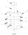
- Fig. 13 The situation where one primary cylinder and one second cylinder may be unloaded simultaneously is illustrated with Fig. 13 .
- the second primary cylinder 2 and the secondary cylinder 3 in Fig. 10 are unloadable cylinders.
- the flow direction of a refrigerant is shown as the direction of an arrow in Fig. 10 .
- the compressor sucks a refrigerant of which the pressure is Ps from the liquid separator through the first air entry and the second air entry, compresses the refrigerant by means of the first primary cylinder 1 and the second primary cylinder 2 and then discharges the refrigerant into the intermediate cavity 8.
- the mixed refrigerant After the refrigerant discharged from the first primary cylinder 1 and the second primary cylinder 2 is mixed with a refrigerant sucked from the flash evaporator through the air supply enthalpy-enhanced opening in the intermediate cavity 8, the mixed refrigerant enters the secondary cylinder 3, is compressed by the secondary cylinder 3, is discharged from the air outlet, and then enters the closed cavity, thus realizing three-cylinder double-stage enthalpy-enhanced operation. In this case, a ratio of a secondary volume to a primary volume may reach 0.3-0.6.
- the compressor sucks a refrigerant of which the pressure is Ps from the liquid separator through the first air entry 11, and compresses the refrigerant by means of the first primary cylinder 1 to form a Pd refrigerant.
- the refrigerant is discharged into the intermediate cavity 8.
- the mixed refrigerant After the refrigerant discharged from the first primary cylinder 1 is mixed with a refrigerant sucked from the flash evaporator through the air supply enthalpy-enhanced opening in the intermediate cavity 8, the mixed refrigerant enters the secondary cylinder 3, and is compressed by the secondary cylinder 3 to form the Pd refrigerant, and the refrigerant is discharged from the air outlet and enters the closed cavity, thus realizing double-cylinder double-stage enthalpy-enhanced operation.
- a ratio of a secondary volume to a primary volume may reach 0.8-1.3.
- the compressor sucks a refrigerant of which the pressure is Ps from the liquid separator through the first air entry and the second air entry, and compresses the refrigerant by means of the first primary cylinder 1 and the second primary cylinder 2, and then discharges the refrigerant into the intermediate cavity 8.
- the refrigerant passes through the secondary cylinder 3, is discharged from the air outlet and then enters the closed cavity, thus realizing double-cylinder operation.
- the compressor sucks a refrigerant of which the pressure is Ps from the liquid separator through the first air entry, the refrigerant is compressed by means of the first primary cylinder and discharged into the intermediate cavity 8, and the refrigerant passes through the secondary cylinder 3, is discharged from the air outlet and enters the closed cavity, thus realizing single-cylinder operation.
- the invention also relates to an air conditioner, which comprises the compressor in any one of the technical solutions. Except the compressor, other components of the air conditioner are components in the conventional art, which will not be elaborated herein one by one.
- the compressor may operate in multiple modes, and different modes may be selected according to different application occasions, thus improving the heating capability, and improving the capabilities of a rated point and an intermediate point.
- the structural limitation is avoided, and the displacement is increased, thus reducing the size of the compressor, and lowering the cost.
- Two primary cylinders may not be limited by series, so as to achieve large-displacement compression.
- the volumes may be variable by changing working and unloading states of the cylinders, and requirements for energy efficiency and capabilities under different compressor working conditions are met.
- the heating capacity under a low-temperature heating situation may be greatly increased by means of three-cylinder double-stage enthalpy-enhanced operation
- the energy efficiency of the intermediate point may be improved by means of single-cylinder operation
- the energy efficiency of the rated point may be improved and guaranteed by means of double-cylinder double-stage enthalpy-enhanced operation or double-cylinder operation.
Landscapes
- Engineering & Computer Science (AREA)
- Mechanical Engineering (AREA)
- General Engineering & Computer Science (AREA)
- Applications Or Details Of Rotary Compressors (AREA)
Description
- The invention relates to the field of refrigeration, and in particular to a multi-cylinder double-stage enthalpy-enhanced and volume-variable compressor and an air conditioner.
- A rolling rotor type double-stage compressor is a double-cylinder double-stage enthalpy-enhanced compressor, generally. Due to limitation of displacement of the compressor, electric auxiliary heating needs to be adopted under low-temperature working conditions to improve the heating capacity of the compressor. If the displacement of the compressor needs to be increased, it is necessary to increase compressor series, thus increasing the size of the compressor, and improving the cost. In addition, the double-cylinder double-stage enthalpy-enhanced compressor cannot operate with high volume ratio under refrigeration working conditions and operate with large displacement and low volume ratio under refrigeration working conditions.
- JPH05106576A discloses a
drive shaft 2, acompressing element 3, middle plates 51,52 and a blade spring, wherein thedrive shaft 2 has a plurality of eccentric parts 2a-2c fitted with respective cylinders 4a-4c, between which middle plates 51, 52 are interposed. The compressingelement 3 is formed by forming these cylinders 4a-4c in a single piece construction wherein they are held pinched by afront head 31 and a rear head 32, and is accommodated in an enclosedcasing 21. The cylinders 4a-4c accommodate rollers 33, with which a plurality of blades 6a-6c slidable in the radial direction are put in slide contact. In this compressor, theblade spring 7 is installed on only one of the blades 6a-6c, for example the one 6b, and at the time of starting, the compressing motion shall be performed only with its corresponding cylinder 4b. -
EP1992820A discloses a freezing device, a compressor 20 is provided with compression mechanisms 61, 62 to have four compression chambers 61, 62, 63, 64 in total. In the compressor 20, the first compression chamber 61 and the second compression chamber 62 differ in the phase of capacity changing cycle from each other by 180° and the third compression chamber 63 and the fourth compression chamber 64 also differ in the phase of capacity changing cycle from each other by 180°. In a cylinder nonoperating mode, refrigerant is compressed in a single stage in each of the first compression chamber 61 and the second compression chamber 62 while the refrigerant compression operation is halted in the third compression chamber 63 and the fourth compression chamber 64. In a two- stage compression mode, refrigerant compressed in a single stage in each of the first compression chamber 61 and the second compression chamber 62 is further compressed in the third compression chamber 63 and the fourth compression chamber 64. - JPS5612085A discloses For the operation of a light load, when a high-pressure solenoid valve 27 is closed and a low-pressure solenoid valve 26 is opened for giving a low- pressure lower than the high-pressure in an
airtight vessel 8 to a diaphragm 23, a stopper 25 of a fixing device 20 is inserted into arecess 21 of a sliding blade 14 of arotary compression element 4, as the total spring constant of the diaphragm 23 and a spring 24 is smaller than the high pressure in theairtight vessel 8. In this construction, the sliding blade 14 is fixed not to be in contact with a roller 12 eccentrically rotating in a cylinder 10 for preventing changes in the capacity of the cylinder 10, and onecompression element 4 inrotary compression elements - In view of the situation in the prior art, the invention is intended to provide a compressor and an air conditioner. The compressor may operate in multiple modes, and different modes may be selected according to different application occasions, thus improving the heating capability, and improving the capabilities of a rated point and an intermediate point. To this end, the technical solutions of the invention are as follows.
- A compressor comprises a first primary cylinder, a second primary cylinder, a secondary cylinder and a lower flange, wherein the first primary cylinder, the second primary cylinder and the secondary cylinder are stacked, a separator is provided between two adjacent cylinders, the secondary cylinder is provided at the same side of the first primary cylinder and the second primary cylinder, or the secondary cylinder is provided between the first primary cylinder and the second primary cylinder, and the lower flange is provided at the lower sides of the first primary cylinder, the second primary cylinder and the secondary cylinder;
the first primary cylinder is provided with a first air entry and a first slide piece groove, a first slide piece is provided in the first slide piece groove, the second primary cylinder is provided with a second air entry and a second slide piece groove, a second slide piece is provided in the second slide piece groove, the secondary cylinder is provided with an air outlet and a third slide piece groove, and a third slide piece is provided in the third slide piece groove; the first primary cylinder and the second primary cylinder are connected in parallel, the first primary cylinder and the second primary cylinder are connected in serial to the secondary cylinder after being connected in parallel, and a refrigerant entering the first air entry and the second air entry is discharged from the air outlet after primary or/and secondary compression; and
two separators are divided into a first separator and a second separator, and any one or two of the first separator, the second separator and a lower flange are provided with a slide piece control device configured to control a slide piece to act, each slide piece control device corresponding to one of the slide pieces. - Preferably, the first primary cylinder and the second primary cylinder are provided at a lower side of the secondary cylinder separately, the first separator or/and the second separator is/are provided with the slide piece control device, and the first primary cylinder or/and the second primary cylinder serve(s) as an unloadable cylinder(s).
- Preferably, the first primary cylinder and the second primary cylinder are provided at a lower side of the secondary cylinder separately, the lower flange is provided with the slide piece control device, and a lower one of the first primary cylinder and the second primary cylinder serves as an unloadable cylinder.
- Furthermore, the first separator or the second separator is provided with the slide piece control device, an upper one of the first primary cylinder and the second primary cylinder serves as an unloadable cylinder, or the secondary cylinder serves as an unloadable cylinder.
- Preferably, the secondary cylinder is provided between the first primary cylinder and the second primary cylinder, the first separator or/and the second separator are provided with the slide piece control device, the first primary cylinder or/and the secondary cylinder serve(s) as an unloadable cylinder(s), or the second primary cylinder or/and the secondary cylinder serve(s) as an unloadable cylinder(s).
- Preferably, the secondary cylinder is provided between the first primary cylinder and the second primary cylinder, the lower flange is provided with the slide piece control device, and a lower one of the first primary cylinder and the second primary cylinder serves as an unloadable cylinder.
- Preferably, the first separator or the second separator is provided with the slide piece control device, an upper one of the first primary cylinder and the second primary cylinder serves as an unloadable cylinder, or the secondary cylinder serves as an unloadable cylinder.
- Preferably, the first primary cylinder and the second primary cylinder are provided at an upper side of the secondary cylinder separately, the first separator or/and the second separator are provided with the slide piece control device, and the first primary cylinder or/and the second primary cylinder serve(s) as an unloadable cylinder(s).
- Preferably, the first primary cylinder and the second primary cylinder are provided at an upper side of the secondary cylinder separately, the lower flange is provided with the slide piece control device, and the secondary cylinder serves as an unloadable cylinder.
- Furthermore, the first separator or the second separator is provided with the slide piece control device, and the first primary cylinder or the second primary cylinder serves as an unloadable cylinder.
- Preferably, the slide piece control device comprises a pin and an elastic reset element, the elastic reset element is provided at a tail of the pin, any one or two of the first slide piece, the second slide piece and the third slide piece are provided with a locking groove, the pin is configured to match with the locking groove, when the pin is provided in the locking groove, the slide piece is locked, and after the pin is disengaged from the locking groove, the slide piece is unlocked.
- Furthermore, the first separator or/and the second separator are provided with a through hole corresponding to the locking groove; or, the first separator or/and the lower flange is/are provided with a through hole corresponding to the locking groove; or, the second separator or/and the lower flange is/are provided with a through hole corresponding to the locking groove; and the pin is provided in the through hole, the pin is in seal fit with the through hole, and the pin can move in an axial direction of the through hole.
- Preferably, a ratio of a secondary volume to a primary volume of the compressor under a double-stage compression mode is 0.3-0.6 or 0.8-1.3.
- Preferably, the lower flange is provided with an intermediate cavity.
- The invention also relates to an air conditioner, which comprises a compressor, the compressor is the compressor in any one of the technical solutions.
- The invention has the beneficial effects as follows.
- In the compressor and air conditioner of the invention, the compressor may operate in multiple modes, and different modes are selected according to different application occasions, thus improving the heating capability, and improving the capabilities of a rated point and an intermediate point. The structural limitation is avoided, and the displacement is increased, thus reducing the size of the compressor, and lowering the cost. Two primary cylinders may not be limited by series, so as to achieve large-displacement compression. The volumes may be variable by changing working and unloading states of the cylinders, and requirements for energy efficiency and capabilities under different compressor working conditions are met. For example, the heating capacity under a low-temperature heating situation may be greatly increased by means of three-cylinder double-stage enthalpy-enhanced operation, the energy efficiency of the intermediate point may be improved by means of single-cylinder operation, and the energy efficiency of the rated point may be improved and guaranteed by means of double-cylinder double-stage enthalpy-enhanced operation or double-cylinder operation.
-
-
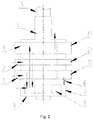
Fig. 1-6 are structural diagrams of a compressor having a volume-variable cylinder according to the invention; -
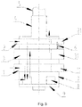
Fig. 7-9 are structural diagrams of a compressor having a secondary cylinder which can be unloaded according to the invention; -
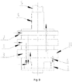
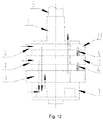
Fig. 10-12 are structural diagrams of a compressor having two primary cylinders which can be unloaded according to the invention; and -
Fig. 13-18 are structural diagrams of a compressor having a primary cylinder and a secondary cylinder which can be unloaded simultaneously according to the invention. - To make the purposes, technical solutions and advantages of the invention clearer, a compressor and air conditioner of the invention will be further illustrated with a three-cylinder rotor compressor in conjunction with the drawings and embodiments in detail. It should be understood that specific embodiments described herein are only intended to explain the invention without limiting the invention.
- Referring to
Fig. 1 to Fig. 18 , an embodiment for a compressor of the invention comprises a firstprimary cylinder 1, a secondprimary cylinder 2, asecondary cylinder 3, alower flange 7, anupper flange 4 and acrankshaft 5, wherein the firstprimary cylinder 1, the secondprimary cylinder 2 and thesecondary cylinder 3 are stacked, a separator is provided between two adjacent cylinders, thesecondary cylinder 3 is provided at the same side of the firstprimary cylinder 1 and the secondprimary cylinder 2, or thesecondary cylinder 3 is provided between the firstprimary cylinder 1 and the secondprimary cylinder 2, thelower flange 7 is provided at the lower sides of the firstprimary cylinder 1, the secondprimary cylinder 2 and thesecondary cylinder 3, thelower flange 7 is provided with anintermediate cavity 8, and alower cover plate 9 is provided at a lower end of thelower flange 7. - The first
primary cylinder 1 is provided with a first air entry and a first slide piece groove (not shown), afirst slide piece 11 is provided in the first slide piece groove, the secondprimary cylinder 2 is provided with a second air entry and a second slide piece groove (not shown), asecond slide piece 21 is provided in the second slide piece groove, thesecondary cylinder 3 is provided with an air outlet and a third slide piece groove (not shown), and athird slide piece 31 is provided in the third slide piece groove; and the firstprimary cylinder 1 and the secondprimary cylinder 2 are connected in parallel, the firstprimary cylinder 1 and the secondprimary cylinder 2 are connected in serial to thesecondary cylinder 3 after being connected in parallel, and a refrigerant entering the first air entry and the second air entry is discharged from the air outlet after primary or/and secondary compression. - The two separators are divided into a first separator and a second separator, and any one or two of the first separator, the second separator and a
lower flange 7 may be provided with a slide piece control device configured to control a slide piece to act, each slidepiece control device 6 corresponding to one of the slide pieces. - As an implementable mode, the slide
piece control device 6 comprises a pin and an elastic reset element, the elastic reset element is provided at a tail of the pin, any one or two of thefirst slide piece 11, thesecond slide piece 21 and thethird slide piece 31 is provided with a locking groove, the pin is configured to match with the locking groove, when the pin is provided in the locking groove, the slide piece is locked, and after the pin is disengaged from the locking groove, the slide piece is unlocked. The elastic reset element may be a spring. - The first separator or/and the second separator is/are provided with a through hole corresponding to the locking groove; or, the first separator or/and the lower flange is/are provided with a through hole corresponding to the locking groove; or, the second separator or/and the lower flange is/are provided with a through hole corresponding to the locking groove; and the pin is provided in the through hole, the pin is in seal fit with the through hole, and the pin can move in an axial direction of the through hole.
- A situation where one of primary cylinders of a three-cylinder double-stage enthalpy-enhanced and volume-variable compressor can be unloaded is as follows.
- As an implementable mode, as shown in
Fig. 1 orFig. 7 , the firstprimary cylinder 1 and the secondprimary cylinder 2 are provided at a lower side of thesecondary cylinder 3 separately, the first separator or the second separator is provided with the slidepiece control device 6, and the firstprimary cylinder 1 or the secondprimary cylinder 2 serves as an unloadable cylinder. - As an implementable mode, as shown in
Fig. 2 , the firstprimary cylinder 1 and the secondprimary cylinder 2 are provided at a lower side of thesecondary cylinder 3 separately, thelower flange 7 is provided with the slidepiece control device 6, and a lower one (firstprimary cylinder 1 inFig. 2 ) of the firstprimary cylinder 1 and the secondprimary cylinder 2 serves as an unloadable cylinder. - As an implementable mode, as shown in
Fig. 3 andFig. 8 , thesecondary cylinder 3 is provided between the firstprimary cylinder 1 and the secondprimary cylinder 2, an upper one of the first separator and the second separator is provided with the slidepiece control device 6, and the secondprimary cylinder 2 serves as an unloadable cylinder. - As an implementable mode, as shown in
Fig. 4 , thesecondary cylinder 3 is provided between the firstprimary cylinder 1 and the secondprimary cylinder 2, thelower flange 7 is provided with the slidepiece control device 6, and a lower one (firstprimary cylinder 1 inFig. 4 ) of the firstprimary cylinder 1 and the secondprimary cylinder 2 serves as an unloadable cylinder. - As an implementable mode, as shown in
Fig. 5 andFig. 6 , the firstprimary cylinder 1 and the secondprimary cylinder 2 are provided at an upper side of thesecondary cylinder 3 separately, the first separator or the second separator is provided with the slidepiece control device 6, and the firstprimary cylinder 1 or the secondprimary cylinder 2 serves as an unloadable cylinder. - The situation where a low-pressure cylinder may be unloaded is illustrated with
Fig. 1 . The secondprimary cylinder 2 inFig. 1 is an unloadable cylinder. When the secondprimary cylinder 2 normally works, the flow direction of a refrigerant is shown as the direction of an arrow inFig. 1 . The compressor sucks a refrigerant of which the pressure is Ps from a liquid separator through the first air entry and the second air entry, compresses the refrigerant and then discharges the refrigerant into theintermediate cavity 8. After the refrigerant discharged from the firstprimary cylinder 1 is mixed with a refrigerant sucked from a flash evaporator through an air supply enthalpy-enhanced opening in theintermediate cavity 8, the mixed refrigerant enters thesecondary cylinder 3, is compressed by thesecondary cylinder 3, is discharged from the air outlet, and then enters a closed cavity, thus realizing three-cylinder double-stage enthalpy-enhanced operation. In this case, a ratio of a secondary volume to a primary volume may reach 0.3-0.6. - When the second
primary cylinder 2 is unloaded and does not work, the compressor sucks a refrigerant of which the pressure is Ps from the liquid separator through the first air entry, performs primary compression on the refrigerant by means of the first primary cylinder and then discharges the refrigerant into theintermediate cavity 8. After the discharged refrigerant is mixed with a refrigerant sucked from the flash evaporator through the air supply enthalpy-enhanced opening in theintermediate cavity 8, the mixed refrigerant enters thesecondary cylinder 3, and is compressed by thesecondary cylinder 3 to form a refrigerant of which the pressure is Pd, and the refrigerant is discharged from the air outlet and enters the closed cavity, thus realizing double-cylinder double-stage enthalpy-enhanced operation. In this case, a ratio of a secondary volume to a primary volume may reach 0.8-1.3. - A situation where a secondary cylinder of a three-cylinder double-stage enthalpy-enhanced and volume-variable compressor can be unloaded is as follows.
- As an implementable mode, as shown in
Fig. 7 , the firstprimary cylinder 1 and the secondprimary cylinder 2 are provided at a lower side of thesecondary cylinder 3 separately, the first separator or the second separator is provided with the slidepiece control device 6, and the firstprimary cylinder 1 or/and the secondprimary cylinder 2 serve(s) as an unloadable cylinder(s). - As an implementable mode, as shown in
Fig. 8 , thesecondary cylinder 3 is provided between the firstprimary cylinder 1 and the secondprimary cylinder 2, a lower one of the first separator and the second separator is provided with the slidepiece control device 6, and thesecondary cylinder 3 serves as an unloadable cylinder. - As an implementable mode, as shown in
Fig. 9 , the firstprimary cylinder 1 and the secondprimary cylinder 2 are provided at an upper side of thesecondary cylinder 3 separately, thelower flange 7 is provided with the slidepiece control device 6, and thesecondary cylinder 3 serves as an unloadable cylinder. - The situation where the
secondary cylinder 3 may be unloaded is illustrated withFig. 7 . Thesecondary cylinder 3 inFig. 7 is an unloadable cylinder. When thesecondary cylinder 3 normally works, the flow direction of a refrigerant is shown as the direction of an arrow inFig. 7 . The compressor sucks a refrigerant of which the pressure is Ps from the liquid separator through the first air entry and the second air entry, performs primary compression on the refrigerant by means of the firstprimary cylinder 1 and the secondprimary cylinder 2, and then discharges the refrigerant into theintermediate cavity 8. After the refrigerant discharged from the firstprimary cylinder 1 and the secondprimary cylinder 2 is mixed with a refrigerant sucked from the flash evaporator through the air supply enthalpy-enhanced opening in theintermediate cavity 8, the mixed refrigerant enters thesecondary cylinder 3, is compressed by thesecondary cylinder 3, is discharged from the air outlet, and then enters the closed cavity, thus realizing three-cylinder double-stage enthalpy-enhanced operation. In this case, a ratio of a secondary volume to a primary volume may reach 0.8-1.3. - When the
secondary cylinder 3 is unloaded and does not work, the compressor sucks a refrigerant of which the pressure is Ps from the liquid separator through the first air entry and the second air entry, and compresses the refrigerant by means of the firstprimary cylinder 1 and the secondprimary cylinder 2 to form a Pd refrigerant. The refrigerant is discharged into theintermediate cavity 8, thesecondary cylinder 3 performs secondary compression, and the refrigerant is discharged from the air outlet and enters the closed cavity, thus realizing double-cylinder operation. - A situation where a first
primary cylinder 1 and secondprimary cylinder 2 of a three-cylinder double-stage enthalpy-enhanced and volume-variable compressor can be unloaded simultaneously is as follows. - As an implementable mode, as shown in
Fig. 10 , the firstprimary cylinder 1 and the secondprimary cylinder 2 are provided at a lower side of thesecondary cylinder 3 separately, thelower flange 7 is provided with the slidepiece control device 6, and a lower one (firstprimary cylinder 1 inFig. 10 ) of the firstprimary cylinder 1 and the secondprimary cylinder 2 serves as an unloadable cylinder; and the first separator (a separator between the firstprimary cylinder 1 and the secondprimary cylinder 2 inFig. 10 ) is also provided with the slidepiece control device 6, and an upper one (secondprimary cylinder 2 inFig. 10 ) of the firstprimary cylinder 1 and the secondprimary cylinder 2 serves as an unloadable cylinder. - As an implementable mode, as shown in
Fig. 11 , thesecondary cylinder 3 is provided between the firstprimary cylinder 1 and the secondprimary cylinder 2, thelower flange 7 is provided with the slidepiece control device 6, and a lower one of the firstprimary cylinder 1 and the secondprimary cylinder 2 serves as an unloadable cylinder; and the second separator (a separator between the secondprimary cylinder 2 and thesecondary cylinder 3 inFig. 11 ) is also provided with the slidepiece control device 6, and an upper one (secondprimary cylinder 2 inFig. 11 ) of the firstprimary cylinder 1 and the secondprimary cylinder 2 also serves as an unloadable cylinder. - As an implementable mode, as shown in
Fig. 12 , the firstprimary cylinder 1 and the secondprimary cylinder 2 are provided at an upper side of thesecondary cylinder 3 separately, the first separator and the second separator are provided with the slidepiece control devices 6, and the firstprimary cylinder 1 and the secondprimary cylinder 2 serve as unloadable cylinders. - The situation where two low-pressure cylinders may be unloaded simultaneously is illustrated with
Fig. 10 . The firstprimary cylinder 1 and the secondprimary cylinder 2 inFig. 10 are unloadable cylinders. When the firstprimary cylinder 1 and the secondprimary cylinder 2 normally work, the flow direction of a refrigerant is shown as the direction of an arrow inFig. 10 . The compressor sucks a refrigerant of which the pressure is Ps from the liquid separator through thefirst air entry 11 and the second air entry, compresses the refrigerant by means of the firstprimary cylinder 1 and the secondprimary cylinder 2 and then discharges the refrigerant into theintermediate cavity 8. After the refrigerant discharged from the firstprimary cylinder 1 and the secondprimary cylinder 2 is mixed with a refrigerant sucked from the flash evaporator through the air supply enthalpy-enhanced opening in theintermediate cavity 8, the mixed refrigerant enters thesecondary cylinder 3, is compressed by thesecondary cylinder 3, is discharged from the air outlet, and then enters the closed cavity, thus realizing three-cylinder double-stage enthalpy-enhanced operation. In this case, a ratio of a secondary volume to a primary volume may reach 0.3-0.6. - When the second
primary cylinder 2 is unloaded and does not work and the firstprimary cylinder 1 normally works, the compressor sucks a refrigerant of which the pressure is Ps from the liquid separator through the first air entry, and compresses the refrigerant by means of the firstprimary cylinder 1 to form a Pd refrigerant. The refrigerant is discharged into theintermediate cavity 8. After the refrigerant discharged from the firstprimary cylinder 1 is mixed with a refrigerant sucked from the flash evaporator through the air supply enthalpy-enhanced opening in theintermediate cavity 8, the mixed refrigerant enters thesecondary cylinder 3, and is compressed by thesecondary cylinder 3 to form the Pd refrigerant, and the refrigerant is discharged from the air outlet and enters the closed cavity, thus realizing double-cylinder double-stage enthalpy-enhanced operation. In this case, a ratio of a secondary volume to a primary volume may reach 0.8-1.3. - When the first
primary cylinder 1 is unloaded and does not work and the secondprimary cylinder 2 normally works, the compressor sucks a refrigerant of which the pressure is Ps from the liquid separator through the second air entry, and compresses the refrigerant by means of the secondprimary cylinder 2 to form a Pd refrigerant. The refrigerant is discharged into theintermediate cavity 8. After the refrigerant discharged from the secondprimary cylinder 2 is mixed with a refrigerant sucked from the flash evaporator through the air supply enthalpy-enhanced opening in theintermediate cavity 8, the mixed refrigerant enters thesecondary cylinder 3, and is compressed by thesecondary cylinder 3 to form the Pd refrigerant, and the refrigerant is discharged from the air outlet and enters the closed cavity, thus realizing double-cylinder double-stage enthalpy-enhanced operation. In this case, a ratio of a secondary volume to a primary volume may reach 0.8-1.3. - When both the first
primary cylinder 1 and the secondprimary cylinder 2 are unloaded and do not work, the compressor sucks a refrigerant of which the pressure is Ps from the liquid separator through the first air entry and the second air entry, the refrigerant passes through the firstprimary cylinder 1, the secondprimary cylinder 2 and theintermediate cavity 8, enters thesecondary cylinder 3, and is compressed by thesecondary cylinder 3 to form a Pd refrigerant, and the refrigerant is discharged from the air outlet and enters the closed cavity, thus realizing single-cylinder operation. - A situation where a primary cylinder and secondary cylinder of a three-cylinder double-stage enthalpy-enhanced and volume-variable compressor can be unloaded simultaneously is as follows.
- As an implementable mode, as shown in
Fig. 13 , the firstprimary cylinder 1 and the secondprimary cylinder 2 are provided at a lower side of thesecondary cylinder 3 separately, the first separator and the second separator are provided with the slidepiece control devices 6, and the firstprimary cylinder 1 or/and the secondprimary cylinder 2 serve(s) as an unloadable cylinder(s). - As an implementable mode, as shown in
Fig. 14 , the firstprimary cylinder 1 and the secondprimary cylinder 2 are provided at the lower side of thesecondary cylinder 3 separately, thelower flange 7 is provided with the slidepiece control device 6, and a lower one (firstprimary cylinder 1 inFig. 14 ) of the firstprimary cylinder 1 and the secondprimary cylinder 2 serves as an unloadable cylinder; and the second separator (a separator between thesecondary cylinder 3 and the secondprimary cylinder 2 inFig. 14 ) is also provided with the slidepiece control device 6, and thesecondary cylinder 3 also serves as an unloadable cylinder. - As an implementable mode, as shown in
Fig. 15 , thesecondary cylinder 3 is provided between the firstprimary cylinder 1 and the secondprimary cylinder 2, thelower flange 7 is provided with the slidepiece control device 6, and a lower one of the firstprimary cylinder 1 and the secondprimary cylinder 2 serves as an unloadable cylinder; and the second separator (a separator between the firstprimary cylinder 1 and thesecondary cylinder 3 inFig. 11 ) is also provided with the slidepiece control device 6, and thesecondary cylinder 3 also serves as an unloadable cylinder. - As an implementable mode, as shown in
Fig. 16 , thesecondary cylinder 3 is provided between the firstprimary cylinder 1 and the secondprimary cylinder 2, the first separator and the second separator are provided with the slidepiece control devices 6 respectively, and both the firstprimary cylinder 1 and the secondprimary cylinder 2 serve as unloadable cylinders. - As an implementable mode, as shown in
Fig. 17 andFig. 18 , the firstprimary cylinder 1 and the secondprimary cylinder 2 are provided at an upper side of thesecondary cylinder 3 respectively, thelower flange 7 is provided with the slidepiece control device 6, and thesecondary cylinder 3 serves as an unloadable cylinder; and the first separator or the second separator is also provided with the slidepiece control device 6, and the firstprimary cylinder 1 or the secondprimary cylinder 2 also serves as an unloadable cylinder. - The situation where one primary cylinder and one second cylinder may be unloaded simultaneously is illustrated with
Fig. 13 . The secondprimary cylinder 2 and thesecondary cylinder 3 inFig. 10 are unloadable cylinders. When the secondprimary cylinder 2 and thesecondary cylinder 3 normally work, the flow direction of a refrigerant is shown as the direction of an arrow inFig. 10 . The compressor sucks a refrigerant of which the pressure is Ps from the liquid separator through the first air entry and the second air entry, compresses the refrigerant by means of the firstprimary cylinder 1 and the secondprimary cylinder 2 and then discharges the refrigerant into theintermediate cavity 8. After the refrigerant discharged from the firstprimary cylinder 1 and the secondprimary cylinder 2 is mixed with a refrigerant sucked from the flash evaporator through the air supply enthalpy-enhanced opening in theintermediate cavity 8, the mixed refrigerant enters thesecondary cylinder 3, is compressed by thesecondary cylinder 3, is discharged from the air outlet, and then enters the closed cavity, thus realizing three-cylinder double-stage enthalpy-enhanced operation. In this case, a ratio of a secondary volume to a primary volume may reach 0.3-0.6. - When the second
primary cylinder 2 is unloaded and does not work and thesecondary cylinder 3 normally works, the compressor sucks a refrigerant of which the pressure is Ps from the liquid separator through thefirst air entry 11, and compresses the refrigerant by means of the firstprimary cylinder 1 to form a Pd refrigerant. The refrigerant is discharged into theintermediate cavity 8. After the refrigerant discharged from the firstprimary cylinder 1 is mixed with a refrigerant sucked from the flash evaporator through the air supply enthalpy-enhanced opening in theintermediate cavity 8, the mixed refrigerant enters thesecondary cylinder 3, and is compressed by thesecondary cylinder 3 to form the Pd refrigerant, and the refrigerant is discharged from the air outlet and enters the closed cavity, thus realizing double-cylinder double-stage enthalpy-enhanced operation. In this case, a ratio of a secondary volume to a primary volume may reach 0.8-1.3. - When the
secondary cylinder 3 is unloaded and does not work and the secondprimary cylinder 2 normally works, the compressor sucks a refrigerant of which the pressure is Ps from the liquid separator through the first air entry and the second air entry, and compresses the refrigerant by means of the firstprimary cylinder 1 and the secondprimary cylinder 2, and then discharges the refrigerant into theintermediate cavity 8. The refrigerant passes through thesecondary cylinder 3, is discharged from the air outlet and then enters the closed cavity, thus realizing double-cylinder operation. - When both the second
primary cylinder 2 and thesecondary cylinder 3 are unloaded and do not work, the compressor sucks a refrigerant of which the pressure is Ps from the liquid separator through the first air entry, the refrigerant is compressed by means of the first primary cylinder and discharged into theintermediate cavity 8, and the refrigerant passes through thesecondary cylinder 3, is discharged from the air outlet and enters the closed cavity, thus realizing single-cylinder operation. - The invention also relates to an air conditioner, which comprises the compressor in any one of the technical solutions. Except the compressor, other components of the air conditioner are components in the conventional art, which will not be elaborated herein one by one.
- In the compressor and air conditioner of the above embodiments, the compressor may operate in multiple modes, and different modes may be selected according to different application occasions, thus improving the heating capability, and improving the capabilities of a rated point and an intermediate point. The structural limitation is avoided, and the displacement is increased, thus reducing the size of the compressor, and lowering the cost. Two primary cylinders may not be limited by series, so as to achieve large-displacement compression. The volumes may be variable by changing working and unloading states of the cylinders, and requirements for energy efficiency and capabilities under different compressor working conditions are met. For example, the heating capacity under a low-temperature heating situation may be greatly increased by means of three-cylinder double-stage enthalpy-enhanced operation, the energy efficiency of the intermediate point may be improved by means of single-cylinder operation, and the energy efficiency of the rated point may be improved and guaranteed by means of double-cylinder double-stage enthalpy-enhanced operation or double-cylinder operation.
- The above embodiments only express several implementations of the invention, and descriptions thereof are relatively specific and detailed, but cannot be accordingly understood as limitation to the scope of the invention. It should be pointed out that those skilled in the art can also make some transformations and improvements without departing from the concept of the invention. These transformations and improvements should fall within the protective scope of the invention. Therefore, the protective scope of the invention should refer to the appended claims.
Claims (15)
- A compressor, comprising:a first primary cylinder (1), a second primary cylinder (2), a secondary cylinder (3) and a lower flange (7), wherein the first primary cylinder (1), the second primary cylinder (2) and the secondary cylinder (3) are stacked, a separator is provided between two adjacent cylinders, the secondary cylinder (3) is provided at the same side of the first primary cylinder (1) and the second primary cylinder (2), or the secondary cylinder (3) is provided between the first primary cylinder (1) and the second primary cylinder (2), and the lower flange (7) is provided at the lower sides of the first primary cylinder (1), the second primary cylinder (2) and the secondary cylinder (3);the first primary cylinder (1) is provided with a first air entry and a first slide piece groove, a first slide piece is provided in the first slide piece groove, the second primary cylinder (2) is provided with a second air entry and a second slide piece groove, a second slide piece is provided in the second slide piece groove, the secondary cylinder (3) is provided with an air outlet and a third slide piece groove, and a third slide piece is provided in the third slide piece groove; characterized in that the first primary cylinder (1) and the second primary cylinder (2) are connected in parallel, the first primary cylinder (1) and the second primary cylinder (2) are connected in serial to the secondary cylinder (3) after being connected in parallel, and a refrigerant entering the first air entry and the second air entry is discharged from the air outlet after primary or/and secondary compression; andtwo separators are divided into a first separator and a second separator, and any one or two of the first separator, the second separator and the lower flange (7) are provided with a slide piece control device (6) configured to control a slide piece to act, each slide piece control device (6) corresponding to one of the slide pieces; wherein during a operation of the compressor, one or two of the first primary cylinder (1), the second primary cylinder (2) and the secondary cylinder (3) has a working state and an unloading state.
- The compressor according to claim 1, wherein
the first primary cylinder (1) and the second primary cylinder (2) are provided at a lower side of the secondary cylinder (3) separately, the first separator or/and the second separator is/are provided with the slide piece control device (6), and the first primary cylinder (1) or/and the second primary cylinder (2) serve(s) as an unloadable cylinder(s). - The compressor according to claim 1, wherein
the first primary cylinder (1) and the second primary cylinder (2) are provided at a lower side of the secondary cylinder (3) separately, the lower flange (7) is provided with the slide piece control device (6), and a lower one of the first primary cylinder (1) and the second primary cylinder (2) serves as an unloadable cylinder. - The compressor according to claim 3, wherein
the first separator or the second separator is provided with the slide piece control device (6), an upper one of the first primary cylinder (1) and the second primary cylinder (2) serves as an unloadable cylinder, or the secondary cylinder (3) serves as an unloadable cylinder. - The compressor according to claim 1, wherein
the secondary cylinder (3) is provided between the first primary cylinder (1) and the second primary cylinder (2), the first separator or/and the second separator are provided with the slide piece control device (6), the first primary cylinder (1) or/and the secondary cylinder (3) serve(s) as an unloadable cylinder(s), or the second primary cylinder (2) or/and the secondary cylinder (3) serve(s) as an unloadable cylinder(s). - The compressor according to claim 1, wherein
the secondary cylinder (3) is provided between the first primary cylinder (1) and the second primary cylinder (2), the lower flange (7) is provided with the slide piece control device (6), and a lower one of the first primary cylinder (1) and the second primary cylinder (2) serves as an unloadable cylinder. - The compressor according to claim 6, wherein
the first separator or the second separator is provided with the slide piece control device (6), an upper one of the first primary cylinder (1) and the second primary cylinder (2) serves as an unloadable cylinder, or the secondary cylinder (3) serves as an unloadable cylinder. - The compressor according to claim 1, wherein
the first primary cylinder (1) and the second primary cylinder (2) are provided at an upper side of the secondary cylinder (3) separately, the first separator or/and the second separator are provided with the slide piece control device (6), and the first primary cylinder (1) or/and the second primary cylinder (2) serve(s) as an unloadable cylinder(s). - The compressor according to claim 1, wherein
the first primary cylinder (1) and the second primary cylinder (2) are provided at an upper side of the secondary cylinder (3) separately, the lower flange (7) is provided with the slide piece control device (6), and the secondary cylinder (3) serves as an unloadable cylinder. - The compressor according to claim 9, wherein
the first separator or the second separator is provided with the slide piece control device (6), and the first primary cylinder (1) or the second primary cylinder (2) serves as an unloadable cylinder. - The compressor according to any one of claims 1 to 10, wherein
the slide piece control device (6) comprises a pin and an elastic reset element, the elastic reset element is provided at a tail of the pin, any one or two of the first slide piece, the second slide piece and the third slide piece are provided with a locking groove, the pin is configured to match with the locking groove, when the pin is provided in the locking groove, the slide piece is locked, and after the pin is disengaged from the locking groove, the slide piece is unlocked. - The compressor according to claim 11, wherein
the first separator or/and the second separator are provided with a through hole corresponding to the locking groove; or, the first separator or/and the lower flange (7) is/are provided with a through hole corresponding to the locking groove; or, the second separator or/and the lower flange (7) is/are provided with a through hole corresponding to the locking groove; and the pin is provided in the through hole, the pin is in seal fit with the through hole, and the pin can move in an axial direction of the through hole. - The compressor according to any one of claims 1 to 10, wherein
a ratio of a secondary volume to a primary volume of the compressor under a double-stage compression mode is 0.3-0.6 or 0.8-1.3. - The compressor according to any one of claims 1 to 10, wherein
the lower flange (7) is provided with an intermediate cavity. - An air conditioner, comprising a compressor, wherein
the compressor is the compressor according to any one of claims 1 to 14.
Applications Claiming Priority (2)
| Application Number | Priority Date | Filing Date | Title |
|---|---|---|---|
| CN201410144072.3A CN103953545B (en) | 2014-04-10 | 2014-04-10 | Compressor and air conditioner |
| PCT/CN2015/078115 WO2015154726A1 (en) | 2014-04-10 | 2015-04-30 | Compressor and air conditioner |
Publications (3)
| Publication Number | Publication Date |
|---|---|
| EP3130807A1 EP3130807A1 (en) | 2017-02-15 |
| EP3130807A4 EP3130807A4 (en) | 2018-03-28 |
| EP3130807B1 true EP3130807B1 (en) | 2019-03-06 |
Family
ID=51330864
Family Applications (1)
| Application Number | Title | Priority Date | Filing Date |
|---|---|---|---|
| EP15777249.2A Active EP3130807B1 (en) | 2014-04-10 | 2015-04-30 | Compressor and air conditioner |
Country Status (6)
| Country | Link |
|---|---|
| US (1) | US10465685B2 (en) |
| EP (1) | EP3130807B1 (en) |
| JP (1) | JP6246977B2 (en) |
| KR (1) | KR20170020742A (en) |
| CN (1) | CN103953545B (en) |
| WO (1) | WO2015154726A1 (en) |
Families Citing this family (19)
| Publication number | Priority date | Publication date | Assignee | Title |
|---|---|---|---|---|
| CN103953545B (en) | 2014-04-10 | 2016-01-27 | 珠海格力节能环保制冷技术研究中心有限公司 | Compressor and air conditioner |
| CN105626523B (en) * | 2014-11-05 | 2018-02-02 | 珠海格力节能环保制冷技术研究中心有限公司 | Compressor, air-conditioning system and compressor control method |
| CN105987657B (en) | 2015-02-12 | 2018-12-07 | 珠海格力电器股份有限公司 | Eddy current sensor for rotating shaft and rotating shaft device |
| CN106704189A (en) * | 2015-08-10 | 2017-05-24 | 珠海格力节能环保制冷技术研究中心有限公司 | Compressor and heat exchange system |
| CN105201838A (en) * | 2015-10-28 | 2015-12-30 | 珠海格力节能环保制冷技术研究中心有限公司 | Rotor compressor |
| CN105298840B (en) * | 2015-11-23 | 2017-07-11 | 珠海格力节能环保制冷技术研究中心有限公司 | Multi-cylinder Dual-level enthalpy adding compressor and air-conditioner, Teat pump boiler and control method |
| CN105736377A (en) * | 2016-04-11 | 2016-07-06 | 珠海格力节能环保制冷技术研究中心有限公司 | Compressor structure |
| CN107956687B (en) * | 2017-10-10 | 2024-01-26 | 珠海凌达压缩机有限公司 | Compressor, operation control method thereof and air conditioner |
| CN108506213A (en) * | 2018-05-25 | 2018-09-07 | 珠海格力节能环保制冷技术研究中心有限公司 | Compressor and air-conditioning system |
| CN110630503B (en) * | 2018-06-25 | 2024-06-28 | 上海海立电器有限公司 | Compressor and exhaust structure and exhaust method thereof |
| CN109026697A (en) * | 2018-08-03 | 2018-12-18 | 天津商业大学 | The compressor with rolling rotor of three cylinder twin-stage sliding slots parallel arrangement |
| CN109026692B (en) * | 2018-08-27 | 2024-05-14 | 珠海凌达压缩机有限公司 | Multi-cylinder pump body structure and compressor |
| CN109113996B (en) * | 2018-10-12 | 2023-03-10 | 珠海凌达压缩机有限公司 | Rotary compressor, refrigerating system and air conditioner with same |
| CN109113994A (en) * | 2018-10-29 | 2019-01-01 | 珠海格力节能环保制冷技术研究中心有限公司 | Pump assembly, positive displacement compressor, air handling system |
| CN109519379B (en) * | 2018-12-12 | 2024-10-01 | 珠海凌达压缩机有限公司 | Compressor and electric appliance comprising same |
| CN109958625B (en) * | 2018-12-20 | 2020-01-07 | 珠海格力电器股份有限公司 | Deformation control method and system for elastic part of pin and variable-capacity compressor |
| CN110159532B (en) * | 2019-06-21 | 2024-10-18 | 珠海格力节能环保制冷技术研究中心有限公司 | Compressor and air conditioner |
| CN113982926A (en) * | 2021-10-19 | 2022-01-28 | 珠海格力节能环保制冷技术研究中心有限公司 | Single-stage and double-stage switching compressor, air conditioning system and control method |
| CN115750353B (en) * | 2022-11-19 | 2023-07-28 | 上海阿波罗机械股份有限公司 | Shielding multistage self-cooling compressor |
Family Cites Families (21)
| Publication number | Priority date | Publication date | Assignee | Title |
|---|---|---|---|---|
| US2957426A (en) * | 1956-12-17 | 1960-10-25 | Ralph C Miller | Series-parallel pump |
| JPS516576A (en) | 1974-07-05 | 1976-01-20 | Citizen Watch Co Ltd | KEITAIDOKEI |
| JPS5190792A (en) | 1975-02-08 | 1976-08-09 | Eaa taorutsukijidokaiheikyabinetsuto | |
| JPS5612085A (en) * | 1979-07-12 | 1981-02-05 | Sanyo Electric Co Ltd | Capacity controller for multicylinder rotary compressor |
| JPS5910792A (en) * | 1982-07-09 | 1984-01-20 | Hitachi Ltd | Rotary compressor |
| JPS5928694U (en) * | 1982-08-17 | 1984-02-22 | 三菱電機株式会社 | Capacity control of multi-cylinder rotary compressor |
| JPH051686A (en) * | 1991-06-27 | 1993-01-08 | Daikin Ind Ltd | Multiple cylinder rotational compressor |
| JPH05106576A (en) * | 1991-08-05 | 1993-04-27 | Daikin Ind Ltd | Multi-cylinder sealed type rotary compressor |
| US5871342A (en) * | 1997-06-09 | 1999-02-16 | Ford Motor Company | Variable capacity rolling piston compressor |
| JP2003328972A (en) * | 2002-05-09 | 2003-11-19 | Hitachi Home & Life Solutions Inc | Hermetic two-cylinder rotary compressor and manufacturing method thereof |
| JP4045154B2 (en) * | 2002-09-11 | 2008-02-13 | 日立アプライアンス株式会社 | Compressor |
| CN100447424C (en) * | 2004-06-15 | 2008-12-31 | 东芝开利株式会社 | Multi-cylinder rotary compressor |
| JP4797715B2 (en) * | 2006-03-09 | 2011-10-19 | ダイキン工業株式会社 | Refrigeration equipment |
| JP5070097B2 (en) * | 2007-08-28 | 2012-11-07 | 東芝キヤリア株式会社 | Two-cylinder rotary compressor and refrigeration cycle apparatus using the same |
| US8985976B2 (en) * | 2008-05-19 | 2015-03-24 | Panasonic Intellectual Property Management Co., Ltd. | Two-stage rotary expander, expander-integrated compressor, and refrigeration cycle apparatus |
| US20140094727A1 (en) * | 2012-09-28 | 2014-04-03 | Covidien Lp | Compression device pumping |
| DE102012112720B4 (en) * | 2012-12-20 | 2017-01-12 | Dr. Ing. H.C. F. Porsche Aktiengesellschaft | pump |
| CN203809296U (en) * | 2014-04-10 | 2014-09-03 | 珠海格力节能环保制冷技术研究中心有限公司 | Compressor and air conditioner |
| CN103953544B (en) * | 2014-04-10 | 2016-01-27 | 珠海格力节能环保制冷技术研究中心有限公司 | Compressor and air conditioner |
| CN103953545B (en) | 2014-04-10 | 2016-01-27 | 珠海格力节能环保制冷技术研究中心有限公司 | Compressor and air conditioner |
| CN103954064B (en) * | 2014-04-15 | 2016-04-13 | 珠海格力电器股份有限公司 | Refrigerating device |
-
2014
- 2014-04-10 CN CN201410144072.3A patent/CN103953545B/en active Active
-
2015
- 2015-04-30 JP JP2017504233A patent/JP6246977B2/en active Active
- 2015-04-30 US US15/303,096 patent/US10465685B2/en active Active
- 2015-04-30 KR KR1020167031402A patent/KR20170020742A/en not_active Ceased
- 2015-04-30 WO PCT/CN2015/078115 patent/WO2015154726A1/en not_active Ceased
- 2015-04-30 EP EP15777249.2A patent/EP3130807B1/en active Active
Non-Patent Citations (1)
| Title |
|---|
| None * |
Also Published As
| Publication number | Publication date |
|---|---|
| JP2017514066A (en) | 2017-06-01 |
| EP3130807A1 (en) | 2017-02-15 |
| US10465685B2 (en) | 2019-11-05 |
| WO2015154726A1 (en) | 2015-10-15 |
| US20170030355A1 (en) | 2017-02-02 |
| JP6246977B2 (en) | 2017-12-13 |
| EP3130807A4 (en) | 2018-03-28 |
| KR20170020742A (en) | 2017-02-24 |
| CN103953545A (en) | 2014-07-30 |
| CN103953545B (en) | 2016-01-27 |
Similar Documents
| Publication | Publication Date | Title |
|---|---|---|
| US10465685B2 (en) | Air conditioner with stacked parallel and serial compressor cylinders | |
| JP6244478B2 (en) | Compressor and air conditioner | |
| CN202851355U (en) | Single-stage and double-stage interchangeable double-cylinder compressor | |
| CN203272136U (en) | Single-cylinder multistage compressor | |
| EP3217013B1 (en) | Compressor, air-conditioning system and compressor control method | |
| CN203248363U (en) | Dual-mode compression pump body and double-cylinder compressor using same | |
| CN103573625B (en) | Rotary compressor with variable volume | |
| CN103727034B (en) | Compressor | |
| CN105065272B (en) | Rotary compressor | |
| EP3392507B1 (en) | Variable-capacity cylinder with sliding vane control structure and variable-capacity compressor | |
| CN103486032A (en) | Two-stage variable capacity compressor and air conditioner | |
| CN111075721B (en) | Pump body subassembly and variable volume compressor | |
| CN203335407U (en) | Single-cylinder two-stage compression pump body and compressor | |
| CN103511266A (en) | Rotary compressor | |
| JP6408698B2 (en) | Rotating compressor and refrigeration cycle apparatus including the same | |
| US20190024658A1 (en) | Rotary compressor | |
| CN106286292B (en) | Compression assembly, varying capacity screw compressor and air conditioner | |
| CN104632627A (en) | Compressor pump body and compressor comprising same | |
| CN203809296U (en) | Compressor and air conditioner | |
| CN204941943U (en) | Rotary compressor | |
| CN203230583U (en) | Rotary compressor | |
| CN203035481U (en) | Multi-stage compressor for improving low-pressure ratio operation efficiency | |
| CN207297358U (en) | Rotary compressor and there is its air-conditioning system | |
| CN106593870A (en) | Rotary compressor and refrigeration system with rotary compressor | |
| CN206299563U (en) | Rotary compressor and the refrigeration system with the rotary compressor |
Legal Events
| Date | Code | Title | Description |
|---|---|---|---|
| STAA | Information on the status of an ep patent application or granted ep patent |
Free format text: STATUS: THE INTERNATIONAL PUBLICATION HAS BEEN MADE |
|
| PUAI | Public reference made under article 153(3) epc to a published international application that has entered the european phase |
Free format text: ORIGINAL CODE: 0009012 |
|
| STAA | Information on the status of an ep patent application or granted ep patent |
Free format text: STATUS: REQUEST FOR EXAMINATION WAS MADE |
|
| 17P | Request for examination filed |
Effective date: 20161018 |
|
| AK | Designated contracting states |
Kind code of ref document: A1 Designated state(s): AL AT BE BG CH CY CZ DE DK EE ES FI FR GB GR HR HU IE IS IT LI LT LU LV MC MK MT NL NO PL PT RO RS SE SI SK SM TR |
|
| AX | Request for extension of the european patent |
Extension state: BA ME |
|
| DAV | Request for validation of the european patent (deleted) | ||
| DAX | Request for extension of the european patent (deleted) | ||
| RIC1 | Information provided on ipc code assigned before grant |
Ipc: F04C 18/356 20060101ALI20180215BHEP Ipc: F04C 23/00 20060101AFI20180215BHEP |
|
| A4 | Supplementary search report drawn up and despatched |
Effective date: 20180223 |
|
| GRAP | Despatch of communication of intention to grant a patent |
Free format text: ORIGINAL CODE: EPIDOSNIGR1 |
|
| STAA | Information on the status of an ep patent application or granted ep patent |
Free format text: STATUS: GRANT OF PATENT IS INTENDED |
|
| INTG | Intention to grant announced |
Effective date: 20181129 |
|
| RAP1 | Party data changed (applicant data changed or rights of an application transferred) |
Owner name: GREEN REFRIGERATION EQUIPMENT ENGINEERING RESEARCH |
|
| GRAS | Grant fee paid |
Free format text: ORIGINAL CODE: EPIDOSNIGR3 |
|
| GRAA | (expected) grant |
Free format text: ORIGINAL CODE: 0009210 |
|
| STAA | Information on the status of an ep patent application or granted ep patent |
Free format text: STATUS: THE PATENT HAS BEEN GRANTED |
|
| AK | Designated contracting states |
Kind code of ref document: B1 Designated state(s): AL AT BE BG CH CY CZ DE DK EE ES FI FR GB GR HR HU IE IS IT LI LT LU LV MC MK MT NL NO PL PT RO RS SE SI SK SM TR |
|
| REG | Reference to a national code |
Ref country code: GB Ref legal event code: FG4D |
|
| REG | Reference to a national code |
Ref country code: CH Ref legal event code: EP Ref country code: AT Ref legal event code: REF Ref document number: 1104914 Country of ref document: AT Kind code of ref document: T Effective date: 20190315 |
|
| REG | Reference to a national code |
Ref country code: DE Ref legal event code: R096 Ref document number: 602015025952 Country of ref document: DE |
|
| REG | Reference to a national code |
Ref country code: IE Ref legal event code: FG4D |
|
| REG | Reference to a national code |
Ref country code: NL Ref legal event code: MP Effective date: 20190306 |
|
| REG | Reference to a national code |
Ref country code: LT Ref legal event code: MG4D |
|
| PG25 | Lapsed in a contracting state [announced via postgrant information from national office to epo] |
Ref country code: LT Free format text: LAPSE BECAUSE OF FAILURE TO SUBMIT A TRANSLATION OF THE DESCRIPTION OR TO PAY THE FEE WITHIN THE PRESCRIBED TIME-LIMIT Effective date: 20190306 Ref country code: NO Free format text: LAPSE BECAUSE OF FAILURE TO SUBMIT A TRANSLATION OF THE DESCRIPTION OR TO PAY THE FEE WITHIN THE PRESCRIBED TIME-LIMIT Effective date: 20190606 Ref country code: SE Free format text: LAPSE BECAUSE OF FAILURE TO SUBMIT A TRANSLATION OF THE DESCRIPTION OR TO PAY THE FEE WITHIN THE PRESCRIBED TIME-LIMIT Effective date: 20190306 Ref country code: FI Free format text: LAPSE BECAUSE OF FAILURE TO SUBMIT A TRANSLATION OF THE DESCRIPTION OR TO PAY THE FEE WITHIN THE PRESCRIBED TIME-LIMIT Effective date: 20190306 |
|
| PG25 | Lapsed in a contracting state [announced via postgrant information from national office to epo] |
Ref country code: HR Free format text: LAPSE BECAUSE OF FAILURE TO SUBMIT A TRANSLATION OF THE DESCRIPTION OR TO PAY THE FEE WITHIN THE PRESCRIBED TIME-LIMIT Effective date: 20190306 Ref country code: GR Free format text: LAPSE BECAUSE OF FAILURE TO SUBMIT A TRANSLATION OF THE DESCRIPTION OR TO PAY THE FEE WITHIN THE PRESCRIBED TIME-LIMIT Effective date: 20190607 Ref country code: BG Free format text: LAPSE BECAUSE OF FAILURE TO SUBMIT A TRANSLATION OF THE DESCRIPTION OR TO PAY THE FEE WITHIN THE PRESCRIBED TIME-LIMIT Effective date: 20190606 Ref country code: RS Free format text: LAPSE BECAUSE OF FAILURE TO SUBMIT A TRANSLATION OF THE DESCRIPTION OR TO PAY THE FEE WITHIN THE PRESCRIBED TIME-LIMIT Effective date: 20190306 Ref country code: LV Free format text: LAPSE BECAUSE OF FAILURE TO SUBMIT A TRANSLATION OF THE DESCRIPTION OR TO PAY THE FEE WITHIN THE PRESCRIBED TIME-LIMIT Effective date: 20190306 Ref country code: NL Free format text: LAPSE BECAUSE OF FAILURE TO SUBMIT A TRANSLATION OF THE DESCRIPTION OR TO PAY THE FEE WITHIN THE PRESCRIBED TIME-LIMIT Effective date: 20190306 |
|
| REG | Reference to a national code |
Ref country code: AT Ref legal event code: MK05 Ref document number: 1104914 Country of ref document: AT Kind code of ref document: T Effective date: 20190306 |
|
| PG25 | Lapsed in a contracting state [announced via postgrant information from national office to epo] |
Ref country code: SK Free format text: LAPSE BECAUSE OF FAILURE TO SUBMIT A TRANSLATION OF THE DESCRIPTION OR TO PAY THE FEE WITHIN THE PRESCRIBED TIME-LIMIT Effective date: 20190306 Ref country code: IT Free format text: LAPSE BECAUSE OF FAILURE TO SUBMIT A TRANSLATION OF THE DESCRIPTION OR TO PAY THE FEE WITHIN THE PRESCRIBED TIME-LIMIT Effective date: 20190306 Ref country code: ES Free format text: LAPSE BECAUSE OF FAILURE TO SUBMIT A TRANSLATION OF THE DESCRIPTION OR TO PAY THE FEE WITHIN THE PRESCRIBED TIME-LIMIT Effective date: 20190306 Ref country code: PT Free format text: LAPSE BECAUSE OF FAILURE TO SUBMIT A TRANSLATION OF THE DESCRIPTION OR TO PAY THE FEE WITHIN THE PRESCRIBED TIME-LIMIT Effective date: 20190706 Ref country code: AL Free format text: LAPSE BECAUSE OF FAILURE TO SUBMIT A TRANSLATION OF THE DESCRIPTION OR TO PAY THE FEE WITHIN THE PRESCRIBED TIME-LIMIT Effective date: 20190306 Ref country code: EE Free format text: LAPSE BECAUSE OF FAILURE TO SUBMIT A TRANSLATION OF THE DESCRIPTION OR TO PAY THE FEE WITHIN THE PRESCRIBED TIME-LIMIT Effective date: 20190306 Ref country code: CZ Free format text: LAPSE BECAUSE OF FAILURE TO SUBMIT A TRANSLATION OF THE DESCRIPTION OR TO PAY THE FEE WITHIN THE PRESCRIBED TIME-LIMIT Effective date: 20190306 Ref country code: RO Free format text: LAPSE BECAUSE OF FAILURE TO SUBMIT A TRANSLATION OF THE DESCRIPTION OR TO PAY THE FEE WITHIN THE PRESCRIBED TIME-LIMIT Effective date: 20190306 |
|
| PG25 | Lapsed in a contracting state [announced via postgrant information from national office to epo] |
Ref country code: PL Free format text: LAPSE BECAUSE OF FAILURE TO SUBMIT A TRANSLATION OF THE DESCRIPTION OR TO PAY THE FEE WITHIN THE PRESCRIBED TIME-LIMIT Effective date: 20190306 Ref country code: SM Free format text: LAPSE BECAUSE OF FAILURE TO SUBMIT A TRANSLATION OF THE DESCRIPTION OR TO PAY THE FEE WITHIN THE PRESCRIBED TIME-LIMIT Effective date: 20190306 |
|
| REG | Reference to a national code |
Ref country code: CH Ref legal event code: PL |
|
| REG | Reference to a national code |
Ref country code: DE Ref legal event code: R097 Ref document number: 602015025952 Country of ref document: DE |
|
| REG | Reference to a national code |
Ref country code: BE Ref legal event code: MM Effective date: 20190430 |
|
| PG25 | Lapsed in a contracting state [announced via postgrant information from national office to epo] |
Ref country code: IS Free format text: LAPSE BECAUSE OF FAILURE TO SUBMIT A TRANSLATION OF THE DESCRIPTION OR TO PAY THE FEE WITHIN THE PRESCRIBED TIME-LIMIT Effective date: 20190706 Ref country code: LU Free format text: LAPSE BECAUSE OF NON-PAYMENT OF DUE FEES Effective date: 20190430 Ref country code: AT Free format text: LAPSE BECAUSE OF FAILURE TO SUBMIT A TRANSLATION OF THE DESCRIPTION OR TO PAY THE FEE WITHIN THE PRESCRIBED TIME-LIMIT Effective date: 20190306 |
|
| PLBE | No opposition filed within time limit |
Free format text: ORIGINAL CODE: 0009261 |
|
| STAA | Information on the status of an ep patent application or granted ep patent |
Free format text: STATUS: NO OPPOSITION FILED WITHIN TIME LIMIT |
|
| PG25 | Lapsed in a contracting state [announced via postgrant information from national office to epo] |
Ref country code: LI Free format text: LAPSE BECAUSE OF NON-PAYMENT OF DUE FEES Effective date: 20190430 Ref country code: CH Free format text: LAPSE BECAUSE OF NON-PAYMENT OF DUE FEES Effective date: 20190430 Ref country code: DK Free format text: LAPSE BECAUSE OF FAILURE TO SUBMIT A TRANSLATION OF THE DESCRIPTION OR TO PAY THE FEE WITHIN THE PRESCRIBED TIME-LIMIT Effective date: 20190306 Ref country code: MC Free format text: LAPSE BECAUSE OF FAILURE TO SUBMIT A TRANSLATION OF THE DESCRIPTION OR TO PAY THE FEE WITHIN THE PRESCRIBED TIME-LIMIT Effective date: 20190306 |
|
| 26N | No opposition filed |
Effective date: 20191209 |
|
| PG25 | Lapsed in a contracting state [announced via postgrant information from national office to epo] |
Ref country code: SI Free format text: LAPSE BECAUSE OF FAILURE TO SUBMIT A TRANSLATION OF THE DESCRIPTION OR TO PAY THE FEE WITHIN THE PRESCRIBED TIME-LIMIT Effective date: 20190306 Ref country code: BE Free format text: LAPSE BECAUSE OF NON-PAYMENT OF DUE FEES Effective date: 20190430 |
|
| PG25 | Lapsed in a contracting state [announced via postgrant information from national office to epo] |
Ref country code: TR Free format text: LAPSE BECAUSE OF FAILURE TO SUBMIT A TRANSLATION OF THE DESCRIPTION OR TO PAY THE FEE WITHIN THE PRESCRIBED TIME-LIMIT Effective date: 20190306 |
|
| PG25 | Lapsed in a contracting state [announced via postgrant information from national office to epo] |
Ref country code: IE Free format text: LAPSE BECAUSE OF NON-PAYMENT OF DUE FEES Effective date: 20190430 |
|
| PG25 | Lapsed in a contracting state [announced via postgrant information from national office to epo] |
Ref country code: CY Free format text: LAPSE BECAUSE OF FAILURE TO SUBMIT A TRANSLATION OF THE DESCRIPTION OR TO PAY THE FEE WITHIN THE PRESCRIBED TIME-LIMIT Effective date: 20190306 |
|
| PG25 | Lapsed in a contracting state [announced via postgrant information from national office to epo] |
Ref country code: HU Free format text: LAPSE BECAUSE OF FAILURE TO SUBMIT A TRANSLATION OF THE DESCRIPTION OR TO PAY THE FEE WITHIN THE PRESCRIBED TIME-LIMIT; INVALID AB INITIO Effective date: 20150430 Ref country code: MT Free format text: LAPSE BECAUSE OF FAILURE TO SUBMIT A TRANSLATION OF THE DESCRIPTION OR TO PAY THE FEE WITHIN THE PRESCRIBED TIME-LIMIT Effective date: 20190306 |
|
| PG25 | Lapsed in a contracting state [announced via postgrant information from national office to epo] |
Ref country code: MK Free format text: LAPSE BECAUSE OF FAILURE TO SUBMIT A TRANSLATION OF THE DESCRIPTION OR TO PAY THE FEE WITHIN THE PRESCRIBED TIME-LIMIT Effective date: 20190306 |
|
| P01 | Opt-out of the competence of the unified patent court (upc) registered |
Effective date: 20230530 |
|
| PGFP | Annual fee paid to national office [announced via postgrant information from national office to epo] |
Ref country code: DE Payment date: 20250417 Year of fee payment: 11 |
|
| PGFP | Annual fee paid to national office [announced via postgrant information from national office to epo] |
Ref country code: GB Payment date: 20260323 Year of fee payment: 12 |
|
| PGFP | Annual fee paid to national office [announced via postgrant information from national office to epo] |
Ref country code: FR Payment date: 20260317 Year of fee payment: 12 |