EP3130772B1 - Pressuring system for a vehicle engine components for water protection - Google Patents
Pressuring system for a vehicle engine components for water protection Download PDFInfo
- Publication number
- EP3130772B1 EP3130772B1 EP16183100.3A EP16183100A EP3130772B1 EP 3130772 B1 EP3130772 B1 EP 3130772B1 EP 16183100 A EP16183100 A EP 16183100A EP 3130772 B1 EP3130772 B1 EP 3130772B1
- Authority
- EP
- European Patent Office
- Prior art keywords
- vehicle engine
- timing belt
- control valve
- starter motor
- gases
- Prior art date
- Legal status (The legal status is an assumption and is not a legal conclusion. Google has not performed a legal analysis and makes no representation as to the accuracy of the status listed.)
- Active
Links
Images







Classifications
-
- F—MECHANICAL ENGINEERING; LIGHTING; HEATING; WEAPONS; BLASTING
- F02—COMBUSTION ENGINES; HOT-GAS OR COMBUSTION-PRODUCT ENGINE PLANTS
- F02D—CONTROLLING COMBUSTION ENGINES
- F02D41/00—Electrical control of supply of combustible mixture or its constituents
- F02D41/0002—Controlling intake air
-
- F—MECHANICAL ENGINEERING; LIGHTING; HEATING; WEAPONS; BLASTING
- F02—COMBUSTION ENGINES; HOT-GAS OR COMBUSTION-PRODUCT ENGINE PLANTS
- F02N—STARTING OF COMBUSTION ENGINES; STARTING AIDS FOR SUCH ENGINES, NOT OTHERWISE PROVIDED FOR
- F02N9/00—Starting of engines by supplying auxiliary pressure fluid to their working chambers
- F02N9/04—Starting of engines by supplying auxiliary pressure fluid to their working chambers the pressure fluid being generated otherwise, e.g. by compressing air
-
- F—MECHANICAL ENGINEERING; LIGHTING; HEATING; WEAPONS; BLASTING
- F01—MACHINES OR ENGINES IN GENERAL; ENGINE PLANTS IN GENERAL; STEAM ENGINES
- F01M—LUBRICATING OF MACHINES OR ENGINES IN GENERAL; LUBRICATING INTERNAL COMBUSTION ENGINES; CRANKCASE VENTILATING
- F01M13/00—Crankcase ventilating or breathing
- F01M13/06—Crankcase ventilating or breathing specially adapted for submersible engines, e.g. of armoured vehicles
-
- B—PERFORMING OPERATIONS; TRANSPORTING
- B60—VEHICLES IN GENERAL
- B60F—VEHICLES FOR USE BOTH ON RAIL AND ON ROAD; VEHICLES CAPABLE OF TRAVELLING IN OR ON DIFFERENT MEDIA, e.g. AMPHIBIOUS VEHICLES
- B60F3/00—Amphibious vehicles, i.e. vehicles capable of travelling both on land and on water; Land vehicles capable of travelling under water
- B60F3/003—Parts or details of the vehicle structure; vehicle arrangements not otherwise provided for
- B60F3/0053—Particular devices for gas circulation, e.g. air admission, cooling, watertightness
-
- F—MECHANICAL ENGINEERING; LIGHTING; HEATING; WEAPONS; BLASTING
- F02—COMBUSTION ENGINES; HOT-GAS OR COMBUSTION-PRODUCT ENGINE PLANTS
- F02B—INTERNAL-COMBUSTION PISTON ENGINES; COMBUSTION ENGINES IN GENERAL
- F02B77/00—Component parts, details or accessories, not otherwise provided for
- F02B77/08—Safety, indicating, or supervising devices
-
- F—MECHANICAL ENGINEERING; LIGHTING; HEATING; WEAPONS; BLASTING
- F02—COMBUSTION ENGINES; HOT-GAS OR COMBUSTION-PRODUCT ENGINE PLANTS
- F02M—SUPPLYING COMBUSTION ENGINES IN GENERAL WITH COMBUSTIBLE MIXTURES OR CONSTITUENTS THEREOF
- F02M35/00—Combustion-air cleaners, air intakes, intake silencers, or induction systems specially adapted for, or arranged on, internal-combustion engines
- F02M35/10—Air intakes; Induction systems
- F02M35/10006—Air intakes; Induction systems characterised by the position of elements of the air intake system in direction of the air intake flow, i.e. between ambient air inlet and supply to the combustion chamber
- F02M35/10019—Means upstream of the fuel injection system, carburettor or plenum chamber
-
- F—MECHANICAL ENGINEERING; LIGHTING; HEATING; WEAPONS; BLASTING
- F02—COMBUSTION ENGINES; HOT-GAS OR COMBUSTION-PRODUCT ENGINE PLANTS
- F02M—SUPPLYING COMBUSTION ENGINES IN GENERAL WITH COMBUSTIBLE MIXTURES OR CONSTITUENTS THEREOF
- F02M35/00—Combustion-air cleaners, air intakes, intake silencers, or induction systems specially adapted for, or arranged on, internal-combustion engines
- F02M35/10—Air intakes; Induction systems
- F02M35/10006—Air intakes; Induction systems characterised by the position of elements of the air intake system in direction of the air intake flow, i.e. between ambient air inlet and supply to the combustion chamber
- F02M35/10078—Connections of intake systems to the engine
-
- F—MECHANICAL ENGINEERING; LIGHTING; HEATING; WEAPONS; BLASTING
- F02—COMBUSTION ENGINES; HOT-GAS OR COMBUSTION-PRODUCT ENGINE PLANTS
- F02M—SUPPLYING COMBUSTION ENGINES IN GENERAL WITH COMBUSTIBLE MIXTURES OR CONSTITUENTS THEREOF
- F02M35/00—Combustion-air cleaners, air intakes, intake silencers, or induction systems specially adapted for, or arranged on, internal-combustion engines
- F02M35/10—Air intakes; Induction systems
- F02M35/10242—Devices or means connected to or integrated into air intakes; Air intakes combined with other engine or vehicle parts
- F02M35/10275—Means to avoid a change in direction of incoming fluid, e.g. all intake ducts diverging from plenum chamber at acute angles; Check valves; Flame arrestors for backfire prevention
-
- F—MECHANICAL ENGINEERING; LIGHTING; HEATING; WEAPONS; BLASTING
- F02—COMBUSTION ENGINES; HOT-GAS OR COMBUSTION-PRODUCT ENGINE PLANTS
- F02M—SUPPLYING COMBUSTION ENGINES IN GENERAL WITH COMBUSTIBLE MIXTURES OR CONSTITUENTS THEREOF
- F02M35/00—Combustion-air cleaners, air intakes, intake silencers, or induction systems specially adapted for, or arranged on, internal-combustion engines
- F02M35/10—Air intakes; Induction systems
- F02M35/10373—Sensors for intake systems
-
- F—MECHANICAL ENGINEERING; LIGHTING; HEATING; WEAPONS; BLASTING
- F02—COMBUSTION ENGINES; HOT-GAS OR COMBUSTION-PRODUCT ENGINE PLANTS
- F02M—SUPPLYING COMBUSTION ENGINES IN GENERAL WITH COMBUSTIBLE MIXTURES OR CONSTITUENTS THEREOF
- F02M35/00—Combustion-air cleaners, air intakes, intake silencers, or induction systems specially adapted for, or arranged on, internal-combustion engines
- F02M35/10—Air intakes; Induction systems
- F02M35/104—Intake manifolds
Definitions
- the present disclosure relates to a system for pressuring a belt cover of a vehicle engine.
- the pressuring system may also be used to pressure a starter motor of a vehicle engine.
- Timing belt components used on vehicles are not designed to be operated in a submerged condition underwater. Starter motor components, while sealed, are also not designed to be operated in a submerged condition underwater.
- the US patent US3477413 describes another system for building up pressure within a crankcase of a submersed internal combustion engine, which includes a pump for supplying pressurized external air directly into the crankcase via a dedicated intake pipe.
- the French patent application FR918023 teaches to build up the pressure within the crankcase of an internal combustion engine by diverting part of the exhaust gases produced by the engine from the exhaust pipe into the crankcase.
- An engine 20 for a vehicle 22 which has a pressuring system 24 for pressuring a cavity 26 formed by a timing belt cover 28, and may be used to pressurize a cavity 30 formed as part of the starter motor 32 to minimize or prevent water and/or debris entry into the cavities 26, 30 when the vehicle 22 is submerged, to prevent water, for example rainwater, and/or debris entry when the vehicle 22 is running on land, or dust/debris entry into the cavities 26, 30 when the vehicle 22 is running with heavy dust.
- the pressuring system 24 introduces gases under pressure into the cavities 26, 30 to minimize or prevent the ingress of water/dust/debris into the cavities 26, 30, thereby protecting the components within the cavities 26, 30.
- the engine 20 has an engine block 34 which include the customary components for enabling operation of the vehicle 22.
- the specific components which relate to the pressuring system 24 are specifically discussed herein.
- gases flows from atmosphere through an intake system 36 to the engine block 34. Waste gases travel from the engine block 34 to an outlet 37.
- the intake system 36 includes an air filter 38 which receives gases from the atmosphere, an air hose 39 between the air filter 38 and a turbocompressor inlet, a turbocompressor 40 which receives the gases from the turbocompressor inlet and compresses the gases, an air hose 41 between the turbocompressor 40 and an air cooler inlet, an air cooler 42 which receives the compressed gases from the air cooler inlet to cool the compressed gases generated by the turbocompressor 40, an air hose 43 between the air cooler 42 and an intake manifold inlet, and an intake manifold 44 which receives the cooled gases from the air cooler 42.
- the cooled compressed gases flow through the intake manifold 44 and into the engine block 34 for use by the engine 20 in a typical manner.
- the pressure of the gases in the intake manifold 44 is greater than ambient.
- the timing belt cover 28 is attached to the engine block 34 in a customary manner.
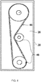
- a timing belt 46 which is used in operating the engine 20 in a known manner, is mounted within the cavity 26.
- the timing belt 46 is driven in a conventional manner and includes operating components 48, such as crank shafts, sprockets, pulleys, bearings, oil seals, etc., which are mounted within the cavity 26 and interact with the components in the engine block 34.
- the timing belt cover 28 is not completely sealed to the engine block 34.
- the timing belt 46 and its components 48 are not designed to operate in a submerged situation.
- the starter motor 32 is attached to the engine block 34 in a customary manner.
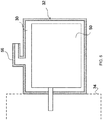
- the components 50 of the starter motor 32 are mounted within the cavity 30 which is formed by a starter motor cover 52.
- Starter motors 32 are normally protected against water intrusion, but the starter motor cover 52 is not completely sealed against water intrusion.
- a starter motor 32 is not designed to operate in a submerged situation.
- the pressuring system 24 includes a gases pipe 54 which extends between the intake manifold 44 and the timing belt cover 28 for feeding pressurized gases from the intake manifold 44 to the timing belt cavity 26.
- the gases pipe 54 is sealed to the intake manifold 44 and to the timing belt cover 28 and suitable connectors (not shown) may be provided to effect these connections.
- the pressuring system 24 may also include a gases pipe 56 which extends between the intake manifold 44 and the starter motor cover 52 for feeding pressurized gases from the intake manifold 44 to the cavity 30 formed within the starter motor 32.
- the gases pipe 56 is sealed to the intake manifold 44 and to the starter motor cover 52 and suitable connectors (not shown) may be provided to effect these connections.
- the gases pipes 54, 56 may be formed with a Y-shape such that a single gases pipe extends from the intake manifold 44, a first branch of the gases pipe extends to the timing belt cover 28, and a second branch extends to the starter motor cover 52.
- the gases pipe 54, 56 and branches are sealed to the intake manifold 44, the timing belt cover 28 and the starter motor cover 52 and suitable connectors (not shown) may be provided to effect these connections. Therefore, pressurized gases flows from the intake manifold 44 to pressurize both the cavities 26, 30.
- the first gases pipe 54 extends from the intake manifold 44 to the timing belt cover 28, and the second gases pipe 56 extends from the timing belt cover 28 to the starter motor cover 52.
- the gases pipe 54 is sealed to the intake manifold 44 and to the timing belt cover 28 and suitable connectors (not shown) may be provided to effect these connections.
- the gases pipe 56 is sealed to the intake manifold 44 and to the starter motor cover 52 and suitable connectors (not shown) may be provided to effect these connections. Therefore, pressurized gases flows from the intake manifold 44 to pressurize both the cavities 26, 30.
- the pressuring system 24 is a closed-loop feedback system and/or method.
- the pressuring system 24 includes a control valve 58 and a pressure sensor 60, both of which are in communication with an electronic control module (ECM) 62.
- ECM electronic control module
- the control valve 58 is mounted on the intake manifold 44.
- the control valve 58 may be mounted on the gases pipe 54.
- the pressure sensor 60 may be mounted along the gases pipe 54, in the timing belt cover 28, and/or in the intake manifold 44. If pressurization is provided to the starter motor 32, a pressure sensor 64, see FIGS.
- the pressure sensor 64 is not required.
- the pressure sensor(s) 60, 64 measures the gases pressure and sends information to the ECM 62.
- the ECM 62 processes the information and is configured to control the opening and the closing of the control valve 58 to appropriately supply gases to the cavity(ies) 26, 30 as necessary for the required amount of pressurization.
- the control valve 58 is eliminated and the pressuring system 24 includes a pressure relief valve 66 mounted on the timing belt cover 28. Gases are always supplied to the timing belt cover 28 via gases pipe 54. The pressure relief valve 66 opens when the pressure exceeds a predetermined pressure; this minimizes the impact on the oil seals in the timing belt 46 which can operate with limited positive pressure. If pressurization is provided to the starter motor 32 via gases pipe 56 as shown in FIGS. 11 and 12 , a pressure relief valve 68 may also be provided on the starter motor cover 52. The pressure relief valve 68 opens when the pressure exceeds a predetermined pressure.
- the pressure relief valve(s) 66, 68 is a mechanical valve which automatically opens under a predetermined gases pressure and closes when the pressure is reduced to a level below this predetermined gases pressure. Such pressure relief valves are known in the art.
- the starter motor 32 may not have a separate pressure relief valve 68, and the amount of pressurized gases delivered to the starter motor 32 is controlled by the size of the gases pipe 56 and known levels of leakage to provide the appropriate amount of pressurization.
- control valve 58 the pressure sensor 60 and the pressure relief valve 66 are provided.
- the control valve 58 and pressure sensor 60 are in communication with the ECM 62 and the control valve 58 is operated by the ECM 62.
- the pressure sensor 64 and pressure relief valve 68 may also be included. In these embodiments, if the pressuring system 24 experiences dramatic dynamic pressure changes, the pressure relief valves 66, 68 provide mechanical, instant pressure relief faster than the control valve 58 can provide under control by the ECM 62.
- FIGS. 16-18 are identical to those of FIGS. 10-12 with the exception that a check valve 76 is mounted on the intake manifold 44 at the point where the gases pipe 54 and/or 56 are provided.
- the check valve 76 may take the form of a diaphragm.
- the check valve 76 control gases flowing to the gases pipe(s) 54 and/or 56 from the intake manifold 44.
- the check valve 76 is a mechanical valve which automatically opens when a positive pressure difference between the intake manifold 44 and gases pipe(s) 54 and/or 56 occurs and closes when the pressure is reduced to a predetermined level.
- the gases only flow from the intake manifold 44 through the check valve 76 to the gases pipe(s) 54 and/or 56, and do not return through the check valve 76 to the intake manifold 44.
- Such check valves are known in the art.
- the control valve 58 can be electric-controlled or vacuum-controlled.
- the control valve 58 is electrically driven; may have an actuator controlling the valve position; the control may be accomplished through a solenoid, stepper motor, or other electric control device.
- a vacuum pump may be fitted to the engine 20 or to the alternator to generate the vacuum pressure, controlling the control valve 58.
- the control valve 58 may be an "on/off" control valve 58 (either open or closed), or may be a progressive/continuous control valve 58 capable of stopping at any position (or discrete positions) along the spectrum between open and closed.
- the progressive/continuous control valve 58 may be controlled by the ECM 62 or by an algorithm incorporated into main vehicle electronic control module (not shown) to keep gases pressure in the cavity 26 in the timing belt cover 28 at the desired level.
- a water sensor 70 may be provided to automatically operate the control valve 58 when the vehicle 22 is submerged.
- the water sensor 70 may be provided on the vehicle 22 or on the engine 20 to sense when the water sensor 70 is submerged which indicates that the engine 20 is submerged.
- the water sensor 70 is connected to the ECM 62 and information from the water sensor 70 is processed by the ECM 62 and the ECM 62 is configured to operate the control valve 58 to divert pressurized gases from the intake manifold 44 to the timing belt cover 28 and, in some embodiments, to the starter motor cover 52.
- a switch 72 on the vehicle dashboard 74 is provided which is connected to the ECM 62 to manually operate the control valve 58 prior to submergence of the vehicle 22.
- the vehicle 22 operator activates the switch 72; this information is communicated to the ECM 62 and the ECM 62 is configured to operate the control valve 58.
- the engine 20 performance is not affected because gases are not diverted to the timing belt cover 28 and in some embodiments to the starter motor 32.
- Air is routed from the intake manifold 44 to the cavity(ies) 26, 30 after the air cooler 42 so that cool air is supplied to the cavity(ies) 26, 30 to prevent damage to the components housed therein.
- the ECM 62 of the pressurizing system 24 can be implemented with a processor and a memory, where the memory stores instructions, which when executed by the processor, causes the processor to perform the systems and methods, etc.
- the ECM 62 can control opening and the closing of the control valve 58 to appropriately supply gases to the cavity(ies) 26, 30 based on various thresholds, parameters, tables, and/or algorithms for determined implementations of the pressurizing system 24. Additionally or alternatively, the ECM 62 may include an interface through which a user may interact with the control valve 58. The ECM 62 may be configured to receive inputs from a user through the interface to allow a user to set or modify one or more thresholds, tables, or algorithms. The ECM 62 may be configured to receive inputs from a user through the interface to allow the user to determine which parameters may be used to open and close the control valve 58. Other variations are possible.
- the ECM 62 may send a signal or instructions to the components of the pressurizing system 24 to operate according to the determined specification. For example, the ECM 62 may send signals to the control valve 58 when it is time for the control value to open or close.
- the ECM 62 may not directly instruct a component to operate according to the determined specifications, but may instead instruct an intermediary component, e.g., an engine control unit, to operate the desired component (e.g., the control valve 58).
- the ECM 62 may operate the desired components themselves according to the determined specifications. Other variations and examples are possible.
- the ECM 62 may include, or be connected with, a user interface or display.
- the display may provide a visual or audible indicator to a user based on the sensed parameters. This may be useful where a user wishes to monitor parameters or the status of the pressurizing system 24, and/or where the user may wish to manually control parts of the pressurizing system 24.
- a user may turn on the pressurizing system 24 when a first light on the display is on (or in another state, such as a different color, flashing pattern, or sequence), e.g., noting water and/or debris entering into the cavities 26, 30.
- the user may monitor a light, such as a second light, on the display.
- the second light may be turned on when the ECM 62 determines, based on a sensed parameter, that the pressurizing system 24 may be terminated, e.g., when the environment is clear of water and/or debris. The second light may remain on until the user turns off the pressurizing system 24.
- the display may provide information about the sensed parameter, information about the operation of the pressurizing system 24 such as its operating history and its present operating conditions, information about a load, or various other information. Other examples are possible. Additionally or alternatively, the ECM 62 can automatically turn on and off the pressurizing system 24, e.g., based on the sensed operating parameters.
- parts of the pressurizing system 24, including the ECM 62 may include circuitry in a controller, a microprocessor, or an application specific integrated circuit (ASIC), or may be implemented with discrete logic or components, or a combination of other types of analog or digital circuitry, combined on a single integrated circuit or distributed among multiple integrated circuits.
- ASIC application specific integrated circuit
- All or part of the logic described above may be implemented as instructions for execution by a processor, controller, or other processing device and may be stored in a tangible or non-transitory machine-readable or computer-readable medium such as flash memory, random access memory (RAM) or read only memory (ROM), erasable programmable read only memory (EPROM) or other machine-readable medium such as a compact disc read only memory (CDROM), or magnetic or optical disk.
- a product such as a computer program product, may include a storage medium and computer readable instructions stored on the medium, which when executed in an endpoint, computer system, or other device, cause the device to perform operations according to any of the description above.
- the processing capability of the system may be distributed among multiple system components, such as among multiple processors and memories, optionally including multiple distributed processing systems.
- Parameters, databases, and other data structures may be separately stored and managed, may be incorporated into a single memory or database, may be logically and physically organized in many different ways, and may implemented in many ways, including data structures such as linked lists, hash tables, or implicit storage mechanisms.
- Programs may be parts (e.g., subroutines) of a single program, separate programs, distributed across several memories and processors, or implemented in many different ways, such as in a library, such as a shared library (e.g., a dynamic link library (DLL)).
- the DLL for example, may store code that performs any of the system processing described above.
- the methods described may include determinations in relation to one or more thresholds. While these methods may refer to a determination about whether a parameter exceeds a threshold, the determination may in other variations be whether the parameter is greater than or equal to, less than, equal to, or less than or equal to a threshold.
Landscapes
- Engineering & Computer Science (AREA)
- Chemical & Material Sciences (AREA)
- Mechanical Engineering (AREA)
- General Engineering & Computer Science (AREA)
- Combustion & Propulsion (AREA)
- Analytical Chemistry (AREA)
- Transportation (AREA)
- Output Control And Ontrol Of Special Type Engine (AREA)
- Supercharger (AREA)
Description
- The present disclosure relates to a system for pressuring a belt cover of a vehicle engine. The pressuring system may also be used to pressure a starter motor of a vehicle engine.
- Timing belt components used on vehicles are not designed to be operated in a submerged condition underwater. Starter motor components, while sealed, are also not designed to be operated in a submerged condition underwater.
-
- The US patent
US3477413 describes another system for building up pressure within a crankcase of a submersed internal combustion engine, which includes a pump for supplying pressurized external air directly into the crankcase via a dedicated intake pipe. - The French patent application
FR918023 - The objects of the present disclosure are achieved by the features of the invention that are included in the independent claim 1. The dependent claims represent advantageous aspects of the invention.
- The organization and manner of the structure and operation of the disclosed embodiments, together with further objects and advantages thereof, may best be understood by reference to the following description, taken in connection with the accompanying drawings, which are not necessarily drawn to scale, wherein like reference numerals identify like elements in which:
-
FIG. 1 is a perspective view of a vehicle; -
FIGS. 2 and3 are perspective views of an engine for the vehicle which incorporates the features of the invention; -
FIG. 4 is a cross-sectional view of a timing belt, its operating components, its cover and an engine block; -
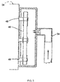
FIG. 5 is a further cross-sectional view of the components ofFIG. 4 ; -
FIG. 6 is a cross-sectional view of a starter motor and the engine block; and -
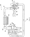
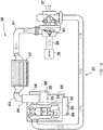
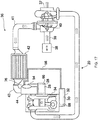
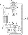
FIGS. 7-18 are schematic views of various embodiments of the engine including a pressuring system which incorporates the features of the invention. - An
engine 20 for avehicle 22 is provided which has apressuring system 24 for pressuring acavity 26 formed by atiming belt cover 28, and may be used to pressurize acavity 30 formed as part of thestarter motor 32 to minimize or prevent water and/or debris entry into thecavities vehicle 22 is submerged, to prevent water, for example rainwater, and/or debris entry when thevehicle 22 is running on land, or dust/debris entry into thecavities vehicle 22 is running with heavy dust. Thepressuring system 24 introduces gases under pressure into thecavities cavities cavities - The
engine 20 has anengine block 34 which include the customary components for enabling operation of thevehicle 22. The specific components which relate to thepressuring system 24 are specifically discussed herein. - In a
typical engine 20, gases flows from atmosphere through anintake system 36 to theengine block 34. Waste gases travel from theengine block 34 to anoutlet 37. Theintake system 36 includes anair filter 38 which receives gases from the atmosphere, anair hose 39 between theair filter 38 and a turbocompressor inlet, aturbocompressor 40 which receives the gases from the turbocompressor inlet and compresses the gases, anair hose 41 between theturbocompressor 40 and an air cooler inlet, anair cooler 42 which receives the compressed gases from the air cooler inlet to cool the compressed gases generated by theturbocompressor 40, anair hose 43 between theair cooler 42 and an intake manifold inlet, and anintake manifold 44 which receives the cooled gases from theair cooler 42. The cooled compressed gases flow through theintake manifold 44 and into theengine block 34 for use by theengine 20 in a typical manner. The pressure of the gases in theintake manifold 44 is greater than ambient. - The
timing belt cover 28 is attached to theengine block 34 in a customary manner. Atiming belt 46, which is used in operating theengine 20 in a known manner, is mounted within thecavity 26. Thetiming belt 46 is driven in a conventional manner and includesoperating components 48, such as crank shafts, sprockets, pulleys, bearings, oil seals, etc., which are mounted within thecavity 26 and interact with the components in theengine block 34. Thetiming belt cover 28 is not completely sealed to theengine block 34. Thetiming belt 46 and itscomponents 48 are not designed to operate in a submerged situation. - The
starter motor 32 is attached to theengine block 34 in a customary manner. Thecomponents 50 of thestarter motor 32 are mounted within thecavity 30 which is formed by astarter motor cover 52.Starter motors 32 are normally protected against water intrusion, but thestarter motor cover 52 is not completely sealed against water intrusion. Astarter motor 32 is not designed to operate in a submerged situation. - As shown in the figures, the
pressuring system 24 includes agases pipe 54 which extends between theintake manifold 44 and thetiming belt cover 28 for feeding pressurized gases from theintake manifold 44 to thetiming belt cavity 26. Thegases pipe 54 is sealed to theintake manifold 44 and to thetiming belt cover 28 and suitable connectors (not shown) may be provided to effect these connections. When pressurized gases are introduced into thecavity 26, a substantially permanent overpressure is generated in thecavity 26 and minimizes the entry of water and/or dust and/or debris and the like into thecavity 26 through any air gaps in thetiming belt cover 28. - In embodiments shown in
FIGS. 8 ,11 and14 , in addition to thegases pipe 54, thepressuring system 24 may also include agases pipe 56 which extends between theintake manifold 44 and thestarter motor cover 52 for feeding pressurized gases from theintake manifold 44 to thecavity 30 formed within thestarter motor 32. Thegases pipe 56 is sealed to theintake manifold 44 and to thestarter motor cover 52 and suitable connectors (not shown) may be provided to effect these connections. When pressurized gases are introduced into thecavity 30, a substantially permanent overpressure is generated in thecavity 30 and minimizes the entry of entry of water and/or dust and/or debris and the like into thecavity 30 through any air gaps in thestarter motor cover 52. In an embodiment, thegases pipes intake manifold 44, a first branch of the gases pipe extends to thetiming belt cover 28, and a second branch extends to thestarter motor cover 52. Thegases pipe intake manifold 44, thetiming belt cover 28 and thestarter motor cover 52 and suitable connectors (not shown) may be provided to effect these connections. Therefore, pressurized gases flows from theintake manifold 44 to pressurize both thecavities cavities cavities cavities timing belt cover 28 and in thestarter motor cover 52. - In embodiments shown in
FIGS. 9 ,12 and15 , thefirst gases pipe 54 extends from theintake manifold 44 to thetiming belt cover 28, and thesecond gases pipe 56 extends from thetiming belt cover 28 to thestarter motor cover 52. Thegases pipe 54 is sealed to theintake manifold 44 and to thetiming belt cover 28 and suitable connectors (not shown) may be provided to effect these connections. Thegases pipe 56 is sealed to theintake manifold 44 and to thestarter motor cover 52 and suitable connectors (not shown) may be provided to effect these connections. Therefore, pressurized gases flows from theintake manifold 44 to pressurize both thecavities cavities cavities cavities timing belt cover 28 and in thestarter motor cover 52. - In the embodiments shown in
FIGS. 7-9 , thepressuring system 24 is a closed-loop feedback system and/or method. In these embodiment, thepressuring system 24 includes acontrol valve 58 and apressure sensor 60, both of which are in communication with an electronic control module (ECM) 62. As shown, thecontrol valve 58 is mounted on theintake manifold 44. In the embodiments shown inFIGS. 7 and9 , thecontrol valve 58 may be mounted on thegases pipe 54. Thepressure sensor 60 may be mounted along thegases pipe 54, in thetiming belt cover 28, and/or in theintake manifold 44. If pressurization is provided to thestarter motor 32, apressure sensor 64, seeFIGS. 8 and9 , may be provided along thegases pipe 56 or in thestarter motor cover 52 and/or in theintake manifold 44. Thepressure sensor 64 is not required. The pressure sensor(s) 60, 64 measures the gases pressure and sends information to theECM 62. TheECM 62 processes the information and is configured to control the opening and the closing of thecontrol valve 58 to appropriately supply gases to the cavity(ies) 26, 30 as necessary for the required amount of pressurization. These embodiments provide a high level of control and may serve to minimize the amount of pressurized gases needed to combat water intrusion, thereby minimizing impact on the performance of theengine 20. - In the embodiments shown in
FIGS. 10-12 , thecontrol valve 58 is eliminated and thepressuring system 24 includes apressure relief valve 66 mounted on thetiming belt cover 28. Gases are always supplied to thetiming belt cover 28 viagases pipe 54. Thepressure relief valve 66 opens when the pressure exceeds a predetermined pressure; this minimizes the impact on the oil seals in thetiming belt 46 which can operate with limited positive pressure. If pressurization is provided to thestarter motor 32 viagases pipe 56 as shown inFIGS. 11 and12 , apressure relief valve 68 may also be provided on thestarter motor cover 52. Thepressure relief valve 68 opens when the pressure exceeds a predetermined pressure. The pressure relief valve(s) 66, 68 is a mechanical valve which automatically opens under a predetermined gases pressure and closes when the pressure is reduced to a level below this predetermined gases pressure. Such pressure relief valves are known in the art. Alternatively, thestarter motor 32 may not have a separatepressure relief valve 68, and the amount of pressurized gases delivered to thestarter motor 32 is controlled by the size of thegases pipe 56 and known levels of leakage to provide the appropriate amount of pressurization. - In the embodiments shown in
FIGS. 13-15 , thecontrol valve 58, thepressure sensor 60 and thepressure relief valve 66 are provided. Thecontrol valve 58 andpressure sensor 60 are in communication with theECM 62 and thecontrol valve 58 is operated by theECM 62. As shown inFIGS. 14 and15 , thepressure sensor 64 andpressure relief valve 68 may also be included. In these embodiments, if the pressuringsystem 24 experiences dramatic dynamic pressure changes, thepressure relief valves control valve 58 can provide under control by theECM 62. - The embodiments shown in
FIGS. 16-18 are identical to those ofFIGS. 10-12 with the exception that acheck valve 76 is mounted on theintake manifold 44 at the point where thegases pipe 54 and/or 56 are provided. Thecheck valve 76 may take the form of a diaphragm. Thecheck valve 76 control gases flowing to the gases pipe(s) 54 and/or 56 from theintake manifold 44. Thecheck valve 76 is a mechanical valve which automatically opens when a positive pressure difference between theintake manifold 44 and gases pipe(s) 54 and/or 56 occurs and closes when the pressure is reduced to a predetermined level. The gases only flow from theintake manifold 44 through thecheck valve 76 to the gases pipe(s) 54 and/or 56, and do not return through thecheck valve 76 to theintake manifold 44. Such check valves are known in the art. - The
control valve 58 can be electric-controlled or vacuum-controlled. When thecontrol valve 58 is electric-controlled, thecontrol valve 58 is electrically driven; may have an actuator controlling the valve position; the control may be accomplished through a solenoid, stepper motor, or other electric control device. When thecontrol valve 58 is vacuum-controlled, in some embodiments, a vacuum pump may be fitted to theengine 20 or to the alternator to generate the vacuum pressure, controlling thecontrol valve 58. Whether electric-controlled or vacuum-controlled, thecontrol valve 58 may be an "on/off" control valve 58 (either open or closed), or may be a progressive/continuous control valve 58 capable of stopping at any position (or discrete positions) along the spectrum between open and closed. The progressive/continuous control valve 58 may be controlled by theECM 62 or by an algorithm incorporated into main vehicle electronic control module (not shown) to keep gases pressure in thecavity 26 in thetiming belt cover 28 at the desired level. - In an embodiment, a
water sensor 70 may be provided to automatically operate thecontrol valve 58 when thevehicle 22 is submerged. Thewater sensor 70 may be provided on thevehicle 22 or on theengine 20 to sense when thewater sensor 70 is submerged which indicates that theengine 20 is submerged. Thewater sensor 70 is connected to theECM 62 and information from thewater sensor 70 is processed by theECM 62 and theECM 62 is configured to operate thecontrol valve 58 to divert pressurized gases from theintake manifold 44 to thetiming belt cover 28 and, in some embodiments, to thestarter motor cover 52. In an embodiment, aswitch 72 on thevehicle dashboard 74 is provided which is connected to theECM 62 to manually operate thecontrol valve 58 prior to submergence of thevehicle 22. Before submergence, thevehicle 22 operator activates theswitch 72; this information is communicated to theECM 62 and theECM 62 is configured to operate thecontrol valve 58. In these embodiments, when thevehicle 22 is operating under a normal operating condition (e.g. not submerged), theengine 20 performance is not affected because gases are not diverted to thetiming belt cover 28 and in some embodiments to thestarter motor 32. - Air is routed from the
intake manifold 44 to the cavity(ies) 26, 30 after theair cooler 42 so that cool air is supplied to the cavity(ies) 26, 30 to prevent damage to the components housed therein. - The systems, methods, etc. described above may be implemented in many different ways in many different combinations of hardware, software, firmware, or any combination thereof. In one example, the
ECM 62 of the pressurizingsystem 24 can be implemented with a processor and a memory, where the memory stores instructions, which when executed by the processor, causes the processor to perform the systems and methods, etc. - The
ECM 62 can control opening and the closing of thecontrol valve 58 to appropriately supply gases to the cavity(ies) 26, 30 based on various thresholds, parameters, tables, and/or algorithms for determined implementations of the pressurizingsystem 24. Additionally or alternatively, theECM 62 may include an interface through which a user may interact with thecontrol valve 58. TheECM 62 may be configured to receive inputs from a user through the interface to allow a user to set or modify one or more thresholds, tables, or algorithms. TheECM 62 may be configured to receive inputs from a user through the interface to allow the user to determine which parameters may be used to open and close thecontrol valve 58. Other variations are possible. - When the
ECM 62 determines the specifications for operating the pressurizingsystem 24, such as when or in what manner to open and close thecontrol valve 58, theECM 62 may send a signal or instructions to the components of the pressurizingsystem 24 to operate according to the determined specification. For example, theECM 62 may send signals to thecontrol valve 58 when it is time for the control value to open or close. In other examples, theECM 62 may not directly instruct a component to operate according to the determined specifications, but may instead instruct an intermediary component, e.g., an engine control unit, to operate the desired component (e.g., the control valve 58). In still other examples, theECM 62 may operate the desired components themselves according to the determined specifications. Other variations and examples are possible. - The
ECM 62 may include, or be connected with, a user interface or display. The display may provide a visual or audible indicator to a user based on the sensed parameters. This may be useful where a user wishes to monitor parameters or the status of the pressurizingsystem 24, and/or where the user may wish to manually control parts of the pressurizingsystem 24. As an example, a user may turn on the pressurizingsystem 24 when a first light on the display is on (or in another state, such as a different color, flashing pattern, or sequence), e.g., noting water and/or debris entering into thecavities ECM 62 determines, based on a sensed parameter, that the pressurizingsystem 24 may be terminated, e.g., when the environment is clear of water and/or debris. The second light may remain on until the user turns off the pressurizingsystem 24. In other examples, the display may provide information about the sensed parameter, information about the operation of the pressurizingsystem 24 such as its operating history and its present operating conditions, information about a load, or various other information. Other examples are possible. Additionally or alternatively, theECM 62 can automatically turn on and off the pressurizingsystem 24, e.g., based on the sensed operating parameters. - The systems, methods, devices, and logic described above may be implemented in many different ways in many different combinations of hardware, software or both hardware and software. For example, parts of the pressurizing
system 24, including theECM 62, may include circuitry in a controller, a microprocessor, or an application specific integrated circuit (ASIC), or may be implemented with discrete logic or components, or a combination of other types of analog or digital circuitry, combined on a single integrated circuit or distributed among multiple integrated circuits. All or part of the logic described above may be implemented as instructions for execution by a processor, controller, or other processing device and may be stored in a tangible or non-transitory machine-readable or computer-readable medium such as flash memory, random access memory (RAM) or read only memory (ROM), erasable programmable read only memory (EPROM) or other machine-readable medium such as a compact disc read only memory (CDROM), or magnetic or optical disk. A product, such as a computer program product, may include a storage medium and computer readable instructions stored on the medium, which when executed in an endpoint, computer system, or other device, cause the device to perform operations according to any of the description above. - The processing capability of the system may be distributed among multiple system components, such as among multiple processors and memories, optionally including multiple distributed processing systems. Parameters, databases, and other data structures may be separately stored and managed, may be incorporated into a single memory or database, may be logically and physically organized in many different ways, and may implemented in many ways, including data structures such as linked lists, hash tables, or implicit storage mechanisms. Programs may be parts (e.g., subroutines) of a single program, separate programs, distributed across several memories and processors, or implemented in many different ways, such as in a library, such as a shared library (e.g., a dynamic link library (DLL)). The DLL, for example, may store code that performs any of the system processing described above.
- The methods described may include determinations in relation to one or more thresholds. While these methods may refer to a determination about whether a parameter exceeds a threshold, the determination may in other variations be whether the parameter is greater than or equal to, less than, equal to, or less than or equal to a threshold.
Claims (15)
- A vehicle engine (20) having a pressuring system (24) comprising:- an intake manifold (44) into which ambient gases flows;- a control valve (58) connected to the intake manifold (44);- an engine block (34) connected to the intake manifold (44) and connected to a gases outlet (37);- a timing belt cover (28) connected to the engine block (34) and forming a timing belt cavity (26);- a timing belt (46) mounted within the timing belt cavity (26); and- a gases pipe (54) connected between the control valve (58) and the timing belt cover (28) for feeding pressurized gases from the intake manifold (44) to the timing belt cavity (26).
- The vehicle engine (20) of claim 1, further comprising a starter motor (32) connected to the engine block (34), the starter motor (32) having a starter motor cover (52); and
wherein the gases pipe (54) is further connected between the control valve (58) and the starter motor cover (52). - The vehicle engine (20) of claim 2, further comprising a pressure relief valve (66) mounted on the starter motor cover (52).
- The vehicle engine (20) of claim 1, further comprising a starter motor (32) connected to the engine block (34), the starter motor (32) having a starter motor cover (52); and
a second gases pipe (56) connected between the timing belt cover (28) and the starter motor cover (52). - The vehicle engine (20) of claim 4, further comprising a pressure relief valve (66) mounted on the starter motor cover (52).
- The vehicle engine (20) of claim 1, wherein the control valve (58) is electrically controlled.
- The vehicle engine (20) of claim 1, wherein the control valve (58) is vacuum controlled.
- The vehicle engine (20) of claim 1, further comprising an electronic control module (62) connected to the control valve (58) and configured to operate the control valve (58).
- The vehicle engine (20) of claim 8, further comprising a water sensor (70) connected to the electronic control module (62), wherein the electronic control module (62) is configured to process information received from the water sensor and control operation of the control valve (58) based on the processed information.
- The vehicle engine (20) of claim 1, wherein the control valve (58) is activated by a manually controllable switch (72).
- The vehicle engine (20) of claim 1, further comprising a pressure relief valve (66) mounted on the timing belt cover (28).
- The vehicle engine (20) of claim 1, further comprising a turbocompressor (40) which compressed air from the atmosphere, wherein a first portion of the compressed air is used for combustion and a second portion of the compressed air pressurizes the timing belt cavity (26).
- The vehicle engine (20) of claim 12, further comprising an air cooler (42) positioned between the turbocompressor (40) and the intake manifold (44), the air cooler (42) configured to cool the compressed air.
- The vehicle engine (20) of claim 8, wherein the electronic control module (62) controls a progressive control valve (58) to maintain a pressure in the timing belt cavity (26) at a desired level.
- The vehicle engine (20) of claim 8, further comprising an interface through which a user may interact with the electronic control module (62) to manipulate the control valve (58) and dynamically control a pressure in the timing belt cavity (26).
Applications Claiming Priority (1)
| Application Number | Priority Date | Filing Date | Title |
|---|---|---|---|
| ITUB2015A003096A ITUB20153096A1 (en) | 2015-08-13 | 2015-08-13 | Pressurization system for engine components of a vehicle for water protection |
Publications (2)
| Publication Number | Publication Date |
|---|---|
| EP3130772A1 EP3130772A1 (en) | 2017-02-15 |
| EP3130772B1 true EP3130772B1 (en) | 2018-09-19 |
Family
ID=54364615
Family Applications (1)
| Application Number | Title | Priority Date | Filing Date |
|---|---|---|---|
| EP16183100.3A Active EP3130772B1 (en) | 2015-08-13 | 2016-08-05 | Pressuring system for a vehicle engine components for water protection |
Country Status (4)
| Country | Link |
|---|---|
| US (1) | US9945304B2 (en) |
| EP (1) | EP3130772B1 (en) |
| CN (1) | CN106438150B (en) |
| IT (1) | ITUB20153096A1 (en) |
Families Citing this family (1)
| Publication number | Priority date | Publication date | Assignee | Title |
|---|---|---|---|---|
| US12202490B2 (en) * | 2019-06-25 | 2025-01-21 | Honda Motor Co., Ltd. | Vehicle, vehicle control method, and program |
Family Cites Families (29)
| Publication number | Priority date | Publication date | Assignee | Title |
|---|---|---|---|---|
| US2429732A (en) | 1945-01-04 | 1947-10-28 | Willys Overland Motors Inc | System and apparatus for operating submerged internal-combustion engines |
| FR918023A (en) * | 1945-01-04 | 1947-01-28 | Willys Overland Motors | Device allowing the operation of an internal combustion engine in a state of immersion |
| US2782773A (en) * | 1953-08-18 | 1957-02-26 | Bank Of America Nat Trust & Savings Ass | Pressurizing and ventilating system and apparatus for internal-combustion engines and transmission mechanisms |
| US2822790A (en) * | 1955-05-26 | 1958-02-11 | Kloeckner Humboldt Deutz Ag | Internal combustion engine |
| US2775960A (en) | 1955-08-17 | 1957-01-01 | Continental Motors Corp | Crankcase breather system |
| US2982980A (en) | 1958-04-29 | 1961-05-09 | United Shoe Machinery Corp | Lasting machines |
| US3477413A (en) * | 1968-03-25 | 1969-11-11 | Continental Motors Corp | Crankcase breather system and structure |
| US4098238A (en) * | 1976-01-28 | 1978-07-04 | Alto Automotive, Inc. | Rotary valve system for motors and the like having improved sealing means |
| US4497285A (en) | 1981-09-09 | 1985-02-05 | Honda Giken Kogyo Kabushiki Kaisha | Cooling structure for internal combustion engine |
| SE431359B (en) | 1982-06-14 | 1984-01-30 | Stal Laval Turbin Ab | GASTURBINANLEGGNING |
| DE3635755A1 (en) * | 1985-10-21 | 1987-04-23 | Honda Motor Co Ltd | ADDITIONAL DEVICE MOUNTING CONSTRUCTION FOR A V-SHAPED ENGINE |
| US4693452A (en) * | 1986-03-12 | 1987-09-15 | Triten Corporation | Valve |
| DE3631517A1 (en) | 1986-09-17 | 1988-04-14 | Konrad Dipl Ing Schmidt | ONE OR MULTI-PIECE PROTECTIVE FAIRING FOR TENSION GEARBOXES |
| JPH01182192A (en) * | 1988-01-14 | 1989-07-20 | Toohatsu Kk | Outboard motor |
| US5375569A (en) * | 1994-01-26 | 1994-12-27 | General Electric Company | Multi polymer structures for internal combustion engines |
| US5490485A (en) * | 1994-06-14 | 1996-02-13 | Kutlucinar; Iskender V. | Rotary valve for internal combustion engine |
| JP3743233B2 (en) * | 1999-12-03 | 2006-02-08 | スズキ株式会社 | Outboard flywheel structure |
| WO2005077089A2 (en) | 2004-02-10 | 2005-08-25 | Bush Hog, Llc | Positive air flow drive train unit for utility vehicle |
| JP4583338B2 (en) * | 2006-06-05 | 2010-11-17 | 本田技研工業株式会社 | Vertical internal combustion engine having a belt-type transmission mechanism |
| DE102007008814B3 (en) * | 2007-02-22 | 2008-11-06 | Voith Patent Gmbh | starter |
| JP4183014B1 (en) | 2007-05-28 | 2008-11-19 | トヨタ自動車株式会社 | Motor insulation protection device and vehicle having the same |
| MY154609A (en) | 2008-01-08 | 2015-07-15 | Reynolds Richard Arthur Henry | Turbine assembly |
| US8047226B2 (en) * | 2008-06-18 | 2011-11-01 | Honeywell International Inc. | Pressure relief valves and pneumatic control systems |
| DE102009032112B4 (en) | 2009-07-08 | 2024-08-01 | Dr. Ing. H.C. F. Porsche Aktiengesellschaft | Device for sealing a housing of a component of a motor vehicle drive train designed as a hybrid module |
| JP5440799B2 (en) * | 2010-12-28 | 2014-03-12 | 三菱自動車工業株式会社 | Engine control device |
| DE102012108857B4 (en) * | 2012-09-20 | 2022-01-13 | Linde Hydraulics Gmbh & Co. Kg | Hydrostatic starter device for an internal combustion engine |
| US20140338631A1 (en) * | 2013-05-17 | 2014-11-20 | Benjamin Ellis | Internal combustion engines and related methods |
| CN203571060U (en) * | 2013-10-10 | 2014-04-30 | 潍柴动力股份有限公司 | Engine air inlet system and automatic drain valve thereof |
| JP6146405B2 (en) * | 2014-12-26 | 2017-06-14 | トヨタ自動車株式会社 | Engine and engine manufacturing method |
-
2015
- 2015-08-13 IT ITUB2015A003096A patent/ITUB20153096A1/en unknown
-
2016
- 2016-08-05 EP EP16183100.3A patent/EP3130772B1/en active Active
- 2016-08-10 CN CN201610654084.XA patent/CN106438150B/en not_active Expired - Fee Related
- 2016-08-12 US US15/235,563 patent/US9945304B2/en active Active
Non-Patent Citations (1)
| Title |
|---|
| None * |
Also Published As
| Publication number | Publication date |
|---|---|
| US20170045006A1 (en) | 2017-02-16 |
| US9945304B2 (en) | 2018-04-17 |
| EP3130772A1 (en) | 2017-02-15 |
| ITUB20153096A1 (en) | 2017-02-13 |
| CN106438150A (en) | 2017-02-22 |
| CN106438150B (en) | 2018-09-18 |
Similar Documents
| Publication | Publication Date | Title |
|---|---|---|
| CN106062328B (en) | Method and crankcase ventilation system for removing leaked crankcase fluid from a crankcase | |
| KR20020081402A (en) | Idle shutdown override with defeat protection | |
| US20080233812A1 (en) | Controller for boat propulsion system and boat propulsion system | |
| US10934963B2 (en) | Abnormality assessment device of internal combustion engine | |
| US9945304B2 (en) | Pressuring system for a vehicle engine components for water protection | |
| EP0269500B1 (en) | Plunger pump of quick pressure-rise type | |
| US8105123B2 (en) | Marine electric generator flushing system | |
| US8528516B2 (en) | Oil tank breather line solenoid valve | |
| US20040208754A1 (en) | Speed regulated oil delivery system | |
| JP2019143529A (en) | Control device and control method | |
| US6773317B2 (en) | Method and system for preventing fluid from flowing along a fluid path in a watercraft | |
| US9303537B2 (en) | Oil tank breather line solenoid valve | |
| GB2525060A (en) | A system for pressurizing a cooling circuit of an internal combustion engine equipped with a turbocompressor unit | |
| US4732123A (en) | Safety air supply for diesel engine shutdown systems | |
| JP2018151009A (en) | Hydraulic circuit | |
| JPH08218929A (en) | Overheat prevention device for diesel engine | |
| US20190186303A1 (en) | Oil supply device for a vacuum pump of an internal combustion engine | |
| AU2018253619B2 (en) | Boost Device Diverter Valve System | |
| KR102225066B1 (en) | Method for operating a low pressure pump | |
| JP4164868B2 (en) | Fuel vapor leak inspection module | |
| KR200401919Y1 (en) | A system of preventing a fuel tank from fire in vehicle | |
| EP3551863B1 (en) | A cooling system valve | |
| EP2927455B1 (en) | Pressurization system of a cooling circuit of a utility vehicle | |
| JP4211058B2 (en) | Fuel vapor leak inspection module | |
| SE508505C2 (en) | Valve arrangement, method for controlling a valve arrangement and valve device for preventing siphoning action on a motor with a water supply line |
Legal Events
| Date | Code | Title | Description |
|---|---|---|---|
| PUAI | Public reference made under article 153(3) epc to a published international application that has entered the european phase |
Free format text: ORIGINAL CODE: 0009012 |
|
| STAA | Information on the status of an ep patent application or granted ep patent |
Free format text: STATUS: THE APPLICATION HAS BEEN PUBLISHED |
|
| AK | Designated contracting states |
Kind code of ref document: A1 Designated state(s): AL AT BE BG CH CY CZ DE DK EE ES FI FR GB GR HR HU IE IS IT LI LT LU LV MC MK MT NL NO PL PT RO RS SE SI SK SM TR |
|
| AX | Request for extension of the european patent |
Extension state: BA ME |
|
| STAA | Information on the status of an ep patent application or granted ep patent |
Free format text: STATUS: REQUEST FOR EXAMINATION WAS MADE |
|
| 17P | Request for examination filed |
Effective date: 20170804 |
|
| RBV | Designated contracting states (corrected) |
Designated state(s): AL AT BE BG CH CY CZ DE DK EE ES FI FR GB GR HR HU IE IS IT LI LT LU LV MC MK MT NL NO PL PT RO RS SE SI SK SM TR |
|
| RIC1 | Information provided on ipc code assigned before grant |
Ipc: B60F 3/00 20060101ALI20180306BHEP Ipc: F01M 13/06 20060101AFI20180306BHEP |
|
| GRAP | Despatch of communication of intention to grant a patent |
Free format text: ORIGINAL CODE: EPIDOSNIGR1 |
|
| STAA | Information on the status of an ep patent application or granted ep patent |
Free format text: STATUS: GRANT OF PATENT IS INTENDED |
|
| INTG | Intention to grant announced |
Effective date: 20180416 |
|
| GRAS | Grant fee paid |
Free format text: ORIGINAL CODE: EPIDOSNIGR3 |
|
| GRAA | (expected) grant |
Free format text: ORIGINAL CODE: 0009210 |
|
| STAA | Information on the status of an ep patent application or granted ep patent |
Free format text: STATUS: THE PATENT HAS BEEN GRANTED |
|
| AK | Designated contracting states |
Kind code of ref document: B1 Designated state(s): AL AT BE BG CH CY CZ DE DK EE ES FI FR GB GR HR HU IE IS IT LI LT LU LV MC MK MT NL NO PL PT RO RS SE SI SK SM TR |
|
| REG | Reference to a national code |
Ref country code: GB Ref legal event code: FG4D |
|
| REG | Reference to a national code |
Ref country code: CH Ref legal event code: EP |
|
| REG | Reference to a national code |
Ref country code: AT Ref legal event code: REF Ref document number: 1043494 Country of ref document: AT Kind code of ref document: T Effective date: 20181015 |
|
| REG | Reference to a national code |
Ref country code: IE Ref legal event code: FG4D |
|
| REG | Reference to a national code |
Ref country code: DE Ref legal event code: R096 Ref document number: 602016005688 Country of ref document: DE |
|
| REG | Reference to a national code |
Ref country code: NL Ref legal event code: MP Effective date: 20180919 |
|
| PG25 | Lapsed in a contracting state [announced via postgrant information from national office to epo] |
Ref country code: FI Free format text: LAPSE BECAUSE OF FAILURE TO SUBMIT A TRANSLATION OF THE DESCRIPTION OR TO PAY THE FEE WITHIN THE PRESCRIBED TIME-LIMIT Effective date: 20180919 Ref country code: SE Free format text: LAPSE BECAUSE OF FAILURE TO SUBMIT A TRANSLATION OF THE DESCRIPTION OR TO PAY THE FEE WITHIN THE PRESCRIBED TIME-LIMIT Effective date: 20180919 Ref country code: BG Free format text: LAPSE BECAUSE OF FAILURE TO SUBMIT A TRANSLATION OF THE DESCRIPTION OR TO PAY THE FEE WITHIN THE PRESCRIBED TIME-LIMIT Effective date: 20181219 Ref country code: NO Free format text: LAPSE BECAUSE OF FAILURE TO SUBMIT A TRANSLATION OF THE DESCRIPTION OR TO PAY THE FEE WITHIN THE PRESCRIBED TIME-LIMIT Effective date: 20181219 Ref country code: LT Free format text: LAPSE BECAUSE OF FAILURE TO SUBMIT A TRANSLATION OF THE DESCRIPTION OR TO PAY THE FEE WITHIN THE PRESCRIBED TIME-LIMIT Effective date: 20180919 Ref country code: RS Free format text: LAPSE BECAUSE OF FAILURE TO SUBMIT A TRANSLATION OF THE DESCRIPTION OR TO PAY THE FEE WITHIN THE PRESCRIBED TIME-LIMIT Effective date: 20180919 Ref country code: GR Free format text: LAPSE BECAUSE OF FAILURE TO SUBMIT A TRANSLATION OF THE DESCRIPTION OR TO PAY THE FEE WITHIN THE PRESCRIBED TIME-LIMIT Effective date: 20181220 |
|
| REG | Reference to a national code |
Ref country code: LT Ref legal event code: MG4D |
|
| PG25 | Lapsed in a contracting state [announced via postgrant information from national office to epo] |
Ref country code: HR Free format text: LAPSE BECAUSE OF FAILURE TO SUBMIT A TRANSLATION OF THE DESCRIPTION OR TO PAY THE FEE WITHIN THE PRESCRIBED TIME-LIMIT Effective date: 20180919 Ref country code: LV Free format text: LAPSE BECAUSE OF FAILURE TO SUBMIT A TRANSLATION OF THE DESCRIPTION OR TO PAY THE FEE WITHIN THE PRESCRIBED TIME-LIMIT Effective date: 20180919 Ref country code: AL Free format text: LAPSE BECAUSE OF FAILURE TO SUBMIT A TRANSLATION OF THE DESCRIPTION OR TO PAY THE FEE WITHIN THE PRESCRIBED TIME-LIMIT Effective date: 20180919 |
|
| REG | Reference to a national code |
Ref country code: AT Ref legal event code: MK05 Ref document number: 1043494 Country of ref document: AT Kind code of ref document: T Effective date: 20180919 |
|
| PG25 | Lapsed in a contracting state [announced via postgrant information from national office to epo] |
Ref country code: ES Free format text: LAPSE BECAUSE OF FAILURE TO SUBMIT A TRANSLATION OF THE DESCRIPTION OR TO PAY THE FEE WITHIN THE PRESCRIBED TIME-LIMIT Effective date: 20180919 Ref country code: AT Free format text: LAPSE BECAUSE OF FAILURE TO SUBMIT A TRANSLATION OF THE DESCRIPTION OR TO PAY THE FEE WITHIN THE PRESCRIBED TIME-LIMIT Effective date: 20180919 Ref country code: IS Free format text: LAPSE BECAUSE OF FAILURE TO SUBMIT A TRANSLATION OF THE DESCRIPTION OR TO PAY THE FEE WITHIN THE PRESCRIBED TIME-LIMIT Effective date: 20190119 Ref country code: PL Free format text: LAPSE BECAUSE OF FAILURE TO SUBMIT A TRANSLATION OF THE DESCRIPTION OR TO PAY THE FEE WITHIN THE PRESCRIBED TIME-LIMIT Effective date: 20180919 Ref country code: EE Free format text: LAPSE BECAUSE OF FAILURE TO SUBMIT A TRANSLATION OF THE DESCRIPTION OR TO PAY THE FEE WITHIN THE PRESCRIBED TIME-LIMIT Effective date: 20180919 Ref country code: NL Free format text: LAPSE BECAUSE OF FAILURE TO SUBMIT A TRANSLATION OF THE DESCRIPTION OR TO PAY THE FEE WITHIN THE PRESCRIBED TIME-LIMIT Effective date: 20180919 Ref country code: RO Free format text: LAPSE BECAUSE OF FAILURE TO SUBMIT A TRANSLATION OF THE DESCRIPTION OR TO PAY THE FEE WITHIN THE PRESCRIBED TIME-LIMIT Effective date: 20180919 Ref country code: CZ Free format text: LAPSE BECAUSE OF FAILURE TO SUBMIT A TRANSLATION OF THE DESCRIPTION OR TO PAY THE FEE WITHIN THE PRESCRIBED TIME-LIMIT Effective date: 20180919 |
|
| PG25 | Lapsed in a contracting state [announced via postgrant information from national office to epo] |
Ref country code: PT Free format text: LAPSE BECAUSE OF FAILURE TO SUBMIT A TRANSLATION OF THE DESCRIPTION OR TO PAY THE FEE WITHIN THE PRESCRIBED TIME-LIMIT Effective date: 20190119 Ref country code: SM Free format text: LAPSE BECAUSE OF FAILURE TO SUBMIT A TRANSLATION OF THE DESCRIPTION OR TO PAY THE FEE WITHIN THE PRESCRIBED TIME-LIMIT Effective date: 20180919 Ref country code: SK Free format text: LAPSE BECAUSE OF FAILURE TO SUBMIT A TRANSLATION OF THE DESCRIPTION OR TO PAY THE FEE WITHIN THE PRESCRIBED TIME-LIMIT Effective date: 20180919 |
|
| REG | Reference to a national code |
Ref country code: DE Ref legal event code: R097 Ref document number: 602016005688 Country of ref document: DE |
|
| PLBE | No opposition filed within time limit |
Free format text: ORIGINAL CODE: 0009261 |
|
| STAA | Information on the status of an ep patent application or granted ep patent |
Free format text: STATUS: NO OPPOSITION FILED WITHIN TIME LIMIT |
|
| PG25 | Lapsed in a contracting state [announced via postgrant information from national office to epo] |
Ref country code: DK Free format text: LAPSE BECAUSE OF FAILURE TO SUBMIT A TRANSLATION OF THE DESCRIPTION OR TO PAY THE FEE WITHIN THE PRESCRIBED TIME-LIMIT Effective date: 20180919 |
|
| 26N | No opposition filed |
Effective date: 20190620 |
|
| PG25 | Lapsed in a contracting state [announced via postgrant information from national office to epo] |
Ref country code: SI Free format text: LAPSE BECAUSE OF FAILURE TO SUBMIT A TRANSLATION OF THE DESCRIPTION OR TO PAY THE FEE WITHIN THE PRESCRIBED TIME-LIMIT Effective date: 20180919 |
|
| PG25 | Lapsed in a contracting state [announced via postgrant information from national office to epo] |
Ref country code: TR Free format text: LAPSE BECAUSE OF FAILURE TO SUBMIT A TRANSLATION OF THE DESCRIPTION OR TO PAY THE FEE WITHIN THE PRESCRIBED TIME-LIMIT Effective date: 20180919 |
|
| PG25 | Lapsed in a contracting state [announced via postgrant information from national office to epo] |
Ref country code: MC Free format text: LAPSE BECAUSE OF FAILURE TO SUBMIT A TRANSLATION OF THE DESCRIPTION OR TO PAY THE FEE WITHIN THE PRESCRIBED TIME-LIMIT Effective date: 20180919 Ref country code: LU Free format text: LAPSE BECAUSE OF NON-PAYMENT OF DUE FEES Effective date: 20190805 Ref country code: CH Free format text: LAPSE BECAUSE OF NON-PAYMENT OF DUE FEES Effective date: 20190831 Ref country code: LI Free format text: LAPSE BECAUSE OF NON-PAYMENT OF DUE FEES Effective date: 20190831 |
|
| REG | Reference to a national code |
Ref country code: BE Ref legal event code: MM Effective date: 20190831 |
|
| PG25 | Lapsed in a contracting state [announced via postgrant information from national office to epo] |
Ref country code: IE Free format text: LAPSE BECAUSE OF NON-PAYMENT OF DUE FEES Effective date: 20190805 |
|
| PG25 | Lapsed in a contracting state [announced via postgrant information from national office to epo] |
Ref country code: BE Free format text: LAPSE BECAUSE OF NON-PAYMENT OF DUE FEES Effective date: 20190831 |
|
| PG25 | Lapsed in a contracting state [announced via postgrant information from national office to epo] |
Ref country code: CY Free format text: LAPSE BECAUSE OF FAILURE TO SUBMIT A TRANSLATION OF THE DESCRIPTION OR TO PAY THE FEE WITHIN THE PRESCRIBED TIME-LIMIT Effective date: 20180919 |
|
| PG25 | Lapsed in a contracting state [announced via postgrant information from national office to epo] |
Ref country code: MT Free format text: LAPSE BECAUSE OF FAILURE TO SUBMIT A TRANSLATION OF THE DESCRIPTION OR TO PAY THE FEE WITHIN THE PRESCRIBED TIME-LIMIT Effective date: 20180919 Ref country code: HU Free format text: LAPSE BECAUSE OF FAILURE TO SUBMIT A TRANSLATION OF THE DESCRIPTION OR TO PAY THE FEE WITHIN THE PRESCRIBED TIME-LIMIT; INVALID AB INITIO Effective date: 20160805 |
|
| PG25 | Lapsed in a contracting state [announced via postgrant information from national office to epo] |
Ref country code: MK Free format text: LAPSE BECAUSE OF FAILURE TO SUBMIT A TRANSLATION OF THE DESCRIPTION OR TO PAY THE FEE WITHIN THE PRESCRIBED TIME-LIMIT Effective date: 20180919 |
|
| P01 | Opt-out of the competence of the unified patent court (upc) registered |
Effective date: 20230817 |
|
| PGFP | Annual fee paid to national office [announced via postgrant information from national office to epo] |
Ref country code: DE Payment date: 20250827 Year of fee payment: 10 |
|
| PGFP | Annual fee paid to national office [announced via postgrant information from national office to epo] |
Ref country code: GB Payment date: 20250827 Year of fee payment: 10 |
|
| PGFP | Annual fee paid to national office [announced via postgrant information from national office to epo] |
Ref country code: FR Payment date: 20250825 Year of fee payment: 10 |
|
| PGFP | Annual fee paid to national office [announced via postgrant information from national office to epo] |
Ref country code: IT Payment date: 20260626 Year of fee payment: 11 |