EP3130498A1 - Oil filler port opening and closing device - Google Patents
Oil filler port opening and closing device Download PDFInfo
- Publication number
- EP3130498A1 EP3130498A1 EP15777176.7A EP15777176A EP3130498A1 EP 3130498 A1 EP3130498 A1 EP 3130498A1 EP 15777176 A EP15777176 A EP 15777176A EP 3130498 A1 EP3130498 A1 EP 3130498A1
- Authority
- EP
- European Patent Office
- Prior art keywords
- fuel filling
- outside
- opening
- flap
- inlet pipe
- Prior art date
- Legal status (The legal status is an assumption and is not a legal conclusion. Google has not performed a legal analysis and makes no representation as to the accuracy of the status listed.)
- Granted
Links
Images






Classifications
-
- B—PERFORMING OPERATIONS; TRANSPORTING
- B60—VEHICLES IN GENERAL
- B60K—ARRANGEMENT OR MOUNTING OF PROPULSION UNITS OR OF TRANSMISSIONS IN VEHICLES; ARRANGEMENT OR MOUNTING OF PLURAL DIVERSE PRIME-MOVERS IN VEHICLES; AUXILIARY DRIVES FOR VEHICLES; INSTRUMENTATION OR DASHBOARDS FOR VEHICLES; ARRANGEMENTS IN CONNECTION WITH COOLING, AIR INTAKE, GAS EXHAUST OR FUEL SUPPLY OF PROPULSION UNITS IN VEHICLES
- B60K15/00—Arrangement in connection with fuel supply of combustion engines or other fuel consuming energy converters, e.g. fuel cells; Mounting or construction of fuel tanks
- B60K15/03—Fuel tanks
- B60K15/04—Tank inlets
- B60K15/0406—Filler caps for fuel tanks
-
- B—PERFORMING OPERATIONS; TRANSPORTING
- B60—VEHICLES IN GENERAL
- B60K—ARRANGEMENT OR MOUNTING OF PROPULSION UNITS OR OF TRANSMISSIONS IN VEHICLES; ARRANGEMENT OR MOUNTING OF PLURAL DIVERSE PRIME-MOVERS IN VEHICLES; AUXILIARY DRIVES FOR VEHICLES; INSTRUMENTATION OR DASHBOARDS FOR VEHICLES; ARRANGEMENTS IN CONNECTION WITH COOLING, AIR INTAKE, GAS EXHAUST OR FUEL SUPPLY OF PROPULSION UNITS IN VEHICLES
- B60K15/00—Arrangement in connection with fuel supply of combustion engines or other fuel consuming energy converters, e.g. fuel cells; Mounting or construction of fuel tanks
- B60K15/03—Fuel tanks
- B60K15/04—Tank inlets
-
- B—PERFORMING OPERATIONS; TRANSPORTING
- B60—VEHICLES IN GENERAL
- B60K—ARRANGEMENT OR MOUNTING OF PROPULSION UNITS OR OF TRANSMISSIONS IN VEHICLES; ARRANGEMENT OR MOUNTING OF PLURAL DIVERSE PRIME-MOVERS IN VEHICLES; AUXILIARY DRIVES FOR VEHICLES; INSTRUMENTATION OR DASHBOARDS FOR VEHICLES; ARRANGEMENTS IN CONNECTION WITH COOLING, AIR INTAKE, GAS EXHAUST OR FUEL SUPPLY OF PROPULSION UNITS IN VEHICLES
- B60K15/00—Arrangement in connection with fuel supply of combustion engines or other fuel consuming energy converters, e.g. fuel cells; Mounting or construction of fuel tanks
- B60K15/03—Fuel tanks
- B60K15/04—Tank inlets
- B60K15/0406—Filler caps for fuel tanks
- B60K2015/0419—Self-sealing closure caps, e.g. that don't have to be removed manually
- B60K2015/0429—Self-sealing closure caps, e.g. that don't have to be removed manually actuated by the nozzle
-
- B—PERFORMING OPERATIONS; TRANSPORTING
- B60—VEHICLES IN GENERAL
- B60K—ARRANGEMENT OR MOUNTING OF PROPULSION UNITS OR OF TRANSMISSIONS IN VEHICLES; ARRANGEMENT OR MOUNTING OF PLURAL DIVERSE PRIME-MOVERS IN VEHICLES; AUXILIARY DRIVES FOR VEHICLES; INSTRUMENTATION OR DASHBOARDS FOR VEHICLES; ARRANGEMENTS IN CONNECTION WITH COOLING, AIR INTAKE, GAS EXHAUST OR FUEL SUPPLY OF PROPULSION UNITS IN VEHICLES
- B60K15/00—Arrangement in connection with fuel supply of combustion engines or other fuel consuming energy converters, e.g. fuel cells; Mounting or construction of fuel tanks
- B60K15/03—Fuel tanks
- B60K15/04—Tank inlets
- B60K15/0406—Filler caps for fuel tanks
- B60K2015/0432—Filler caps for fuel tanks having a specific connection between the cap and the vehicle or tank opening
- B60K2015/0445—Filler caps for fuel tanks having a specific connection between the cap and the vehicle or tank opening using hinges
-
- B—PERFORMING OPERATIONS; TRANSPORTING
- B60—VEHICLES IN GENERAL
- B60K—ARRANGEMENT OR MOUNTING OF PROPULSION UNITS OR OF TRANSMISSIONS IN VEHICLES; ARRANGEMENT OR MOUNTING OF PLURAL DIVERSE PRIME-MOVERS IN VEHICLES; AUXILIARY DRIVES FOR VEHICLES; INSTRUMENTATION OR DASHBOARDS FOR VEHICLES; ARRANGEMENTS IN CONNECTION WITH COOLING, AIR INTAKE, GAS EXHAUST OR FUEL SUPPLY OF PROPULSION UNITS IN VEHICLES
- B60K15/00—Arrangement in connection with fuel supply of combustion engines or other fuel consuming energy converters, e.g. fuel cells; Mounting or construction of fuel tanks
- B60K15/03—Fuel tanks
- B60K15/04—Tank inlets
- B60K15/0406—Filler caps for fuel tanks
- B60K2015/0451—Sealing means in the closure cap
-
- B—PERFORMING OPERATIONS; TRANSPORTING
- B60—VEHICLES IN GENERAL
- B60K—ARRANGEMENT OR MOUNTING OF PROPULSION UNITS OR OF TRANSMISSIONS IN VEHICLES; ARRANGEMENT OR MOUNTING OF PLURAL DIVERSE PRIME-MOVERS IN VEHICLES; AUXILIARY DRIVES FOR VEHICLES; INSTRUMENTATION OR DASHBOARDS FOR VEHICLES; ARRANGEMENTS IN CONNECTION WITH COOLING, AIR INTAKE, GAS EXHAUST OR FUEL SUPPLY OF PROPULSION UNITS IN VEHICLES
- B60K15/00—Arrangement in connection with fuel supply of combustion engines or other fuel consuming energy converters, e.g. fuel cells; Mounting or construction of fuel tanks
- B60K15/03—Fuel tanks
- B60K15/04—Tank inlets
- B60K2015/0458—Details of the tank inlet
- B60K2015/0461—Details of the tank inlet comprising a filler pipe shutter, e.g. trap, door or flap for fuel inlet
-
- B—PERFORMING OPERATIONS; TRANSPORTING
- B60—VEHICLES IN GENERAL
- B60K—ARRANGEMENT OR MOUNTING OF PROPULSION UNITS OR OF TRANSMISSIONS IN VEHICLES; ARRANGEMENT OR MOUNTING OF PLURAL DIVERSE PRIME-MOVERS IN VEHICLES; AUXILIARY DRIVES FOR VEHICLES; INSTRUMENTATION OR DASHBOARDS FOR VEHICLES; ARRANGEMENTS IN CONNECTION WITH COOLING, AIR INTAKE, GAS EXHAUST OR FUEL SUPPLY OF PROPULSION UNITS IN VEHICLES
- B60K15/00—Arrangement in connection with fuel supply of combustion engines or other fuel consuming energy converters, e.g. fuel cells; Mounting or construction of fuel tanks
- B60K15/03—Fuel tanks
- B60K15/04—Tank inlets
- B60K2015/0458—Details of the tank inlet
- B60K2015/0483—Means to inhibit the introduction of too small or too big filler nozzles
Definitions
- the present invention relates to a fuel filling aperture opening and closing device opening a fuel filling aperture by an insertion of a fuel filling nozzle to allow the insertion, and automatically closing the fuel filling aperture when the inserted fuel filling nozzle is pulled out.
- an opening and closing device As for an opening and closing device attached to an upper end of a fuel injection pipe, there is an opening and closing device shown in Patent Document 1.
- the opening and closing device includes a closing member turnably assembled relative to a main member, and such closing member closes an open portion from a back side of the fuel injection pipe by urging of a spring device.
- the closing member can contact a seal member provided on an upper face thereof with a seating face.
- the seal member has a Y shape in cross section, and this shape lowers a sealing performance when the back side of the fuel injection pipe, i.e. the inner side of a fuel tank has a pressure lower than that of the outside of the fuel tank.
- this kind of seal member is made of a material having elasticity and easily swelling by fuel, so that in a case wherein the fuel is attached to the seal member, due to the aforementioned swelling, there causes a change at a position where the aforementioned seating face and seal member contact. This becomes a factor affecting a valve opening pressure of this kind of opening and closing device.
- Patent Document 1 Japanese Unexamined Patent Application Publication No. 2010-522118
- a main object of the present invention is to improve a sealing performance of the fuel filling aperture when it is closed by this kind of fuel filling aperture opening and closing device so as to make more reliable and excellent.
- a fuel filling aperture opening and closing device is an opening and closing device comprising a closing member turned to an open position by an insertion of a fuel filling nozzle to open a fuel filling aperture, and the closing member is provided with a flap member including a ring-shaped seal member, and an urging device urging the flap member to be positioned at a closed position.
- the seal member is provided with seal portions respectively inside and outside, and one of the inner and outer seal portions is a plate-shaped portion pressed by the aforementioned urging against a projection piece bordering an opening edge portion of a pass-through opening of the fuel filling nozzle, and the other of the inner and outer seal portions is formed by an inside circumferential projecting portion and an outside circumferential projecting portion respectively pressed against the flap member.
- the other of the inner and outer seal portions of the seal member is formed by the inside circumferential projecting portion and outside circumferential projecting portion, so that not only when a back side of an inlet pipe has a high pressure, but also when the outside of the inlet pipe has a high pressure, one of the inside circumferential projecting portion and outside circumferential projecting portion, which is positioned on a higher pressure side, is pressed against the flap member by a pressure difference so as to enhance a sealing performance between the seal member and the flap member.
- the flap member is formed by an outside member and an inside member combined through the seal member; the plate-shaped portion of the seal member is positioned on an outer side of the outside member; and the inside circumferential projecting portion and outside circumferential projecting portion of the seal member are positioned between the inside member and the outside member.
- one of the preferred aspects of the present invention is that in the inside member, there is formed a communication hole communicating a space between the inner and outer seal portions to the back side of the inlet pipe.
- the seal member has an approximately L shape in cross section including a portion intersecting an axial direction of the inlet pipe, and a portion along the axial direction of the inlet pipe; and one portion of the portion intersecting the axial direction is the plate-shaped portion, and the inside circumferential projecting portion and outside circumferential projecting portion are provided at a terminal of the portion along the axial direction.
- one of the preferred aspects of the present invention is that the plate-shaped portion of the seal member is deformed in a direction of enhancing a firmly contacting performance relative to the projection piece bordering the opening edge portion of the pass-through opening when the back side of the inlet pipe has the high pressure.
- An fuel filling aperture opening and closing device opens a fuel filling aperture by an insertion of a fuel filling nozzle N to allow the insertion, and automatically closes the fuel filling aperture when the inserted fuel filling nozzle N is pulled out.
- the fuel filling aperture opening and closing device is attached to an upper end portion Pa forming the fuel filling aperture of an inlet pipe P (a fuel injection pipe) (see Fig. 4 ).
- an inlet pipe P a fuel injection pipe
- two kinds of fuel filling aperture opening and closing devices having different functions.
- One of such two kinds of fuel filling aperture opening and closing devices is fitted into an inside of the upper end portion Pa of the inlet pipe P (hereinafter, such one fuel filling aperture opening and closing device is called a lower-side device L).
- the lower-side device L is fitted into an outside of the upper end portion Pa of the inlet pipe P from a state fitted into the upper end portion Pa of the inlet pipe P (hereinafter, such other fuel filling aperture opening and closing device is called an upper-side device U).
- an upper-side device U such other fuel filling aperture opening and closing device is called an upper-side device U.
- the fuel filling nozzle N abuts against the closing member Ua of the upper-side device U to turn the closing member Ua to the open position so as to enter into the fuel filling aperture, and then, abuts against the closing member La of the lower-side device L to turn the closing member La to the open position so as to completely open the fuel filling aperture.
- the aforementioned lower-side device L is provided with a cylindrical main member Lb and the closing member La (see Fig. 7 ).
- the cylindrical main member Lb opens both of an upper end and a lower end, and has a substantially cylindrical shape. Between the upper end and lower end, an internal space of the cylindrical main member Lb is divided into up and down by a partition wall 12.
- An outer diameter of the cylindrical main member Lb is substantially equal to an inner diameter of the upper end portion Pa of the inlet pipe P.
- an outer flange 13 in the upper end of the cylindrical main member Lb, there is formed an outer flange 13, and on an outer face portion of the cylindrical main member Lb, there is formed an engagement projection 14.
- an engagement hole Pb receiving the engagement projection 14 of the cylindrical main member Lb in a process of fitting the lower-side device L into the upper end portion Pa of the inlet pipe P up to a position where the outer flange 13 abuts against a terminal of the inlet pipe P, and engaged with the engagement projection 14 by an elastic return at a fitting completion position. Also, by the aforementioned engagement, a fitting state of the lower-side device L relative to the inlet pipe P is maintained.
- the partition wall 12 there is formed a circular pass-through opening 15 allowing the fuel filling nozzle N to pass through. In the closed position, the closing member La is pressed against the partition wall 12 from a lower side to close the pass-through opening 15, thereby maintaining a closed state of the fuel filling aperture unless the fuel filling nozzle N is inserted (see Fig. 4 ).
- a projection piece 16 On a lower face side of the partition wall 12, an opening edge portion of the pass-through opening 15 is bordered by a projection piece 16 (see Fig. 9 ). Namely, in a lower face of the partition wall 12, there is formed a short cylindrical portion by the projection piece 16. In the closed position, the closing member La presses a plate-shaped portion 101b (shown in Fig. 10 ) of the later-described seal member 101 against the projection piece 16 by urging of the later-described urging device 11 (shown in Fig. 3 ) to close the pass-through opening 15 in an airtight state. Namely, in the present embodiment, the projection piece 16 functions as a valve seat.
- the closing member La is provided with a flap member 10 provided with the ring-shaped seal member 101; and the urging device 11 positioning the flap member 10 at the closed position by the urging.
- the flap member 10 is formed by an outside member 102 and an inside member 103 combined through the seal member 101 (see Fig. 10 to Fig. 12 ).
- the outside member 102 is positioned on a terminal side of the inlet pipe P, and the inside member 103 is positioned on a back side of such inlet pipe P.
- the inside member 103 substantially has a disk shape. On a surface side of the inside member 103, there are formed an inside circumferential wall 103a; an outside circumferential wall 103b surrounding the inside circumferential wall 103a; and a circumferential groove 103d surrounding the outside circumferential wall 103b (see Fig. 10 ). There is formed a circumferential flat face 103e between the circumferential groove 103d and an outer edge of the inside member 103.
- a pair of bearing portions 103f and 103f respectively has an arm shape protruding from the back surface side of the inside member 103 to position a protruding end outward more than the outer edge of the inside member 103, and there is provided a shaft hole 103g at the protruding end.
- a pair of bearing portions 17 and 17 below the partition wall 12 of the cylindrical main member Lb is formed on a back surface side of the inside member 103.
- the pair of bearing portions 103f and 103f of the inside member 103 is housed between the pair of bearing portions 17 and 17 of the cylindrical main member Lb, and a shaft member Lc is inserted to pass through the shaft hole 103g formed in the pair of bearing portions 103f, so that the closing member La is attached to the cylindrical main member Lb turnably around the shaft member Lc.
- the outside member 102 has a size allowing the flap member 10 to be housed in the pass-through opening 15 in a state wherein the flap member 10 is in the closed position, and has a circular outline shape (see Fig. 11 ).
- the fuel filling nozzle N abuts against a surface of the outside member 102.
- On a back surface side of the outside member 102 there is formed a circumferential pinching portion 102a (see Fig. 10 ). Also, in a side portion of the outside member 102, and on an upper side of the circumferential pinching portion 102a, there are formed engagement claws 102b protruding outward respectively on both sides in a diametrical direction of the outside member 102.
- the engagement claw 102b of the outside member 102 is engaged with an engagement hole 103c formed in the outside circumferential wall 103b of the inside member 103, so that the outside member 102 and the inside member 103 are integrated.
- a vent hole 103h on an inner side of the inside circumferential wall 103a of the inside member 103, and there are housed a compression coil spring 105 and a valve member 104 closing the vent hole 103h by urging of the aforementioned spring 105 between the inside member 103 and the outside member 102, and when a fuel tank side comes to have a high pressure with a predetermined value or above, such valve member 104 rises against the urging of the spring 105 to open the vent hole 103h.
- the flap member 10 includes a relief valve therein.
- the seal member 101 is provided with seal portions 101a respectively on an inner peripheral portion side and an outer peripheral portion side such that a space S (shown in Fig. 10 ) between the inner and outer seal portions 101a and 101a is communicated to the back side of the inlet pipe P.
- seal member 101 is made of rubber or plastic having rubber-like elasticity.
- one of the inner and outer seal portions 101a and 101a is formed by the plate-shaped portion 101b pressed by the urging against the projection piece 16 bordering the opening edge portion of the pass-through opening 15 of the fuel filling nozzle N, and the other of the inner and outer seal portions 101a and 101a is formed by an inside circumferential projecting portion 101c and an outside circumferential projecting portion 101d respectively pressed against the flap member 10.
- an outer diameter of the seal member 101 is approximately equal to an outer diameter of the inside member 103, and an inner diameter of the seal member 101 is approximately equal to an outer diameter of the outside circumferential wall 103b.
- the seal member 101 includes the plate-shaped portion 101b on an outer periphery side thereof, and is provided with the inside circumferential projecting portion 101c and the outside circumferential projecting portion 101d on an inner periphery side thereof.
- the seal member 101 has an approximately L shape in cross section including a portion intersecting an axial direction x (see Fig. 4 and Fig. 10 ) of the inlet pipe P, and a portion along the axial direction x of the inlet pipe P (see Fig. 10 ), and one portion of the portion intersecting the axial direction is the plate-shaped portion 101b, and the inside circumferential projecting portion 101c and the outside circumferential projecting portion 101d are provided at a terminal of the portion along the axial direction.
- the seal member 101 has a structure of forming a circumferential outer flange 101f which becomes the plate-shaped portion 101b at one cylinder end of a short cylinder member 101e, and forming a circumferential groove 101g at the other cylinder end of the short cylinder member 101e, and there are formed the outside circumferential projecting portion 101d and the inside circumferential projecting portion 101c by the other cylinder end of the short cylinder member 101e divided into the inside and outside by such circumferential groove 101g (see Fig. 14 ).
- a length L1 (shown in Fig. 14 ) of the short cylinder member 101e of the seal member 101 is longer than a distance L2 (shown in Fig. 10 ) between the circumferential pinching portion 102a of the outside member 102 and a groove bottom of the circumferential groove 103d of the inside member 103.
- the outside member 102 is combined with the inside member 103 in the aforementioned manner so as to hold the seal member 101 between such inside member 103 and outside member 102.
- the plate-shaped portion 101b of the seal member 101 is positioned on an outer side of the outside member 102, and the inside circumferential projecting portion 101c and the outside circumferential projecting portion 101d of the seal member 101 are positioned between the inside member 103 and the outside member 102.
- the inside circumferential projecting portion 101c of the seal member 101 is pressed against the groove bottom of the circumferential groove 103d in an elastically deformed state wherein the inside circumferential projecting portion 101c is narrowed inward, and the outside circumferential projecting portion 101d is pressed against the groove bottom of the circumferential groove 103d in an elastically deformed state wherein the outside circumferential projecting portion 101d opens outward, so that the plate-shaped portion 101b is pinched between the projection piece 16 and the circumferential flat face 103e in a state wherein the plate-shaped portion 101b is bent such that an upper side becomes a bent inside by the projection piece 16 ( Fig 10 ).
- the urging device 11 is a torsion coil spring 11a (see Fig. 3 ).
- the shaft member Lc passes through a spring winding portion 11b between the pair of bearing portions 103f and 103f of the inside member 103, and one spring end of the torsion coil spring 11a wherein the spring winding portion 11b is held abuts against the back surface side of the inside member 103, and the other spring end of the torsion coil spring 11a abuts against the partition wall 12 so that an urging force toward the closed position constantly acts on the flap member 10.
- a communication hole 103i communicating the space S between the inner and outer seal portions 101a and 101a to the back side of the inlet pipe P.
- such communication hole 103i is formed on a groove wall outside the circumferential groove 103d of the inside member 103 (see Fig. 10 ), thereby providing a state wherein the space S between the plate-shaped portion 101b and the outside circumferential projecting portion 101d is communicated with the back side of the inlet pipe P, i.e. the fuel tank side.
- the plate-shaped portion 101b which becomes one of the inner and outer seal portions 101a and 101a of the seal member 101 is pressed against the projection piece 16 by the urging, and such urging force concentrates on a relatively narrow pressed portion against the projection piece 16 so as to highly ensure a sealing performance of the plate-shaped portion 101b.
- the seal member 101 swells by fuel, there is a possibility of changing a sealed portion where the seal member 101 contacts relative to the opening edge portion of the aforementioned pass-through opening 15.
- the sealed portion does not change.
- the other of the inner and outer seal portions 101a and 101a of the seal member 101 is formed by the inside circumferential projecting portion 101c and the outside circumferential projecting portion 101d, so that not only when the back side of the inlet pipe P has a high pressure, but also when the outside of the inlet pipe P has a high pressure, one of the inside circumferential projecting portion 101c and the outside circumferential projecting portion 101d, which is positioned on a higher pressure side, is pressed against the flap member 10 by a pressure difference so as to enhance a sealing performance between the seal member 101 and the flap member 10.
- the seal member 101 communicates the space S between the inner and outer seal portions 101a and 101a to the back side of the inlet pipe P. Also, the outside circumferential projecting portion 101d is pressed against the groove bottom of the circumferential groove 103d in the elastically deformed state wherein the outside circumferential projecting portion 101d opens outward, and the inside circumferential projecting portion 101c is pressed against the groove bottom of the circumferential groove 103d in the elastically deformed state wherein the inside circumferential projecting portion 101c is narrowed inward (see Fig.
- the plate-shaped portion 101b is pinched between the projection piece 16 and the circumferential flat face 103e in the state wherein the plate-shaped portion 101b is bent such that the upper side becomes the bent inside by the projection piece 16, and when the back side of the inlet pipe P has the high pressure, a force shown in Fig. 10 with a symbol F acts on a terminal of the plate-shaped portion 101b.
- the plate-shaped portion 101b of the seal member 101 is deformed in a direction of enhancing a firmly contacting performance relative to the projection piece 16 bordering the opening edge portion of the pass-through opening 15 when the back side of the inlet pipe P has the high pressure.
- the aforementioned upper-side device U is provided with a cylindrical main member Ub and the closing member Ua (see Fig. 1 ).
- the cylindrical main member Ub opens a lower end, is provided with an inner flange 20 in a circumferential manner at an upper end, and has a form wherein an upper end opening which becomes a pass-through opening 21 of the fuel filling nozzle N is narrowed by the inner flange 20 (see Fig. 5 ).
- such cylindrical main member Ub substantially has a cylindrical shape.
- An inner diameter of the cylindrical main member Ub is substantially equal to an outer diameter of the upper end portion Pa of the inlet pipe P.
- there are formed engagement holes 22 in an outer face portion of the cylindrical main member Ub.
- the closing member Ua is provided with a pair of flap members 18 and 18, and an urging device 19 positioning each flap member 18 to the closed position by urging (see Fig. 4 ).
- the pair of flap members 18 and 18 is respectively provided with turning assembly portions 18a which become a center of the turning; and abutment portions 18b relative to the other flap member 18 forming the pair, and by the aforementioned urging, the pair of flap members 18 and 18 presses a surface portion thereof against an opening edge portion 21a of the pass-through opening 21 of the fuel filling nozzle N, and presses the abutment portion 18b against the abutment portion 18b of the other flap member 18 forming the pair.
- the pass-through opening 21 has a circular shape.
- the flap member 18 respectively has a plate-shaped member with a semicircular shape in a plan view provided with a semi-arc edge portion 18c along an arc for 180 degrees of a virtual circle (omitted in the drawings) wherein an outer diameter thereof is slightly larger than a hole diameter of the pass-through opening 21; and a straight edge portion 18d dividing the virtual circle along a virtual segment (omitted in the drawings) passing a center of the virtual circle (see Fig. 2 ).
- the pair of flap members 18 and 18 presses each semi-arc edge portion 18c against the opening edge portion 21a of the pass-through opening 21 from below by the urging, and presses the straight edge portion 18d of one flap member 18 against the straight edge portion 18d of the other flap member 18 so as to close the pass-through opening 21 together with the other flap member 18 ( Fig. 4 ).
- each flap member 18 there is formed a pair of bearing portions 18e and 18e (see Fig. 6 ).
- the pair of bearing portions 18e and 18e respectively has an arm shape protruding outward from the semi-arc edge portion 18c in a direction intersecting the straight edge portion 18d, and is provided with a shaft hole 18f at a protruding end.
- a pair of bearing portions 23 and 23 below the inner flange 20 of the cylindrical main member Ub, there is formed a pair of bearing portions 23 and 23.
- the pair of bearing portions 18e and 18e of the flap member 18 is housed between the pair of bearing portions 23 and 23 of the cylindrical main member Ub, and a shaft member Uc is inserted to pass through the shaft hole 18f formed in the pair of bearing portions 18e and 18e, so that the flap member 18 is attached to the cylindrical main member Ub turnably around the shaft member Uc.
- a shaft center line of such shaft member Uc is parallel to the straight edge portion 18d.
- the urging device 19 is a torsion coil spring 19a wherein one spring end 19b abuts against a support member side of the flap member 18, i.e. the cylindrical main member Ub, and the other spring end 19c abuts against an inclined face 18g formed in a back surface portion of the flap member 18 in a direction of gradually increasing a thickness of the flap member 18 as approaching the abutment portion 18b (see Fig. 4 and Fig. 5 ).
- a portion except for the semi-arc edge portion 18c of the surface portion of the flap member 18 is formed roughly in a concave shape wherein a portion positioned on a virtual straight line y (shown in Fig. 2 ) connecting a middle position in a length direction of the semi-arc edge portion 18c and a middle position in a length direction of the straight edge portion 18d is the bottom.
- a portion except for the semi-arc edge portion 18c of the back surface portion of the flap member 18 is formed roughly in a convex shape wherein a portion positioned on the virtual straight line y connecting the middle position in the length direction of the semi-arc edge portion 18c and the middle position in the length direction of the straight edge portion 18d is the peak. Then, in the illustrated example, in a portion positioned on the virtual straight line in the back surface portion of such flap member 18, there is formed the inclined face 18g.
- the inclined face 18g starts from the semi-arc edge portion 18c, and ends at a middle position in a length direction of the virtual straight line y (see Fig. 4 ).
- the abutment portion 18b is a vertical face along the axial direction x of the inlet pipe P, and is formed over the whole length of the straight edge portion 18d.
- the flap member 18 houses the shaft member Uc in the shaft hole 18f provided in the bearing portion 18e of the flap member 18 with room, and is turnably supported in the cylindrical main member Ub as the support member. Namely, an inner diameter of the shaft hole 18f is larger than an outer diameter of the shaft member Uc (see Fig. 6 ).
- the other spring end 19c of the torsion coil spring 19a abuts against the inclined face 18g, so that in the flap member 18 returned to the closed position by receiving an urging force of such spring 19a, there acts a force in a direction of pressing the abutment portion 18b thereof against the abutment portion 18b of the other flap member 18 forming the pair as well.
- the abutment portions 18b of the pair of flap members 18 and 18 abut against each other with a small gap (see Fig. 4 ).
- the guide faces 18h contacting one portion of the other flap member 18 to guide the other flap member 18 to the closed position when there occurs a deviation of timing for returning to the closed position by the urging between the pair of flap members 18 and 18 (see Fig. 5 ).
- the guide face 18h inclining in a direction of gradually increasing the thickness of the flap member 18 as separating from the abutment portion 18b over the whole length of the straight edge portion 18d.
- the surface portion of the flap member 18 is formed in a concave shape in the aforementioned manner, and on the surface portion, there are formed groove-shaped concave portions 18k having an arc shape in a cross-sectional shape in a direction parallel to a center axis line of the turning.
- a bottom of such groove-shaped concave portion 18k is lowered as approaching the abutment portion 18b.
- the present invention is not limited to the embodiment explained hereinabove, and includes all embodiments which can obtain the object of the present invention.
Landscapes
- Engineering & Computer Science (AREA)
- Life Sciences & Earth Sciences (AREA)
- Sustainable Development (AREA)
- Sustainable Energy (AREA)
- Chemical & Material Sciences (AREA)
- Combustion & Propulsion (AREA)
- Transportation (AREA)
- Mechanical Engineering (AREA)
- Cooling, Air Intake And Gas Exhaust, And Fuel Tank Arrangements In Propulsion Units (AREA)
Abstract
Description
- The present invention relates to a fuel filling aperture opening and closing device opening a fuel filling aperture by an insertion of a fuel filling nozzle to allow the insertion, and automatically closing the fuel filling aperture when the inserted fuel filling nozzle is pulled out.
- As for an opening and closing device attached to an upper end of a fuel injection pipe, there is an opening and closing device shown in Patent Document 1. The opening and closing device includes a closing member turnably assembled relative to a main member, and such closing member closes an open portion from a back side of the fuel injection pipe by urging of a spring device. The closing member can contact a seal member provided on an upper face thereof with a seating face. In the opening and closing device of the Patent Document 1, the seal member has a Y shape in cross section, and this shape lowers a sealing performance when the back side of the fuel injection pipe, i.e. the inner side of a fuel tank has a pressure lower than that of the outside of the fuel tank. Also, this kind of seal member is made of a material having elasticity and easily swelling by fuel, so that in a case wherein the fuel is attached to the seal member, due to the aforementioned swelling, there causes a change at a position where the aforementioned seating face and seal member contact. This becomes a factor affecting a valve opening pressure of this kind of opening and closing device.
- Patent Document 1:
Japanese Unexamined Patent Application Publication No. 2010-522118 - A main object of the present invention is to improve a sealing performance of the fuel filling aperture when it is closed by this kind of fuel filling aperture opening and closing device so as to make more reliable and excellent.
- In order to obtain the aforementioned object, in the present invention, a fuel filling aperture opening and closing device is an opening and closing device comprising a closing member turned to an open position by an insertion of a fuel filling nozzle to open a fuel filling aperture, and the closing member is provided with a flap member including a ring-shaped seal member, and an urging device urging the flap member to be positioned at a closed position. Also, the seal member is provided with seal portions respectively inside and outside, and one of the inner and outer seal portions is a plate-shaped portion pressed by the aforementioned urging against a projection piece bordering an opening edge portion of a pass-through opening of the fuel filling nozzle, and the other of the inner and outer seal portions is formed by an inside circumferential projecting portion and an outside circumferential projecting portion respectively pressed against the flap member.
- When the flap member forming the closing member is in the closed position, the plate-shaped portion which becomes one of the inner and outer seal portions of the seal member is pressed by the aforementioned urging against the aforementioned projection piece, and such urging force concentrates on a relatively narrow pressed portion against the projection piece so as to highly ensure a sealing performance of the plate-shaped portion. In a case wherein such projection piece is not provided, if the seal member swells by fuel, there is a possibility of changing a sealed portion where the seal member contacts relative to the opening edge portion of the aforementioned pass-through opening. However, due to the projection piece, even if the aforementioned swelling and the like occurs, the sealed portion does not change. Also, the other of the inner and outer seal portions of the seal member is formed by the inside circumferential projecting portion and outside circumferential projecting portion, so that not only when a back side of an inlet pipe has a high pressure, but also when the outside of the inlet pipe has a high pressure, one of the inside circumferential projecting portion and outside circumferential projecting portion, which is positioned on a higher pressure side, is pressed against the flap member by a pressure difference so as to enhance a sealing performance between the seal member and the flap member.
- One of preferred aspects of the present invention is that the flap member is formed by an outside member and an inside member combined through the seal member; the plate-shaped portion of the seal member is positioned on an outer side of the outside member; and the inside circumferential projecting portion and outside circumferential projecting portion of the seal member are positioned between the inside member and the outside member.
- Also, one of the preferred aspects of the present invention is that in the inside member, there is formed a communication hole communicating a space between the inner and outer seal portions to the back side of the inlet pipe.
- Also, one of the preferred aspects of the present invention is that the seal member has an approximately L shape in cross section including a portion intersecting an axial direction of the inlet pipe, and a portion along the axial direction of the inlet pipe; and one portion of the portion intersecting the axial direction is the plate-shaped portion, and the inside circumferential projecting portion and outside circumferential projecting portion are provided at a terminal of the portion along the axial direction.
- Also, one of the preferred aspects of the present invention is that the plate-shaped portion of the seal member is deformed in a direction of enhancing a firmly contacting performance relative to the projection piece bordering the opening edge portion of the pass-through opening when the back side of the inlet pipe has the high pressure.
- According to the present invention, a reliable and excellent sealing performance when the fuel filling aperture is closed can be obtained by the aforementioned seal member.
-
-
Fig. 1 is a perspective view showing a fuel filling aperture opening and closing device in a state attached to an upper end portion of an inlet pipe according to one embodiment of the present invention. -
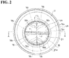
Fig. 2 is a plan view in the state ofFig. 1 . -
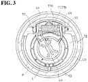
Fig. 3 is a bottom view in the state ofFig 1 . -
Fig. 4 is a cross-sectional view taken along a line A-A inFig. 2 . -
Fig. 5 is an exploded side view of essential parts showing an insertion state of a fuel filling nozzle, wherein a closing member of an upper-side device is in an open position. -
Fig. 6 is an exploded side view of essential parts showing the essential parts of the upper-side device in cross section, wherein an urging device of a flap member of the upper-side device is omitted therein. -
Fig. 7 is a perspective view showing a state wherein a lower-side device is attached to the inlet pipe and the upper-side device is omitted therein. -
Fig. 8 is a plan view of the state ofFig. 7 . -
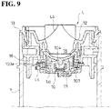
Fig. 9 is a cross-sectional view taken along a line B-B inFig. 8 . -
Fig. 10 is a cross-sectional view of the flap member forming the lower-side device taken along a line C-C inFig. 8 , and shows a projection piece bordering a pass-through opening with imaginary lines. -
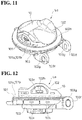
Fig. 11 is a perspective view of the flap member forming the lower-side device. -
Fig. 12 is a side view of the flap member forming the lower-side device. -
Fig. 13 is a plan view of the flap member forming the lower-side device. -
Fig. 14 is a perspective view wherein a seal member forming the lower-side device is viewed from an inlet pipe side. - Hereinafter, based on
Fig. 1 to Fig. 14 , a typical embodiment of the present invention will be explained. An fuel filling aperture opening and closing device according to the present embodiment opens a fuel filling aperture by an insertion of a fuel filling nozzle N to allow the insertion, and automatically closes the fuel filling aperture when the inserted fuel filling nozzle N is pulled out. - Namely, when the fuel filling nozzle N of an fuel filling gun (omitted in the drawings) is inserted into the fuel filling aperture, such fuel filling aperture opening and closing device turns the later-described closing members La and Ua to an open position to allow the insertion of the fuel filling nozzle N forward more than the fuel filling aperture opening and closing device so as to allow fueling, and when the inserted fuel filling nozzle N is pulled out, the fuel filling aperture opening and closing device returns the later-described closing members La and Ua to a closed position to automatically close the fuel filling aperture. Thereby, in such fuel filling aperture opening and closing device, a cap of a screw-type fuel filling aperture is unnecessary.
- In an illustrated example, the fuel filling aperture opening and closing device is attached to an upper end portion Pa forming the fuel filling aperture of an inlet pipe P (a fuel injection pipe) (see
Fig. 4 ). In the illustrated example, in the upper end portion Pa of such inlet pipe P, there are attached two kinds of fuel filling aperture opening and closing devices having different functions. One of such two kinds of fuel filling aperture opening and closing devices is fitted into an inside of the upper end portion Pa of the inlet pipe P (hereinafter, such one fuel filling aperture opening and closing device is called a lower-side device L). In the other of such two kinds of fuel filling aperture opening and closing devices, the lower-side device L is fitted into an outside of the upper end portion Pa of the inlet pipe P from a state fitted into the upper end portion Pa of the inlet pipe P (hereinafter, such other fuel filling aperture opening and closing device is called an upper-side device U). Thereby, the closing member Ua of the upper-side device U is positioned directly above the closing member La of the lower-side device L. When an insertion operation of the fuel filling nozzle N is carried out, the fuel filling nozzle N abuts against the closing member Ua of the upper-side device U to turn the closing member Ua to the open position so as to enter into the fuel filling aperture, and then, abuts against the closing member La of the lower-side device L to turn the closing member La to the open position so as to completely open the fuel filling aperture. - The aforementioned lower-side device L is provided with a cylindrical main member Lb and the closing member La (see
Fig. 7 ). The cylindrical main member Lb opens both of an upper end and a lower end, and has a substantially cylindrical shape. Between the upper end and lower end, an internal space of the cylindrical main member Lb is divided into up and down by apartition wall 12. An outer diameter of the cylindrical main member Lb is substantially equal to an inner diameter of the upper end portion Pa of the inlet pipe P. In the illustrated example, in the upper end of the cylindrical main member Lb, there is formed anouter flange 13, and on an outer face portion of the cylindrical main member Lb, there is formed anengagement projection 14. In the upper end portion Pa of the inlet pipe P, there is formed an engagement hole Pb receiving theengagement projection 14 of the cylindrical main member Lb in a process of fitting the lower-side device L into the upper end portion Pa of the inlet pipe P up to a position where theouter flange 13 abuts against a terminal of the inlet pipe P, and engaged with theengagement projection 14 by an elastic return at a fitting completion position. Also, by the aforementioned engagement, a fitting state of the lower-side device L relative to the inlet pipe P is maintained. In thepartition wall 12, there is formed a circular pass-through opening 15 allowing the fuel filling nozzle N to pass through. In the closed position, the closing member La is pressed against thepartition wall 12 from a lower side to close the pass-throughopening 15, thereby maintaining a closed state of the fuel filling aperture unless the fuel filling nozzle N is inserted (seeFig. 4 ). - On a lower face side of the
partition wall 12, an opening edge portion of the pass-throughopening 15 is bordered by a projection piece 16 (seeFig. 9 ). Namely, in a lower face of thepartition wall 12, there is formed a short cylindrical portion by theprojection piece 16. In the closed position, the closing member La presses a plate-shaped portion 101b (shown inFig. 10 ) of the later-describedseal member 101 against theprojection piece 16 by urging of the later-described urging device 11 (shown inFig. 3 ) to close the pass-through opening 15 in an airtight state. Namely, in the present embodiment, theprojection piece 16 functions as a valve seat. - On the other hand, the closing member La is provided with a
flap member 10 provided with the ring-shaped seal member 101; and the urging device 11 positioning theflap member 10 at the closed position by the urging. - The
flap member 10 is formed by anoutside member 102 and aninside member 103 combined through the seal member 101 (seeFig. 10 to Fig. 12 ). Theoutside member 102 is positioned on a terminal side of the inlet pipe P, and theinside member 103 is positioned on a back side of such inlet pipe P. - The
inside member 103 substantially has a disk shape. On a surface side of theinside member 103, there are formed an insidecircumferential wall 103a; an outsidecircumferential wall 103b surrounding the insidecircumferential wall 103a; and acircumferential groove 103d surrounding the outsidecircumferential wall 103b (seeFig. 10 ). There is formed a circumferentialflat face 103e between thecircumferential groove 103d and an outer edge of theinside member 103. - Also, on a back surface side of the
inside member 103, there is formed a pair of bearingportions Fig. 11 ). The pair of bearingportions inside member 103 to position a protruding end outward more than the outer edge of theinside member 103, and there is provided ashaft hole 103g at the protruding end. Also, in the illustrated example, there is formed a pair of bearingportions partition wall 12 of the cylindrical main member Lb (seeFig. 3 ). In the illustrated example, the pair of bearingportions inside member 103 is housed between the pair of bearingportions shaft hole 103g formed in the pair of bearingportions 103f, so that the closing member La is attached to the cylindrical main member Lb turnably around the shaft member Lc. - The
outside member 102 has a size allowing theflap member 10 to be housed in the pass-throughopening 15 in a state wherein theflap member 10 is in the closed position, and has a circular outline shape (seeFig. 11 ). The fuel filling nozzle N abuts against a surface of theoutside member 102. On a back surface side of theoutside member 102, there is formed acircumferential pinching portion 102a (seeFig. 10 ). Also, in a side portion of theoutside member 102, and on an upper side of thecircumferential pinching portion 102a, there are formedengagement claws 102b protruding outward respectively on both sides in a diametrical direction of theoutside member 102. - In the illustrated example, in a state wherein the
circumferential pinching portion 102a of theoutside member 102 is positioned directly above thecircumferential groove 103d of theinside member 103, and the circumferentialflat face 103e of theinside member 103 is positioned outside an outer edge of theoutside member 102, theengagement claw 102b of theoutside member 102 is engaged with anengagement hole 103c formed in the outsidecircumferential wall 103b of theinside member 103, so that theoutside member 102 and theinside member 103 are integrated. - In the illustrated example, there is formed a
vent hole 103h on an inner side of the insidecircumferential wall 103a of theinside member 103, and there are housed acompression coil spring 105 and avalve member 104 closing thevent hole 103h by urging of theaforementioned spring 105 between theinside member 103 and theoutside member 102, and when a fuel tank side comes to have a high pressure with a predetermined value or above,such valve member 104 rises against the urging of thespring 105 to open thevent hole 103h. Namely, in the illustrated example, theflap member 10 includes a relief valve therein. - On the other hand, the
seal member 101 is provided withseal portions 101a respectively on an inner peripheral portion side and an outer peripheral portion side such that a space S (shown inFig. 10 ) between the inner andouter seal portions such seal member 101 is made of rubber or plastic having rubber-like elasticity. - Also, in
such seal member 101, one of the inner andouter seal portions portion 101b pressed by the urging against theprojection piece 16 bordering the opening edge portion of the pass-throughopening 15 of the fuel filling nozzle N, and the other of the inner andouter seal portions circumferential projecting portion 101c and an outsidecircumferential projecting portion 101d respectively pressed against theflap member 10. - In the present embodiment, an outer diameter of the
seal member 101 is approximately equal to an outer diameter of theinside member 103, and an inner diameter of theseal member 101 is approximately equal to an outer diameter of the outsidecircumferential wall 103b. Then, in the present embodiment, theseal member 101 includes the plate-shapedportion 101b on an outer periphery side thereof, and is provided with the insidecircumferential projecting portion 101c and the outsidecircumferential projecting portion 101d on an inner periphery side thereof. - Specifically, the
seal member 101 has an approximately L shape in cross section including a portion intersecting an axial direction x (seeFig. 4 andFig. 10 ) of the inlet pipe P, and a portion along the axial direction x of the inlet pipe P (seeFig. 10 ), and one portion of the portion intersecting the axial direction is the plate-shapedportion 101b, and the insidecircumferential projecting portion 101c and the outsidecircumferential projecting portion 101d are provided at a terminal of the portion along the axial direction. - In the illustrated example, the
seal member 101 has a structure of forming a circumferentialouter flange 101f which becomes the plate-shapedportion 101b at one cylinder end of ashort cylinder member 101e, and forming acircumferential groove 101g at the other cylinder end of theshort cylinder member 101e, and there are formed the outsidecircumferential projecting portion 101d and the insidecircumferential projecting portion 101c by the other cylinder end of theshort cylinder member 101e divided into the inside and outside by suchcircumferential groove 101g (seeFig. 14 ). - Also, a length L1 (shown in
Fig. 14 ) of theshort cylinder member 101e of theseal member 101 is longer than a distance L2 (shown inFig. 10 ) between thecircumferential pinching portion 102a of theoutside member 102 and a groove bottom of thecircumferential groove 103d of theinside member 103. - In the present embodiment, from a state wherein the
seal member 101 is combined with theinside member 103 such that theshort cylinder member 101e is housed inside thecircumferential groove 103d of theinside member 103, and theouter flange 13 is positioned above the circumferentialflat face 103e, theoutside member 102 is combined with theinside member 103 in the aforementioned manner so as to hold theseal member 101 between such insidemember 103 and outsidemember 102. Thereby, the plate-shapedportion 101b of theseal member 101 is positioned on an outer side of theoutside member 102, and the insidecircumferential projecting portion 101c and the outsidecircumferential projecting portion 101d of theseal member 101 are positioned between theinside member 103 and theoutside member 102. - The inside
circumferential projecting portion 101c of theseal member 101 is pressed against the groove bottom of thecircumferential groove 103d in an elastically deformed state wherein the insidecircumferential projecting portion 101c is narrowed inward, and the outsidecircumferential projecting portion 101d is pressed against the groove bottom of thecircumferential groove 103d in an elastically deformed state wherein the outsidecircumferential projecting portion 101d opens outward, so that the plate-shapedportion 101b is pinched between theprojection piece 16 and the circumferentialflat face 103e in a state wherein the plate-shapedportion 101b is bent such that an upper side becomes a bent inside by the projection piece 16 (Fig 10 ). - In the illustrated example, the urging device 11 is a
torsion coil spring 11a (seeFig. 3 ). In the illustrated example, the shaft member Lc passes through a spring winding portion 11b between the pair of bearingportions inside member 103, and one spring end of thetorsion coil spring 11a wherein the spring winding portion 11b is held abuts against the back surface side of theinside member 103, and the other spring end of thetorsion coil spring 11a abuts against thepartition wall 12 so that an urging force toward the closed position constantly acts on theflap member 10. - Also, in the present embodiment, in the
inside member 103, there is formed acommunication hole 103i communicating the space S between the inner andouter seal portions such communication hole 103i is formed on a groove wall outside thecircumferential groove 103d of the inside member 103 (seeFig. 10 ), thereby providing a state wherein the space S between the plate-shapedportion 101b and the outsidecircumferential projecting portion 101d is communicated with the back side of the inlet pipe P, i.e. the fuel tank side. - When the
flap member 10 forming the closing member La is in the closed position, the plate-shapedportion 101b which becomes one of the inner andouter seal portions seal member 101 is pressed against theprojection piece 16 by the urging, and such urging force concentrates on a relatively narrow pressed portion against theprojection piece 16 so as to highly ensure a sealing performance of the plate-shapedportion 101b. In a case whereinsuch projection piece 16 is not provided, if theseal member 101 swells by fuel, there is a possibility of changing a sealed portion where theseal member 101 contacts relative to the opening edge portion of the aforementioned pass-throughopening 15. However, due to theprojection piece 16, even if the aforementioned swelling and the like occurs, the sealed portion does not change. - Also, the other of the inner and
outer seal portions seal member 101 is formed by the insidecircumferential projecting portion 101c and the outsidecircumferential projecting portion 101d, so that not only when the back side of the inlet pipe P has a high pressure, but also when the outside of the inlet pipe P has a high pressure, one of the insidecircumferential projecting portion 101c and the outsidecircumferential projecting portion 101d, which is positioned on a higher pressure side, is pressed against theflap member 10 by a pressure difference so as to enhance a sealing performance between theseal member 101 and theflap member 10. - In the illustrated example, the
seal member 101 communicates the space S between the inner andouter seal portions circumferential projecting portion 101d is pressed against the groove bottom of thecircumferential groove 103d in the elastically deformed state wherein the outsidecircumferential projecting portion 101d opens outward, and the insidecircumferential projecting portion 101c is pressed against the groove bottom of thecircumferential groove 103d in the elastically deformed state wherein the insidecircumferential projecting portion 101c is narrowed inward (seeFig. 10 ), so that when the back side of the inlet pipe P has the high pressure, due to this pressure, the outsidecircumferential projecting portion 101d is pressed against the flap member 10 (the groove bottom of thecircumferential groove 103d) to enhance the sealing performance between theseal member 101 and theflap member 10. On the contrary, when the outside of the inlet pipe P has the high pressure, due to this pressure, the insidecircumferential projecting portion 101c is pressed against the flap member 10 (the groove bottom of thecircumferential groove 103d) to enhance the sealing performance between theseal member 101 and theflap member 10. - Also, in the present embodiment, the plate-shaped
portion 101b is pinched between theprojection piece 16 and the circumferentialflat face 103e in the state wherein the plate-shapedportion 101b is bent such that the upper side becomes the bent inside by theprojection piece 16, and when the back side of the inlet pipe P has the high pressure, a force shown inFig. 10 with a symbol F acts on a terminal of the plate-shapedportion 101b. Thereby, in the present embodiment, the plate-shapedportion 101b of theseal member 101 is deformed in a direction of enhancing a firmly contacting performance relative to theprojection piece 16 bordering the opening edge portion of the pass-throughopening 15 when the back side of the inlet pipe P has the high pressure. - The aforementioned upper-side device U is provided with a cylindrical main member Ub and the closing member Ua (see
Fig. 1 ). The cylindrical main member Ub opens a lower end, is provided with aninner flange 20 in a circumferential manner at an upper end, and has a form wherein an upper end opening which becomes a pass-throughopening 21 of the fuel filling nozzle N is narrowed by the inner flange 20 (seeFig. 5 ). Namely, such cylindrical main member Ub substantially has a cylindrical shape. An inner diameter of the cylindrical main member Ub is substantially equal to an outer diameter of the upper end portion Pa of the inlet pipe P. In the illustrated example, in an outer face portion of the cylindrical main member Ub, there are formed engagement holes 22 (seeFig. 1 ). In the upper end portion Pa of the inlet pipe P, there are formed engagement projections Pc engaging the engagement holes 22 by an elastic return when the upper-side device U is fitted into the upper end portion Pa of the inlet pipe P by receiving the upper end portion Pa of the inlet pipe P into the cylindrical main member Ub (seeFig. 7 ), and by the aforementioned engagement, a fitting state of the upper-side device U relative to the inlet pipe P is maintained (seeFig. 1 ). In the closed position, the closing member Ua presses theinner flange 20 from a lower side to close the pass-throughopening 21, thereby maintaining the closed state of the fuel filling aperture unless the fuel filling nozzle N is inserted (seeFig. 4 ). - On the other hand, the closing member Ua is provided with a pair of
flap members device 19 positioning eachflap member 18 to the closed position by urging (seeFig. 4 ). - The pair of
flap members assembly portions 18a which become a center of the turning; andabutment portions 18b relative to theother flap member 18 forming the pair, and by the aforementioned urging, the pair offlap members edge portion 21a of the pass-throughopening 21 of the fuel filling nozzle N, and presses theabutment portion 18b against theabutment portion 18b of theother flap member 18 forming the pair. - In the illustrated example, the pass-through
opening 21 has a circular shape. Theflap member 18 respectively has a plate-shaped member with a semicircular shape in a plan view provided with asemi-arc edge portion 18c along an arc for 180 degrees of a virtual circle (omitted in the drawings) wherein an outer diameter thereof is slightly larger than a hole diameter of the pass-throughopening 21; and astraight edge portion 18d dividing the virtual circle along a virtual segment (omitted in the drawings) passing a center of the virtual circle (seeFig. 2 ). The pair offlap members semi-arc edge portion 18c against the openingedge portion 21a of the pass-throughopening 21 from below by the urging, and presses thestraight edge portion 18d of oneflap member 18 against thestraight edge portion 18d of theother flap member 18 so as to close the pass-throughopening 21 together with the other flap member 18 (Fig. 4 ). - In each
flap member 18, there is formed a pair of bearingportions Fig. 6 ). The pair of bearingportions semi-arc edge portion 18c in a direction intersecting thestraight edge portion 18d, and is provided with ashaft hole 18f at a protruding end. Also, in the illustrated example, below theinner flange 20 of the cylindrical main member Ub, there is formed a pair of bearingportions portions flap member 18 is housed between the pair of bearingportions shaft hole 18f formed in the pair of bearingportions flap member 18 is attached to the cylindrical main member Ub turnably around the shaft member Uc. A shaft center line of such shaft member Uc is parallel to thestraight edge portion 18d. - On the other hand, the urging
device 19 is a torsion coil spring 19a wherein onespring end 19b abuts against a support member side of theflap member 18, i.e. the cylindrical main member Ub, and theother spring end 19c abuts against aninclined face 18g formed in a back surface portion of theflap member 18 in a direction of gradually increasing a thickness of theflap member 18 as approaching theabutment portion 18b (seeFig. 4 andFig. 5 ). In the illustrated example, theother spring end 19c, of the torsion coil spring 19a wherein aspring winding portion 19d is held by passing the shaft member Uc through thespring winding portion 19d between the pair of bearingportions flap member 18, abuts against a back surface side of theflap member 18; and onespring end 19b of the torsion coil spring 19a abuts against an inside wall of cylindrical main member Ub, so that an urging force toward the closed position constantly acts on theflap member 18. - Also, in the present embodiment, a portion except for the
semi-arc edge portion 18c of the surface portion of theflap member 18 is formed roughly in a concave shape wherein a portion positioned on a virtual straight line y (shown inFig. 2 ) connecting a middle position in a length direction of thesemi-arc edge portion 18c and a middle position in a length direction of thestraight edge portion 18d is the bottom. Also, corresponding to the shape of the surface portion, a portion except for thesemi-arc edge portion 18c of the back surface portion of theflap member 18 is formed roughly in a convex shape wherein a portion positioned on the virtual straight line y connecting the middle position in the length direction of thesemi-arc edge portion 18c and the middle position in the length direction of thestraight edge portion 18d is the peak. Then, in the illustrated example, in a portion positioned on the virtual straight line in the back surface portion ofsuch flap member 18, there is formed theinclined face 18g. - In the illustrated example, the
inclined face 18g starts from thesemi-arc edge portion 18c, and ends at a middle position in a length direction of the virtual straight line y (seeFig. 4 ). Also, theabutment portion 18b is a vertical face along the axial direction x of the inlet pipe P, and is formed over the whole length of thestraight edge portion 18d. - Also, the
flap member 18 houses the shaft member Uc in theshaft hole 18f provided in the bearingportion 18e of theflap member 18 with room, and is turnably supported in the cylindrical main member Ub as the support member. Namely, an inner diameter of theshaft hole 18f is larger than an outer diameter of the shaft member Uc (seeFig. 6 ). - The
other spring end 19c of the torsion coil spring 19a abuts against theinclined face 18g, so that in theflap member 18 returned to the closed position by receiving an urging force of such spring 19a, there acts a force in a direction of pressing theabutment portion 18b thereof against theabutment portion 18b of theother flap member 18 forming the pair as well. Thereby, in the present embodiment, in the closed position, theabutment portions 18b of the pair offlap members Fig. 4 ). - Also, in the present embodiment, on the back surface portion of the
flap member 18, there are provided guide faces 18h contacting one portion of theother flap member 18 to guide theother flap member 18 to the closed position when there occurs a deviation of timing for returning to the closed position by the urging between the pair offlap members 18 and 18 (seeFig. 5 ). In the illustrated example, on a lower side of theabutment portion 18b, there is formed theguide face 18h inclining in a direction of gradually increasing the thickness of theflap member 18 as separating from theabutment portion 18b over the whole length of thestraight edge portion 18d. In the illustrated example, there are formed the guide faces 18h, and mountain-shapedribs 18i at a corner portion between thestraight edge portion 18d and thesemi-arc edge portion 18c, and one of oblique sides of therib 18i is anextension guide face 18j continuing to theguide face 18h. - Also, in the present embodiment, the surface portion of the
flap member 18 is formed in a concave shape in the aforementioned manner, and on the surface portion, there are formed groove-shapedconcave portions 18k having an arc shape in a cross-sectional shape in a direction parallel to a center axis line of the turning. In the illustrated example, a bottom of such groove-shapedconcave portion 18k is lowered as approaching theabutment portion 18b. Thereby, in the present embodiment, when the fuel filling nozzle N is not inserted in a direction wherein a center axis line of the fuel filling nozzle N to be inserted corresponds to a center axis line of the fuel filling aperture, i.e. a center axis line of the inlet pipe P, a tip of the fuel filling nozzle N is guided to take the aforementioned direction by the aforementioned groove-shapedconcave portion 18k. - Incidentally, obviously, the present invention is not limited to the embodiment explained hereinabove, and includes all embodiments which can obtain the object of the present invention.
-
- N
- an fuel filling nozzle
- La
- a closing member
- 10
- a flap member
- 101
- a seal member
- 101b
- a plate-shaped portion
- 101c
- an inside circumferential projecting portion
- 101d
- an outside circumferential projecting portion
- 11
- an urging device
- 15
- a pass-through opening
- 16
- a projection piece
- Incidentally, all contents of the specification, claims, drawings, and abstract of
Japanese Patent Application No. 2014-082156
Claims (5)
- A fuel filling aperture opening and closing device, comprising:a closing member turned to an open position by an insertion of a fuel filling nozzle to open a fuel filling aperture,wherein the closing member includes a flap member including a ring-shaped seal member, and an urging device urging the flap member to be positioned at a closed position,the seal member includes seal portions respectively inside and outside, and one of the inner and outer seal portions is a plate-shaped portion pressed by urging against a projection piece bordering an opening edge portion of a pass-through opening of the fuel filling nozzle, andthe other of the inner and outer seal portions comprises an inside circumferential projecting portion and an outside circumferential projecting portion respectively pressed against the flap member.
- A fuel filling aperture opening and closing device according to claim 1, wherein the flap member comprises an outside member and an inside member combined through the seal member,
the plate-shaped portion of the seal member is positioned on an outer side of the outside member, and
the inside circumferential projecting portion and outside circumferential projecting portion of the seal member are positioned between the inside member and the outside member. - A fuel filling aperture opening and closing device according to claim 2, wherein the inside member includes a communication hole communicating a space between the inner and outer seal portions to a back side of an inlet pipe.
- A fuel filling aperture opening and closing device according to any one of claims 1 to 3, wherein the seal member has an approximately L shape in cross section including a portion intersecting an axial direction of the inlet pipe, and a portion along the axial direction of the inlet pipe, and one portion of the portion intersecting the axial direction is the plate-shaped portion, and the inside circumferential projecting portion and the outside circumferential projecting portion are provided at a terminal of the portion along the axial direction.
- An fuel filling aperture opening and closing device according to any one of claims 1 to 4, wherein the plate-shaped portion of the seal member is deformed in a direction of enhancing a firmly contacting performance relative to the projection piece bordering the opening edge portion of the pass-through opening when the back side of the inlet pipe has a high pressure.
Applications Claiming Priority (2)
| Application Number | Priority Date | Filing Date | Title |
|---|---|---|---|
| JP2014082156A JP6203106B2 (en) | 2014-04-11 | 2014-04-11 | Oil filler opening and closing device |
| PCT/JP2015/060750 WO2015156252A1 (en) | 2014-04-11 | 2015-04-06 | Oil filler port opening and closing device |
Publications (3)
| Publication Number | Publication Date |
|---|---|
| EP3130498A1 true EP3130498A1 (en) | 2017-02-15 |
| EP3130498A4 EP3130498A4 (en) | 2018-02-28 |
| EP3130498B1 EP3130498B1 (en) | 2019-01-23 |
Family
ID=54287828
Family Applications (1)
| Application Number | Title | Priority Date | Filing Date |
|---|---|---|---|
| EP15777176.7A Active EP3130498B1 (en) | 2014-04-11 | 2015-04-06 | Oil filler port opening and closing device |
Country Status (5)
| Country | Link |
|---|---|
| US (1) | US10322631B2 (en) |
| EP (1) | EP3130498B1 (en) |
| JP (1) | JP6203106B2 (en) |
| CN (1) | CN106414139B (en) |
| WO (1) | WO2015156252A1 (en) |
Cited By (1)
| Publication number | Priority date | Publication date | Assignee | Title |
|---|---|---|---|---|
| US10549630B2 (en) | 2016-02-22 | 2020-02-04 | Yachiyo Industry Co., Ltd. | Erroneous oil feed prevention device |
Families Citing this family (3)
| Publication number | Priority date | Publication date | Assignee | Title |
|---|---|---|---|---|
| JP2017210033A (en) * | 2016-05-23 | 2017-11-30 | ヤマハ発動機株式会社 | Fuel tank |
| CN107161252B (en) * | 2017-05-23 | 2022-04-15 | 力帆实业(集团)股份有限公司 | Motorcycle fuel tank cover installation seal and its assembly structure |
| JP6881339B2 (en) * | 2018-01-31 | 2021-06-02 | 豊田合成株式会社 | Refueling device |
Family Cites Families (23)
| Publication number | Priority date | Publication date | Assignee | Title |
|---|---|---|---|---|
| US3075547A (en) * | 1960-04-22 | 1963-01-29 | Scaramucci Domer | Swing check valve |
| US4825902A (en) * | 1988-01-11 | 1989-05-02 | Halliburton Company | Flapper valve with protective hinge pin sleeve |
| US5466016A (en) * | 1994-04-11 | 1995-11-14 | General Motors Corporation | Solderless filler neck joint |
| EP0970005A4 (en) * | 1997-02-11 | 2000-08-02 | Stant Mfg Co | Seal for filler neck closure assembly |
| DE10004240C2 (en) | 2000-02-01 | 2003-02-27 | Blau Kunststofftechnik Zweigni | Container closure, in particular tank closure |
| FR2827818B1 (en) * | 2001-07-25 | 2003-10-24 | Inergy Automotive Systems Man | BLINDING SYSTEM FOR FUEL TANK FILLING TUBE AND METHOD FOR OPENING SAME |
| JP2003212250A (en) | 2002-01-22 | 2003-07-30 | Toyoda Gosei Co Ltd | Cap device |
| JP4045494B2 (en) * | 2002-12-09 | 2008-02-13 | いすゞ自動車株式会社 | Fuel filler opening structure |
| US6932100B2 (en) * | 2003-05-23 | 2005-08-23 | Eaton Corporation | Flapper type fill tube check valve |
| DE10336776B4 (en) * | 2003-08-08 | 2010-04-08 | Alfmeier Präzision Aktiengesellschaft Baugruppen und Systemlösungen | Filler neck for the fuel tank of a motor vehicle with an automatic tank closure |
| US20050126657A1 (en) | 2003-12-10 | 2005-06-16 | Eaton Corporation | Failed nozzle relief for a mechanically sealed refueling nozzle in a filler tube |
| US6968874B1 (en) | 2004-10-07 | 2005-11-29 | Martinrea Industries, Inc. | Capless automotive fueling system |
| FR2879521B1 (en) * | 2004-12-16 | 2007-03-09 | Inergy Automotive Systems Res | SHUTTERING SYSTEM FOR FUEL TANK FILLING TUBE |
| US7306017B2 (en) * | 2005-01-21 | 2007-12-11 | Eaton Corporation | Capless filler neck assembly for a fuel tank |
| FR2913924B1 (en) * | 2007-03-23 | 2009-06-12 | I T W De France Soc Par Action | HEAD FOR FUEL FILLING TUBE WITH SHUTTER ASSEMBLY. |
| JP4924644B2 (en) | 2009-03-31 | 2012-04-25 | 豊田合成株式会社 | Fuel tank opening and closing device |
| US20100218849A1 (en) * | 2009-02-27 | 2010-09-02 | Toyoda Gosei Co., Ltd. | Fuel tank opening-closing device |
| CN201597438U (en) * | 2009-12-02 | 2010-10-06 | 重庆澳强工贸有限公司 | Ventilated anti-leakage oil tank cover |
| DE102010036970B4 (en) * | 2010-08-12 | 2012-06-06 | Gerdes Gmbh | Lidless filler neck with delayed closing flap |
| JP5406158B2 (en) * | 2010-10-14 | 2014-02-05 | 豊田合成株式会社 | Fuel tank opening and closing device |
| JP5459238B2 (en) * | 2011-01-31 | 2014-04-02 | 豊田合成株式会社 | Fuel tank opening and closing device |
| US8899285B2 (en) | 2011-01-31 | 2014-12-02 | Toyoda Gosei Co., Ltd. | Fuel tank opening and closing device |
| JP2013071683A (en) | 2011-09-28 | 2013-04-22 | Nifco Inc | Fuel filler port device |
-
2014
- 2014-04-11 JP JP2014082156A patent/JP6203106B2/en active Active
-
2015
- 2015-04-06 EP EP15777176.7A patent/EP3130498B1/en active Active
- 2015-04-06 US US15/303,400 patent/US10322631B2/en active Active
- 2015-04-06 CN CN201580028264.0A patent/CN106414139B/en active Active
- 2015-04-06 WO PCT/JP2015/060750 patent/WO2015156252A1/en not_active Ceased
Cited By (1)
| Publication number | Priority date | Publication date | Assignee | Title |
|---|---|---|---|---|
| US10549630B2 (en) | 2016-02-22 | 2020-02-04 | Yachiyo Industry Co., Ltd. | Erroneous oil feed prevention device |
Also Published As
| Publication number | Publication date |
|---|---|
| WO2015156252A1 (en) | 2015-10-15 |
| JP2015202745A (en) | 2015-11-16 |
| EP3130498B1 (en) | 2019-01-23 |
| CN106414139A (en) | 2017-02-15 |
| US10322631B2 (en) | 2019-06-18 |
| US20170036535A1 (en) | 2017-02-09 |
| EP3130498A4 (en) | 2018-02-28 |
| CN106414139B (en) | 2019-11-12 |
| JP6203106B2 (en) | 2017-09-27 |
Similar Documents
| Publication | Publication Date | Title |
|---|---|---|
| EP3130499B1 (en) | Oil filler port opening and closing device | |
| EP3130498B1 (en) | Oil filler port opening and closing device | |
| KR101827688B1 (en) | Fuel tank check valve | |
| CN106537008B (en) | Valve device | |
| CN104203624A (en) | Fuel tank opening and closing device | |
| WO2016031726A1 (en) | Valve case mounting structure | |
| US9784377B2 (en) | Check valve | |
| JP6545088B2 (en) | Motorized valve | |
| US10759271B2 (en) | Fuel filling device | |
| US10500948B2 (en) | Fuel filling device | |
| US9919596B2 (en) | Open-close device for fuel tank | |
| JP2012144128A (en) | Oil feeding part structure of fuel tank | |
| JP2007331518A (en) | Fuel feed pipe | |
| JP3230969U (en) | Compressor seal cap | |
| ES2631606T3 (en) | Piston pump | |
| JP5988675B2 (en) | valve | |
| JP6494456B2 (en) | Governor |
Legal Events
| Date | Code | Title | Description |
|---|---|---|---|
| STAA | Information on the status of an ep patent application or granted ep patent |
Free format text: STATUS: THE INTERNATIONAL PUBLICATION HAS BEEN MADE |
|
| PUAI | Public reference made under article 153(3) epc to a published international application that has entered the european phase |
Free format text: ORIGINAL CODE: 0009012 |
|
| STAA | Information on the status of an ep patent application or granted ep patent |
Free format text: STATUS: REQUEST FOR EXAMINATION WAS MADE |
|
| 17P | Request for examination filed |
Effective date: 20161025 |
|
| AK | Designated contracting states |
Kind code of ref document: A1 Designated state(s): AL AT BE BG CH CY CZ DE DK EE ES FI FR GB GR HR HU IE IS IT LI LT LU LV MC MK MT NL NO PL PT RO RS SE SI SK SM TR |
|
| AX | Request for extension of the european patent |
Extension state: BA ME |
|
| DAV | Request for validation of the european patent (deleted) | ||
| DAX | Request for extension of the european patent (deleted) | ||
| RIC1 | Information provided on ipc code assigned before grant |
Ipc: B60K 15/05 20060101AFI20180118BHEP |
|
| A4 | Supplementary search report drawn up and despatched |
Effective date: 20180126 |
|
| REG | Reference to a national code |
Ref country code: DE Ref legal event code: R079 Ref document number: 602015023726 Country of ref document: DE Free format text: PREVIOUS MAIN CLASS: B60K0015050000 Ipc: B60K0015040000 |
|
| GRAP | Despatch of communication of intention to grant a patent |
Free format text: ORIGINAL CODE: EPIDOSNIGR1 |
|
| STAA | Information on the status of an ep patent application or granted ep patent |
Free format text: STATUS: GRANT OF PATENT IS INTENDED |
|
| RIC1 | Information provided on ipc code assigned before grant |
Ipc: B60K 15/04 20060101AFI20180907BHEP |
|
| INTG | Intention to grant announced |
Effective date: 20181016 |
|
| GRAS | Grant fee paid |
Free format text: ORIGINAL CODE: EPIDOSNIGR3 |
|
| GRAA | (expected) grant |
Free format text: ORIGINAL CODE: 0009210 |
|
| STAA | Information on the status of an ep patent application or granted ep patent |
Free format text: STATUS: THE PATENT HAS BEEN GRANTED |
|
| AK | Designated contracting states |
Kind code of ref document: B1 Designated state(s): AL AT BE BG CH CY CZ DE DK EE ES FI FR GB GR HR HU IE IS IT LI LT LU LV MC MK MT NL NO PL PT RO RS SE SI SK SM TR |
|
| REG | Reference to a national code |
Ref country code: GB Ref legal event code: FG4D |
|
| REG | Reference to a national code |
Ref country code: CH Ref legal event code: EP |
|
| REG | Reference to a national code |
Ref country code: AT Ref legal event code: REF Ref document number: 1091173 Country of ref document: AT Kind code of ref document: T Effective date: 20190215 |
|
| REG | Reference to a national code |
Ref country code: IE Ref legal event code: FG4D |
|
| REG | Reference to a national code |
Ref country code: DE Ref legal event code: R096 Ref document number: 602015023726 Country of ref document: DE |
|
| REG | Reference to a national code |
Ref country code: NL Ref legal event code: MP Effective date: 20190123 |
|
| PG25 | Lapsed in a contracting state [announced via postgrant information from national office to epo] |
Ref country code: NL Free format text: LAPSE BECAUSE OF FAILURE TO SUBMIT A TRANSLATION OF THE DESCRIPTION OR TO PAY THE FEE WITHIN THE PRESCRIBED TIME-LIMIT Effective date: 20190123 |
|
| PG25 | Lapsed in a contracting state [announced via postgrant information from national office to epo] |
Ref country code: PL Free format text: LAPSE BECAUSE OF FAILURE TO SUBMIT A TRANSLATION OF THE DESCRIPTION OR TO PAY THE FEE WITHIN THE PRESCRIBED TIME-LIMIT Effective date: 20190123 Ref country code: LT Free format text: LAPSE BECAUSE OF FAILURE TO SUBMIT A TRANSLATION OF THE DESCRIPTION OR TO PAY THE FEE WITHIN THE PRESCRIBED TIME-LIMIT Effective date: 20190123 Ref country code: ES Free format text: LAPSE BECAUSE OF FAILURE TO SUBMIT A TRANSLATION OF THE DESCRIPTION OR TO PAY THE FEE WITHIN THE PRESCRIBED TIME-LIMIT Effective date: 20190123 Ref country code: NO Free format text: LAPSE BECAUSE OF FAILURE TO SUBMIT A TRANSLATION OF THE DESCRIPTION OR TO PAY THE FEE WITHIN THE PRESCRIBED TIME-LIMIT Effective date: 20190423 Ref country code: FI Free format text: LAPSE BECAUSE OF FAILURE TO SUBMIT A TRANSLATION OF THE DESCRIPTION OR TO PAY THE FEE WITHIN THE PRESCRIBED TIME-LIMIT Effective date: 20190123 Ref country code: PT Free format text: LAPSE BECAUSE OF FAILURE TO SUBMIT A TRANSLATION OF THE DESCRIPTION OR TO PAY THE FEE WITHIN THE PRESCRIBED TIME-LIMIT Effective date: 20190523 Ref country code: SE Free format text: LAPSE BECAUSE OF FAILURE TO SUBMIT A TRANSLATION OF THE DESCRIPTION OR TO PAY THE FEE WITHIN THE PRESCRIBED TIME-LIMIT Effective date: 20190123 |
|
| REG | Reference to a national code |
Ref country code: AT Ref legal event code: MK05 Ref document number: 1091173 Country of ref document: AT Kind code of ref document: T Effective date: 20190123 |
|
| PG25 | Lapsed in a contracting state [announced via postgrant information from national office to epo] |
Ref country code: BG Free format text: LAPSE BECAUSE OF FAILURE TO SUBMIT A TRANSLATION OF THE DESCRIPTION OR TO PAY THE FEE WITHIN THE PRESCRIBED TIME-LIMIT Effective date: 20190423 Ref country code: HR Free format text: LAPSE BECAUSE OF FAILURE TO SUBMIT A TRANSLATION OF THE DESCRIPTION OR TO PAY THE FEE WITHIN THE PRESCRIBED TIME-LIMIT Effective date: 20190123 Ref country code: RS Free format text: LAPSE BECAUSE OF FAILURE TO SUBMIT A TRANSLATION OF THE DESCRIPTION OR TO PAY THE FEE WITHIN THE PRESCRIBED TIME-LIMIT Effective date: 20190123 Ref country code: GR Free format text: LAPSE BECAUSE OF FAILURE TO SUBMIT A TRANSLATION OF THE DESCRIPTION OR TO PAY THE FEE WITHIN THE PRESCRIBED TIME-LIMIT Effective date: 20190424 Ref country code: IS Free format text: LAPSE BECAUSE OF FAILURE TO SUBMIT A TRANSLATION OF THE DESCRIPTION OR TO PAY THE FEE WITHIN THE PRESCRIBED TIME-LIMIT Effective date: 20190523 Ref country code: LV Free format text: LAPSE BECAUSE OF FAILURE TO SUBMIT A TRANSLATION OF THE DESCRIPTION OR TO PAY THE FEE WITHIN THE PRESCRIBED TIME-LIMIT Effective date: 20190123 |
|
| REG | Reference to a national code |
Ref country code: DE Ref legal event code: R097 Ref document number: 602015023726 Country of ref document: DE |
|
| PG25 | Lapsed in a contracting state [announced via postgrant information from national office to epo] |
Ref country code: AL Free format text: LAPSE BECAUSE OF FAILURE TO SUBMIT A TRANSLATION OF THE DESCRIPTION OR TO PAY THE FEE WITHIN THE PRESCRIBED TIME-LIMIT Effective date: 20190123 Ref country code: IT Free format text: LAPSE BECAUSE OF FAILURE TO SUBMIT A TRANSLATION OF THE DESCRIPTION OR TO PAY THE FEE WITHIN THE PRESCRIBED TIME-LIMIT Effective date: 20190123 Ref country code: DK Free format text: LAPSE BECAUSE OF FAILURE TO SUBMIT A TRANSLATION OF THE DESCRIPTION OR TO PAY THE FEE WITHIN THE PRESCRIBED TIME-LIMIT Effective date: 20190123 Ref country code: EE Free format text: LAPSE BECAUSE OF FAILURE TO SUBMIT A TRANSLATION OF THE DESCRIPTION OR TO PAY THE FEE WITHIN THE PRESCRIBED TIME-LIMIT Effective date: 20190123 Ref country code: SK Free format text: LAPSE BECAUSE OF FAILURE TO SUBMIT A TRANSLATION OF THE DESCRIPTION OR TO PAY THE FEE WITHIN THE PRESCRIBED TIME-LIMIT Effective date: 20190123 Ref country code: RO Free format text: LAPSE BECAUSE OF FAILURE TO SUBMIT A TRANSLATION OF THE DESCRIPTION OR TO PAY THE FEE WITHIN THE PRESCRIBED TIME-LIMIT Effective date: 20190123 Ref country code: CZ Free format text: LAPSE BECAUSE OF FAILURE TO SUBMIT A TRANSLATION OF THE DESCRIPTION OR TO PAY THE FEE WITHIN THE PRESCRIBED TIME-LIMIT Effective date: 20190123 |
|
| PG25 | Lapsed in a contracting state [announced via postgrant information from national office to epo] |
Ref country code: SM Free format text: LAPSE BECAUSE OF FAILURE TO SUBMIT A TRANSLATION OF THE DESCRIPTION OR TO PAY THE FEE WITHIN THE PRESCRIBED TIME-LIMIT Effective date: 20190123 |
|
| REG | Reference to a national code |
Ref country code: CH Ref legal event code: PL |
|
| PLBE | No opposition filed within time limit |
Free format text: ORIGINAL CODE: 0009261 |
|
| STAA | Information on the status of an ep patent application or granted ep patent |
Free format text: STATUS: NO OPPOSITION FILED WITHIN TIME LIMIT |
|
| REG | Reference to a national code |
Ref country code: BE Ref legal event code: MM Effective date: 20190430 |
|
| PG25 | Lapsed in a contracting state [announced via postgrant information from national office to epo] |
Ref country code: AT Free format text: LAPSE BECAUSE OF FAILURE TO SUBMIT A TRANSLATION OF THE DESCRIPTION OR TO PAY THE FEE WITHIN THE PRESCRIBED TIME-LIMIT Effective date: 20190123 Ref country code: MC Free format text: LAPSE BECAUSE OF FAILURE TO SUBMIT A TRANSLATION OF THE DESCRIPTION OR TO PAY THE FEE WITHIN THE PRESCRIBED TIME-LIMIT Effective date: 20190123 Ref country code: LU Free format text: LAPSE BECAUSE OF NON-PAYMENT OF DUE FEES Effective date: 20190406 |
|
| 26N | No opposition filed |
Effective date: 20191024 |
|
| PG25 | Lapsed in a contracting state [announced via postgrant information from national office to epo] |
Ref country code: CH Free format text: LAPSE BECAUSE OF NON-PAYMENT OF DUE FEES Effective date: 20190430 Ref country code: LI Free format text: LAPSE BECAUSE OF NON-PAYMENT OF DUE FEES Effective date: 20190430 |
|
| PG25 | Lapsed in a contracting state [announced via postgrant information from national office to epo] |
Ref country code: BE Free format text: LAPSE BECAUSE OF NON-PAYMENT OF DUE FEES Effective date: 20190430 Ref country code: SI Free format text: LAPSE BECAUSE OF FAILURE TO SUBMIT A TRANSLATION OF THE DESCRIPTION OR TO PAY THE FEE WITHIN THE PRESCRIBED TIME-LIMIT Effective date: 20190123 |
|
| PG25 | Lapsed in a contracting state [announced via postgrant information from national office to epo] |
Ref country code: TR Free format text: LAPSE BECAUSE OF FAILURE TO SUBMIT A TRANSLATION OF THE DESCRIPTION OR TO PAY THE FEE WITHIN THE PRESCRIBED TIME-LIMIT Effective date: 20190123 |
|
| PG25 | Lapsed in a contracting state [announced via postgrant information from national office to epo] |
Ref country code: IE Free format text: LAPSE BECAUSE OF NON-PAYMENT OF DUE FEES Effective date: 20190406 |
|
| PG25 | Lapsed in a contracting state [announced via postgrant information from national office to epo] |
Ref country code: CY Free format text: LAPSE BECAUSE OF FAILURE TO SUBMIT A TRANSLATION OF THE DESCRIPTION OR TO PAY THE FEE WITHIN THE PRESCRIBED TIME-LIMIT Effective date: 20190123 |
|
| PG25 | Lapsed in a contracting state [announced via postgrant information from national office to epo] |
Ref country code: HU Free format text: LAPSE BECAUSE OF FAILURE TO SUBMIT A TRANSLATION OF THE DESCRIPTION OR TO PAY THE FEE WITHIN THE PRESCRIBED TIME-LIMIT; INVALID AB INITIO Effective date: 20150406 Ref country code: MT Free format text: LAPSE BECAUSE OF FAILURE TO SUBMIT A TRANSLATION OF THE DESCRIPTION OR TO PAY THE FEE WITHIN THE PRESCRIBED TIME-LIMIT Effective date: 20190123 |
|
| PGFP | Annual fee paid to national office [announced via postgrant information from national office to epo] |
Ref country code: GB Payment date: 20220303 Year of fee payment: 8 |
|
| PG25 | Lapsed in a contracting state [announced via postgrant information from national office to epo] |
Ref country code: MK Free format text: LAPSE BECAUSE OF FAILURE TO SUBMIT A TRANSLATION OF THE DESCRIPTION OR TO PAY THE FEE WITHIN THE PRESCRIBED TIME-LIMIT Effective date: 20190123 |
|
| GBPC | Gb: european patent ceased through non-payment of renewal fee |
Effective date: 20230406 |
|
| PG25 | Lapsed in a contracting state [announced via postgrant information from national office to epo] |
Ref country code: GB Free format text: LAPSE BECAUSE OF NON-PAYMENT OF DUE FEES Effective date: 20230406 |
|
| PG25 | Lapsed in a contracting state [announced via postgrant information from national office to epo] |
Ref country code: GB Free format text: LAPSE BECAUSE OF NON-PAYMENT OF DUE FEES Effective date: 20230406 |
|
| PGFP | Annual fee paid to national office [announced via postgrant information from national office to epo] |
Ref country code: DE Payment date: 20250305 Year of fee payment: 11 |
|
| PGFP | Annual fee paid to national office [announced via postgrant information from national office to epo] |
Ref country code: FR Payment date: 20260309 Year of fee payment: 12 |