EP1515072A1 - Fuel vapor vent valve and method of attaching same to a tank - Google Patents
Fuel vapor vent valve and method of attaching same to a tank Download PDFInfo
- Publication number
- EP1515072A1 EP1515072A1 EP20040020737 EP04020737A EP1515072A1 EP 1515072 A1 EP1515072 A1 EP 1515072A1 EP 20040020737 EP20040020737 EP 20040020737 EP 04020737 A EP04020737 A EP 04020737A EP 1515072 A1 EP1515072 A1 EP 1515072A1
- Authority
- EP
- European Patent Office
- Prior art keywords
- float
- valve
- forming
- tank
- vent
- Prior art date
- Legal status (The legal status is an assumption and is not a legal conclusion. Google has not performed a legal analysis and makes no representation as to the accuracy of the status listed.)
- Granted
Links
Images


Classifications
-
- F—MECHANICAL ENGINEERING; LIGHTING; HEATING; WEAPONS; BLASTING
- F02—COMBUSTION ENGINES; HOT-GAS OR COMBUSTION-PRODUCT ENGINE PLANTS
- F02M—SUPPLYING COMBUSTION ENGINES IN GENERAL WITH COMBUSTIBLE MIXTURES OR CONSTITUENTS THEREOF
- F02M25/00—Engine-pertinent apparatus for adding non-fuel substances or small quantities of secondary fuel to combustion-air, main fuel or fuel-air mixture
- F02M25/08—Engine-pertinent apparatus for adding non-fuel substances or small quantities of secondary fuel to combustion-air, main fuel or fuel-air mixture adding fuel vapours drawn from engine fuel reservoir
-
- F—MECHANICAL ENGINEERING; LIGHTING; HEATING; WEAPONS; BLASTING
- F16—ENGINEERING ELEMENTS AND UNITS; GENERAL MEASURES FOR PRODUCING AND MAINTAINING EFFECTIVE FUNCTIONING OF MACHINES OR INSTALLATIONS; THERMAL INSULATION IN GENERAL
- F16K—VALVES; TAPS; COCKS; ACTUATING-FLOATS; DEVICES FOR VENTING OR AERATING
- F16K24/00—Devices, e.g. valves, for venting or aerating enclosures
- F16K24/04—Devices, e.g. valves, for venting or aerating enclosures for venting only
- F16K24/042—Devices, e.g. valves, for venting or aerating enclosures for venting only actuated by a float
- F16K24/044—Devices, e.g. valves, for venting or aerating enclosures for venting only actuated by a float the float being rigidly connected to the valve element, the assembly of float and valve element following a substantially translational movement when actuated, e.g. also for actuating a pilot valve
-
- Y—GENERAL TAGGING OF NEW TECHNOLOGICAL DEVELOPMENTS; GENERAL TAGGING OF CROSS-SECTIONAL TECHNOLOGIES SPANNING OVER SEVERAL SECTIONS OF THE IPC; TECHNICAL SUBJECTS COVERED BY FORMER USPC CROSS-REFERENCE ART COLLECTIONS [XRACs] AND DIGESTS
- Y10—TECHNICAL SUBJECTS COVERED BY FORMER USPC
- Y10T—TECHNICAL SUBJECTS COVERED BY FORMER US CLASSIFICATION
- Y10T137/00—Fluid handling
- Y10T137/2931—Diverse fluid containing pressure systems
- Y10T137/3003—Fluid separating traps or vents
- Y10T137/3084—Discriminating outlet for gas
- Y10T137/309—Fluid sensing valve
- Y10T137/3099—Float responsive
-
- Y—GENERAL TAGGING OF NEW TECHNOLOGICAL DEVELOPMENTS; GENERAL TAGGING OF CROSS-SECTIONAL TECHNOLOGIES SPANNING OVER SEVERAL SECTIONS OF THE IPC; TECHNICAL SUBJECTS COVERED BY FORMER USPC CROSS-REFERENCE ART COLLECTIONS [XRACs] AND DIGESTS
- Y10—TECHNICAL SUBJECTS COVERED BY FORMER USPC
- Y10T—TECHNICAL SUBJECTS COVERED BY FORMER US CLASSIFICATION
- Y10T137/00—Fluid handling
- Y10T137/7287—Liquid level responsive or maintaining systems
- Y10T137/731—With control fluid connection at desired liquid level
-
- Y—GENERAL TAGGING OF NEW TECHNOLOGICAL DEVELOPMENTS; GENERAL TAGGING OF CROSS-SECTIONAL TECHNOLOGIES SPANNING OVER SEVERAL SECTIONS OF THE IPC; TECHNICAL SUBJECTS COVERED BY FORMER USPC CROSS-REFERENCE ART COLLECTIONS [XRACs] AND DIGESTS
- Y10—TECHNICAL SUBJECTS COVERED BY FORMER USPC
- Y10T—TECHNICAL SUBJECTS COVERED BY FORMER US CLASSIFICATION
- Y10T29/00—Metal working
- Y10T29/49—Method of mechanical manufacture
- Y10T29/494—Fluidic or fluid actuated device making
-
- Y—GENERAL TAGGING OF NEW TECHNOLOGICAL DEVELOPMENTS; GENERAL TAGGING OF CROSS-SECTIONAL TECHNOLOGIES SPANNING OVER SEVERAL SECTIONS OF THE IPC; TECHNICAL SUBJECTS COVERED BY FORMER USPC CROSS-REFERENCE ART COLLECTIONS [XRACs] AND DIGESTS
- Y10—TECHNICAL SUBJECTS COVERED BY FORMER USPC
- Y10T—TECHNICAL SUBJECTS COVERED BY FORMER US CLASSIFICATION
- Y10T29/00—Metal working
- Y10T29/49—Method of mechanical manufacture
- Y10T29/49405—Valve or choke making
- Y10T29/49412—Valve or choke making with assembly, disassembly or composite article making
- Y10T29/49416—Valve or choke making with assembly, disassembly or composite article making with material shaping or cutting
-
- Y—GENERAL TAGGING OF NEW TECHNOLOGICAL DEVELOPMENTS; GENERAL TAGGING OF CROSS-SECTIONAL TECHNOLOGIES SPANNING OVER SEVERAL SECTIONS OF THE IPC; TECHNICAL SUBJECTS COVERED BY FORMER USPC CROSS-REFERENCE ART COLLECTIONS [XRACs] AND DIGESTS
- Y10—TECHNICAL SUBJECTS COVERED BY FORMER USPC
- Y10T—TECHNICAL SUBJECTS COVERED BY FORMER US CLASSIFICATION
- Y10T29/00—Metal working
- Y10T29/49—Method of mechanical manufacture
- Y10T29/49405—Valve or choke making
- Y10T29/49426—Valve or choke making including metal shaping and diverse operation
-
- Y—GENERAL TAGGING OF NEW TECHNOLOGICAL DEVELOPMENTS; GENERAL TAGGING OF CROSS-SECTIONAL TECHNOLOGIES SPANNING OVER SEVERAL SECTIONS OF THE IPC; TECHNICAL SUBJECTS COVERED BY FORMER USPC CROSS-REFERENCE ART COLLECTIONS [XRACs] AND DIGESTS
- Y10—TECHNICAL SUBJECTS COVERED BY FORMER USPC
- Y10T—TECHNICAL SUBJECTS COVERED BY FORMER US CLASSIFICATION
- Y10T29/00—Metal working
- Y10T29/49—Method of mechanical manufacture
- Y10T29/49826—Assembling or joining
- Y10T29/4984—Retaining clearance for motion between assembled parts
-
- Y—GENERAL TAGGING OF NEW TECHNOLOGICAL DEVELOPMENTS; GENERAL TAGGING OF CROSS-SECTIONAL TECHNOLOGIES SPANNING OVER SEVERAL SECTIONS OF THE IPC; TECHNICAL SUBJECTS COVERED BY FORMER USPC CROSS-REFERENCE ART COLLECTIONS [XRACs] AND DIGESTS
- Y10—TECHNICAL SUBJECTS COVERED BY FORMER USPC
- Y10T—TECHNICAL SUBJECTS COVERED BY FORMER US CLASSIFICATION
- Y10T29/00—Metal working
- Y10T29/49—Method of mechanical manufacture
- Y10T29/49826—Assembling or joining
- Y10T29/49904—Assembling a subassembly, then assembling with a second subassembly
Definitions
- the present invention relates to fuel vapor vent valves employed in vapor emission controls systems in motor vehicle fuel tank installations.
- the invention particularly relates to float operated vent valves attached to the upper wall of a non-metallic fuel tank.
- Valves employed for such applications are commonly mounted onto the tank through an access opening formed in the upper wall with portions of the valve extending outwardly over the opening and attached to the outer surface of the tank in a sealing arrangement, as for example, by weldment of compatible non-metallic material to the surface of the tank.
- the present invention provides a float operated vapor vent valve for a fuel tank which may be assembled through an access opening formed in the upper wall of the tank with the float operated valve extending interiorly of the tank and a vent port connection extending exteriorly of the tank.
- the valve has a flange formed of material compatible for welding to the outer surface of the tank to effect a permanent sealing attachment thereon.
- the float is slidably movable in the float chamber and has surfaces thereon engaging the wall of the float chamber to prevent relative rotation of the float valve member with respect to the valve body.
- the slidable rotary float constraint enables spin welding of the flange to the tank without loss of calibration or damage to the valve components.
- An optional gravity operated pressure relief valve may be incorporated in the vent passage; and, the relief valve also has surfaces thereon slidably engaging the wall of the vent passage to prevent relative rotation of the relief valve poppet during spin welding.
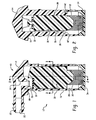
- FIG. 1 is a cross section of a valve employing the present invention
- FIG. 2 is a sectional view taken along section indicating line 2-2 of FIG. 1;
- FIG. 3 is a section view taken along section indicating line 3-3 of FIG. 1;
- FIG. 4 is a cross section of an alternate embodiment of the invention shown mounted through an access opening in a fuel tank;
- FIG. 5 is a section view taken along section indicating line 5-5 of FIG. 4;
- FIG. 6 is a section view taken along section indicating line 6-6 of FIG. 4.
- a valve assembly indicated generally at 10 has a unitary or one piece body indicated generally at 12, formed with an upper or exterior portion 14 with an annular mounting flange 18 and a lower portion 16 intended for extending interiorly of the tank.
- the upper portion has a fitting 20 provided thereon with a vent passage 22 formed therein; and, fitting 20 is adapted for having a flexible hose received thereon for connection thereto.
- Passage 22 communicates with a downwardly extending passage 24 which has a valve seat 26 formed at the lower end thereof.
- the lower portion 16 of the body has a float chamber 28 formed therein into which is received a float member 30 with a resiliently flexible valve member in the form of a pivoted flapper pad or disk 32 disposed on the upper end of the float 30 for movement therewith.
- the float 30 is biased upwardly by a spring 32 with one end registered against the lower end of the float 30 and the opposite end of the spring 32 registered against an end cap or closure member 34 secured in the lower end of the float chamber 28.
- the spring is calibrated to provide the desired buoyancy force in the fuel to be used in a known manner. It will be understood that when the fuel level in the tank rises to a certain level, upward movement of float 30 causes valve member 32 to close against valve seat 26.
- the float 30 has at least one and preferably a plurality of oppositely disposed engagement surfaces in the form of longitudinal groves 36, 38 formed therein; and, the wall of the float chamber 28 has correspondingly configured engagement surfaces in the form of projections 40, 42 provided thereon which slidably engage the groves 36, 38 respectively.
- the sliding engagement of the projections 40, 42 with the grooves 36, 38 prevents relative rotation of the float with respect to the body and thus prevents damage to the float and valve member and any deleterious effects on the calibration of the float spring 32.
- FIGS. 4, 5 and 6 another embodiment of the invention indicated generally at 50 is illustrated and includes a body 52 having a float chamber 54 formed therein with a float assembly indicated generally at 56 slidably received therein and retained by a cap or closure 58 attached to the lower end of the body.
- the float assembly 56 includes a resilient valve member 60 disposed and captured on the upper end of the float 56.
- the upper end of the body is attached to a cover member 62 which is disposed exteriorly of the wall of a fuel tank 64 with portions thereof extending through an access opening 66 formed in the tank wall 64.
- the cover 62 has an annular flange 68 extending outwardly of the access opening 66 and which is retained and sealed on the outer surface of the tank wall 64 by spin welding.
- vent passage 70 having a valve seat 72 associated therewith which is disposed vertically in line with the valve member 60, and, valve seat 72 is closed by valve member 60 upon upward movement of the float when the fuel level rises to a level causing the float to close the valve.
- Vent passage 70 communicates with an upward passage 74 which communicates with a vent outlet 76 formed in a fitting 78 adapted for receiving an end of a hose thereover.
- the body 52 is attached to the cover 62 by snap locking of barbs 80 into apertures or recesses 81 formed in the cylindrical portion 82 of the cover which extends downwardly through the access opening 66.
- the upper end of the body 52 is attached and secured to the cover by a labyrinth seal indicated generally at 84; and, the assembly of the body 52 and the cover 62 is attached to the upper surface of the tank 64 by spin welding.
- the float assembly 56 has at least one and preferably a plurality of engagement surfaces in the form of longitudinally extending grooves 84 formed therein which are slidably engaged with a correspondingly disposed pair of engagement surfaces or guides 86 formed on the inner periphery of float chamber 54.
- a gravity operated pressure relief valve member 88 is slidably disposed in the passage 75 formed as a counter bore on the upper end of vent passage 70, with a valving surface 90 formed on the lower end thereof for seating against the upper end of the vent passage 70.
- the valve member 88 has a plurality of projections or engagement surfaces 92, 94, preferably formed by cross pins, which are slidably received in the slot 96 formed in the upper end of the body 52. The engagement of pins 92, 94 with the slot 96 prevents rotation of the valve member 88 during spin welding.
- the present invention thus provides for spin welding attachment of a fuel vapor vent valve to the exterior surface of a fuel tank which eliminates the need for a heating device for welding.
- the invention permits spin welding without disturbing the interior components and calibration of the vapor vent valve during spinning.
- the valve of the present invention includes surfaces on the float and on an optional gravity pressure relief valve which slidably engage corresponding surfaces on the valve body to prevent relative rotation of the respective parts during the spin welding operation.
Abstract
Description
- The present invention relates to fuel vapor vent valves employed in vapor emission controls systems in motor vehicle fuel tank installations. The invention particularly relates to float operated vent valves attached to the upper wall of a non-metallic fuel tank. Valves employed for such applications are commonly mounted onto the tank through an access opening formed in the upper wall with portions of the valve extending outwardly over the opening and attached to the outer surface of the tank in a sealing arrangement, as for example, by weldment of compatible non-metallic material to the surface of the tank.
- Heretofore the weldment has been by hot-plate or sonic welding techniques which have proven relatively costly in mass production. Heretofore, attempts to spin weld a fuel vapor vent valve of the present type have resulted in destruction of the valving surfaces by the extreme rotational accelerations and decelerations. Furthermore, proper or accurate orientation of the vent hose connector was not possible with spin welding. However, spin welding has been desired as a more cost effective way of attaching the vent valve to the tank than hot-late or sonic welding.
- The present invention provides a float operated vapor vent valve for a fuel tank which may be assembled through an access opening formed in the upper wall of the tank with the float operated valve extending interiorly of the tank and a vent port connection extending exteriorly of the tank. The valve has a flange formed of material compatible for welding to the outer surface of the tank to effect a permanent sealing attachment thereon. The float is slidably movable in the float chamber and has surfaces thereon engaging the wall of the float chamber to prevent relative rotation of the float valve member with respect to the valve body. The slidable rotary float constraint enables spin welding of the flange to the tank without loss of calibration or damage to the valve components. An optional gravity operated pressure relief valve may be incorporated in the vent passage; and, the relief valve also has surfaces thereon slidably engaging the wall of the vent passage to prevent relative rotation of the relief valve poppet during spin welding.
- FIG. 1 is a cross section of a valve employing the present invention;
- FIG. 2 is a sectional view taken along section indicating line 2-2 of FIG. 1;
- FIG. 3 is a section view taken along section indicating line 3-3 of FIG. 1;
- FIG. 4 is a cross section of an alternate embodiment of the invention shown mounted through an access opening in a fuel tank;
- FIG. 5 is a section view taken along section indicating line 5-5 of FIG. 4; and
- FIG. 6 is a section view taken along section indicating line 6-6 of FIG. 4.
- Referring to FIG. 1, a valve assembly indicated generally at 10 has a unitary or one piece body indicated generally at 12, formed with an upper or
exterior portion 14 with anannular mounting flange 18 and alower portion 16 intended for extending interiorly of the tank. The upper portion has afitting 20 provided thereon with avent passage 22 formed therein; and, fitting 20 is adapted for having a flexible hose received thereon for connection thereto.Passage 22 communicates with a downwardly extendingpassage 24 which has avalve seat 26 formed at the lower end thereof. - The
lower portion 16 of the body has afloat chamber 28 formed therein into which is received afloat member 30 with a resiliently flexible valve member in the form of a pivoted flapper pad ordisk 32 disposed on the upper end of thefloat 30 for movement therewith. - The
float 30 is biased upwardly by aspring 32 with one end registered against the lower end of thefloat 30 and the opposite end of thespring 32 registered against an end cap orclosure member 34 secured in the lower end of thefloat chamber 28. The spring is calibrated to provide the desired buoyancy force in the fuel to be used in a known manner. It will be understood that when the fuel level in the tank rises to a certain level, upward movement offloat 30 causesvalve member 32 to close againstvalve seat 26. - Referring to FIGS. 2 and 3, the
float 30 has at least one and preferably a plurality of oppositely disposed engagement surfaces in the form oflongitudinal groves float chamber 28 has correspondingly configured engagement surfaces in the form ofprojections groves body flange 18 onto the fuel tank the sliding engagement of theprojections grooves float spring 32. - Referring to FIGS. 4, 5 and 6, another embodiment of the invention indicated generally at 50 is illustrated and includes a
body 52 having afloat chamber 54 formed therein with a float assembly indicated generally at 56 slidably received therein and retained by a cap orclosure 58 attached to the lower end of the body. Thefloat assembly 56 includes aresilient valve member 60 disposed and captured on the upper end of thefloat 56. - The upper end of the body is attached to a
cover member 62 which is disposed exteriorly of the wall of afuel tank 64 with portions thereof extending through an access opening 66 formed in thetank wall 64. Thecover 62 has anannular flange 68 extending outwardly of the access opening 66 and which is retained and sealed on the outer surface of thetank wall 64 by spin welding. - The upper end of the body defines a
vent passage 70 having avalve seat 72 associated therewith which is disposed vertically in line with thevalve member 60, and,valve seat 72 is closed byvalve member 60 upon upward movement of the float when the fuel level rises to a level causing the float to close the valve.Vent passage 70 communicates with an upward passage 74 which communicates with avent outlet 76 formed in afitting 78 adapted for receiving an end of a hose thereover. - The
body 52 is attached to thecover 62 by snap locking ofbarbs 80 into apertures or recesses 81 formed in thecylindrical portion 82 of the cover which extends downwardly through the access opening 66. - The upper end of the
body 52 is attached and secured to the cover by a labyrinth seal indicated generally at 84; and, the assembly of thebody 52 and thecover 62 is attached to the upper surface of thetank 64 by spin welding. - Referring to FIG. 5, the
float assembly 56 has at least one and preferably a plurality of engagement surfaces in the form of longitudinally extendinggrooves 84 formed therein which are slidably engaged with a correspondingly disposed pair of engagement surfaces orguides 86 formed on the inner periphery offloat chamber 54. - Referring to FIGS. 4 and 6, a gravity operated pressure
relief valve member 88 is slidably disposed in the passage 75 formed as a counter bore on the upper end ofvent passage 70, with a valving surface 90 formed on the lower end thereof for seating against the upper end of thevent passage 70. Thevalve member 88 has a plurality of projections orengagement surfaces slot 96 formed in the upper end of thebody 52. The engagement ofpins slot 96 prevents rotation of thevalve member 88 during spin welding. - The present invention thus provides for spin welding attachment of a fuel vapor vent valve to the exterior surface of a fuel tank which eliminates the need for a heating device for welding. The invention permits spin welding without disturbing the interior components and calibration of the vapor vent valve during spinning. The valve of the present invention includes surfaces on the float and on an optional gravity pressure relief valve which slidably engage corresponding surfaces on the valve body to prevent relative rotation of the respective parts during the spin welding operation.
- Although the invention has hereinabove been described with respect to the illustrated embodiments, it will be understood that the invention is capable of modification and variation and is limited only by the following claims.
Claims (18)
- A method of mounting a float operated vapor vent valve through an access opening to a fuel tank comprising:(a) forming a valve body (12) with a flange (18, 68) of weldable material and having a float chamber (28, 54) and disposing a float (30, 56) therein and forming a vent port (24, 74) with a float valve (26, 60) communicating with the float chamber;(b) disposing a valve member (26) for movement with the float and moving the float and seating the valve member on said valve seat and closing the vent port;(c) forming co-operating surfaces (18, 86) on said float chamber (36, 84) and said float and slidably engaging said surfaces and preventing relative rotation therebetween;(d) inserting portions of said body through an access hole (66) in the tank; and,(e) spin welding said flange to the tank.
- The method defined in claim 1, wherein said step of forming a body includes forming an annular flange (62) extending outwardly over said access opening.
- The method defined in claim 2 wherein said step of slidably restraining includes forming a pair of oppositely disposed slots (96) and forming projections (92, 94) on the valve member and disposing the projections in said slot.
- The method defined in claim 1 wherein said step of forming cooperating surfaces on said body chamber and said float includes forming a plurality of ribs on one of said chambers and said float and forming corresponding grooves on the other.
- The method defined in claim 1, further comprising disposing a gravity operated pressure relief valve (88) in said vent port downstream of said float valve seat.
- The method defined in claim 5 wherein said step of disposing a pressure relief valve includes slidably disposing an obturator and preventing rotation thereof with respect to said body.
- The method defined in claim 6 wherein said step of preventing rotation includes forming a plurality of slots and engaging the slots with cooperating surfaces on said obturator.
- The method defined in claim 7 wherein said step of engaging the slots includes disposing a cross pin in said pressure relief valve.
- The method defined in claim 1, wherein said step of forming a valve body includes forming a body of non-weldable material and attaching a cover of weldable material with the flange portion thereon.
- A float operated vapor vent valve for mounting through an access opening in a fuel tank and weldment to the tank:(a) a valve body (12, 50) formed of material with a flange portion (18, 62)weldable to the tank and having a valving cavity (28, 80) therein with a vent passage having a valve seat;(b) a float (30, 56) disposed in the valving cavity and having a valve member (26, 60) thereon moveable with the float for closing against said valve seat;(c) said flange portion extends outwardly over the access opening and is spin welded to the tank; and,(d) said float includes surfaces (84) thereon engaging cooperating surfaces (18, 86) in said valving chamber for preventing relative rotation therebetween during spin welding.
- The combination defined in claim 10, wherein said cooperating surfaces include ribs on one of said float and valving chamber and grooves on the other.
- The combination defined in claim 10, further comprising a gravity operated pressure relief valve (88) disposed in said vent chamber downstream of said vent valve seat.
- The combination defined in claim 12, wherein said pressure relief valve includes another valve seat (70) and an obturator (88) moveable with respect thereto.
- The combination defined in claim 12, wherein said pressure relief valve includes another valve seat and an obturator moveable with respect thereto and anti-spin means (92, 94, 96) operable to prevent relative rotation between said obturator and said another valve seat during spin welding.
- The combination defined in claim 14, wherein said anti-spin means includes a slot (96) in said body slidably engaged by a projection (92, 94) on said obturator.
- The combustion defined in claim 15, wherein projection includes a cross pin (92, 94) in said obturator.
- The combination defined in claim 10, wherein said cover seal on said body includes an annular labyrinth seal (84).
- The combination defined in claim 10, wherein said body is formed of non-weldable material and has a cover of weldable material with said flange attached thereto.
Applications Claiming Priority (2)
| Application Number | Priority Date | Filing Date | Title |
|---|---|---|---|
| US10/662,579 US7146729B2 (en) | 2003-09-15 | 2003-09-15 | Fuel vapor vent valve and method of attaching same to a tank |
| US662579 | 2003-09-15 |
Publications (2)
| Publication Number | Publication Date |
|---|---|
| EP1515072A1 true EP1515072A1 (en) | 2005-03-16 |
| EP1515072B1 EP1515072B1 (en) | 2007-10-24 |
Family
ID=34136807
Family Applications (1)
| Application Number | Title | Priority Date | Filing Date |
|---|---|---|---|
| EP20040020737 Expired - Fee Related EP1515072B1 (en) | 2003-09-15 | 2004-09-01 | Fuel vapor vent valve and method of attaching same to a tank |
Country Status (8)
| Country | Link |
|---|---|
| US (1) | US7146729B2 (en) |
| EP (1) | EP1515072B1 (en) |
| JP (1) | JP4618541B2 (en) |
| KR (1) | KR20050027933A (en) |
| AU (1) | AU2004203821B2 (en) |
| CA (1) | CA2481985A1 (en) |
| DE (1) | DE602004009648T2 (en) |
| TW (1) | TW200524725A (en) |
Cited By (1)
| Publication number | Priority date | Publication date | Assignee | Title |
|---|---|---|---|---|
| US7146729B2 (en) * | 2003-09-15 | 2006-12-12 | Eaton Corporation | Fuel vapor vent valve and method of attaching same to a tank |
Families Citing this family (10)
| Publication number | Priority date | Publication date | Assignee | Title |
|---|---|---|---|---|
| JP4603949B2 (en) * | 2005-07-29 | 2010-12-22 | 豊田合成株式会社 | Fuel shut-off valve |
| US20070265161A1 (en) * | 2006-05-11 | 2007-11-15 | Gadkaree Kishor P | Activated carbon honeycomb catalyst beds and methods for the manufacture of same |
| US20080257426A1 (en) * | 2007-04-19 | 2008-10-23 | Spink Kenneth M | Integral hinge |
| DE102008045156A1 (en) | 2008-08-30 | 2010-03-04 | Ab Elektronik Gmbh | Measuring device for determining fluid filling level in fuel tank of vehicle, has floating body contacting surface of wall at positions that are provided in predetermined partial region, and corner region covered by partial region |
| EP2872348B1 (en) | 2012-07-12 | 2020-01-15 | Eaton Corporation | Flapper valve with guide legs |
| WO2014105453A2 (en) * | 2012-12-24 | 2014-07-03 | Eaton Corporation | Valve assembly for a tank of a vehicle |
| DE202013012312U1 (en) | 2013-11-12 | 2016-02-24 | Veritas Ag | vent valve |
| US10060544B2 (en) | 2016-02-29 | 2018-08-28 | Ford Global Technologies, Llc | Noise attenuated fill limit vent valve |
| GB2608013B (en) * | 2019-12-24 | 2023-12-13 | Piolax Inc | Valve device |
| CN112339280B (en) * | 2020-10-23 | 2022-09-02 | 河北华盾管道制造有限公司 | High density polyethylene pipe fitting tubular product splicing apparatus |
Citations (3)
| Publication number | Priority date | Publication date | Assignee | Title |
|---|---|---|---|---|
| US5404907A (en) * | 1993-02-18 | 1995-04-11 | G. T. Products, Inc. | Weldable vapor vent valve for fuel tanks |
| US6025086A (en) * | 1997-07-07 | 2000-02-15 | Optima Batteries, Inc. | Battery vent mechanism and method |
| US6206057B1 (en) * | 1994-08-24 | 2001-03-27 | G. T. Products, Inc. | Two-stage ORVR control valve |
Family Cites Families (25)
| Publication number | Priority date | Publication date | Assignee | Title |
|---|---|---|---|---|
| US4719681A (en) * | 1985-07-08 | 1988-01-19 | Futurecraft Corporation | Method of making a fluid flow controlling slide member for a valve body |
| US5062444A (en) * | 1989-10-10 | 1991-11-05 | G. T. Products, Inc. | Fuel level responsive vapor vent valve |
| JPH06147045A (en) * | 1992-10-30 | 1994-05-27 | Toyoda Gosei Co Ltd | Fuel cutoff device |
| US5313977A (en) * | 1992-11-12 | 1994-05-24 | G. T. Products, Inc. | Fluid-responsive vent control valve with peel-away opening action |
| JP2853572B2 (en) * | 1994-04-28 | 1999-02-03 | 豊田合成株式会社 | Two-way valve and fuel shut-off device |
| US5640989A (en) * | 1995-01-12 | 1997-06-24 | Nok Corporation | Fuel cut-off valve |
| US5605175A (en) * | 1995-05-24 | 1997-02-25 | Bergsma; Rudolph | Fluid responsive vent control valve with peel-away opening action |
| US5906224A (en) * | 1996-04-22 | 1999-05-25 | Dapco Industries | Reserve fuel valve and method for making |
| US5954091A (en) * | 1997-07-30 | 1999-09-21 | G.T. Products, Inc. | Retaining structure for a fuel tank mounted valve body |
| US5996607A (en) * | 1998-04-15 | 1999-12-07 | Eaton Corporation | Installing a fill limiting vent valve in a fuel tank |
| JP3506034B2 (en) * | 1999-03-15 | 2004-03-15 | 豊田合成株式会社 | Fuel shutoff valve |
| IL131051A0 (en) * | 1999-07-23 | 2001-01-28 | Raviv Prec Injection Molding | Valve and method for fitting it to a tank |
| CA2334149C (en) * | 2000-02-03 | 2005-05-10 | Stant Manufacturing Inc. | Weldable mount for fuel systems component |
| JP2001323854A (en) * | 2000-03-09 | 2001-11-22 | Toyoda Gosei Co Ltd | Fuel cutoff valve and method of manufacturing the same |
| JP3994662B2 (en) * | 2000-03-30 | 2007-10-24 | 豊田合成株式会社 | Fuel shut-off valve |
| JP2001329925A (en) * | 2000-05-23 | 2001-11-30 | Aisan Ind Co Ltd | Fuel cut-off valve device |
| JP3893987B2 (en) * | 2001-03-16 | 2007-03-14 | 東海ゴム工業株式会社 | Molding method for tank joint parts and ring-shaped resin moldings |
| US6584996B2 (en) * | 2001-07-17 | 2003-07-01 | Eaton Corporation | Installing a valve in a tank |
| US6691725B2 (en) * | 2001-12-14 | 2004-02-17 | Eaton Corporation | Fuel vapor vent valve with peel-off mechanism for ensuring reopening |
| US6848463B2 (en) * | 2003-02-05 | 2005-02-01 | Ti Group Automotive Systems, L.L.C. | Vapor vent valve |
| JP4317397B2 (en) * | 2003-07-10 | 2009-08-19 | 株式会社パイオラックス | Method for manufacturing float valve device |
| US6863082B1 (en) * | 2003-08-13 | 2005-03-08 | Eaton Corporation | Mounting a fuel vapor management valve internally to a gas tank |
| US7146729B2 (en) * | 2003-09-15 | 2006-12-12 | Eaton Corporation | Fuel vapor vent valve and method of attaching same to a tank |
| US20050145316A1 (en) * | 2004-01-05 | 2005-07-07 | Eaton Corporation | Attaching dissimilar materials to a fuel tank by weldment |
| JP2006234159A (en) * | 2004-11-24 | 2006-09-07 | Toyoda Gosei Co Ltd | Fuel cutoff valve |
-
2003
- 2003-09-15 US US10/662,579 patent/US7146729B2/en not_active Expired - Fee Related
-
2004
- 2004-08-10 AU AU2004203821A patent/AU2004203821B2/en not_active Ceased
- 2004-09-01 DE DE200460009648 patent/DE602004009648T2/en active Active
- 2004-09-01 EP EP20040020737 patent/EP1515072B1/en not_active Expired - Fee Related
- 2004-09-06 TW TW93126863A patent/TW200524725A/en unknown
- 2004-09-07 JP JP2004259910A patent/JP4618541B2/en not_active Expired - Fee Related
- 2004-09-14 KR KR1020040073447A patent/KR20050027933A/en active IP Right Grant
- 2004-09-15 CA CA 2481985 patent/CA2481985A1/en not_active Abandoned
Patent Citations (3)
| Publication number | Priority date | Publication date | Assignee | Title |
|---|---|---|---|---|
| US5404907A (en) * | 1993-02-18 | 1995-04-11 | G. T. Products, Inc. | Weldable vapor vent valve for fuel tanks |
| US6206057B1 (en) * | 1994-08-24 | 2001-03-27 | G. T. Products, Inc. | Two-stage ORVR control valve |
| US6025086A (en) * | 1997-07-07 | 2000-02-15 | Optima Batteries, Inc. | Battery vent mechanism and method |
Cited By (1)
| Publication number | Priority date | Publication date | Assignee | Title |
|---|---|---|---|---|
| US7146729B2 (en) * | 2003-09-15 | 2006-12-12 | Eaton Corporation | Fuel vapor vent valve and method of attaching same to a tank |
Also Published As
| Publication number | Publication date |
|---|---|
| KR20050027933A (en) | 2005-03-21 |
| JP4618541B2 (en) | 2011-01-26 |
| DE602004009648T2 (en) | 2008-08-28 |
| CA2481985A1 (en) | 2005-03-15 |
| AU2004203821B2 (en) | 2011-05-12 |
| AU2004203821A1 (en) | 2005-04-07 |
| EP1515072B1 (en) | 2007-10-24 |
| US20050055817A1 (en) | 2005-03-17 |
| US7146729B2 (en) | 2006-12-12 |
| JP2005090504A (en) | 2005-04-07 |
| TW200524725A (en) | 2005-08-01 |
| DE602004009648D1 (en) | 2007-12-06 |
Similar Documents
| Publication | Publication Date | Title |
|---|---|---|
| EP1617113B1 (en) | Fuel vapor vent valve float assembly and method of making same | |
| US5960816A (en) | Adjustable length vent valve system for fuel tanks | |
| EP1705051B1 (en) | Low profile overfill limit device with reverse flow capability | |
| US5996607A (en) | Installing a fill limiting vent valve in a fuel tank | |
| US7146729B2 (en) | Fuel vapor vent valve and method of attaching same to a tank | |
| KR20030085500A (en) | Siphonable check valve and method of making same | |
| JP2005133875A (en) | Check valve integrated cutoff valve | |
| EP1221566A1 (en) | Noise dampened float type fuel vapor vent valve | |
| US5775362A (en) | Fuel-effusion prevention valve | |
| US11009147B2 (en) | Valve device for fuel tank | |
| JP2001329925A (en) | Fuel cut-off valve device | |
| EP1504944A1 (en) | Siphonable poppet-type fill tube check valve | |
| EP1406780B1 (en) | Installing a valve in a tank | |
| US7757880B2 (en) | Tank cap | |
| US10953742B2 (en) | Fuel tank | |
| CN114599905A (en) | Valve device | |
| JP4470156B2 (en) | Closure / retainer assembly with no directivity in the direction of rotation and valve assembly used | |
| JP2564542Y2 (en) | Valve device | |
| JPH0516680A (en) | Valve structure for fuel tank | |
| JPH0622041U (en) | Fuel cutoff valve | |
| JP2011016478A (en) | Fuel cut-off valve |
Legal Events
| Date | Code | Title | Description |
|---|---|---|---|
| PUAI | Public reference made under article 153(3) epc to a published international application that has entered the european phase |
Free format text: ORIGINAL CODE: 0009012 |
|
| AK | Designated contracting states |
Kind code of ref document: A1 Designated state(s): AT BE BG CH CY CZ DE DK EE ES FI FR GB GR HU IE IT LI LU MC NL PL PT RO SE SI SK TR |
|
| AX | Request for extension of the european patent |
Extension state: AL HR LT LV MK |
|
| 17P | Request for examination filed |
Effective date: 20050903 |
|
| AKX | Designation fees paid |
Designated state(s): DE ES FR GB IT SE |
|
| GRAP | Despatch of communication of intention to grant a patent |
Free format text: ORIGINAL CODE: EPIDOSNIGR1 |
|
| GRAS | Grant fee paid |
Free format text: ORIGINAL CODE: EPIDOSNIGR3 |
|
| GRAA | (expected) grant |
Free format text: ORIGINAL CODE: 0009210 |
|
| AK | Designated contracting states |
Kind code of ref document: B1 Designated state(s): DE ES FR GB IT SE |
|
| REG | Reference to a national code |
Ref country code: GB Ref legal event code: FG4D |
|
| REF | Corresponds to: |
Ref document number: 602004009648 Country of ref document: DE Date of ref document: 20071206 Kind code of ref document: P |
|
| PG25 | Lapsed in a contracting state [announced via postgrant information from national office to epo] |
Ref country code: SE Free format text: LAPSE BECAUSE OF FAILURE TO SUBMIT A TRANSLATION OF THE DESCRIPTION OR TO PAY THE FEE WITHIN THE PRESCRIBED TIME-LIMIT Effective date: 20080124 Ref country code: ES Free format text: LAPSE BECAUSE OF FAILURE TO SUBMIT A TRANSLATION OF THE DESCRIPTION OR TO PAY THE FEE WITHIN THE PRESCRIBED TIME-LIMIT Effective date: 20080204 |
|
| EN | Fr: translation not filed | ||
| PLBE | No opposition filed within time limit |
Free format text: ORIGINAL CODE: 0009261 |
|
| STAA | Information on the status of an ep patent application or granted ep patent |
Free format text: STATUS: NO OPPOSITION FILED WITHIN TIME LIMIT |
|
| 26N | No opposition filed |
Effective date: 20080725 |
|
| PG25 | Lapsed in a contracting state [announced via postgrant information from national office to epo] |
Ref country code: FR Free format text: LAPSE BECAUSE OF FAILURE TO SUBMIT A TRANSLATION OF THE DESCRIPTION OR TO PAY THE FEE WITHIN THE PRESCRIBED TIME-LIMIT Effective date: 20080808 |
|
| GBPC | Gb: european patent ceased through non-payment of renewal fee |
Effective date: 20080901 |
|
| PG25 | Lapsed in a contracting state [announced via postgrant information from national office to epo] |
Ref country code: GB Free format text: LAPSE BECAUSE OF NON-PAYMENT OF DUE FEES Effective date: 20080901 |
|
| PG25 | Lapsed in a contracting state [announced via postgrant information from national office to epo] |
Ref country code: IT Free format text: LAPSE BECAUSE OF NON-PAYMENT OF DUE FEES Effective date: 20080930 |
|
| PGFP | Annual fee paid to national office [announced via postgrant information from national office to epo] |
Ref country code: DE Payment date: 20100930 Year of fee payment: 7 |
|
| PG25 | Lapsed in a contracting state [announced via postgrant information from national office to epo] |
Ref country code: DE Free format text: LAPSE BECAUSE OF NON-PAYMENT OF DUE FEES Effective date: 20130403 |
|
| REG | Reference to a national code |
Ref country code: DE Ref legal event code: R119 Ref document number: 602004009648 Country of ref document: DE Effective date: 20130403 |