EP3130181B1 - Power headroom mechanisms for carrier aggregation - Google Patents
Power headroom mechanisms for carrier aggregation Download PDFInfo
- Publication number
- EP3130181B1 EP3130181B1 EP16715377.4A EP16715377A EP3130181B1 EP 3130181 B1 EP3130181 B1 EP 3130181B1 EP 16715377 A EP16715377 A EP 16715377A EP 3130181 B1 EP3130181 B1 EP 3130181B1
- Authority
- EP
- European Patent Office
- Prior art keywords
- pucch
- power headroom
- type
- mac
- scell
- Prior art date
- Legal status (The legal status is an assumption and is not a legal conclusion. Google has not performed a legal analysis and makes no representation as to the accuracy of the status listed.)
- Active
Links
Images


Classifications
-
- H—ELECTRICITY
- H04—ELECTRIC COMMUNICATION TECHNIQUE
- H04W—WIRELESS COMMUNICATION NETWORKS
- H04W52/00—Power management, e.g. Transmission Power Control [TPC] or power classes
- H04W52/04—Transmission power control [TPC]
- H04W52/30—Transmission power control [TPC] using constraints in the total amount of available transmission power
- H04W52/36—Transmission power control [TPC] using constraints in the total amount of available transmission power with a discrete range or set of values, e.g. step size, ramping or offsets
- H04W52/365—Power headroom reporting
-
- H—ELECTRICITY
- H04—ELECTRIC COMMUNICATION TECHNIQUE
- H04L—TRANSMISSION OF DIGITAL INFORMATION, e.g. TELEGRAPHIC COMMUNICATION
- H04L5/00—Arrangements affording multiple use of the transmission path
- H04L5/0001—Arrangements for dividing the transmission path
- H04L5/0003—Two-dimensional division
- H04L5/0005—Time-frequency
- H04L5/0007—Time-frequency the frequencies being orthogonal, e.g. OFDM(A) or DMT
-
- H—ELECTRICITY
- H04—ELECTRIC COMMUNICATION TECHNIQUE
- H04W—WIRELESS COMMUNICATION NETWORKS
- H04W52/00—Power management, e.g. Transmission Power Control [TPC] or power classes
- H04W52/04—Transmission power control [TPC]
- H04W52/18—TPC being performed according to specific parameters
- H04W52/24—TPC being performed according to specific parameters using SIR [Signal to Interference Ratio] or other wireless path parameters
- H04W52/242—TPC being performed according to specific parameters using SIR [Signal to Interference Ratio] or other wireless path parameters taking into account path loss
-
- H—ELECTRICITY
- H04—ELECTRIC COMMUNICATION TECHNIQUE
- H04W—WIRELESS COMMUNICATION NETWORKS
- H04W52/00—Power management, e.g. Transmission Power Control [TPC] or power classes
- H04W52/04—Transmission power control [TPC]
- H04W52/30—Transmission power control [TPC] using constraints in the total amount of available transmission power
- H04W52/34—TPC management, i.e. sharing limited amount of power among users or channels or data types, e.g. cell loading
-
- H—ELECTRICITY
- H04—ELECTRIC COMMUNICATION TECHNIQUE
- H04W—WIRELESS COMMUNICATION NETWORKS
- H04W72/00—Local resource management
- H04W72/20—Control channels or signalling for resource management
- H04W72/21—Control channels or signalling for resource management in the uplink direction of a wireless link, i.e. towards the network
Definitions
- the present disclosure is related to the field of wireless communication. Particularly, embodiments described herein relate to aspects of power headroom mechanisms for Carrier Aggregation which may be used in 4G (LTE, LTE-Advanded) wireless communication systems.
- 4G Long Term Evolution, LTE-Advanded
- LTE Carrier Aggregation Enhancement Beyond 5 Carriers 3GPP Draft; RP-150272, Mobile Competence Centre, March 3, 2015
- CA LTE Carrier Aggregation
- the publication Nokia Corp. et al., "PHR for SCell with PUCCH”, 3GPP Draft; R2-150410, Mobile Competence Centre, RAN WG-2, Feb. 8, 2015 relates to some aspects of Power Headroom Reports (PHR) for Secondary Cells (SCell) with a Physical Uplink Control Channel (PUCCH).
- PHR Power Headroom Reports
- SCell Secondary Cells
- PUCCH Physical Uplink Control Channel
- Example embodiments of the present invention enable operation of multiple physical uplink control channel (PUCCH) groups.
- PUCCH physical uplink control channel
- Embodiments of the technology disclosed herein may be employed in the technical field of multicarrier communication systems. More particularly, the embodiments of the technology disclosed herein may relate to operation of PUCCH groups.
- Example embodiments of the invention may be implemented using various physical layer modulation and transmission mechanisms.
- Example transmission mechanisms may include, but are not limited to: CDMA, OFDM, TDMA, Wavelet technologies, and/or the like. Hybrid transmission mechanisms such as TDMA/CDMA, and OFDM/CDMA may also be employed.
- Various modulation schemes may be applied for signal transmission in the physical layer. Examples of modulation schemes include, but are not limited to: phase, amplitude, code, a combination of these, and/or the like.
- An example radio transmission method may implement QAM using BPSK, QPSK, 16-QAM, 64-QAM, 256-QAM, and/or the like.
- Physical radio transmission may be enhanced by dynamically or semi-dynamically changing the modulation and coding scheme depending on transmission requirements and radio conditions.
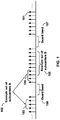
- FIG. 1 is a diagram depicting example sets of OFDM subcarriers as per an aspect of an embodiment of the present invention.
- arrow(s) in the diagram may depict a subcarrier in a multicarrier OFDM system.
- the OFDM system may use technology such as OFDM technology, SC-OFDM technology, or the like.
- arrow 101 shows a subcarrier transmitting information symbols.
- FIG. 1 is for illustration purposes, and a typical multicarrier OFDM system may include more subcarriers in a carrier.
- the number of subcarriers in a carrier may be in the range of 10 to 10,000 subcarriers.
- FIG. 1 shows two guard bands 106 and 107 in a transmission band. As illustrated in FIG.
- guard band 106 is between subcarriers 103 and subcarriers 104.
- the example set of subcarriers A 102 includes subcarriers 103 and subcarriers 104.
- FIG. 1 also illustrates an example set of subcarriers B 105. As illustrated, there is no guard band between any two subcarriers in the example set of subcarriers B 105.
- Carriers in a multicarrier OFDM communication system may be contiguous carriers, non-contiguous carriers, or a combination of both contiguous and non-contiguous carriers.
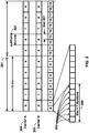
- FIG. 2 is a diagram depicting an example transmission time and reception time for two carriers as per an aspect of an embodiment of the present invention.
- a multicarrier OFDM communication system may include one or more carriers, for example, ranging from 1 to 10 carriers.
- Carrier A 204 and carrier B 205 may have the same or different timing structures. Although FIG. 2 shows two synchronized carriers, carrier A 204 and carrier B 205 may or may not be synchronized with each other.
- Different radio frame structures may be supported for FDD and TDD duplex mechanisms.
- FIG. 2 shows an example FDD frame timing. Downlink and uplink transmissions may be organized into radio frames 201. In this example, radio frame duration is 10 msec. Other frame durations, for example, in the range of 1 to 100 msec may also be supported.
- each 10 ms radio frame 201 may be divided into ten equally sized subframes 202. Other subframe durations such as including 0.5 msec, 1 msec, 2 msec, and 5 msec may also be supported.
- Subframe(s) may consist of two or more slots (e.g. slots 206 and 207). For the example of FDD, 10 subframes may be available for downlink transmission and 10 subframes may be available for uplink transmissions in each 10 ms interval. Uplink and downlink transmissions may be separated in the frequency domain. Slot(s) may include a plurality of OFDM symbols 203. The number of OFDM symbols 203 in a slot 206 may depend on the cyclic prefix length and subcarrier spacing.
- FIG. 3 is a diagram depicting OFDM radio resources as per an aspect of an embodiment of the present invention.
- the resource grid structure in time 304 and frequency 305 is illustrated in FIG. 3 .
- the quantity of downlink subcarriers or RBs may depend, at least in part, on the downlink transmission bandwidth 306 configured in the cell.
- the smallest radio resource unit may be called a resource element (e.g. 301).
- Resource elements may be grouped into resource blocks (e.g. 302).
- Resource blocks may be grouped into larger radio resources called Resource Block Groups (RBG) ( e.g. 303).
- RBG Resource Block Groups
- the transmitted signal in slot 206 may be described by one or several resource grids of a plurality of subcarriers and a plurality of OFDM symbols.
- Resource blocks may be used to describe the mapping of certain physical channels to resource elements.
- Other pre-defined groupings of physical resource elements may be implemented in the system depending on the radio technology. For example, 24 subcarriers may be grouped as a radio block for a duration of 5 msec.
- a resource block may correspond to one slot in the time domain and 180 kHz in the frequency domain (for 15 KHz subcarrier bandwidth and 12 subcarriers).
- FIG. 5A, FIG. 5B, FIG. 5C and FIG. 5D are example diagrams for uplink and downlink signal transmission as per an aspect of an embodiment of the present invention.
- FIG. 5A shows an example uplink physical channel.
- the baseband signal representing the physical uplink shared channel may perform the following processes. These functions are illustrated as examples and it is anticipated that other mechanisms may be implemented in various embodiments.
- the functions may comprise scrambling, modulation of scrambled bits to generate complex-valued symbols, mapping of the complex-valued modulation symbols onto one or several transmission layers, transform precoding to generate complex-valued symbols, precoding of the complex-valued symbols, mapping of precoded complex-valued symbols to resource elements, generation of complex-valued time-domain SC-FDMA signal for each antenna port, and/or the like.
- Example modulation and up-conversion to the carrier frequency of the complex-valued SC-FDMA baseband signal for each antenna port and/or the complex-valued PRACH baseband signal is shown in FIG. 5B . Filtering may be employed prior to transmission.
- the baseband signal representing a downlink physical channel may perform the following processes. These functions are illustrated as examples and it is anticipated that other mechanisms may be implemented in various embodiments.
- the functions include scrambling of coded bits in each of the codewords to be transmitted on a physical channel; modulation of scrambled bits to generate complex-valued modulation symbols; mapping of the complex-valued modulation symbols onto one or several transmission layers; precoding of the complex-valued modulation symbols on each layer for transmission on the antenna ports; mapping of complex-valued modulation symbols for each antenna port to resource elements; generation of complex-valued time-domain OFDM signal for each antenna port, and/or the like.
- Example modulation and up-conversion to the carrier frequency of the complex-valued OFDM baseband signal for each antenna port is shown in FIG. 5D .
- Filtering may be employed prior to transmission.
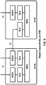
- FIG. 4 is an example block diagram of a base station 401 and a wireless device 406, as per an aspect of an embodiment of the present invention.
- a communication network 400 may include at least one base station 401 and at least one wireless device 406.
- the base station 401 may include at least one communication interface 402, at least one processor 403, and at least one set of program code instructions 405 stored in non-transitory memory 404 and executable by the at least one processor 403.
- the wireless device 406 may include at least one communication interface 407, at least one processor 408, and at least one set of program code instructions 410 stored in non-transitory memory 409 and executable by the at least one processor 408.
- Communication interface 402 in base station 401 may be configured to engage in communication with communication interface 407 in wireless device 406 via a communication path that includes at least one wireless link 411.
- Wireless link 411 may be a bi-directional link.
- Communication interface 407 in wireless device 406 may also be configured to engage in a communication with communication interface 402 in base station 401.
- Base station 401 and wireless device 406 may be configured to send and receive data over wireless link 411 using multiple frequency carriers.
- transceiver(s) may be employed.
- a transceiver is a device that includes both a transmitter and receiver. Transceivers may be employed in devices such as wireless devices, base stations, relay nodes, and/or the like.
- Example embodiments for radio technology implemented in communication interface 402, 407 and wireless link 411 are illustrated are FIG. 1 , FIG. 2 , FIG. 3 , FIG. 5 , and associated text.
- An interface may be a hardware interface, a firmware interface, a software interface, and/or a combination thereof.
- the hardware interface may include connectors, wires, electronic devices such as drivers, amplifiers, and/or the like.
- a software interface may include code stored in a memory device to implement protocol(s), protocol layers, communication drivers, device drivers, combinations thereof, and/or the like.
- a firmware interface may include a combination of embedded hardware and code stored in and/or in communication with a memory device to implement connections, electronic device operations, protocol(s), protocol layers, communication drivers, device drivers, hardware operations, combinations thereof, and/or the like.
- the term configured may relate to the capacity of a device whether the device is in an operational or non-operational state. Configured may also refer to specific settings in a device that effect the operational characteristics of the device whether the device is in an operational or non-operational state. In other words, the hardware, software, firmware, registers, memory values, and/or the like may be "configured" within a device, whether the device is in an operational or nonoperational state, to provide the device with specific characteristics. Terms such as "a control message to cause in a device” may mean that a control message has parameters that may be used to configure specific characteristics in the device, whether the device is in an operational or non-operational state.
- an LTE network may include a multitude of base stations, providing a user plane PDCP/RLC/MAC/PHY and control plane (RRC) protocol terminations towards the wireless device.
- the base station(s) may be interconnected with other base station(s) (e.g. employing an X2 interface).
- the base stations may also be connected employing, for example, an S1 interface to an EPC.
- the base stations may be interconnected to the MME employing the S1-MME interface and to the S-G) employing the S1-U interface.
- the S1 interface may support a many-to-many relation between MMEs / Serving Gateways and base stations.
- a base station may include many sectors for example: 1, 2, 3, 4, or 6 sectors.
- a base station may include many cells, for example, ranging from 1 to 50 cells or more.
- a cell may be categorized, for example, as a primary cell or secondary cell.
- one serving cell may provide the NAS (non-access stratum) mobility information (e.g. TAI), and at RRC connection re-establishment/handover, one serving cell may provide the security input.
- This cell may be referred to as the Primary Cell (PCell).
- the carrier corresponding to the PCell may be the Downlink Primary Component Carrier (DL PCC), while in the uplink, it may be the Uplink Primary Component Carrier (UL PCC).
- DL PCC Downlink Primary Component Carrier
- U PCC Uplink Primary Component Carrier
- SCells may be configured to form together with the PCell a set of serving cells.
- the carrier corresponding to an SCell may be a Downlink Secondary Component Carrier (DL SCC), while in the uplink, it may be an Uplink Secondary Component Carrier (UL SCC).
- DL SCC Downlink Secondary Component Carrier
- UL SCC Uplink Secondary Component Carrier
- An SCell may or may not have an uplink carrier.
- a cell comprising a downlink carrier and optionally an uplink carrier, may be assigned a physical cell ID and a cell index.
- a carrier downlink or uplink
- the cell ID or Cell index may also identify the downlink carrier or uplink carrier of the cell (depending on the context it is used).
- cell ID may be equally referred to a carrier ID, and cell index may be referred to carrier index.
- the physical cell ID or cell index may be assigned to a cell.
- a cell ID may be determined using a synchronization signal transmitted on a downlink carrier.
- a cell index may be determined using RRC messages.
- the specification when the specification refers to a first physical cell ID for a first downlink carrier, the specification may mean the first physical cell ID is for a cell comprising the first downlink carrier.
- the same concept may apply to, for example, carrier activation.
- the specification indicates that a first carrier is activated, the specification may equally mean that the cell comprising the first carrier is activated.
- Embodiments may be configured to operate as needed.
- the disclosed mechanism may be performed when certain criteria are met, for example, in a wireless device, a base station, a radio environment, a network, a combination of the above, and/or the like.
- Example criteria may be based, at least in part, on for example, traffic load, initial system set up, packet sizes, traffic characteristics, a combination of the above, and/or the like.
- traffic load When the one or more criteria are met, various example embodiments may be applied. Therefore, it may be possible to implement example embodiments that selectively implement disclosed protocols.
- a base station may communicate with a mix of wireless devices.
- Wireless devices may support multiple technologies, and/or multiple releases of the same technology. Wireless devices may have some specific capability(ies) depending on its wireless device category and/or capability(ies).
- a base station may comprise multiple sectors.
- this disclosure refers to a base station communicating with a plurality of wireless devices, this disclosure may refer to a subset of the total wireless devices in a coverage area.
- This disclosure may refer to, for example, a plurality of wireless devices of a given LTE release with a given capability and in a given sector of the base station.
- the plurality of wireless devices in this disclosure may refer to a selected plurality of wireless devices, and/or a subset of total wireless devices in a coverage area which perform according to disclosed methods, and/or the like. There may be a plurality of wireless devices in a coverage area that may not comply with the disclosed methods, for example, because those wireless devices perform based on older releases of LTE technology.
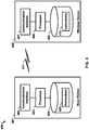
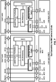
- FIG. 6 and FIG. 7 are example diagrams for protocol structure with CA and DC as per an aspect of an embodiment of the present invention.
- E-UTRAN may support Dual Connectivity (DC) operation whereby a multiple RX/TX UE in RRC_CONNECTED may be configured to utilize radio resources provided by two schedulers located in two eNBs connected via a non-ideal backhaul over the X2 interface.
- eNBs involved in DC for a certain UE may assume two different roles: an eNB may either act as an MeNB or as an SeNB.
- a UE may be connected to one MeNB and one SeNB.
- Mechanisms implemented in DC may be extended to cover more than two eNBs.
- FIG. 1 Dual Connectivity
- FIG. 7 illustrates one example structure for the UE side MAC entities when a Master Cell Group (MCG) and a Secondary Cell Group (SCG) are configured, and it may not restrict implementation.
- MCG Master Cell Group
- SCG Secondary Cell Group
- MBMS Media Broadcast Multicast Service
- the radio protocol architecture that a particular bearer uses may depend on how the bearer is setup. Three alternatives may exist, an MCG bearer, an SCG bearer and a split bearer as shown in FIG. 6 .
- RRC may be located in MeNB and SRBs may be configured as a MCG bearer type and may use the radio resources of the MeNB.
- DC may also be described as having at least one bearer configured to use radio resources provided by the SeNB. DC may or may not be configured/implemented in example embodiments of the invention.
- the UE may be configured with two MAC entities: one MAC entity for MeNB, and one MAC entity for SeNB.
- the configured set of serving cells for a UE may comprise of two subsets: the Master Cell Group (MCG) containing the serving cells of the MeNB, and the Secondary Cell Group (SCG) containing the serving cells of the SeNB.
- MCG Master Cell Group
- SCG Secondary Cell Group
- a SCG For a SCG, one or more of the following may be applied: at least one cell in the SCG has a configured UL CC and one of them, named PSCell (or PCell of SCG, or sometimes called PCell), is configured with PUCCH resources; when the SCG is configured, there may be at least one SCG bearer or one Split bearer; upon detection of a physical layer problem or a random access problem on a PSCell, or the maximum number of RLC retransmissions has been reached associated with the SCG, or upon detection of an access problem on a PSCell during a SCG addition or a SCG change: a RRC connection re-establishment procedure may not be triggered, UL transmissions towards cells of the SCG are stopped, a MeNB may be informed by the UE of a SCG failure type, for split bearer, the DL data transfer over the MeNB is maintained; the RLC AM bearer may be configured for the split bearer; like PCell, PSCell may not be de-activ
- the MeNB may maintain the RRM measurement configuration of the UE and may, (e.g, based on received measurement reports or traffic conditions or bearer types), decide to ask a SeNB to provide additional resources (serving cells) for a UE; upon receiving a request from the MeNB, a SeNB may create a container that may result in the configuration of additional serving cells for the UE (or decide that it has no resource available to do so); for UE capability coordination, the MeNB may provide (part of) the AS configuration and the UE capabilities to the SeNB; the MeNB and the SeNB may exchange information about a UE configuration by employing of RRC containers (inter-node messages) carried in X2 messages; the SeNB may initiate a reconfiguration of its existing serving cells (e.g., PUCCH towards the SeNB); the SeNB may decide which cell is the PSCell within the SCG; the MeNB may not change the content of the RRC
- serving cells having an uplink to which the same time alignment (TA) applies may be grouped in a TA group (TAG).
- Serving cells in one TAG may use the same timing reference.
- user equipment (UE) may use one downlink carrier as a timing reference at a given time.
- the UE may use a downlink carrier in a TAG as a timing reference for that TAG.
- a UE may synchronize uplink subframe and frame transmission timing of uplink carriers belonging to the same TAG.
- serving cells having an uplink to which the same TA applies may correspond to serving cells hosted by the same receiver.
- a TA group may comprise at least one serving cell with a configured uplink.
- a UE supporting multiple TAs may support two or more TA groups.
- One TA group may contain the PCell and may be called a primary TAG (pTAG).
- pTAG primary TAG
- sTAG secondary TAG
- Carriers within the same TA group may use the same TA value and the same timing reference.
- cells belonging to a cell group MCG or SCG
- MCG Mobility Management Entity
- FIG. 8 shows example TAG configurations as per an aspect of an embodiment of the present invention.
- pTAG comprises PCell
- an sTAG comprises SCell1.
- a pTAG comprises a PCell and SCell1
- an sTAG comprises SCell2 and SCell3.
- pTAG comprises PCell and SCell1
- an sTAG1 includes SCell2 and SCell3
- sTAG2 comprises SCell4.
- up to four TAGs may be supported in a cell group (MCG or SCG) and other example TAG configurations may also be provided.
- example mechanisms are described for a pTAG and an sTAG. The operation with one example sTAG is described, and the same operation may be applicable to other sTAGs. The example mechanisms may be applied to configurations with multiple sTAGs.
- TA maintenance, pathloss reference handling and a timing reference for a pTAG may follow LTE release 10 principles in the MCG and/or SCG.
- the UE may need to measure downlink pathloss to calculate uplink transmit power.
- a pathloss reference may be used for uplink power control and/or transmission of random access preamble(s).
- UE may measure downlink pathloss using signals received on a pathloss reference cell.
- a pathloss reference for cells may be selected from and/or be limited to the following two options: a) the downlink SCell linked to an uplink SCell using system information block 2 (SIB2), and b) the downlink pCell.
- SIB2 system information block 2
- the pathloss reference for SCells in a pTAG may be configurable using RRC message(s) as a part of an SCell initial configuration and/or reconfiguration.
- a PhysicalConfigDedicatedSCell information element (IE) of an SCell configuration may include a pathloss reference SCell (downlink carrier) for an SCell in a pTAG.
- the downlink SCell linked to an uplink SCell using system information block 2 (SIB2) may be referred to as the SIB2 linked downlink of the SCell.
- SIB2 system information block 2
- Different TAGs may operate in different bands.
- the pathloss reference may be only configurable to the downlink SCell linked to an uplink SCell using the system information block 2 (SIB2) of the SCell.
- an eNB may initiate an RA procedure.
- a UE may use one of any activated SCells from this sTAG as a timing reference cell.
- the timing reference for SCells in an sTAG may be the SIB2 linked downlink of the SCell on which the preamble for the latest RA procedure was sent.
- TAT time alignment timer
- a TAT associated with a pTAG expires: all TATs may be considered as expired, the UE may flush HARQ buffers of serving cells, the UE may clear any configured downlink assignment/uplink grants, and the RRC in the UE may release PUCCH/SRS for all configured serving cells.
- the pTAG TAT is not running, an sTAG TAT may not be running.
- a) SRS transmissions may be stopped on the corresponding SCells, b) SRS RRC configuration may be released, c) CSI reporting configuration for corresponding SCells may be maintained, and/or d) the MAC in the UE may flush the uplink HARQ buffers of the corresponding SCells.
- An eNB may initiate an RA procedure via a PDCCH order for an activated SCell.
- This PDCCH order may be sent on a scheduling cell of this SCell.
- the scheduling cell may be different than the cell that is employed for preamble transmission, and the PDCCH order may include an SCell index.
- At least a non-contention based RA procedure may be supported for SCell(s) assigned to sTAG(s).
- FIG. 9 is an example message flow in a random access process in a secondary TAG as per an aspect of an embodiment of the present invention.
- An eNB transmits an activation command 600 to activate an SCell.
- a preamble 602 (Msg1) may be sent by a UE in response to a PDCCH order 601 on an SCell belonging to an sTAG.
- preamble transmission for SCells may be controlled by the network using PDCCH format 1A.
- Msg2 message 603 RAR: random access response
- RAR random access response
- Uplink packets 604 may be transmitted on the SCell in which the preamble was transmitted.
- initial timing alignment may be achieved through a random access procedure. This may involve a UE transmitting a random access preamble and an eNB responding with an initial TA command NTA (amount of timing advance) within a random access response window.
- NTA amount of timing advance
- the eNB may estimate the uplink timing from the random access preamble transmitted by the UE.
- the TA command may be derived by the eNB based on the estimation of the difference between the desired UL timing and the actual UL timing.
- the UE may determine the initial uplink transmission timing relative to the corresponding downlink of the sTAG on which the preamble is transmitted.
- the mapping of a serving cell to a TAG may be configured by a serving eNB with RRC signaling.
- the mechanism for TAG configuration and reconfiguration may be based on RRC signaling.
- the related TAG configuration may be configured for the SCell.
- an eNB may modify the TAG configuration of an SCell by removing (releasing) the SCell and adding(configuring) a new SCell (with the same physical cell ID and frequency) with an updated TAG ID.
- the new SCell with the updated TAG ID may initially be inactive subsequent to being assigned the updated TAG ID.
- the eNB may activate the updated new SCell and start scheduling packets on the activated SCell.
- the SCell may need to be removed and a new SCell may need to be added with another TAG.
- at least one RRC message for example, at least one RRC reconfiguration message, may be send to the UE to reconfigure TAG configurations by releasing the SCell and then configuring the SCell as a part of the pTAG (when an SCell is added/configured without a TAG index, the SCell may be explicitly assigned to the pTAG).
- the PCell may not change its TA group and may always be a member of the pTAG.
- the purpose of an RRC connection reconfiguration procedure may be to modify an RRC connection, (e.g. to establish, modify and/or release RBs, to perform handover, to setup, modify, and/or release measurements, to add, modify, and/or release SCells). If the received RRC Connection Reconfiguration message includes the sCellToReleaseList, the UE may perform an SCell release. If the received RRC Connection Reconfiguration message includes the sCellToAddModList, the UE may perform SCell additions or modification.
- a PUCCH is only transmitted on the PCell (PSCell) to an eNB.
- a UE may transmit PUCCH information on one cell (PCell or PSCell) to a given eNB.
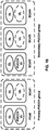
- FIG. 10 is an example grouping of cells into PUCCH groups as per an aspect of an embodiment of the present invention.
- one, two or more cells may be configured with PUCCH resources for transmitting CSI/ACK/NACK to a base station.
- Cells may be grouped into multiple PUCCH groups, and one or more cell within a group may be configured with a PUCCH.
- one SCell may belong to one PUCCH group.
- SCells with a configured PUCCH transmitted to a base station may be called a PUCCH SCell, and a cell group with a common PUCCH resource transmitted to the same base station may be called a PUCCH group.
- a PUCCH can be configured on a PCell and/or a PSCell, but cannot be configured on other SCells.
- a UE may transmit a message indicating that the UE supports PUCCH configuration on a PCell and SCell. Such an indication may be separate from an indication of of dual connectivity support by the UE.
- a UE may support both DC and PUCCH groups. In an example embodiment, either DC or PUCCH groups may be configured, but not both. In another example embodiment, more complicated configurations comprising both DC and PUCCH groups may be supported.
- a UE When a UE is capable of configuring PUCCH groups, and if a UE indicates that it supports simultaneous PUCCH/PUSCH transmission capability, it may imply that the UE supports simultaneous PUCCH/PUSCH transmission on both PCell and SCell. When multiple PUCCH groups are configured, a PUCCH may be configured or not configured with simultaneous PUCCH/PUSCH transmission.
- PUCCH transmission to a base station on two serving cells may be realized as shown in FIG. 10 .
- a first group of cells may employ a PUCCH on the PCell and may be called PUCCH group 1 or a primary PUCCH group.
- a second group of cells may employ a PUCCH on an SCell and may be called PUCCH group 2 or a secondary PUCCH group.
- One, two or more PUCCH groups may be configured.
- cells may be grouped into two PUCCH groups, and each PUCCH group may include a cell with PUCCH resources.
- a PCell may provide PUCCH resources for the primary PUCCH group and an SCell in the secondary PUCCH group may provide PUCCH resources for the cells in the secondary PUCCH group.
- no cross-carrier scheduling between cells in different PUCCH groups may be configured.
- ACK/NACK on PHICH channel may be limited within a PUCCH group. Both downlink and uplink scheduling activity may be separate between cells belonging to different PUCCH groups.
- a PUCCH on an SCell may carry HARQ-ACK and CSI information.
- a PCell may be configured with PUCCH resources.
- RRC parameters for an SCell PUCCH Power Control for a PUCCH on an SCell may be different from those of a PCell PUCCH.
- a Transmit Power Control command for a PUCCH on an SCell may be transmitted in DCI(s) on the SCell carrying the PUCCH.
- UE procedures on a PUCCH transmission may be different and/or independent between PUCCH groups. For example, determination of DL HARQ-ACK timing, PUCCH resource determination for HARQ-ACK and/or CSI, Higher-layer configuration of simultaneous HARQ-ACK + CSI on a PUCCH, Higher-layer configuration of simultaneous HARQ-ACK + SRS in one subframe may be configured differently for a PUCCH PCell and a PUCCH SCell.
- a PUCCH group may be a group of serving cells configured by a RRC and use the same serving cell in the group for transmission of a PUCCH.
- a Primary PUCCH group may be a PUCCH group containing a PCell.
- a secondary PUCCH group may be a PUCCH cell group not containing the PCell.
- an SCell may belong to one PUCCH group. When one SCell belongs to a PUCCH group, ACK/NACK or CSI for that SCell may be transmitted over the PUCCH in that PUCCH group (over PUCCH SCell or PUCCH PCell).
- a PUCCH on an SCell may reduce the PUCCH load on the PCell.
- a PUCCH SCell may be employed for UCI transmission of SCells in the corresponding PUCCH group.
- a flexible PUCCH configuration in which control signalling is sent on one, two or more PUCCHs may be possible. Beside the PCell, it may be possible to configure a selected number of SCells for PUCCH transmission (herein called PUCCH SCells). Control signalling information conveyed in a certain PUCCH SCell may be related to a set of SCells in a corresponding PUCCH group that are configured by the network via RRC signalling.
- PUCCH control signalling carried by a PUCCH channel may be distributed between a PCell and SCells for off-loading or robustness purposes.
- a PUCCH in an SCell it may be possible to distribute the overall CSI reports for a given UE between a PCell and a selected number of SCells (e.g. PUCCH SCells), thereby limiting PUCCH CSI resource consumption by a given UE on a certain cell. It may be possible to map CSI reports for a certain SCell to a selected PUCCH SCell.
- An SCell may be assigned a certain periodicity and time-offset for transmission of control information.
- Periodic CSI for a serving cell may be mapped on a PUCCH (on the PCell or on a PUCCH-SCell) via RRC signalling.
- the possibility of distributing CSI reports, HARQ feedbacks, and /or Scheduling Requests across PUCCH SCells may provide flexibility and capacity improvements.
- HARQ feedback for a serving cell may be mapped on a PUCCH (on the PCell or on a PUCCH SCell) via RRC signalling.
- PUCCH transmission may be configured on a PCell, as well as one SCell in CA.
- An SCell PUCCH may be realized using the concept of PUCCH groups, where aggregated cells are grouped into two or more PUCCH groups.
- One cell from a PUCCH group may be configured to carry a PUCCH. More than 5 carriers may be configured.
- up to n carriers may be aggregated. For example, n may be 16, 32, or 64.
- Some CCs may have non-backward compatible configurations supporting only advanced UEs (e.g. support licensed assisted access SCells).
- one SCell PUCCH (e.g. two PUCCH groups) may be supported.
- a PUCCH group concept with multiple (more than one) SCells carrying PUCCH may be employed (e.g. , there can be more than two PUCCH groups).
- a given PUCCH group may not comprise serving cells of both MCG and SCG.
- One of the PUCCHs may be configured on the PCell.
- PUCCH mapping of serving cells may be configured by RRC messages.
- a maximum value of an SCellIndex and a ServCellIndex may be 31 (ranging from 0 to 31).
- a maximum value of stag-Id may be 3.
- the CIF for a scheduled cell may be configured explicitly.
- a PUCCH SCell may be configured by giving a PUCCH configuration for an SCell.
- a HARQ feedback and CSI report of a PUCCH SCell may be sent on the PUCCH of that PUCCH SCell.
- the HARQ feedback and CSI report of a SCell may sent on a PUCCH of a PCell if no PUCCH SCell is signalled for that SCell.
- the HARQ feedback and CSI report of an SCell may be sent on the PUCCH of one PUCCH SCell; hence they may not be sent on the PUCCH of different PUCCH SCell.
- the UE may report a Type 2 PH for serving cells configured with a PUCCH.
- a MAC activation/deactivation may be supported for a PUCCH SCell.
- An eNB may manage the activation/deactivation status for SCells.
- a newly added PUCCH SCell may be initially deactivated.
- FIG. 11 and FIG. 12 show example configurations of TAGs and PUCCH groups.
- one TAG may contain multiple serving cells with a PUCCH.
- each TAG may only comprise cells of one PUCCH group.
- a TAG may comprise the serving cells (without a PUCCH) which belong to different PUCCH groups.
- a PUCCH SCell may belong to primary TAG.
- the serving cells of one PUCCH group may be in different TAGs and serving cells of one TAG may be in different PUCCH groups.
- Configuration of PUCCH groups and TAGs may be left to eNB implementation.
- restriction(s) on the configuration of a PUCCH cell may be specified.
- cells in a given PUCCH group may belong to the same TAG.
- an sTAG may only comprise cells of one PUCCH group.
- one-to-one mapping between TAGs and PUCCH groups may be implemented.
- cell configurations may be limited to some of the examples. In other implementations, some or all the below configurations may be allowed.
- the timing reference may be a PCell.
- the timing reference may be any activated SCell in the sTAG.
- a pathloss reference may be configured to be a PCell or an SIB-2 linked SCell.
- the pathloss reference may be the SIB-2 linked SCell.
- the MAC may indicate to an RRC to release PUCCH resource for the PUCCH group.
- the uplink transmission (PUSCH) for SCells in the secondary PUCCH group not belonging to the sTAG including the PUCCH SCell may not be impacted.
- the TAT expiry of an sTAG containing a PUCCH SCell may not trigger TAT expiry of other TAGs to which other SCells in the same PUCCH group belong.
- the wireless device may stop the uplink transmission for the SCell in the sTAG and may not impact other TAGs.
- a MAC entity may have a configurable timer timeAlignmentTimer per TAG.
- the timeAlignmentTimer may be used to control how long the MAC entity considers the Serving Cells belonging to the associated TAG to be uplink time aligned.
- the MAC entity may, when a Timing Advance Command MAC control element is received, apply the Timing Advance Command for the indicated TAG; start or restart the timeAlignmentTimer associated with the indicated TAG.
- the MAC entity may, when a Timing Advance Command is received in a Random Access Response message for a serving cell belonging to a TAG and/orif the Random Access Preamble was not selected by the MAC entity, apply the Timing Advance Command for this TAG and start or restart the timeAlignmentTimer associated with this TAG. Otherwise, if the timeAlignmentTimer associated with this TAG is not running, the Timing Advance Command for this TAG may be applied and the timeAlignmentTimer associated with this TAG started. When the contention resolution is considered not successful, a timeAlignmentTimer associated with this TAG may be stopped. Otherwise, the MAC entity may ignore the received Timing Advance Command.
- Example embodiments of the invention may enable operation of multiple PUCCH groups.
- Other example embodiments may comprise a non-transitory tangible computer readable media comprising instructions executable by one or more processors to cause operation of PUCCH groups.
- Yet other example embodiments may comprise an article of manufacture that comprises a non-transitory tangible computer readable machine-accessible medium having instructions encoded thereon for enabling programmable hardware to cause a device (e.g. wireless communicator, UE, base station, etc.) to enable operation of PUCCH groups.
- the device may include processors, memory, interfaces, and/or the like.
- Other example embodiments may comprise communication networks comprising devices such as base stations, wireless devices (or user equipment: UE), servers, switches, antennas, and/or the like.
- one or more TAGs may be configured along with PUCCH group configuration.
- FIG. 13 is an example MAC PDU as per an aspect of an embodiment of the present invention.
- a MAC PDU may comprise of a MAC header, zero or more MAC Service Data Units (MAC SDU), zero or more MAC control elements, and optionally padding.
- the MAC header and the MAC SDUs may be of variable sizes.
- a MAC PDU header may comprise one or more MAC PDU subheaders.
- a subheader may correspond to either a MAC SDU, a MAC control element or padding.
- a MAC PDU subheader may comprise header fields R, F2, E, LCID, F, and/or L.
- the last subheader in the MAC PDU and subheaders for fixed sized MAC control elements may comprise the four header fields R, F2, E, and/or LCID.
- a MAC PDU subheader corresponding to padding may comprise the four header fields R, F2, E, and/or LCID.
- LCID or Logical Channel ID field may identify the logical channel instance of the corresponding MAC SDU or the type of the corresponding MAC control element or padding.
- one or two additional LCID fields may be included in the MAC PDU when single-byte or two-byte padding is required but cannot be achieved by padding at the end of the MAC PDU.
- the LCID field size may be, e.g. 5 bits.
- L or the Length field may indicate the length of the corresponding MAC SDU or variable-sized MAC control element in bytes.
- the size of the L field may be indicated by the F field and F2 field.
- the F or the Format field may indicate the size of the Length field.
- the size of the F field may be 1 bit. In an example, if the F field is included, and/or if the size of the MAC SDU or variable-sized MAC control element is less than 128 bytes, the value of the F field is set to 0, otherwise it is set to 1.
- the F2 or the Format2 field may indicate the size of the Length field. There may be one F2 field per MAC PDU subheader. The size of the F2 field may be 1 bit. In an example, if the size of the MAC SDU or variable-sized MAC control element is larger than 32767 bytes and if the corresponding subheader is not the last subheader, the value of the F2 field may be set to 1, otherwise it is set to 0.
- the E or the Extension field may be a flag indicating if more fields are present in the MAC header or not. The E field may be set to "1" to indicate another set of at least R/F2/E/LCID fields. The E field may be set to "0" to indicate that either a MAC SDU, a MAC control element or padding starts at the next byte. R or reserved bit, set to "0".
- MAC PDU subheaders may have the same order as the corresponding MAC SDUs, MAC control elements and padding.
- MAC control elements may be placed before any MAC SDU.
- Padding may occur at the end of the MAC PDU, except when single-byte or two-byte padding is required. Padding may have any value and the MAC entity may ignore it.
- zero or more padding bytes may be allowed.
- one or two MAC PDU subheaders corresponding to padding may be placed at the beginning of the MAC PDU before any other MAC PDU subheader.
- a maximum of one MAC PDU may be transmitted per TB per MAC entity, a maximum of one MCH MAC PDU can be transmitted per TTI.
- At least one RRC message may provide configuration parameters for at least one cell and configuration parameters for PUCCH groups.
- the information elements in one or more RRC messages may provide mapping between configured cells and PUCCH SCells. Cells may be grouped into a plurality of cell groups and a cell may be assigned to one of the configured PUCCH groups. There may be a one-to-one relationship between PUCCH groups and cells with configured PUCCH resources.
- At least one RRC message may provide mapping between an SCell and a PUCCH group, and PUCCH configuration on PUCCH SCell.
- System information (common parameters) for an SCell may be carried in a RadioResourceConfigCommonSCell in a dedicated RRC message. Some of the PUCCH related information may be included in common information of an SCell ( e.g. in the RadioResourceConfigCommonSCell). Dedicated configuration parameters of SCell and PUCCH resources may be configured by dedicated RRC signaling using, for example, RadioResourceConfigDedicatedSCell.
- the IE PUCCH-ConfigCommon and IE PUCCH-ConfigDedicated may be used to specify the common and the UE specific PUCCH configuration respectively.
- PUCCH-ConfigCommon may include: deltaPUCCH-Shift: ENUMERATED ⁇ ds1, ds2, ds3 ⁇ ; nRB-CQI: INTEGER (0..98); nCS-AN: INTEGER (0..7); and/or n1PUCCH-AN: INTEGER (0..2047).
- the parameter deltaPUCCH-Shift ( ⁇ shift PUCCH ) , nRB ⁇ CQI N RB 2 , nCS ⁇ An N cs 1 , and n 1 PUCCH ⁇ AN N PUCCH 1 may be physical layer parameters of PUCCH.
- PUCCH-ConfigDedicated may be employed.
- PUCCH-ConfigDedicated may include: ackNackRepetition CHOICE ⁇ release: NULL, setup: SEQUENCE ⁇ repetitionFactor: ENUMERATED ⁇ n2, n4, n6, spare1 ⁇ ,n1PUCCH-AN-Rep: INTEGER (0..2047) ⁇ , tdd-AckNackFeedbackMode: ENUMERATED ⁇ bundling, multiplexing ⁇ OPTIONAL ⁇ .
- ackNackRepetitionj parameter indicates whether ACK/NACK repetition is configured.
- n2 corresponds to repetition factor 2, n4 to 4 for repetitionFactor parameter ( N ANRep ).
- n1PUCCH-AN-Rep parameter may be n PUCCH , ANRep 1 p for antenna port P0 and for antenna port P1.
- dd-AckNackFeedbackMode parameter may indicate one of the TDD ACK/NACK feedback modes used.
- the value bundling may correspond to use of ACK/NACK bundling whereas, the value multiplexing may correspond to ACK/NACK multiplexing. The same value may apply to both ACK/NACK feedback modes on PUCCH as well as on PUSCH.
- the parameter PUCCH-ConfigDedicated may include simultaneous PUCCH-PUSCH parameter indicating whether simultaneous PUCCH and PUSCH transmissions is configured.
- An E-UTRAN may configure this field for the PCell when the nonContiguousUL-RA-WithinCC-Info is set to supported in the band on which PCell is configured.
- the E-UTRAN may configure this field for the PSCell when the nonContiguousUL-RA-WithinCC-Info is set to supported in the band on which PSCell is configured.
- the E-UTRAN may configure this field for the PUCCH SCell when the nonContiguousUL-RA-WithinCC-Info is set to supported in the band on which PUCCH SCell is configured.
- a UE may transmit radio capabilities to an eNB to indicate whether UE support the configuration of PUCCH groups.
- the simultaneous PUCCH-PUSCH in the UE capability message may be applied to both a PCell and an SCell.
- Simultaneous PUCCH+PUSCH may be configured separately (using separate IEs) for a PCell and a PUCCH SCell.
- a PCell and a PUCCH SCell may have different or the same configurations related to simultaneous PUCCH+PUSCH.
- the eNB may select the PUCCH SCell among current SCells or candidate SCells considering cell loading, carrier quality (e.g. using measurement reports), carrier configuration, and/or other parameters.
- a PUCCH Cell group management procedure may include a PUCCH Cell group addition, a PUCCH cell group release, a PUCCH cell group change and/or a PUCCH cell group reconfiguration.
- the PUCCH cell group addition procedure may be used to add a secondary PUCCH cell group (e.g., to add PUCCH SCell and one or more SCells in the secondary PUCCH cell group).
- cells may be released and added employing one or more RRC messages.
- cells may be released employing a first RRC message and then added employing a second RRC messages.
- SCells including PUCCH SCell may be in a deactivated state when they are configured.
- a PUCCH SCell may be activated after an RRC configuration procedure by an activation MAC CE.
- An eNB may transmit a MAC CE activation command to a UE.
- the UE may activate an SCell in response to receiving the MAC CE activation command.
- a timer is running once it is started, until it is stopped or until it expires; otherwise it may not be running.
- a timer can be started if it is not running or restarted if it is running.
- a timer may be started or restarted from its initial value.
- Example power headroom trigger condition configuration parameters in an RRC message are shown below. Other examples may be implemented.
- the parameter periodicPHR-Timer may be a timer for PHR reporting. Value in number of sub-frames. Value sf10 corresponds to 10 subframes, sf20 corresponds to 20 subframes and so on.
- the parameter prohibitPHR-Timer may be a timer for PHR reporting. Value in number of sub-frames. Value sf0 corresponds to 0 subframes, sf100 corresponds to 100 subframes and so on.
- the parameter dl-PathlossChange may be DL Pathloss Change and the change of the required power backoff due to power management (as allowed by P-MPRc) for PHR reporting.
- Value dB 1 corresponds to 1 dB
- dB3 corresponds to 3 dB and so on. The same value may apply for each serving cell (although the associated functionality is performed independently for each cell).
- a Power Headroom reporting procedure may be employed to provide a serving eNB with information about the difference between nominal UE maximum transmit power and estimated power for UL-SCH transmission per activated serving cell.
- the Power Headroom reporting procedure may also to provide a serving eNB with information about the difference between the nominal UE maximum power and the estimated power for an UL-SCH and PUCCH transmission on a SpCell and/or a PUCCH SCell.
- the reporting period, delay and mapping of Power Headroom may be defined.
- An RRC may control Power Headroom reporting by configuring at least two timers periodicPHR-Timer and prohibitPHR-Timer, and by signalling dl-PathlossChange which may set the change in measured downlink pathloss and the power backoff due to power management (as allowed by P-MPR c ) to trigger a PHR.
- a Power Headroom Report may be triggered if one or more of the following events occur (not listed in any particuar order).
- a prohibitPHR-Timer expires or has expired and the path loss has changed more than dl-PathlossChange dB for at least one activated serving cell of any MAC entity which is used as a pathloss reference since the last transmission of a PHR in this MAC entity when the MAC entity has UL resources for new transmission.
- a periodicPHR-Timer expires.
- the MAC entity may avoid triggering a PHR when the required power backoff due to power management decreases temporarily (e.g. for up to a few tens of milliseconds) and it may avoid reflecting such temporary decrease in the values of PCMAX,c/PH when a PHR is triggered by other triggering conditions.
- the MAC entity may start a periodicPHR-Timer if it is the first UL resource allocated for a new transmission since the last MAC reset.
- a UE may transmit a corresponding PHR report if a Power Headroom reporting procedure determines that at least one PHR has been triggered and not cancelled, and if the allocated UL resources can accommodate a corresponding PHR MAC control element plus its subheader for a corresponding PHR configuration as a result of logical channel prioritization.
- a UE may transmit a corresponding PHR report for one or more activated serving cells with a configured uplink if: the allocated UL resources can accommodate a PHR MAC control element plus its subheader if neither extendedPHR nor dualConnectivityPHR is configured, and/or an Extended PHR MAC control element plus its subheader if an extendedPHR is configured, and/or a Dual Connectivity PHR MAC control element plus its subheader if dualConnectivityPHR is configured as a result of logical channel prioritization.
- an Extended Power Headroom Report (PHR) MAC Control Element was introduced to accomodate type 2 power headroom (PH) of PCell and type 1 PHs of SCells.
- Type 2 PH may be employed when simultaneousPUCCH-PUSCH configuration is supported.
- the PHR MAC CE may contain 2 type 2 PHs and several type 1 PHs.
- DC PHR MAC CE was introduced to include an extra type 2 PH of a PSCell. For DC, PH may be reported to both eNBs separately, but the PHR may include PH for active serving cells.
- a MAC CE may be identified by a logical channel ID (LCID) field in a MAC subheader.
- the LCID field may identify the logical channel instance of the corresponding MAC SDU and/or the type of the corresponding MAC control element and/or padding.
- LCID for UL-SCH MAC CE in Release-12 are defined in 3GPP TS 36.321 V12.4.0 as: Index 11000: Dual Connectivity Power Headroom Report; Index 11001: Extended Power Headroom Report; and Index 11010: Power Headroom Report
- a UE may generate and transmit a Power Headroom Report with, for example, an LCID of 11010.
- LTE Release-12 does not appear to address configuration, message format, trigger conditions, and message processing for power headroom when a PUCCH SCell with simultaneous PUCCH+PUSCH transmissions is configured in a UE (without configuring DC in the UE).
- a Release-12 Dual Connectivity Power Headroom Report may not be applicable in such a scenario, since dual connectivity may not be configured in the UE.
- a Release-12 Extended Power Headroom Report may not be applicable since it does not appear to support transmission of two Type 2 power headrooms when PUCCH groups are configured.
- a Release-12 Power Headroom Report report may not be applicable since it appears to support only one serving cell. There may be a need for enhancing the power headroom implementation to efficiently support PUCCH group configuration. There may also be a need for enhancing the power headroom implementation to enhanced cell configurations not supported by existing PHR formats.
- a new PHR may be called an extendedPHR2 MAC CE and/or an extended cell configuration PHR MAC CE and/or a new extended PHR MAC CE.
- the new PHR may also be called by other names (e.g. PUCCH group PHR MAC CE, enhanced configuration MAC CE, 32 cell PHR MAC CE, etc., and/or the like).
- the number of used MAC LCIDs may increase if a new PHR MAC CE command format with a new MAC LCID is implemented for an extendedPHR2.
- a MAC LCID may be included in a MAC subheader.
- an existing MAC LCID may be employed for an extendedPHR2 (e.g. LCID of Dual connectivity or LCID of Extended PHR).
- a UE may transmit PHR MAC CEs to an eNB in unicast messages. Both the UE and the eNB may have information about the current RRC configurations of the UE. The UE may use the same LCID for or one or more PHR transmissions and the UE may identify the format of the PHR based on RRC configuration parameters.
- This enhancement may not require introducing a new LCID for an extendedPHR2.
- Two different power headroom MAC CEs may use the same LCID.
- This mechanism may reduce the number of LCIDs used in the MAC layer (compared with the scenario wherein a new LCID is introduced) and may further simplify a UE implementation.
- RRC configuration parameters in addition to an LCID may be employed to determine the format of the PHR MAC CE.
- a UE may consider UE RRC cell configurations to decide the format of a PHR MAC CE. For example, if a UE is configured with a first RRC configuration for a plualrity of cells (e.g. 5 cells) of an eNB with no configured PUCCH SCell, then the fields in the MAC CE may be updated using processes related to an extendedPHR power headroom. If a UE is configured with PUCCH groups, then the fields in the MAC CE may be updated using processes related to an extendedPHR2 PHR. On the other hand, an eNB receiving the PHR MAC CE may have information about the RRC configuration of the UE transmitting the PHR MAC CE, and may interpret the PHR MAC CE fields based on the corresponding RRC configuration.
- a Type 2 power headroom may be reported when simultaneous PUCCH-PUSCH is configured for a given cell, for example, a PCell and/or a PSCell.
- a PCell and/or a PSCell may be active after being configured.
- Type 1 and Type 2 PH fields for the PCell and the PSCell may be included in a PHR report.
- a PUCCH SCell may be deactivated in some scenarios. If and when a PUCCH SCell is deactivated, there may not be a need to include Type 1 and Type 2 PH reports for the PUCCH SCell in the extendedPHR2 report. This may require implementation of new processes and format for a PHR, in which a Type 2 and/or Type 1 PHR may or may not be reported for the PUCCH SCell.
- the octet containing the Type 2 PH field may be included first after the octet indicating the presence of a PH per cell (PSCell and SCells of MAC entities) and followed by an octet containing an associated PCMAX,c field (if reported).
- the octet containing the Type 2 PH field may be included followed by an octet containing the associated PCMAX,c field (if reported).
- a Type 2 PH field for PUCCH SCell may not be reported when a PUCCH SCell is deactivated (even if a simultaneousPUCCH-PUSCH is configured for the PUCCH SCell).
- the UE may indicate the presence of the Type 2 PH field of the PUCCH SCell using ServCellIndex bits present in a Ci bitmap of the PHR MAC CE. This mechanism may allow selectively transmitting a Type 2 PH for a PUCCH SCell when needed.
- a Type 1 PH and octet with an associated PCMAX,c field may be included ( e.g. in ascending order based on the ServCellIndex).
- a Type 1 may be reported for the PCell and for other serving cells of MAC entities as indicated in the bitmap.
- the UE and eNB may not employ a ServCellIndex bit Ci (or another indicator) to determine the presence of a second type 2 PH after a Type 2 PH for a PCell.
- the UE and eNB may employ a ServCellIndex bit Ci (or another indicator) to determine the presence of a Type 2 PH.
- the example embodiment may enhance the existing implementation process for Type 2 PH field(s) in a PHR MAC CE.
- a second Type 2 PH may or may not be present depending on the value of the ServCellIndex bit Ci (or another indicator) in a PHR.
- a value 0 for a PUCCH SCell index ServCellIndex may indicate a second Type 2 PHR and a PCMAX,c are not reported.
- a value 1 for the PUCCH SCell index ServCellIndex may indicate a second Type 2 PHR is reported.
- the corresponding PCMAX,c may also be reported after the second Type 2 PH (if needed according to PH procedure).
- a UE may receive at least one RRC message comprising configuration parameters for a plurality of cells comprising a primary cell and one or more secondary cells.
- the plurality of cells may be grouped into a plurality of physical uplink control channel (PUCCH) groups comprising: a primary PUCCH group comprising the primary cell; and a secondary PUCCH group comprising a PUCCH secondary cell in the one or more secondary cells.
- the RRC message may comprise one or more parameters indicating whether simultaneous PUCCH and physical uplink shared channel transmission is configured in the primary cell and the PUCCH secondary cell.
- the UE may transmit a power headroom report (PHR) media-access-control control element (MAC CE).
- PHR power headroom report
- MAC CE media-access-control control element
- a PHR MAC CE may comprise: a first parameter indicating a Type 2 power headroom of the primary cell; a second parameter (e.g., ServCellIndex bit Ci corresponding to the PUCCH SCell) indicating whether a Type 2 power headroom of the PUCCH secondary cell is present in the PHR MAC CE; and a third parameter indicating the Type 2 power headroom of the PUCCH secondary cell only if the second parameter indicates the presence of the Type 2 power headroom of the PUCCH secondary cell.
- the Type 2 power headroom of the PUCCH secondary cell is not present then the corresponding PCMAX,c may not be present.
- the second paramter indicates the presence of a Type 2 PHR field for the primary cell and Type 2 PHR field for the PUCCH SCell.
- a Type 2 PHR field for the primary cell and Type 2 PHR field for the PUCCH SCell are included and reported in the PHR report.
- the following process may be implemented in the UE. If an extendedPHR2 is configured, then for each activated serving cell with configured uplink: a) obtain the value of a Type 1 power headroom; and b) if the MAC entity has UL resources allocated for transmission on the serving cell for the TTI, then obtain the value for the corresponding PCMAX,c field from the physical layer.
- an extendedPHR2 is configured and if a PUCCH SCell is configured and activated: a) obtain the value of the Type 2 power headroom for the PCell and PUCCH SCell; and b) obtain the values for the corresponding PCMAX,c fields from the physical layer. Otherwise, If an extendedPHR2 is configured and if a PUCCH SCell is not configured or PUCCH SCell is deactivated: if simultaneous PUCCH-PUSCH is configured for the PCell: a) obtain the value of the Type 2 power headroom for the PCell; and b) obtain the value for the corresponding PCMAX,c field from the physical layer.
- the UE may instruct the multiplexing and assembly procedure to generate and transmit an Extended PHR MAC control element for an extendedPHR2 according to a configured ServCellIndex and the PUCCH(s) for the MAC entity based on the values reported by the physical layer.
- an extendedPHR2 when an extendedPHR2 is configured the following process may be implemented for transmission of Type 2 and PCMAX,c fields in the PHR.
- the wireless device may obtain the value of the Type 2 power headroom for the PCell and the PUCCH SCell for transmission; and the wireless device may obtain the values for the corresponding PCMAX,c fields from the physical layer for transmission.
- a Type 2 PH of a PUCCH SCell and a PCell may be transmitted regardless of whether a simultaneous PUCCH-PUSCH is configured for the PCell and/or the PUCCH SCell. Parallel transmission of a PUCCH and a PUSCH may be possible in different PUCCH groups.
- a PUCCH SCell When a PUCCH SCell is not configured or a PUCCH SCell is de-activated: if simultaneousPUCCH-PUSCH is configured for the PCell, the wireless device may obtain the value of the Type 2 power headroom for the PCell for transmission; and the wireless device may obtain the value for the corresponding PCMAX,c field from the physical layer for transmission. In this case, when a simultaneous PUCCH-PUSCH is not configured for the PCell, a Type 2 PH may not be transmitted for the PCell. When a PUCCH SCell is not configured or a PUCCH SCell is de-activated no Type1 PHR and Type 2 PHR is reported for the PUCCH SCell.
- a new information element may be introduced in a MAC-MainConfig to indicate an extendedPHR2 PHR (or called extended cell configuration PHR, new extended PHR) MAC CE format is employed by the UE to report power headroom.
- the new IE may be called an extendedPHR2 and/or other name.
- the extendedPHR2 IE may indicate if a power headroom is reported using the extendedPHR2 PHR MAC CE (e.g. using value release/setup).
- An E-UTRAN may configure the value setup if a PUCCH SCell is configured (PUCCH groups are configured).
- An E-UTRAN may configure an extendedPHR2 if a phr-Config is configured. The UE may release the extendedPHR2 if the phr-Config is released.
- the extendedPHR2 IE may indicate if power headroom is reported using the extendedPHR2 PHR MAC CE (e.g. using value release/setup).
- An E-UTRAN may configure the value setup if a PUCCH SCell is configured (PUCCH groups are configured).
- An E-UTRAN may configure an extendedPHR2 if a phr-Config is configured.
- the UE may release an extendedPHR2 if pa hr-Config is released.
- An extendedPHR2 IE may indicate if power headroom is reported using an extendedPHR2 PHR MAC CE (e.g. using value release/setup).
- An E-UTRAN may configure an extendedPHR2 if a phr-Config is configured. The UE may release an extendedPHR2 if a phr-Config is released.
- a new RRC configuration parameter (extendedPHR2) may be employed to configure and enable an extendedPHR2 PHR in a UE.
- extendedPHR2 when an extendedPHR2 is set up in the UE, the UE may be set up with multiple cells and PUCCH groups.
- the UE may consider the cell RRC configuration and the extendedPHR2 to determine the format of the extendedPHR2 MAC CE to be transmitted. If the extendedPHR2 is set up, the UE may transmit a PHR using the extendedPHR2 PHR MAC CE format and an LCID when required.
- an extendedPHR2 PHR report format may be used, and a Ci value for the PUCCH SCell may be set to a value ( e.g. 0) indicating that the PUCCH SCell is deactivated.
- a predefined format and/or values in a MACE CE may be employed to indicate that a PUCCH SCell is deactivated.
- a UE may not transmit Type 1 and Type 2 PH reports for a deactivated PUCCH SCell.
- Using a new IE in MAC-MainConfig in an RRC message may provide flexibility in the implementation of extendedPHR2 and provide capability to configure additional parameters for extendedPHR2 PHR and provide additional PHR reporting capabilities in the UE.
- Extended Power Headroom Report MAC Control Elements may comprise one or more fields.
- the Extended Power Headroom Report (PHR) MAC control element may be identified by a MAC PDU subheader with an LCID and/or RRC configuration.
- the Extended PHR MAC CE may have a variable size.
- the octet containing the Type 2 PH field may be included first after the octet indicating the presence of a PH per SCell and followed by an octet containing an associated PCMAX,c field (if reported).
- the Extended Power Headroom Report (PHR) MAC control elements may be identified by a MAC PDU subheader with an LCID and/or an RRC configuration. They may have variable sizes.
- One or more octets with C fields may be used for indicating the presence of PH per SCell.
- the octet containing the Type 2 PH field may be included first after the octet(s) indicating the presence of a PH per SCell and followed by an octet containing an associated PCMAX,c field (if reported).
- the it may follow the Type 2 PH field for the PUCCH SCell (if the PUCCH on the SCell is configured and Type 2 PH may be reported for the PUCCH SCell), followed by an octet containing an associated PCMAX,c field (if reported). It may follow in ascending order based on the ServCellIndex an octet with the Type 1 PH field and an octet with the associated PCMAX,c field (if reported), for the PCell and for each SCell indicated in the bitmap.
- Extended PHR MAC Control Elements may be defined as follows.
- a Ci field may indicate the presence of a PH field for an SCell with a SCellIndex i.
- the Ci field set to "1" may indicate that a PH field for the SCell with an SCellIndex i is reported.
- the Ci field set to "0" may indicate that a PH field for the SCell with an SCellIndex i is not reported.
- An “R” field may be a reserved bit set to "0".
- a Power Headroom (PH) field may indicate the power headroom level. The length of the field may be, for example, 6 bits.
- a "P" field may indicate whether the MAC entity applies a power backoff due to power management (as allowed by P-MPRc).
- a "PCMAX,c" field if present, may indicate the PCMAX,c or P ⁇ CMAX,c used for calculation of the preceding PH field.
- a UE power headroom PH may be valid for subframe i for serving cell c.
- the UE may compute PH assuming that it does not transmit a PUSCH/PUCCH on any serving cell of the other CG.
- the term 'serving cell' may refer to a serving cell belonging to the MCG.
- the term 'serving cell' may refer to a serving cell belonging to the SCG.
- the term 'primary cell' may refer to the PSCell of the SCG.
- the term 'serving cell' may refer to a serving cell belonging to the primary PUCCH group.
- the term 'serving cell' may refer to serving cell belonging to the secondary PUCCH group.
- the term 'primary cell' may refer to the PUCCH-SCell of the secondary PUCCH group.
- Example parameters and example calculation method is presented in standard document 3GPP TS 36.213 standard documents of the corresponding LTE release.
- P CMAX , c ( i ), M PUSCH,c ( i ), P O_PUSCH,c ( j ), ⁇ c ( j ) , PL c , ⁇ TF,c ( i ) and f c ( i ) may be defined as follows.
- P CMAX,c ( i ) may be the configured UE transmit power in subframe i for serving cell and P ⁇ CMAX,c ( i ) may be the linear value of P CMAX,c ( i ) .
- M PUSCH,c ( i ) may be the bandwidth of the PUSCH resource assignment expressed in number of resource blocks valid for subframe i and serving cell c .
- Po_PUSCH, c(j) may be configured employing RRC configuration parameters. If the UE is configured with higher layer parameter UplinkPowerControlDedicated-v12x0 for serving cell c and if subframe i belongs to uplink power control subframe set 2 as indicated by the higher layer parameter tpc-SubframeSet-r12.
- ⁇ c ( j ) ⁇ c,2 ⁇ ⁇ 0, 0.4, 0.5, 0.6, 0.7, 0.8, 0.9, 1 ⁇ .
- ⁇ c ,2 is the parameter alpha-SubframeSet2-r12 provided by higher layers for each serving cell c .
- ⁇ c ( j ) 1 .
- ⁇ c ⁇ ⁇ 0, 0.4, 0.5, 0.6, 0.7, 0.8, 0,9, 1 ⁇ may be a 3-bit parameter provided by higher layers for serving cell c .
- BPRE and ⁇ offset PUSCH for each serving cell c , are computed as below.
- K S 0 for transmission mode 2.
- f(i) may be a function of power control commands.
- the UE may measure on or more pathloss values employing signals received on one or more pathloss reference cells.
- a pathloss reference cell may be configured for a serving cell.
- the UE may calculate PL c and may employ one or more pathloss values ( PL c ) for calculation of Type 1 and Type 2 power headroom fields.
- serving cell c belongs to a TAG containing the primary cell then, for the uplink of the primary cell, the primary cell may be used as the reference serving cell for determining referenceSignalPower and higher layer filtered RSRP.
- the serving cell configured by the higher layer parameter pathlossReferenceLinking may be used as the reference serving cell for determining referenceSignalPower and higher layer filtered RSRP.
- the PSCell may be used as the reference serving cell for determining referenceSignalPower and higher layer filtered RSRP.
- the serving cell configured by the higher layer parameter pathlossReferenceLinking may be used as the reference serving cell for determining referenceSignalPower and higher layer filtered RSRP.
- the physical layer may deliver P ⁇ CMAX,c ( i ) instead of P CMAX, c ( i ) to higher layers.
- PH type 2 i P CMAX , c i ⁇ 10 log 10 10 10 log 10 M PUSCH , c i + P O_PUSCH , c j + ⁇ c j ⁇ PL c + ⁇ TF , c i + f c i / 10 + 10 P 0 _PUCCH + PL c + h n CQI n HARQ n SR + ⁇ F_PUCCH F + ⁇ TxD F ′ + g i / 10 dB
- PH type 2 i P CMAX , c i ⁇ 10 log 10 10 P O_PUSCH , c 1 + ⁇ c 1 ⁇ PL c + f c i / 10 + 10 P 0 _PUCCH + PL c + h n CQI n HARQ n SR + ⁇ F_PUCCH F + ⁇ TxD F ′ + g i / 10 dB
- P O_PUSCH,c (1), ⁇ c (1) and f c ( i ) are the primary cell parameters.
- PH type 2 i P ⁇ CMAX , c i ⁇ 10 log 10 10 P O_PUSCH , c 1 + ⁇ c 1 ⁇ PL c + f c i / 10 + 10 P 0 _PUCCH + PL c + g i / 10 dB
- P O_PUSCH,c (1), ⁇ c (1) and f c ( i ) are the primary cell parameters.
- the power headroom may be rounded to the closest value in the range [40; -23] dB with steps of 1 dB and is delivered by the physical layer to higher layers.
- the UE may use f c, 2 ( i ) instead of f c ( i ) to compute PH type1,c ( i ) and PH type2 , c ( i ) for subframe i and serving cell c .
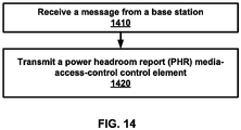
- FIG. 14 is an example flow diagram as per an aspect of an embodiment of the present invention.
- a wireless device receives at least one message from a base station at 1410.
- the message may comprise configuration parameters of a plurality of cells.
- the plurality of cells may comprise a primary cell and a PUCCH secondary cell.
- the primary cell may comprise a primary physical uplink control channel (PUCCH) transmitted to the base station.
- the PUCCH secondary cell may comprise a secondary PUCCH transmitted to the base station.
- PUCCH physical uplink control channel
- a power headroom report (PHR) media-access-control control element (MAC CE) may be transmitted by the UE (wireless device) at 1420.
- the PHR MAC CE may comprise a first field and a second field.
- the first field may indicate whether a Type 2 power headroom field for the PUCCH secondary cell is present in the PHR MAC CE.
- the second field may indicate a Type 2 power headroom level for the PUCCH secondary cell only if the first field indicates the presence of the Type 2 power headroom field for the PUCCH secondary cell.
- the at least one message may further comprise a first information element indicating whether simultaneous PUCCH transmission and a physical uplink shared channel transmission may be configured for the primary cell.
- the at least one message may further comprise a second information element indicating whether simultaneous PUCCH transmission and physical uplink shared channel transmission is configured for the PUCCH secondary cell.
- the PHR MAC CE may further comprise a third field indicating a Type 2 power headroom level for the primary cell.
- the PHR MAC CE may comprise a Type 1 power headroom field for the PUCCH secondary cell different from the Type 2 power headroom field for the PUCCH secondary cell.
- the PHR MAC CE may be employed by the base station for at least one of uplink packet scheduling or uplink power control.
- a calculation of the Type 2 power headroom level may employ a calculated power of a physical uplink control channel and a calculated power of a physical uplink shared channel.
- a calculation of a Type 1 power headroom level may employ the calculated power of a physical uplink shared channel.
- a measurement value may be obtained by measuring a signal of a pathloss reference.
- the calculation of the Type 2 power headroom level may employ the measurement value.
- the wireless device may report the Type 2 power headroom level for the PUCCH secondary cell and a Type 2 power headroom for the primary cell when the PUCCH secondary cell is activated.
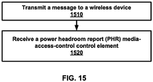
- FIG. 15 is an example flow diagram as per an aspect of an embodiment of the present invention.
- a base station transmits at least one message to a wireless device at 1510.
- the message may comprise configuration parameters of a plurality of cells.
- the plurality of cells may comprise a primary cell and a PUCCH secondary cell.
- the primary cell may comprise a primary physical uplink control channel (PUCCH) transmitted to the base station.
- the PUCCH secondary cell may comprise a secondary PUCCH transmitted to the base station.
- a power headroom report (PHR) media-access-control control element (MAC CE) may be received at 1520.
- the PHR MAC CE may comprise a first field, a second field, and a third field.
- the first field may indicate that a Type 2 power headroom field for the PUCCH secondary cell is present in the PHR MAC CE.
- the second field may indicate a Type 2 power headroom level for the PUCCH secondary cell.
- the third field may indicate a Type 2 power headroom level for the primary cell.
- the at least one message may comprise a first information element indicating whether simultaneous PUCCH transmission and physical uplink shared channel transmission is configured for the primary cell.
- the message(s) may also comprise a second information element indicating whether simultaneous PUCCH transmission and physical uplink shared channel transmission is configured for the PUCCH secondary cell.
- the PHR MAC CE may comprise a fourth field indicating a Type 1 power headroom level for the primary cell.
- the PHR MAC CE may comprise a Type 1 power headroom field for the PUCCH secondary cell that is different from the Type 2 power headroom field for the PUCCH secondary cell.
- the PHR MAC CE may be employed by the base station for uplink packet scheduling and/or uplink power control.
- the base station may receive a Type 2 power headroom level for the PUCCH secondary cell and a Type 2 power headroom level for the primary cell when the PUCCH secondary cell is activated in the wireless device.
- a primary PUCCH group may comprise a group of serving cells including a PCell whose PUCCH signaling is associated with the PUCCH on PCell.
- a PUCCH group may comprise either a primary PUCCH group or a secondary PUCCH group.
- a Secondary PUCCH group may comprise a group of SCells whose PUCCH signalling is associated with the PUCCH on the PUCCH SCell.
- a PUCCH may be transmitted on a PCell, a PUCCH SCell (if such is configured in CA) and on a PSCell (in DC).
- the configured set of serving cells for a UE may comprise of one PCell and one or more SCells. If DC is not configured one additional PUCCH may be configured on an SCell and /or the PUCCH SCell.
- an RRC may configure the mapping of each serving cell to a Primary PUCCH group and/or a Secondary PUCCH group, ( e.g., for each SCell, whether the PCell and/or the PUCCH SCell is used for the transmission of ACK/NAKs and CSI reports).
- an extendedPHR2 for each activated Serving Cell with configured uplink: a) the value of the Type 1 power headroom may be obtained. b) If the MAC entity has UL resources allocated for transmission on the Serving Cell for this TTI: the value for the corresponding PCMAX,c field may be obtained from the physical layer. If a PUCCH SCell is configured and activated: a) the value of the Type 2 power headroom for the PCell and PUCCH SCell may be obtained, and/or b) the values for the corresponding PCMAX,c fields from the physical layer may be obtained.
- Extended Power Headroom Report MAC Control Elements the following may be considered.
- the Extended Power Headroom Report (PHR) MAC control elements may be identified by a MAC PDU subheader with an LCID.
- C fields may be employed for indicating the presence of PH per SCell.
- the octet containing the Type 2 PH field may be included first after the octet(s) indicating the presence of PH per SCell and followed by an octet containing the associated PCMAX,c field (if reported).
- the Type 2 PH field for the PUCCH SCell may follow (if a PUCCH on an SCell is configured and a Type 2 PH is reported for the PUCCH SCell), followed by an octet containing the associated PCMAX,c field (if reported). Then an octet with the Type 1 PH field and an octet with the associated PCMAX,c field (if reported) for the PCell and for each SCell indicated in the bitmap may follow in ascending order based on the ServCellIndex.
- the Extended PHR MAC Control Elements may comprise a multitude of fields, at least some of which are discussed here.
- a Ci may indicate the presence of a PH field for the SCell with SCellIndex i.
- the Ci field may be set to "1" to indicate that a PH field for the SCell with SCellIndex i is reported.
- the Ci field may be set to "0" to indicate that a PH field for the SCell with SCellIndex i is not reported.
- An R field may be a reserved bit, set to, for example, "0".
- a V field may indicate if the PH value is based on a real transmission or a reference format.
- a Power Headroom (PH) field may indicate the power headroom level.
- the length of the field may be, for example, 6 bits.
- a PCMAX,c field if present may indicate the PCMAX,c or P ⁇ CMAX, c used for calculation of a preceding PH field.
- FIG. 14 is an example flow diagram as per an aspect of an embodiment of the present invention.
- a wireless device receives at least one message from a base station at 1410.
- the message may comprise configuration parameters of a plurality of cells and a first information element (IE) and a second IE.
- the plurality of cells may be employed to communicate with a base station.
- the IE may indicate that a new extended power headroom report is configured.
- the first IE is configured as setup when a secondary cell in the plurality of cells is configured with a PUCCH and the second IE indicates that a power headroom report is configured as setup.
- an IE When the value of an IE is setup, it implies that the feature represented by the IE is configured in the wireless device (UE).
- the second IE When the second IE is configured as set up, it indicates that power headroom reporting is configured in the UE.
- the first IE When the first IE is configured as setup, it indicates that Extended PHR2 reporting is configured in the UE.
- a media-access-control (MAC) packet comprising a first Type 2 power headroom field of a primary cell and a second Type 2 power headroom field of the secondary cell may be transmitted at 1420 when the secondary cell is activated.
- the MAC packet may comprise a subheader comprising a logical channel identifier (LCID).
- LCID logical channel identifier
- the message(s) may comprise a prohibit power headroom report timer IE, and/or a periodic power headroom report timer IE.
- a cell index of a cell in the plurality of cells may be higher than a predefined value (e.g. 5 or 7).
- a cell index of a cell with a configured uplink may be higher than a predefined value (e.g. 5 or 7).
- a calculation of the second Type 2 power headroom level may employ a calculated power of the PUCCH and a calculated power of a physical uplink shared channel.
- a calculation of a Type 1 power headroom level of the secondary cell may employ a calculated power of the physical uplink shared channel.
- the power headroom report may be configurable as at least one of the following: the power headroom report, a dual connectivity power headroom report, an extended power headroom report, the new extended power headroom report, a combination thereof, and/or the like.
- a wireless device may receive at least one message from a base station at 1410.
- the message may comprise configuration parameters of a plurality of cells and a first information element (IE) and a second IE.
- Each cell in the plurality of cells may have a configured uplink for communication with a base station.
- the first IE may indicate that a new extended power headroom report is configured.
- the first IE may be configured as setup when: a cell index of a first cell in the plurality of cells is higher than a predefined value; and a second IE indicates that a power headroom report is configured as setup.
- MAC media-access-control
- a wireless device may receive at least one message comprising configuration parameters of a plurality of cells. Each cell in the plurality of cells may have a configured uplink for communication with a base station.
- the at least one message may comprise a first IE and a second IE.
- the first IE may indicate a new extended power headroom report (power headroom report) is configured.
- the first IE is configured as setup when: a cell index of a first cell in the plurality of cells is higher than a predefined value (e.g. 5 or 7); and a second IE indicates that a power headroom report is configured as setup.
- the wireless device may transmit a media-access-control (MAC) packet comprising a power headroom value of the first cell.
- MAC media-access-control
- a wireless device may receive at least one message comprising configuration parameters of a plurality of cells. Each cell in the plurality of cells may have a configured uplink for communication with a base station.
- the at least one message may comprise a first IE and a second IE.
- the first IE may indicate a new extended power headroom report (power headroom report) is configured.
- the first IE is configured as setup when: a number of the plurality of cells is higher than a predefined value (e.g. 5, 7 or 8); and a second IE indicates that a power headroom report is configured as setup.
- the wireless device may transmit a media-access-control (MAC) packet comprising a power headroom value of the first cell.
- MAC media-access-control
- parameters may comprise one or more objects, and each of those objects may comprise one or more other objects.
- parameter (IE) N comprises parameter (IE) M
- parameter (IE) M comprises parameter (IE) K
- parameter (IE) K comprises parameter (information element) J
- N comprises K
- N comprises J
- one or more messages comprise a plurality of parameters
- modules may be implemented as modules.
- a module is defined here as an isolatable element that performs a defined function and has a defined interface to other elements.
- the modules described in this disclosure may be implemented in hardware, software in combination with hardware, firmware, wetware (i.e hardware with a biological element) or a combination thereof, all of which are behaviorally equivalent.
- modules may be implemented as a software routine written in a computer language configured to be executed by a hardware machine (such as C, C++, Fortran, Java, Basic, Matlab or the like) or a modeling/simulation program such as Simulink, Stateflow, GNU Script, or LabVIEWMathScript.
- modules using physical hardware that incorporates discrete or programmable analog, digital and/or quantum hardware.
- programmable hardware comprise: computers, microcontrollers, microprocessors, application-specific integrated circuits (ASICs); field programmable gate arrays (FPGAs); and complex programmable logic devices (CPLDs).
- Computers, microcontrollers and microprocessors are programmed using languages such as assembly, C, C++ or the like.
- FPGAs, ASICs and CPLDs are often programmed using hardware description languages (HDL) such as VHSIC hardware description language (VHDL) or Verilog that configure connections between internal hardware modules with lesser functionality on a programmable device.
- HDL hardware description languages
- VHDL VHSIC hardware description language
- Verilog Verilog
- the disclosed methods and systems may be implemented in wireless or wireline systems.
- the features of various embodiments presented in this invention may be combined.
- One or many features (method or system) of one embodiment may be implemented in other embodiments. Only a limited number of example combinations are shown to indicate to one skilled in the art the possibility of features that may be combined in various embodiments to create enhanced transmission and reception systems and methods.
Landscapes
- Engineering & Computer Science (AREA)
- Signal Processing (AREA)
- Computer Networks & Wireless Communication (AREA)
- Mobile Radio Communication Systems (AREA)
Applications Claiming Priority (2)
| Application Number | Priority Date | Filing Date | Title |
|---|---|---|---|
| US201562130554P | 2015-03-09 | 2015-03-09 | |
| PCT/US2016/021201 WO2016144879A1 (en) | 2015-03-09 | 2016-03-07 | Power headroom mechanisms for carrier aggregation |
Publications (2)
| Publication Number | Publication Date |
|---|---|
| EP3130181A1 EP3130181A1 (en) | 2017-02-15 |
| EP3130181B1 true EP3130181B1 (en) | 2017-09-13 |
Family
ID=55699790
Family Applications (1)
| Application Number | Title | Priority Date | Filing Date |
|---|---|---|---|
| EP16715377.4A Active EP3130181B1 (en) | 2015-03-09 | 2016-03-07 | Power headroom mechanisms for carrier aggregation |
Country Status (6)
| Country | Link |
|---|---|
| US (4) | US10182406B2 (enExample) |
| EP (1) | EP3130181B1 (enExample) |
| JP (1) | JP6469248B2 (enExample) |
| KR (1) | KR101833189B1 (enExample) |
| CN (1) | CN107534942B (enExample) |
| WO (1) | WO2016144879A1 (enExample) |
Families Citing this family (45)
| Publication number | Priority date | Publication date | Assignee | Title |
|---|---|---|---|---|
| CN109041246B (zh) * | 2015-02-10 | 2020-01-17 | 华为技术有限公司 | 一种基站、用户终端及载波调度指示方法 |
| US9860029B2 (en) | 2015-03-09 | 2018-01-02 | Ofinno Technologies, Llc | Modification of secondary cells in carrier aggregation |
| US9871572B2 (en) | 2015-03-09 | 2018-01-16 | Ofinno Technologies, Llc | Uplink control channel in a wireless network |
| US10327236B2 (en) | 2015-03-09 | 2019-06-18 | Comcast Cable Communications, Llc | Secondary cell in a wireless device and wireless network |
| EP3275267A4 (en) * | 2015-03-27 | 2018-11-07 | Sharp Kabushiki Kaisha | Systems and methods for a physical uplink control channel on a secondary cell |
| US10200177B2 (en) | 2015-06-12 | 2019-02-05 | Comcast Cable Communications, Llc | Scheduling request on a secondary cell of a wireless device |
| US9948487B2 (en) | 2015-06-15 | 2018-04-17 | Ofinno Technologies, Llc | Uplink resource allocation in a wireless network |
| EP3378186B1 (en) * | 2015-11-16 | 2021-02-24 | LG Electronics Inc. | Method for transmitting or receiving a mac pdu in a wireless communication system and a device therefor |
| TW201743635A (zh) * | 2016-03-30 | 2017-12-16 | 內數位專利控股公司 | 在lte網路中減少實體通道等待時間 |
| WO2018058390A1 (zh) * | 2016-09-28 | 2018-04-05 | 华为技术有限公司 | 数据传输方法及装置 |
| US11178622B2 (en) * | 2016-09-30 | 2021-11-16 | Huawei Technologies Co., Ltd. | Data processing method, terminal, and base station |
| WO2018119664A1 (en) * | 2016-12-27 | 2018-07-05 | Nokia Solutions And Networks System Technology (Beijing) Co., Ltd. | A connection setup method, user equipment, common central control node and communication system |
| WO2018129853A1 (zh) * | 2017-01-13 | 2018-07-19 | 华为技术有限公司 | 一种终端功率调整的方法及终端 |
| CN108347762B (zh) * | 2017-01-24 | 2022-07-29 | 北京三星通信技术研究有限公司 | 功率余量报告的上报方法和上报装置 |
| JP6980814B2 (ja) * | 2017-05-05 | 2021-12-15 | エルジー エレクトロニクス インコーポレイティドLg Electronics Inc. | 無線通信システムにおいてパワーヘッドルームの報告方法及びそのための装置 |
| EP3840477B1 (en) * | 2017-06-15 | 2024-01-31 | ZTE Corporation | System and method for exchanging configuration information between two nodes in a wireless network |
| US10939388B2 (en) * | 2017-07-20 | 2021-03-02 | Lg Electronics Inc. | Method for transmitting a power headroom reporting in wireless communication system and a device therefor |
| CN109286973B (zh) * | 2017-07-21 | 2021-10-19 | 夏普株式会社 | 用户功率余量报告相关方法、用户设备和基站 |
| KR102601712B1 (ko) | 2017-09-20 | 2023-11-15 | 삼성전자 주식회사 | 무선 통신 시스템에서 데이터 송수신 방법 및 장치 |
| US10972987B2 (en) * | 2017-09-26 | 2021-04-06 | Qualcomm Incorporated | System and methods for fast power headroom reporting |
| CN110012532B (zh) * | 2018-01-04 | 2021-04-20 | 维沃移动通信有限公司 | 一种phr的触发方法、终端设备及网络设备 |
| US10931354B2 (en) * | 2018-01-12 | 2021-02-23 | Mediatek Inc. | UE capability for CSI reporting |
| EP3741163B1 (en) * | 2018-01-18 | 2023-05-10 | 5G IP Holdings LLC | Reporting power headroom in multiple connectivity next generation networks |
| BR112019021143A2 (pt) | 2018-01-19 | 2020-05-12 | Guangdong Oppo Mobile Telecommunications Corp., Ltd. | Método de controle de potência, e dispositivo terminal |
| EP3528398A1 (en) * | 2018-02-15 | 2019-08-21 | Comcast Cable Communications LLC | Beam failure report |
| WO2019215860A1 (ja) * | 2018-05-09 | 2019-11-14 | 株式会社Nttドコモ | ユーザ装置及び無線基地局 |
| US10986585B2 (en) | 2018-05-10 | 2021-04-20 | Asustek Computer Inc. | Method and apparatus for triggering power headroom report for multiple pathloss reference in a wireless communication system |
| US10856244B2 (en) | 2018-08-02 | 2020-12-01 | Qualcomm Incorporated | Orthogonal multiplexing of high efficiency (HE) and extremely high throughput (EHT) wireless traffic |
| CN112534889B (zh) * | 2018-08-09 | 2024-04-26 | 联想(新加坡)私人有限公司 | 用于上行链路传输功率分配的装置及其方法 |
| EP3857992B1 (en) * | 2018-09-25 | 2025-09-10 | Lenovo (Singapore) Pte. Ltd. | Power headroom report for multiple uplink carriers |
| EP3920606B1 (en) * | 2019-02-01 | 2024-08-28 | Ntt Docomo, Inc. | User device and base station device |
| WO2020168296A1 (en) * | 2019-02-14 | 2020-08-20 | Hyoungsuk Jeon | Power headroom report for multiple antenna groups |
| EP3925319A1 (en) * | 2019-02-15 | 2021-12-22 | Lenovo (Singapore) Pte. Ltd. | Method and apparatus for selectively applying the power adjustment of a transmit power control command |
| WO2020201827A1 (en) * | 2019-03-29 | 2020-10-08 | Lenovo (Singapore) Pte. Ltd. | Transmission power for dual connectivity |
| US12010639B2 (en) | 2019-07-09 | 2024-06-11 | Nokia Technologies Oy | Secondary cell activation |
| CN118175579A (zh) * | 2019-11-08 | 2024-06-11 | 荣耀终端有限公司 | 一种数据传输方法及装置 |
| EP4082255A1 (en) | 2019-12-26 | 2022-11-02 | Ofinno, LLC | Dormancy management in a wireless cellular system |
| CN113543042B (zh) * | 2020-04-22 | 2022-09-23 | 维沃移动通信有限公司 | 功率上报方法和设备 |
| US11812314B2 (en) * | 2020-05-20 | 2023-11-07 | Qualcomm Incorporated | Dynamic switching between carrier aggregation and multi-connectivity |
| US20230156627A1 (en) * | 2020-06-05 | 2023-05-18 | Qualcomm Incorporated | Multi-panel power reporting techniques |
| US11805488B2 (en) * | 2020-08-10 | 2023-10-31 | Qualcomm Incorporated | Power headroom reporting for uplink component carriers |
| CN114666884B (zh) * | 2020-12-24 | 2024-06-11 | 华硕电脑股份有限公司 | 用于多传送/接收点功率余量报告的方法和设备 |
| CN115175294A (zh) * | 2021-04-02 | 2022-10-11 | 展讯半导体(南京)有限公司 | Phr上报方法及装置、计算机可读存储介质、终端 |
| US20240365387A1 (en) * | 2022-02-08 | 2024-10-31 | Radisys India Private Limited | System and method for estimating radio coverage of a user in a network |
| CN114760680A (zh) * | 2022-04-20 | 2022-07-15 | 哲库科技(北京)有限公司 | 通信方法、通信装置、设备、芯片、存储介质及系统 |
Family Cites Families (121)
| Publication number | Priority date | Publication date | Assignee | Title |
|---|---|---|---|---|
| US8442069B2 (en) | 2008-04-14 | 2013-05-14 | Qualcomm Incorporated | System and method to enable uplink control for restricted association networks |
| US8554147B2 (en) | 2008-05-22 | 2013-10-08 | Qualcomm Incorporated | System and method to enable resource partitioning in wireless networks |
| EP2409443A1 (en) | 2009-03-18 | 2012-01-25 | Nokia Siemens Networks OY | A method of scheduling data |
| US8379547B2 (en) | 2009-05-15 | 2013-02-19 | Telefonaktiebolaget L M Ericsson (Publ) | Resource selection for transmission of multiple ACK/NACK on PUCCH channel |
| WO2010136399A1 (en) | 2009-05-27 | 2010-12-02 | Nokia Siemens Networks Oy | Multiple uplink control channel transmission with reduced cubic metric |
| US20100309876A1 (en) | 2009-06-04 | 2010-12-09 | Qualcomm Incorporated | Partitioning of control resources for communication in a dominant interference scenario |
| US8958357B2 (en) | 2009-06-12 | 2015-02-17 | Nokia Corporation | Method and apparatus for facilitating relay node communications |
| CA2775305C (en) | 2009-09-25 | 2017-07-11 | Research In Motion Limited | System and method for multi-carrier network operation |
| US8670396B2 (en) | 2009-09-29 | 2014-03-11 | Qualcomm Incorporated | Uplink control channel resource allocation for transmit diversity |
| WO2011039969A1 (ja) | 2009-09-29 | 2011-04-07 | パナソニック株式会社 | 無線通信装置、無線通信基地局及び無線通信システム |
| CN102577219B (zh) | 2009-10-05 | 2016-06-29 | 瑞典爱立信有限公司 | Lte-advanced中用于载波聚合的pucch资源分配 |
| CN105306187A (zh) | 2009-11-19 | 2016-02-03 | 交互数字专利控股公司 | Wtru及在其中实施的用于处理载波聚合的方法 |
| JP2013520108A (ja) * | 2010-02-12 | 2013-05-30 | インターデイジタル パテント ホールディングス インコーポレイテッド | ダウンリンク協調コンポーネントキャリアを介してセルエッジユーザパフォーマンスを向上させるため、および無線リンク障害条件をシグナリングするための方法および装置 |
| US8824387B2 (en) | 2010-03-19 | 2014-09-02 | Qualcomm Incorporated | Resource mapping for multicarrier operation |
| US8537767B2 (en) * | 2010-04-06 | 2013-09-17 | Sunplus Technology Co., Ltd | Method for performing power headroom reporting procedure and PHR MAC control element |
| US8982804B2 (en) | 2010-04-08 | 2015-03-17 | Lg Electronics Inc. | Method and apparatus for transmitting and receiving uplink control information in wireless communication system |
| US8526347B2 (en) | 2010-06-10 | 2013-09-03 | Qualcomm Incorporated | Peer-to-peer communication with symmetric waveform for downlink and uplink |
| WO2011162522A2 (ko) | 2010-06-21 | 2011-12-29 | 엘지전자 주식회사 | 채널 상태 정보 전송 방법 및 장치 |
| JP5559634B2 (ja) | 2010-08-06 | 2014-07-23 | シャープ株式会社 | 基地局装置、移動局装置、移動通信システム、通信方法、制御プログラムおよび集積回路 |
| CN102104905B (zh) * | 2010-08-13 | 2014-02-05 | 电信科学技术研究院 | 载波聚合场景下的功率余量上报方法和设备 |
| US8923223B2 (en) | 2010-08-16 | 2014-12-30 | Qualcomm Incorporated | Physical uplink control channel resource allocation for multiple component carriers |
| US9106419B2 (en) | 2010-08-16 | 2015-08-11 | Qualcomm Incorporated | ACK/NACK transmission for multi-carrier operation with downlink assignment index |
| KR101276853B1 (ko) * | 2010-08-17 | 2013-06-18 | 엘지전자 주식회사 | 멀티캐리어를 지원하는 통신 시스템에서 파워 헤드룸 리포트를 전송하는 방법 및 장치 |
| US8917586B2 (en) | 2010-10-01 | 2014-12-23 | Blackberry Limited | Orthogonal resource selection transmit diversity and resource assignment |
| BR112013008522B1 (pt) | 2010-10-12 | 2022-02-22 | Sun Patent Trust | Dispositivo de comunicação e método de comunicação |
| CN103299571B (zh) | 2010-11-11 | 2015-12-02 | Lg电子株式会社 | 无线通信系统中的上行链路控制信息发射/接收方法和装置 |
| CN105578599A (zh) | 2010-11-16 | 2016-05-11 | 华为技术有限公司 | 测量参考信号的发送方法和配置指示方法及设备 |
| EP2651173A4 (en) | 2010-12-10 | 2017-03-01 | Fujitsu Limited | Wireless communication system, receiving device, transmitting device and wireless communication method |
| CN105812101B (zh) | 2011-01-05 | 2019-06-21 | 太阳专利信托公司 | 终端装置和通信方法 |
| KR102073027B1 (ko) | 2011-04-05 | 2020-02-04 | 삼성전자 주식회사 | 반송파 집적 기술을 사용하는 무선통신시스템에서 복수 개의 타임 정렬 타이머 운용 방법 및 장치 |
| KR101849107B1 (ko) | 2011-02-17 | 2018-04-16 | 삼성전자주식회사 | 진화된 다운링크 물리 제어 채널에 대응하는 데이터 패킷들의 성공적 수신 여부를 피드백하기 위한 업링크 피드백 채널 할당 방법 및 장치 |
| US9118452B2 (en) | 2011-03-28 | 2015-08-25 | Lg Electronics Inc. | Method for transmitting an uplink signal, method for receiving an uplink signal, user equipment, and base station |
| EP2509373A1 (en) * | 2011-04-01 | 2012-10-10 | Panasonic Corporation | Efficient extended power headroom reporting for semi-persistent scheduling |
| US8837304B2 (en) | 2011-04-08 | 2014-09-16 | Sharp Kabushiki Kaisha | Devices for multi-group communications |
| CN102143522B (zh) | 2011-04-13 | 2015-02-18 | 电信科学技术研究院 | 一种无线链路失败的处理方法和设备 |
| EP2702817A1 (en) | 2011-04-29 | 2014-03-05 | Nokia Solutions and Networks Oy | Method and apparatus for for deactivating one of a primary and secondary cells of a user equipment |
| CN103503360A (zh) | 2011-04-29 | 2014-01-08 | 交互数字专利控股公司 | 具有子帧限制的载波的载波聚合 |
| US20160006628A1 (en) * | 2011-05-02 | 2016-01-07 | Google Inc. | Determining geo-locations of users from user activities |
| US20130059590A1 (en) | 2011-05-13 | 2013-03-07 | Telefonaktiebolaget Lm Ericsson (Publ) | Neighbor management for mobile relay nodes |
| US9344263B2 (en) | 2011-07-20 | 2016-05-17 | Lg Electronics Inc. | Method and apparatus for transmitting control information |
| WO2013013385A1 (en) | 2011-07-26 | 2013-01-31 | Nokia Siemens Networks Oy | eNB ENFORCED TAT EXPIRY / TA VALIDITY |
| US9949221B2 (en) | 2011-07-27 | 2018-04-17 | Sharp Kabushiki Kaisha | Devices for multi-cell communications |
| US20130039290A1 (en) | 2011-08-11 | 2013-02-14 | Research In Motion Korea | Method and System for Uplink Control Channel Transmit Diversity Using Multiple Downlink Control Channel Based Resource Allocation |
| KR102014792B1 (ko) | 2011-09-21 | 2019-08-27 | 엘지전자 주식회사 | 상향링크 신호 전송 전력을 제어하는 단말 장치 및 그 방법 |
| US20130155914A1 (en) | 2011-12-20 | 2013-06-20 | Ping Wang | Resource allocation for pucch format 1b with channel selection in an lte-a tdd system |
| US8964683B2 (en) | 2012-04-20 | 2015-02-24 | Ofinno Technologies, Llc | Sounding signal in a multicarrier wireless device |
| US9237537B2 (en) | 2012-01-25 | 2016-01-12 | Ofinno Technologies, Llc | Random access process in a multicarrier base station and wireless device |
| US9516627B2 (en) | 2012-02-10 | 2016-12-06 | Nokia Solutions And Networks Oy | Inter-site carrier aggregation |
| US9065545B2 (en) | 2012-03-12 | 2015-06-23 | Blackberry Limited | Handling scheduling request collisions with an ACK/NACK repetition signal |
| US8964593B2 (en) | 2012-04-16 | 2015-02-24 | Ofinno Technologies, Llc | Wireless device transmission power |
| EP3337079B1 (en) | 2012-04-16 | 2024-06-05 | Comcast Cable Communications, LLC | Cell group configuration for uplink transmission in a multicarrier wireless device and base station with timing advance groups |
| US9179425B2 (en) | 2012-04-17 | 2015-11-03 | Ofinno Technologies, Llc | Transmit power control in multicarrier communications |
| WO2013162247A1 (ko) | 2012-04-24 | 2013-10-31 | 엘지전자 주식회사 | 상향링크 제어정보 전송 방법 및 장치 |
| EP2661138A1 (en) | 2012-05-04 | 2013-11-06 | Panasonic Corporation | Threshold-based and power-efficient scheduling request procedure |
| EP2849357B1 (en) | 2012-05-09 | 2021-09-08 | Samsung Electronics Co., Ltd. | Method and apparatus for transmitting and receiving data using plurality of carriers in mobile communication system |
| WO2013168938A1 (en) | 2012-05-10 | 2013-11-14 | Lg Electronics Inc. | A method and apparatus of controlling cell deactivation in a wireless communication system |
| US9526092B2 (en) | 2012-05-14 | 2016-12-20 | Industrial Technology Research Institute | Method of allocating resources for scheduling request and user equipment using the same and a control node using the same |
| WO2013175691A1 (ja) | 2012-05-23 | 2013-11-28 | パナソニック株式会社 | 端末装置および送信方法 |
| US11129184B2 (en) | 2012-05-31 | 2021-09-21 | Panasonic Intellectual Property Corporation Of America | Wireless communication terminal, wireless communication device, wireless communication system, and processing method for requesting uplink resource |
| US8744410B2 (en) * | 2012-07-04 | 2014-06-03 | Carlos Krefft | Communication of position data via text message |
| EP2879414A4 (en) | 2012-07-27 | 2016-03-23 | Kyocera Corp | MOBILE COMMUNICATION SYSTEM, BASIC STATION, USER DEVICE AND PROCESSOR |
| US9544801B2 (en) | 2012-08-03 | 2017-01-10 | Intel Corporation | Periodic channel state information reporting for coordinated multipoint (coMP) systems |
| JP6031610B2 (ja) | 2012-08-23 | 2016-11-24 | インターデイジタル パテント ホールディングス インコーポレイテッド | デバイスツーデバイス発見を行うための方法および装置 |
| CN103634854B (zh) | 2012-08-28 | 2017-11-07 | 中兴通讯股份有限公司 | 终端接入方法、系统和终端 |
| WO2014046457A1 (en) | 2012-09-20 | 2014-03-27 | Lg Electronics Inc. | Method and apparatus for performing uplink transmission in a wireless communication system |
| US9401792B2 (en) | 2012-09-21 | 2016-07-26 | Lg Electronics Inc. | Method and device for receiving or transmitting downlink control signal in wireless communication system |
| US9301183B2 (en) | 2012-09-28 | 2016-03-29 | Intel Corporation | Transmission of uplink control information in inter-eNB carrier aggregation |
| EP2912885A1 (en) | 2012-10-25 | 2015-09-02 | Nokia Solutions and Networks Oy | Mechanism for controlling a communication by terminal device |
| US9276726B2 (en) | 2012-12-11 | 2016-03-01 | Samsung Electronics Co., Ltd. | Transmissions/receptions of uplink acknowledgement signals in wireless networks |
| JP6180732B2 (ja) | 2012-12-17 | 2017-08-16 | 株式会社Nttドコモ | ユーザ端末、無線基地局及び無線通信方法 |
| JP5883954B2 (ja) | 2013-01-16 | 2016-03-15 | 株式会社日立製作所 | 無線通信方法 |
| KR101566943B1 (ko) | 2013-03-28 | 2015-11-06 | 주식회사 케이티 | 복수의 서빙 셀에서 상향 링크 제어 정보의 전송을 제어하는 방법 및 그 장치 |
| CN110121204B (zh) | 2013-03-29 | 2024-01-05 | 华为技术有限公司 | 一种通信方法、移动管理实体设备、通信设备、存储介质及通信系统 |
| KR102037388B1 (ko) * | 2013-04-05 | 2019-10-28 | 주식회사 팬택 | 무선 통신 시스템에서 단말의 잉여전력보고 전송방법 및 장치 |
| CN104144512B (zh) | 2013-05-10 | 2017-09-08 | 上海贝尔股份有限公司 | 支持多连接的上行链路调度信息报告的装置与系统 |
| EP2824971A1 (en) | 2013-07-09 | 2015-01-14 | Fujitsu Limited | Scheduling requests in small cell networks |
| JP6410153B2 (ja) * | 2013-07-09 | 2018-10-24 | シャープ株式会社 | 端末装置、基地局装置、通信方法および集積回路 |
| EP3021622B1 (en) * | 2013-07-09 | 2019-09-11 | Sharp Kabushiki Kaisha | Terminal device, base station device, communication method and integrated circuit |
| KR20150020018A (ko) | 2013-08-14 | 2015-02-25 | 삼성전자주식회사 | 이동 통신 시스템에서 복수의 캐리어를 이용하는 데이터 송수신 방법 및 장치 |
| JP5931828B2 (ja) | 2013-09-26 | 2016-06-08 | 株式会社Nttドコモ | ユーザ端末、基地局及び無線通信方法 |
| EP3063896A2 (en) | 2013-10-30 | 2016-09-07 | Interdigital Patent Holdings, Inc. | Carrier aggregation configuration in wireless systems |
| GB2519975A (en) | 2013-11-01 | 2015-05-13 | Nec Corp | Communication system |
| KR20150051063A (ko) | 2013-11-01 | 2015-05-11 | 주식회사 아이티엘 | 하향링크 harq-ack와 sr동시 전송 방법 및 장치 |
| KR102221332B1 (ko) | 2013-11-13 | 2021-03-02 | 삼성전자 주식회사 | 이동 통신 시스템에서 파워 헤드룸 보고 및 하이브리드 자동 재전송을 제어하는 방법 및 장치 |
| KR20150060118A (ko) | 2013-11-25 | 2015-06-03 | 주식회사 아이티엘 | Harq ack/nack의 전송방법 및 장치 |
| US10361833B2 (en) * | 2013-12-11 | 2019-07-23 | Innovative Sonic Corporation | Method and apparatus for improving device to device (D2D) communication in a wireless communication system |
| CN105830507A (zh) * | 2013-12-20 | 2016-08-03 | Lg电子株式会社 | 用于功率余量报告的方法及其装置 |
| KR20150074494A (ko) | 2013-12-24 | 2015-07-02 | 주식회사 아이티엘 | Tdd-fdd 반송파 집성을 위한 소프트버퍼 제어 방법 및 그 장치 |
| WO2015113499A1 (en) | 2014-01-28 | 2015-08-06 | Mediatek Singapore Pte. Ltd. | Time domain multiplexing ul transmission on multiple serving cells for a mobile station with single transmitter |
| KR102120497B1 (ko) | 2014-01-29 | 2020-06-08 | 이노스카이 주식회사 | Harq ack/nack 전송방법 및 장치 |
| US9414335B2 (en) | 2014-02-06 | 2016-08-09 | Electronics And Telecommunications Research Instit | Method and apparatus for transmitting uplink signal or uplink channel |
| JP5781674B1 (ja) | 2014-02-19 | 2015-09-24 | 株式会社Nttドコモ | ユーザ装置、及び基地局 |
| US20150245307A1 (en) | 2014-02-21 | 2015-08-27 | Qualcomm Incorporated | Ul out-of-synchronization for a secondary cell carrying pucch |
| WO2015137698A1 (ko) | 2014-03-10 | 2015-09-17 | 엘지전자 주식회사 | 무선 자원의 용도 변경을 지원하는 무선 통신 시스템에서 신호의 유효성 판단 방법 및 이를 위한 장치 |
| EP2919534B1 (en) * | 2014-03-12 | 2019-03-06 | Panasonic Intellectual Property Corporation of America | Power headroom reporting for MTC devices in enhanced coverage mode |
| JP2017085188A (ja) | 2014-03-13 | 2017-05-18 | シャープ株式会社 | 端末装置、基地局装置および通信方法 |
| US10448374B2 (en) * | 2014-03-21 | 2019-10-15 | Samsung Electronics Co., Ltd. | Power headroom report method of dual-connectivity UE in mobile communication system |
| WO2015167981A1 (en) | 2014-04-28 | 2015-11-05 | Intel IP Corporation | Simultaneous scheduling request transmission in dual connectivity |
| WO2015190842A1 (ko) | 2014-06-12 | 2015-12-17 | 엘지전자 주식회사 | 반송파 집성에서 이중 연결로 전환하는 방법 및 사용자 장치 |
| EP3176962B1 (en) | 2014-07-28 | 2020-10-14 | LG Electronics Inc. | Method and apparatus for transceiving wireless signal in wireless communication system |
| US10462758B2 (en) | 2014-08-05 | 2019-10-29 | Qualcomm Incorporated | Timing alignment procedures for dual PUCCH |
| WO2016021960A1 (ko) | 2014-08-08 | 2016-02-11 | 주식회사 아이티엘 | 단말간 통신을 지원하는 무선 통신 시스템에서 버퍼상태보고 운용 방법 및 장치 |
| CN105792363B (zh) | 2014-12-26 | 2017-12-22 | 上海朗帛通信技术有限公司 | 一种增强的载波聚合中的调度方法和装置 |
| US11818717B2 (en) | 2014-12-31 | 2023-11-14 | Texas Instruments Incorporated | Method and apparatus for uplink control signaling with massive Carrier Aggregation |
| US10827425B2 (en) | 2015-01-28 | 2020-11-03 | Qualcomm Incorporated | Triggered target wake time operation |
| US10448375B2 (en) | 2015-01-28 | 2019-10-15 | Sharp Kabushiki Kaisha | Terminal device, base station device, integrated circuit, and communication method |
| JP2018041997A (ja) | 2015-01-28 | 2018-03-15 | シャープ株式会社 | 端末装置、集積回路、および、通信方法 |
| JP2018050086A (ja) | 2015-01-28 | 2018-03-29 | シャープ株式会社 | 端末装置、集積回路、および、通信方法 |
| US11064480B2 (en) | 2015-01-29 | 2021-07-13 | Ntt Docomo, Inc. | User terminal, radio base station and radio communication method |
| HUE049216T2 (hu) | 2015-01-29 | 2020-09-28 | Nokia Solutions & Networks Oy | Szekunder ütemezési kérelem |
| US10849125B2 (en) | 2015-01-30 | 2020-11-24 | Qualcomm Incorporated | Joint control for enhanced carrier aggregation |
| US20160242153A1 (en) | 2015-02-13 | 2016-08-18 | Qualcomm Incorporated | Eimta in enhanced carrier aggregation |
| WO2016144055A1 (en) | 2015-03-06 | 2016-09-15 | Samsung Electronics Co., Ltd. | Method and apparatus for performing and reporting measurements by user equipment configured with multiple carriers in mobile communication systems |
| US9872336B2 (en) | 2015-03-09 | 2018-01-16 | Ofinno Technologies, Llc | Secondary cell and control channel in a wireless device and wireless network |
| US9860030B2 (en) | 2015-03-26 | 2018-01-02 | Samsung Electronics Co., Ltd. | Transmission of system information for low cost user equipment |
| WO2016157797A1 (en) | 2015-03-27 | 2016-10-06 | Sharp Kabushiki Kaisha | Systems and methods for a physical uplink control channel on a secondary cell |
| WO2016163829A1 (ko) | 2015-04-10 | 2016-10-13 | 주식회사 아이티엘 | 다수의 요소 반송파를 이용하는 무선 통신 시스템에서 서빙셀의 활성화/비활성화 지시 방법 및 장치 |
| US9894681B2 (en) | 2015-06-12 | 2018-02-13 | Ofinno Technologies, Llc | Uplink scheduling in a wireless device and wireless network |
| US10200177B2 (en) | 2015-06-12 | 2019-02-05 | Comcast Cable Communications, Llc | Scheduling request on a secondary cell of a wireless device |
| US9948487B2 (en) | 2015-06-15 | 2018-04-17 | Ofinno Technologies, Llc | Uplink resource allocation in a wireless network |
| US10454646B2 (en) | 2015-11-14 | 2019-10-22 | Qualcomm Incorporated | Sounding reference signal transmissions in enhanced machine type communication |
-
2016
- 2016-03-03 US US15/059,910 patent/US10182406B2/en active Active
- 2016-03-07 CN CN201680014414.7A patent/CN107534942B/zh active Active
- 2016-03-07 WO PCT/US2016/021201 patent/WO2016144879A1/en not_active Ceased
- 2016-03-07 JP JP2017546998A patent/JP6469248B2/ja active Active
- 2016-03-07 KR KR1020177025348A patent/KR101833189B1/ko active Active
- 2016-03-07 EP EP16715377.4A patent/EP3130181B1/en active Active
-
2019
- 2019-01-11 US US16/245,921 patent/US10893486B2/en active Active
-
2020
- 2020-12-04 US US17/112,349 patent/US11671927B2/en active Active
-
2023
- 2023-04-18 US US18/136,065 patent/US12120618B2/en active Active
Non-Patent Citations (1)
| Title |
|---|
| None * |
Also Published As
| Publication number | Publication date |
|---|---|
| US20160270007A1 (en) | 2016-09-15 |
| WO2016144879A1 (en) | 2016-09-15 |
| CN107534942B (zh) | 2020-01-21 |
| US10893486B2 (en) | 2021-01-12 |
| US11671927B2 (en) | 2023-06-06 |
| JP2018513591A (ja) | 2018-05-24 |
| US10182406B2 (en) | 2019-01-15 |
| KR20170118123A (ko) | 2017-10-24 |
| US20190253985A1 (en) | 2019-08-15 |
| US12120618B2 (en) | 2024-10-15 |
| CN107534942A (zh) | 2018-01-02 |
| KR101833189B1 (ko) | 2018-04-13 |
| US20210297958A1 (en) | 2021-09-23 |
| JP6469248B2 (ja) | 2019-02-13 |
| US20230254784A1 (en) | 2023-08-10 |
| EP3130181A1 (en) | 2017-02-15 |
Similar Documents
| Publication | Publication Date | Title |
|---|---|---|
| US12120618B2 (en) | Power headroom report for a wireless device and a base station | |
| EP3143717B1 (en) | Activation/deactivation of secondary cells in carrier aggregation | |
| US10206184B2 (en) | Power headroom report in a wireless device with carrier aggregation | |
| US12294958B2 (en) | Transmitting a type 2 power headroom value for a primary cell | |
| US12207201B2 (en) | Uplink power control in a wireless device | |
| EP3275252B1 (en) | Methods and apparatuses for power headroom transmission in a wireless device and wireless network | |
| US20160270094A1 (en) | Power Headroom in a Wireless Network | |
| US12245167B2 (en) | Type 2 power headroom of a primary cell |
Legal Events
| Date | Code | Title | Description |
|---|---|---|---|
| PUAI | Public reference made under article 153(3) epc to a published international application that has entered the european phase |
Free format text: ORIGINAL CODE: 0009012 |
|
| 17P | Request for examination filed |
Effective date: 20161109 |
|
| AK | Designated contracting states |
Kind code of ref document: A1 Designated state(s): AL AT BE BG CH CY CZ DE DK EE ES FI FR GB GR HR HU IE IS IT LI LT LU LV MC MK MT NL NO PL PT RO RS SE SI SK SM TR |
|
| AX | Request for extension of the european patent |
Extension state: BA ME |
|
| GRAP | Despatch of communication of intention to grant a patent |
Free format text: ORIGINAL CODE: EPIDOSNIGR1 |
|
| INTG | Intention to grant announced |
Effective date: 20170509 |
|
| GRAS | Grant fee paid |
Free format text: ORIGINAL CODE: EPIDOSNIGR3 |
|
| GRAA | (expected) grant |
Free format text: ORIGINAL CODE: 0009210 |
|
| DAV | Request for validation of the european patent (deleted) | ||
| DAX | Request for extension of the european patent (deleted) | ||
| AK | Designated contracting states |
Kind code of ref document: B1 Designated state(s): AL AT BE BG CH CY CZ DE DK EE ES FI FR GB GR HR HU IE IS IT LI LT LU LV MC MK MT NL NO PL PT RO RS SE SI SK SM TR |
|
| REG | Reference to a national code |
Ref country code: GB Ref legal event code: FG4D |
|
| REG | Reference to a national code |
Ref country code: CH Ref legal event code: EP |
|
| REG | Reference to a national code |
Ref country code: IE Ref legal event code: FG4D |
|
| REG | Reference to a national code |
Ref country code: AT Ref legal event code: REF Ref document number: 929337 Country of ref document: AT Kind code of ref document: T Effective date: 20171015 |
|
| REG | Reference to a national code |
Ref country code: DE Ref legal event code: R096 Ref document number: 602016000396 Country of ref document: DE |
|
| REG | Reference to a national code |
Ref country code: NL Ref legal event code: FP |
|
| REG | Reference to a national code |
Ref country code: LT Ref legal event code: MG4D |
|
| PG25 | Lapsed in a contracting state [announced via postgrant information from national office to epo] |
Ref country code: LT Free format text: LAPSE BECAUSE OF FAILURE TO SUBMIT A TRANSLATION OF THE DESCRIPTION OR TO PAY THE FEE WITHIN THE PRESCRIBED TIME-LIMIT Effective date: 20170913 Ref country code: SE Free format text: LAPSE BECAUSE OF FAILURE TO SUBMIT A TRANSLATION OF THE DESCRIPTION OR TO PAY THE FEE WITHIN THE PRESCRIBED TIME-LIMIT Effective date: 20170913 Ref country code: NO Free format text: LAPSE BECAUSE OF FAILURE TO SUBMIT A TRANSLATION OF THE DESCRIPTION OR TO PAY THE FEE WITHIN THE PRESCRIBED TIME-LIMIT Effective date: 20171213 Ref country code: HR Free format text: LAPSE BECAUSE OF FAILURE TO SUBMIT A TRANSLATION OF THE DESCRIPTION OR TO PAY THE FEE WITHIN THE PRESCRIBED TIME-LIMIT Effective date: 20170913 Ref country code: FI Free format text: LAPSE BECAUSE OF FAILURE TO SUBMIT A TRANSLATION OF THE DESCRIPTION OR TO PAY THE FEE WITHIN THE PRESCRIBED TIME-LIMIT Effective date: 20170913 |
|
| REG | Reference to a national code |
Ref country code: AT Ref legal event code: MK05 Ref document number: 929337 Country of ref document: AT Kind code of ref document: T Effective date: 20170913 |
|
| PG25 | Lapsed in a contracting state [announced via postgrant information from national office to epo] |
Ref country code: RS Free format text: LAPSE BECAUSE OF FAILURE TO SUBMIT A TRANSLATION OF THE DESCRIPTION OR TO PAY THE FEE WITHIN THE PRESCRIBED TIME-LIMIT Effective date: 20170913 Ref country code: LV Free format text: LAPSE BECAUSE OF FAILURE TO SUBMIT A TRANSLATION OF THE DESCRIPTION OR TO PAY THE FEE WITHIN THE PRESCRIBED TIME-LIMIT Effective date: 20170913 Ref country code: GR Free format text: LAPSE BECAUSE OF FAILURE TO SUBMIT A TRANSLATION OF THE DESCRIPTION OR TO PAY THE FEE WITHIN THE PRESCRIBED TIME-LIMIT Effective date: 20171214 Ref country code: BG Free format text: LAPSE BECAUSE OF FAILURE TO SUBMIT A TRANSLATION OF THE DESCRIPTION OR TO PAY THE FEE WITHIN THE PRESCRIBED TIME-LIMIT Effective date: 20171213 Ref country code: ES Free format text: LAPSE BECAUSE OF FAILURE TO SUBMIT A TRANSLATION OF THE DESCRIPTION OR TO PAY THE FEE WITHIN THE PRESCRIBED TIME-LIMIT Effective date: 20170913 |
|
| REG | Reference to a national code |
Ref country code: FR Ref legal event code: PLFP Year of fee payment: 3 |
|
| PG25 | Lapsed in a contracting state [announced via postgrant information from national office to epo] |
Ref country code: PL Free format text: LAPSE BECAUSE OF FAILURE TO SUBMIT A TRANSLATION OF THE DESCRIPTION OR TO PAY THE FEE WITHIN THE PRESCRIBED TIME-LIMIT Effective date: 20170913 Ref country code: CZ Free format text: LAPSE BECAUSE OF FAILURE TO SUBMIT A TRANSLATION OF THE DESCRIPTION OR TO PAY THE FEE WITHIN THE PRESCRIBED TIME-LIMIT Effective date: 20170913 |
|
| PG25 | Lapsed in a contracting state [announced via postgrant information from national office to epo] |
Ref country code: SM Free format text: LAPSE BECAUSE OF FAILURE TO SUBMIT A TRANSLATION OF THE DESCRIPTION OR TO PAY THE FEE WITHIN THE PRESCRIBED TIME-LIMIT Effective date: 20170913 Ref country code: AT Free format text: LAPSE BECAUSE OF FAILURE TO SUBMIT A TRANSLATION OF THE DESCRIPTION OR TO PAY THE FEE WITHIN THE PRESCRIBED TIME-LIMIT Effective date: 20170913 Ref country code: IT Free format text: LAPSE BECAUSE OF FAILURE TO SUBMIT A TRANSLATION OF THE DESCRIPTION OR TO PAY THE FEE WITHIN THE PRESCRIBED TIME-LIMIT Effective date: 20170913 Ref country code: EE Free format text: LAPSE BECAUSE OF FAILURE TO SUBMIT A TRANSLATION OF THE DESCRIPTION OR TO PAY THE FEE WITHIN THE PRESCRIBED TIME-LIMIT Effective date: 20170913 Ref country code: SK Free format text: LAPSE BECAUSE OF FAILURE TO SUBMIT A TRANSLATION OF THE DESCRIPTION OR TO PAY THE FEE WITHIN THE PRESCRIBED TIME-LIMIT Effective date: 20170913 Ref country code: IS Free format text: LAPSE BECAUSE OF FAILURE TO SUBMIT A TRANSLATION OF THE DESCRIPTION OR TO PAY THE FEE WITHIN THE PRESCRIBED TIME-LIMIT Effective date: 20180113 |
|
| REG | Reference to a national code |
Ref country code: DE Ref legal event code: R097 Ref document number: 602016000396 Country of ref document: DE |
|
| REG | Reference to a national code |
Ref country code: DE Ref legal event code: R082 Ref document number: 602016000396 Country of ref document: DE Representative=s name: WESTPHAL, MUSSGNUG & PARTNER PATENTANWAELTE MI, DE Ref country code: DE Ref legal event code: R081 Ref document number: 602016000396 Country of ref document: DE Owner name: COMCAST CABLE COMMUNICATIONS, LLC, PHILADELPHI, US Free format text: FORMER OWNER: OFINNO TECHNOLOGIES, LLC, HERNDON, VA., US |
|
| RAP2 | Party data changed (patent owner data changed or rights of a patent transferred) |
Owner name: COMCAST CABLE COMMUNICATIONS, LLC |
|
| REG | Reference to a national code |
Ref country code: GB Ref legal event code: 732E Free format text: REGISTERED BETWEEN 20180614 AND 20180620 |
|
| PLBE | No opposition filed within time limit |
Free format text: ORIGINAL CODE: 0009261 |
|
| STAA | Information on the status of an ep patent application or granted ep patent |
Free format text: STATUS: NO OPPOSITION FILED WITHIN TIME LIMIT |
|
| PG25 | Lapsed in a contracting state [announced via postgrant information from national office to epo] |
Ref country code: DK Free format text: LAPSE BECAUSE OF FAILURE TO SUBMIT A TRANSLATION OF THE DESCRIPTION OR TO PAY THE FEE WITHIN THE PRESCRIBED TIME-LIMIT Effective date: 20170913 |
|
| 26N | No opposition filed |
Effective date: 20180614 |
|
| REG | Reference to a national code |
Ref country code: CH Ref legal event code: NV Representative=s name: SEIFERT AND PARTNER, CH Ref country code: CH Ref legal event code: PUE Owner name: COMCAST CABLE COMMUNICATION, LLC, US Free format text: FORMER OWNER: OFINNO TECHNOLOGIES, LLC, US |
|
| PG25 | Lapsed in a contracting state [announced via postgrant information from national office to epo] |
Ref country code: MC Free format text: LAPSE BECAUSE OF FAILURE TO SUBMIT A TRANSLATION OF THE DESCRIPTION OR TO PAY THE FEE WITHIN THE PRESCRIBED TIME-LIMIT Effective date: 20170913 |
|
| REG | Reference to a national code |
Ref country code: BE Ref legal event code: MM Effective date: 20180331 |
|
| PG25 | Lapsed in a contracting state [announced via postgrant information from national office to epo] |
Ref country code: LU Free format text: LAPSE BECAUSE OF NON-PAYMENT OF DUE FEES Effective date: 20180307 |
|
| PG25 | Lapsed in a contracting state [announced via postgrant information from national office to epo] |
Ref country code: BE Free format text: LAPSE BECAUSE OF NON-PAYMENT OF DUE FEES Effective date: 20180331 |
|
| PG25 | Lapsed in a contracting state [announced via postgrant information from national office to epo] |
Ref country code: MT Free format text: LAPSE BECAUSE OF NON-PAYMENT OF DUE FEES Effective date: 20180307 |
|
| PG25 | Lapsed in a contracting state [announced via postgrant information from national office to epo] |
Ref country code: TR Free format text: LAPSE BECAUSE OF FAILURE TO SUBMIT A TRANSLATION OF THE DESCRIPTION OR TO PAY THE FEE WITHIN THE PRESCRIBED TIME-LIMIT Effective date: 20170913 |
|
| PG25 | Lapsed in a contracting state [announced via postgrant information from national office to epo] |
Ref country code: PT Free format text: LAPSE BECAUSE OF FAILURE TO SUBMIT A TRANSLATION OF THE DESCRIPTION OR TO PAY THE FEE WITHIN THE PRESCRIBED TIME-LIMIT Effective date: 20170913 |
|
| PG25 | Lapsed in a contracting state [announced via postgrant information from national office to epo] |
Ref country code: CY Free format text: LAPSE BECAUSE OF FAILURE TO SUBMIT A TRANSLATION OF THE DESCRIPTION OR TO PAY THE FEE WITHIN THE PRESCRIBED TIME-LIMIT Effective date: 20170913 Ref country code: RO Free format text: LAPSE BECAUSE OF FAILURE TO SUBMIT A TRANSLATION OF THE DESCRIPTION OR TO PAY THE FEE WITHIN THE PRESCRIBED TIME-LIMIT Effective date: 20170913 Ref country code: HU Free format text: LAPSE BECAUSE OF FAILURE TO SUBMIT A TRANSLATION OF THE DESCRIPTION OR TO PAY THE FEE WITHIN THE PRESCRIBED TIME-LIMIT; INVALID AB INITIO Effective date: 20160307 Ref country code: MK Free format text: LAPSE BECAUSE OF NON-PAYMENT OF DUE FEES Effective date: 20170913 |
|
| PG25 | Lapsed in a contracting state [announced via postgrant information from national office to epo] |
Ref country code: AL Free format text: LAPSE BECAUSE OF FAILURE TO SUBMIT A TRANSLATION OF THE DESCRIPTION OR TO PAY THE FEE WITHIN THE PRESCRIBED TIME-LIMIT Effective date: 20170913 |
|
| PG25 | Lapsed in a contracting state [announced via postgrant information from national office to epo] |
Ref country code: SI Free format text: LAPSE BECAUSE OF NON-PAYMENT OF DUE FEES Effective date: 20180307 |
|
| P01 | Opt-out of the competence of the unified patent court (upc) registered |
Effective date: 20230504 |
|
| PGFP | Annual fee paid to national office [announced via postgrant information from national office to epo] |
Ref country code: CH Payment date: 20250401 Year of fee payment: 10 |
|
| REG | Reference to a national code |
Ref country code: CH Ref legal event code: U11 Free format text: ST27 STATUS EVENT CODE: U-0-0-U10-U11 (AS PROVIDED BY THE NATIONAL OFFICE) Effective date: 20260401 |
|
| PGFP | Annual fee paid to national office [announced via postgrant information from national office to epo] |
Ref country code: GB Payment date: 20260327 Year of fee payment: 11 |
|
| PGFP | Annual fee paid to national office [announced via postgrant information from national office to epo] |
Ref country code: DE Payment date: 20260327 Year of fee payment: 11 Ref country code: IE Payment date: 20260327 Year of fee payment: 11 |
|
| PGFP | Annual fee paid to national office [announced via postgrant information from national office to epo] |
Ref country code: NL Payment date: 20260326 Year of fee payment: 11 |
|
| PGFP | Annual fee paid to national office [announced via postgrant information from national office to epo] |
Ref country code: FR Payment date: 20260325 Year of fee payment: 11 |