EP3129992B1 - Elektromagnet - Google Patents
Elektromagnet Download PDFInfo
- Publication number
- EP3129992B1 EP3129992B1 EP15713473.5A EP15713473A EP3129992B1 EP 3129992 B1 EP3129992 B1 EP 3129992B1 EP 15713473 A EP15713473 A EP 15713473A EP 3129992 B1 EP3129992 B1 EP 3129992B1
- Authority
- EP
- European Patent Office
- Prior art keywords
- coil
- bobbin
- winding axis
- core
- coil core
- Prior art date
- Legal status (The legal status is an assumption and is not a legal conclusion. Google has not performed a legal analysis and makes no representation as to the accuracy of the status listed.)
- Active
Links
Images

Classifications
-
- H—ELECTRICITY
- H01—ELECTRIC ELEMENTS
- H01F—MAGNETS; INDUCTANCES; TRANSFORMERS; SELECTION OF MATERIALS FOR THEIR MAGNETIC PROPERTIES
- H01F7/00—Magnets
- H01F7/06—Electromagnets; Actuators including electromagnets
- H01F7/20—Electromagnets; Actuators including electromagnets without armatures
-
- H—ELECTRICITY
- H01—ELECTRIC ELEMENTS
- H01F—MAGNETS; INDUCTANCES; TRANSFORMERS; SELECTION OF MATERIALS FOR THEIR MAGNETIC PROPERTIES
- H01F5/00—Coils
- H01F5/02—Coils wound on non-magnetic supports, e.g. formers
-
- H—ELECTRICITY
- H01—ELECTRIC ELEMENTS
- H01F—MAGNETS; INDUCTANCES; TRANSFORMERS; SELECTION OF MATERIALS FOR THEIR MAGNETIC PROPERTIES
- H01F27/00—Details of transformers or inductances, in general
- H01F27/28—Coils; Windings; Conductive connections
- H01F27/32—Insulating of coils, windings, or parts thereof
- H01F27/324—Insulation between coil and core, between different winding sections, around the coil; Other insulation structures
- H01F27/325—Coil bobbins
-
- H—ELECTRICITY
- H01—ELECTRIC ELEMENTS
- H01F—MAGNETS; INDUCTANCES; TRANSFORMERS; SELECTION OF MATERIALS FOR THEIR MAGNETIC PROPERTIES
- H01F7/00—Magnets
- H01F7/06—Electromagnets; Actuators including electromagnets
-
- H—ELECTRICITY
- H01—ELECTRIC ELEMENTS
- H01F—MAGNETS; INDUCTANCES; TRANSFORMERS; SELECTION OF MATERIALS FOR THEIR MAGNETIC PROPERTIES
- H01F3/00—Cores, Yokes, or armatures
- H01F3/02—Cores, Yokes, or armatures made from sheets
-
- H—ELECTRICITY
- H01—ELECTRIC ELEMENTS
- H01F—MAGNETS; INDUCTANCES; TRANSFORMERS; SELECTION OF MATERIALS FOR THEIR MAGNETIC PROPERTIES
- H01F7/00—Magnets
- H01F7/06—Electromagnets; Actuators including electromagnets
- H01F7/08—Electromagnets; Actuators including electromagnets with armatures
- H01F7/16—Rectilinearly-movable armatures
- H01F7/1638—Armatures not entering the winding
-
- H—ELECTRICITY
- H01—ELECTRIC ELEMENTS
- H01H—ELECTRIC SWITCHES; RELAYS; SELECTORS; EMERGENCY PROTECTIVE DEVICES
- H01H50/00—Details of electromagnetic relays
- H01H50/44—Magnetic coils or windings
- H01H2050/446—Details of the insulating support of the coil, e.g. spool, bobbin, former
Definitions
- the invention relates to an electromagnet having at least one wire coil and at least one coil core, wherein the at least one wire coil is accommodated on a coil body and comprises a plurality of windings which surround the at least one coil core and which determine a winding axis, wherein the at least one coil body along the Windungsachse arranged spaced and the at least one wire coil axially delimiting end pieces, which are connected by at least two along the winding axis extending connecting webs together and determine together with a recess in at least one of the end pieces a receiving space for the spool core.
- an electromagnet for use in a relay in which a bobbin is provided at its end with flange portions for defining a coil and at the turns of a coil surrounding an iron core provided with an end-side flange portion.
- the bobbin and the iron core are matched to one another such that the iron core protrudes with its end regions in each case over the bobbin, wherein one end of the iron core can be detected by a winding machine for producing the coil.
- the flange portions of the bobbin are mechanically interconnected by two connecting webs.
- the object of the invention is to provide an electromagnet that ensures easy installation and high reliability.
- the receiving space is limited in a normal to the winding axis aligned cross-sectional plane of a rectangular envelope with at least one inwardly projecting profiling and that the at least one coil core at least partially along the Windungsachse extended and corresponding profiling corresponding to the profiling.
- the receiving space is limited only partially by the connecting webs and the at least one end piece provided with a recess and also has areas which are not limited by the bobbin to ensure a compact design of the electromagnet.
- the turns of the wire coil which may be, for example, windings of a copper enamel wire, and the coil core typically made of an electrically conductive, preferably ferritic material, is possible.
- a sufficient safety distance between the wire coil and the spool core is provided in those areas where direct contact between the wire coil and spool core could take place.
- the bobbin and the coil core by means of the profilings and the corresponding recesses are matched to one another that when mounting the spool in the receiving space of the bobbin secure guidance for the bobbin is guaranteed.
- the profiling in the receiving space of the bobbin and the corresponding recess in the bobbin thus ensure an advantageous sliding guide during insertion of the bobbin in the bobbin safely.
- the profiling in the receiving space of the bobbin may extend in sections along the winding axis or be extended over the entire length of the winding axis.
- the recess in the spool core must be designed so that they are one Insertion of the spool core in the receiving space allows.
- the depression on the coil core thus extends either over a partial region of the winding axis or along the entire winding axis over the length of the coil body in the direction of the winding axis.
- the profiling is formed on a surface of the connecting piece opposite the at least one coil core.
- the profiling preferably extends along the entire extent of the connecting web in the direction of the winding axis.
- the profiling is formed interrupted in sections, in order to achieve a material and weight savings, at least for larger bobbins.
- the profiling will extend at least almost completely along the winding axis on the connecting piece.
- the profilings and the depressions are arranged mirror-symmetrically to a mirror plane comprising the winding axis.
- the profiling is formed on a surface of the recess of the end piece opposite the at least one coil core. In this way it can be achieved that the desired guidance of the coil core is ensured by the interaction of profiling and depression from the outset at the beginning of the assembly process during the insertion of the coil core into the bobbin. It is particularly advantageous if the profiling in the recess of the end piece is followed by a profiling on the surface of the connecting piece opposite the spool core in order thus to be able to ensure particularly secure guidance of the spool core.
- the connecting webs are aligned symmetrically to the winding axis and configured substantially plate-shaped.
- each connecting web comprises two edge regions extending along the winding axis, which are each provided with a profiling and are arranged in corner regions of the envelope curve.
- This edge protection ensures in the already particularly critical corner areas a reliable spacing between the turns of the wire coil and the spool core, whereby the desired high reliability and ease of installation is ensured.
- a cross-section of the coil core is reduced in a direction normal to the winding axis cross-sectional plane through the necessary for receiving the profiles on the bobbin depressions.
- this nominal disadvantage for the flow-guiding properties of the coil core is at least substantially compensated or preferably overcompensated by the reduced safety distances between the wire coil and the coil core, which can be reduced due to the protective effect of the profilings.
- the bobbin In an alternative embodiment of the bobbin is provided that exactly four connecting webs are formed between the end pieces, wherein the connecting webs are each formed as a profiling and arranged in corner regions of the rectangular envelope.
- At least one profiling has a cross section which varies along the winding axis. It is preferably provided that the profiling is most pronounced in a central region of the bobbin and thus projects inwardly into the receiving space by the greatest amount and is flattened towards the end pieces. This, in particular arcuate, course for the at least one profiling along the winding axis leads to a deformation of the bobbin in a radial direction transversely to the winding axis when receiving the bobbin on an example cuboid winding mandrel.
- the spool core is formed from a plurality of mutually parallel sheet metal layers and that the recesses are formed as recesses or recesses on the sheet metal layers.
- the design of the coil core of a plurality of sheet metal layers eddy currents are to be prevented in the coil core, whereby its flow properties are improved for the magnetic field to be conducted.
- the individual sheet metal layers can be designed in their geometry such that the required recesses are formed by the layering of the sheet metal layers to form the spool core, without the need for additional machining of the spool core in this respect.
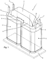
- An Indian FIG. 1 illustrated electromagnet 1 is exemplified as an arrangement of two wire coils 2, 3 formed on a common, exemplified U-shaped, spool core 4.
- the electromagnet 1 provides a magnetic field, which can be used, for example, to move an armature plate 5 shown in dashed lines from a spaced apart from the electromagnet 1 rest position in an approximated to the electromagnet 1 functional position.
- the armature plate 5 may for example be coupled to a valve body of a fluid valve, not shown, to lift this valve body from a valve seat in a valve housing and thus to allow fluid flow from an input port of the valve housing past the valve seat to an outlet port of the valve housing.
- Each of the wire coils 2, 3 comprises a plurality of turns of a coil wire, not shown, in particular a copper enamel wire, which are accommodated on a bobbin 6, as in the Figures 3 . 4 and 6 is shown in different embodiments.
- the tasks of the bobbin 6 consist on the one hand in the support of the respective wire coil 2, 3.
- the bobbin 6 serves to maintain a minimum distance between the made of an electrically conductive material, in particular iron Coil core and the not shown turns of the wire coils 2 and 3.
- 6 metallic terminal pins 7 and metallic connecting bridges 8 are arranged on the bobbin, which are provided for electrical coupling of the wire coils 2, 3.
- the bobbin 6 is preferably made of an electrically insulating material, in particular of plastic. It is particularly preferably provided that the bobbin 6 is produced by the plastic injection molding process, wherein it can be provided in particular that the connecting pieces 7 and the connecting bridges 8 are inserted into a plastic injection mold prior to the production of the bobbin 6 and are overmoulded with the plastic of the bobbin 6 In order to avoid a separate assembly of these components.
- the bobbin 4 according to the FIG. 1 is exemplified integrally formed and points to the in the FIG. 1 indicated, according to the representation of FIG. 1 downwardly projecting U-legs 9, which pass through the wire spools 2, 3, each wells 10, which correspond to profiles described below in more detail on the bobbins 6 and in particular in the FIG. 5 are shown in more detail.
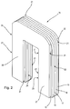
- the spool core 14 according to the FIG. 2 does not differ in its envelope geometry of the integrally formed spool core 4 according to the FIG. 1 , However, is formed from a plurality of parallel sheet metal layers 15 to 20, which are connected to each other for example cohesively.
- the metal layers 15 to 20 are provided on their respective largest surfaces with an insulating paint, not shown in more detail, and adhesively bonded to one another or connected to one another in a materially cohesive manner.
- the spool core 14 may alternatively be used for the spool core 4 to receive the respective wire spools 2, 3 and accordingly has recesses 21 on both the outer end faces 22, 23 and on the inner end faces 24, 25 of the U-legs 26, 27.
- Exemplary are the Recesses 21 formed by the respective outer sheet metal layers 15 and 20 have a smaller cross-section than the other sheet metal layers 16, 17, 18 and 19, so that between the sheet metal layers 15 and 20 and the remaining sheet metal layers 16, 17, 18 and 19 the recesses 21 form as recesses.
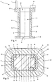
- FIG. 3 not shown wire coil between two exemplarily designed as a plane parallel plates with a substantially rectangular cross-section end pieces 28, 29 was added.
- the end pieces 28, 29 are aligned parallel to each other and are connected by two connecting webs 30, 31 with each other.
- each of the end pieces 28, 29 is penetrated by a recess 34, which determines the receiving space 11 and which is designed in an exemplary cuboid shape.
- the connecting webs 30, 31 In a cross-sectional plane, not shown, oriented normal to the winding axis 32, the connecting webs 30, 31 have the cross-section shown in dashed lines on the connecting web 31.
- the connecting webs 30, 31 are formed, for example, as plane-parallel plates, which has rounded corners 33 on an outwardly directed surface radially to the winding axis 32, in order to allow an advantageous deflection of the turns of the wire bobbin about the respective connecting webs 30, 31.
- a longitudinally extending along the winding axis 32 recess 41 provided with a rectangular cross section, which does not extend over the entire width of the connecting webs 30, 31, so that at outer edge regions of the connecting webs 30, 31 each profilings 35, 36, 37 and 38 are formed.
- these profilings 35, 36, 37 and 38 serve to engage in the depressions 10, 21 of the respective coil cores 4, 14 in order to provide an advantageous guidance between the respective coil core 4, 14 and the bobbin 6 during the assembly process to allow and thus avoid damage to the bobbin 6 mounted turns of the wire coils 2 and 3 respectively.
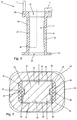
- a difference between a width dimension c of the recess 34 in the connecting webs 30, 31 and a width dimension d of a protrusion 39 is selected as a width dimension a of the connecting webs 30, 31 is larger than a width dimension b of the spool core on the spool core 4 and 14 chosen smaller than a difference in the width dimensions a and b, so that when inserting the respective spool core 4 or 14 in the bobbin 6 due to the leadership characteristics of the profiles 35, 36, 37 and 38, a mechanical contact between the Spool core 4 and 14 and the windings 40 of the wire coils 2 and 3 can be avoided.
- This embodiment of the connecting webs 30, 31 and the coil cores 4 and 14 can be an advantageous overall width e for the wire coils 2 and 3 achieve, so that in this spatial direction, a plurality of wire coils 2 and 3 adjacent to each other with the smallest possible pitch can be arranged.
- the in the FIGS. 6 and 7 shown bobbin 46 differs from the bobbin 6 in that the profilings 47, 48 are not arranged at the edge of the connecting webs 49, 50, but rather in a central region of the respective connecting webs 49, 50 are provided. Furthermore, the FIG. 6 can be seen that the profilings 47, 48 along the winding axis 32 have a variable profile height. By way of example, it is provided that the profiles 47, 48 in the cross-sectional view according to the FIG. 6 are each formed arcuate. In this case, the profilings 47, 48 protrude in a central region of the bobbin 46 particularly far inwardly into the receiving space 51, which for receiving a correspondingly adapted bobbin 52 according to the FIG. 7 is provided.
- end pieces 59, 60 of the bobbin 46 are each provided with a, in particular cuboid running, recess 61, which allows insertion of the bobbin 52 into the bobbin 46.
- the profilings 47, 48 are each formed on the basis of the end pieces 59, 60, wherein the recesses 61 determine, in regions, the receiving space 51 that is bounded in sections by the connecting webs 49, 50.
- the function of the profilings 47, 48 is in addition to the guide for the spool core 52 relative to the bobbin 46 in addition, that the bobbin 46 is bulged when receiving on a not shown, parallelepiped winding mandrel of a coil winding machine in the profiling 47, 48 to the outside ,
- the wire coil wound with a predetermined tensile force undergoes relaxation at least in the central region of the bobbin 46, resulting in a reduction of inwardly directed deformation forces on the wire bobbins 2 and 3, respectively the connecting webs 49, 50 follows.
- the profilings are realized in a similar manner with varying cross sections as is the case with the bobbin 46.
Landscapes
- Physics & Mathematics (AREA)
- Electromagnetism (AREA)
- Engineering & Computer Science (AREA)
- Power Engineering (AREA)
- Electromagnets (AREA)
Description
- Die Erfindung betrifft einen Elektromagneten mit wenigstens einer Drahtspule und einem wenigstens einem Spulenkern, wobei die wenigstens eine Drahtspule auf einem Spulenkörper aufgenommen ist und eine Vielzahl von Windungen umfasst, die den wenigstens einen Spulenkern umgeben und die eine Windungsachse bestimmen, wobei der wenigstens eine Spulenkörper längs der Windungsachse beabstandet angeordnete und die wenigstens eine Drahtspule axial begrenzende Endstücke umfasst, die durch wenigstens zwei längs der Windungsachse erstreckte Verbindungsstege miteinander verbunden sind und zusammen mit einer Ausnehmung in wenigstens einem der Endstücke einen Aufnahmeraum für den Spulenkern bestimmen.
- Aus der
EP 2 284 859 A1 ist ein Elektromagnet zur Verwendung in einem Relais bekannt, bei dem ein Spulenkörper endseitig mit Flanschabschnitten versehen ist, um eine Spule zu begrenzen und bei dem Windungen einer Spule einen Eisenkern umgeben, der mit einem endseitigen Flanschabschnitt versehen ist. Dabei sind der Spulenkörper und der Eisenkern derart aufeinander abgestimmt, dass der Eisenkern mit seinen Endbereichen jeweils über den Spulenkörper hinausragt, wobei ein Ende des Eisenkerns von einer Wickelmaschine zur Herstellung der Spule erfasst werden kann. Ferner sind die Flanschabschnitte des Spulenkörpers durch zwei Verbindungsstege mechanisch miteinander verbunden. - Dokument
JP S52 147250 U - Die Aufgabe der Erfindung besteht darin, einen Elektromagneten bereitzustellen, der eine einfache Montage und eine hohe Betriebssicherheit gewährleistet.
- Diese Aufgabe wird für einen Elektromagneten der eingangs genannten Art mit den Merkmalen des Anspruchs 1 gelöst. Hierbei ist vorgesehen, dass der Aufnahmeraum in einer normal zur Windungsachse ausgerichteten Querschnittsebene von einer rechteckigen Hüllkurve mit wenigstens einer nach innen ragenden Profilierung begrenzt ist und dass der wenigstens eine Spulenkern eine zumindest abschnittsweise längs der Windungsachse erstreckte und zur Profilierung korrespondierende Vertiefung aufweist.
- Vorzugsweise ist der Aufnahmeraum nur teilweise durch die Verbindungsstege und das wenigstens eine mit einer Ausnehmung versehene Endstück begrenzt und weist darüber hinaus auch Bereiche auf, die nicht vom Spulenkörper begrenzt sind, um eine kompakte Bauform des Elektromagneten zu gewährleisten. In diesen Bereichen ist dementsprechend ein unmittelbarer Kontakt zwischen den Windungen der Drahtspule, bei denen es sich beispielsweise um Windungen eines Kupferlackdrahts handeln kann, und dem typischerweise aus einem elektrisch leitenden, vorzugsweise ferritischen, Material hergestellten Spulenkern möglich. Um die gewünschte einfache Montage bei hoher Betriebssicherheit für den Elektromagneten gewährleisten zu können, ist in denjenigen Bereichen, in denen ein unmittelbarer Kontakt zwischen Drahtspule und Spulenkern stattfinden könnte, ein ausreichender Sicherheitsabstand zwischen der Drahtspule und dem Spulenkern vorzusehen. Um trotz dieses Sicherheitsabstands eine kompakte Bauform für den Elektromagneten gewährleisten zu können, sind der Spulenkörper und der Spulenkern mittels der Profilierungen und der korrespondierenden Vertiefungen aufeinander abgestimmt, dass bei einer Montage des Spulenkerns in den Aufnahmeraum des Spulenkörpers eine sichere Führung für die Spulenkern gewährleistet ist. Damit besteht trotz eines geringen Sicherheitsabstands des Spulenkerns gegenüber den Windungen der Drahtspule nicht die Gefahr, dass diese Windungen während des Montagevorgangs berührt werden und eine Isolationsschicht auf den Windungen, insbesondere eine Lackschicht, beschädigt wird. Die Profilierung im Aufnahmeraum des Spulenkörpers und die korrespondierende Vertiefung im Spulenkern stellen somit eine vorteilhafte Schiebeführung während des Einschiebens des Spulenkerns in den Spulenkörper sicher. Die Profilierung im Aufnahmeraum des Spulenkörpers kann sich abschnittsweise längs der Windungsachse erstrecken oder über die gesamte Länge der Windungsachse ausgedehnt sein. Die Vertiefung im Spulenkern muss so ausgebildet sein, dass sie ein Einschieben des Spulenkerns in den Aufnahmeraum ermöglicht. Je nach Ausgestaltung der Profilierung am Spulenkörper erstreckt sich somit die Vertiefung am Spulenkern wahlweise über einen Teilbereich der Windungsachse oder längs der gesamten Windungsachse über die Länge des Spulenkörpers in Richtung der Windungsachse.
- Vorteilhafte Weiterbildungen der Erfindung sind in den Unteransprüchen angegeben.
- Zweckmäßig ist es, wenn die Profilierung an einer dem wenigstens einen Spulenkern gegenüberliegenden Oberfläche des Verbindungsstücks ausgebildet ist. Hierdurch werden die Führungseigenschaften für die Montage des Spulenkerns in den Spulenkörper in besonders vorteilhafter Weise sichergestellt. Vorzugsweise erstreckt sich die Profilierung längs der gesamten Ausdehnung des Verbindungsstegs in Richtung der Windungsachse. Alternativ kann vorgesehen sein, dass die Profilierung abschnittsweise unterbrochen ausgebildet ist, um zumindest bei größeren Spulenkörpern eine Material- und Gewichtsersparnis erzielen zu können. In der Regel wird sich die Profilierung jedoch zumindest nahezu vollständig längs der Windungsachse am Verbindungsstück erstrecken. Besonders bevorzugt sind die Profilierungen und die Vertiefungen spiegelsymmetrisch zu einer die Windungsachse umfassenden Spiegelebene angeordnet.
- Vorteilhaft ist es, wenn die Profilierung an einer dem wenigstens einen Spulenkern gegenüberliegenden Oberfläche der Ausnehmung des Endstücks ausgebildet ist. Hierdurch kann erreicht werden, dass bereits bei Beginn des Montagevorgangs während des Einschiebens des Spulenkerns in den Spulenkörper von vornherein die gewünschte Führung des Spulenkerns durch die Wechselwirkung von Profilierung und Vertiefung gewährleistet ist. Besonders vorteilhaft ist es, wenn sich an die Profilierung in der Ausnehmung des Endstücks eine Profilierung an der dem Spulenkern gegenüberliegenden Oberfläche des Verbindungsstücks anschließt, um somit eine besonders sichere Führung des Spulenkerns gewährleisten zu können.
- Bei einer vorteilhaften Weiterbildung der Erfindung ist vorgesehen, dass genau zwei Verbindungsstege zwischen den Endstücken angeordnet sind, die einander gegenüberliegende Seitenflächen des Aufnahmeraums bilden. Mit den zwei Verbindungsstegen kann bereits eine formstabile Ausgestaltung des Spulenkörpers bei geringem Materialeinsatz erzielt werden. Vorzugsweise sind die Verbindungsstege symmetrisch zur Windungsachse ausgerichtet und im Wesentlichen plattenförmig ausgestaltet.
- In weiterer Ausgestaltung der Erfindung ist vorgesehen, dass jeder Verbindungssteg zwei längs der Windungsachse erstreckte Randbereiche umfasst, die jeweils mit einer Profilierung versehen sind und in Eckbereichen der Hüllkurve angeordnet sind. Durch die Anordnung der Profilierungen in den Randbereichen der Verbindungsstege, die gleichzeitig in den Eckbereichen der Hüllkurve angeordnet sind, bilden die Profilierungen einen Kantenschutz. Dieser Kantenschutz gewährleistet in den ohnehin besonders kritischen Eckbereichen eine zuverlässige Beabstandung zwischen den Windungen der Drahtspule und dem Spulenkern, wodurch die gewünschte hohe Betriebssicherheit und Montagefreundlichkeit gewährleistet wird. Zwar wird ein Querschnitt des Spulenkerns in einer normal zur Windungsachse ausgerichteten Querschnittsebene durch die zur Aufnahme der Profilierungen am Spulenkörper notwendigen Vertiefungen reduziert. Dieser nominale Nachteil für die Flussleiteigenschaften des Spulenkerns wird jedoch durch die verringerten Sicherheitsabstände zwischen Drahtspule und Spulenkern, die auf Grund der Schutzwirkung der Profilierungen reduziert werden können, zumindest im Wesentlichen kompensiert oder vorzugsweise überkompensiert.
- Bei einer alternativen Ausführungsform des Spulenkörpers ist vorgesehen, dass genau vier Verbindungsstege zwischen den Endstücken ausgebildet sind, wobei die Verbindungsstege jeweils als Profilierung ausgebildet und in Eckbereichen der rechteckigen Hüllkurve angeordnet sind. Eine derartige Gestaltung des Spulenkörpers erlaubt einen minimalen Materialeinsatz bei der Herstellung des Spulenkörpers, ohne auf den Kantenschutz für die Windungen der Drahtspule verzichten zu müssen.
- Bei einer vorteilhaften Weiterbildung ist vorgesehen, dass wenigstens eine Profilierung einen längs der Wickelachse variierenden Querschnitt aufweist. Vorzugsweise ist vorgesehen, dass die Profilierung in einem zentralen Bereich des Spulenkörpers am stärksten ausgeprägt ist und somit um den größten Betrag nach innen in den Aufnahmeraum ragt und zu den Endstücken hin abgeflacht ist. Dieser, insbesondere bogenförmige, Verlauf für die wenigstens eine Profilierung längs der Wickelachse führt bei Aufnahme des Spulenkörpers auf einen beispielsweise quaderförmig ausgebildeten Wickeldorn zu einer Deformation des Spulenkörpers in eine Radialrichtung quer zur Windungsachse. Im zentralen Bereich des Spulenkörpers, wo die höchste Elastizität der Verbindungsstege vorliegt, resultiert daher eine aufgrund der Profilierung folgende geringfügige Auswölbung des Spulenkörpers und der darauf zu wickelnden Drahtspule. Nach Abnehmen vom Wickelkörper liegt in diesem Bereich somit eine geringfügig reduzierte innere Spannung der Drahtspule vor, so dass die Verbindungsstege in diesem Bereich weniger belastet werden als in den Bereichen nahe der Endstücke, wo eine höhere Steifigkeit der Verbindungsstege gegeben ist.
- Bei einer vorteilhaften Weiterbildung der Erfindung ist vorgesehen, dass der Spulenkern aus mehreren, zueinander parallelen Blechlagen ausgebildet ist und dass die Vertiefungen als Ausnehmungen oder Rücksprünge an den Blechlagen ausgebildet sind. Durch die Ausgestaltung des Spulenkerns aus mehreren Blechlagen sollen Wirbelströme im Spulenkern verhindert werden, wodurch dessen Flusseigenschaften für das zu leitende Magnetfeld verbessert werden. Ferner können die einzelnen Blechlagen in ihrer Geometrie derart gestaltet werden, dass sich durch die Aufschichtung der Blechlagen zum Spulenkern die benötigten Vertiefungen bilden, ohne dass eine diesbezügliche zusätzliche Bearbeitung des Spulenkerns erforderlich ist.
- Vorteilhafte Ausführungsformen der Erfindung sind in der Zeichnung dargestellt. Dabei zeigt:
-
Figur 1 eine perspektivische Darstellung eines Elektromagneten mit zwei Drahtspulen, -
Figur 2 eine Ausführungsform eines Spulenkerns, der aus mehreren, zueinander parallelen Blechlagen gebildet ist, -
Figur 3 eine perspektivische Darstellung einer ersten Ausführungsform eines Spulenkörpers, -
Figur 4 eine seitliche Schnittdarstellung des Spulenkörpers gemäß derFigur 3 , -
Figur 5 eine Schnittdarstellung eines Elektromagneten mit dem Spulenkörper gemäß denFiguren 3 und4 , -
Figur 6 eine zweite Ausführungsform eines Spulenkörpers mit einer Profilierung, deren Querschnitt längs der Windungsachse variiert und -
Figur 7 einen Querschnitt eines Elektromagneten mit dem Spulenkörper gemäß derFigur 6 . - Ein in der
Figur 1 dargestellter Elektromagnet 1 ist exemplarisch als Anordnung von zwei Drahtspulen 2, 3 auf einem gemeinsamen, exemplarisch U-förmig gestalteten, Spulenkern 4 ausgebildet. Bei Anlegen eines elektrischen Stroms an die Drahtspulen 2, 3 stellt der Elektromagnet 1 ein Magnetfeld bereit, das beispielsweise zur Bewegung einer gestrichelt dargestellten Ankerplatte 5 aus einer beabstandet zum Elektromagneten 1 angeordneten Ruhestellung in eine an den Elektromagneten 1 angenäherte Funktionsstellung genutzt werden kann. Die Ankerplatte 5 kann beispielsweise mit einem Ventilkörper eines nicht näher dargestellten Fluidventils gekoppelt sein, um diesen Ventilkörper von einem Ventilsitz in einem Ventilgehäuse abzuheben und somit einen Fluidstrom von einem Eingangsanschluss des Ventilgehäuses am Ventilsitz vorbei zu einem Ausgangsanschluss des Ventilgehäuses zu ermöglichen. - Jede der Drahtspulen 2, 3 umfasst eine Vielzahl von Windungen eines nicht näher dargestellten Spulendrahts, insbesondere eines Kupfer-Lackdrahts, die an einem Spulenkörper 6 aufgenommen sind, wie er in den
Figuren 3 ,4 und6 in unterschiedlichen Ausführungsformen dargestellt ist. Die Aufgaben des Spulenkörpers 6 bestehen zum einen in der Abstützung der jeweiligen Drahtspule 2, 3. Ferner dient der Spulenkörper 6 zur Einhaltung eines Mindestabstands zwischen dem aus einem elektrisch leitfähigen Material, insbesondere Eisen, hergestellten Spulenkern und den nicht näher dargestellten Windungen der Drahtspulen 2 bzw. 3. Darüber hinaus sind am Spulenkörper 6 metallische Anschlussstifte 7 sowie metallische Verbindungsbrücken 8 angeordnet, die für eine elektrische Ankopplung der Drahtspulen 2, 3 vorgesehen sind. Um eine elektrische Isolation für die Anschlussstücke 7 und die Verbindungsbrücken 8 zu gewährleisten, ist der Spulenkörper 6 vorzugsweise aus einem elektrisch isolierenden Material, insbesondere aus Kunststoff, hergestellt. Besonders bevorzugt ist vorgesehen, dass der Spulenkörper 6 im Kunststoff-Spritzgussverfahren hergestellt ist, wobei insbesondere vorgesehen sein kann, dass die Anschlussstücke 7 und die Verbindungsbrücken 8 vor der Herstellung des Spulenkörpers 6 in eine Kunststoffspritzgussform eingelegt werden und mit dem Kunststoff des Spulenkörpers 6 umspritzt werden, um eine separate Montage dieser Komponenten vermeiden zu können. - Der Spulenkern 4 gemäß der
Figur 1 ist exemplarisch einstückig ausgebildet und weist an den in derFigur 1 angedeuteten, gemäß der Darstellung derFigur 1 nach unten ragenden U-Schenkeln 9, die die Drahtspulen 2, 3 durchsetzen, jeweils Vertiefungen 10 auf, die zu nachstehend näher beschriebenen Profilierungen an den Spulenkörpern 6 korrespondieren und die insbesondere in derFigur 5 näher dargestellt sind. - Der Spulenkern 14 gemäß der
Figur 2 unterscheidet sich in seiner Hüllgeometrie nicht von dem einstückig ausgebildeten Spulenkern 4 gemäß derFigur 1 , ist jedoch aus einer Vielzahl von parallelen Blechlagen 15 bis 20 gebildet, die beispielsweise stoffschlüssig miteinander verbunden sind. Exemplarisch sind die Blechlagen 15 bis 20 an ihren jeweils größten Oberflächen mit einer nicht näher dargestellten, isolierenden Lackierung versehen und miteinander verklebt oder in anderer Weise stoffschlüssig miteinander verbunden. Der Spulenkern 14 kann alternativ zum Spulenkern 4 eingesetzt werden, um jeweils die Drahtspulen 2, 3 aufzunehmen und weist dementsprechend Vertiefungen 21 sowohl an den äußeren Stirnseiten 22, 23 als auch an den inneren Stirnseiten 24, 25 der U-Schenkel 26, 27 auf. Exemplarisch werden die Vertiefungen 21 dadurch gebildet, dass die jeweils außen liegenden Blechlagen 15 und 20 einen geringeren Querschnitt als die übrigen Blechlagen 16, 17, 18 und 19 aufweisen, so dass sich zwischen den Blechlagen 15 und 20 und den übrigen Blechlagen 16, 17, 18 und 19 die Vertiefungen 21 als Rücksprünge ausbilden. - Bei der in den
Figuren 3 und4 dargestellten ersten Ausführungsform des Spulenkörpers 6, wie sie aus derFigur 1 bekannt ist, wird die inFigur 3 nicht dargestellte Drahtspule zwischen zwei exemplarisch als Planparallelplatten mit im Wesentlichen rechteckigem Querschnitt ausgebildeten Endstücken 28, 29 aufgenommen. Die Endstücke 28, 29 sind parallel zueinander ausgerichtet und werden durch zwei Verbindungsstege 30, 31 miteinander verbunden. Exemplarisch wird jedes der Endstücke 28, 29 von einer Ausnehmung 34 durchsetzt, die den Aufnahmeraum 11 mitbestimmt und die exemplarisch quaderförmig ausgebildet ist. - In einer nicht dargestellten, normal zur Windungsachse 32 ausgerichteten Querschnittsebene weisen die Verbindungsstege 30, 31 den am Verbindungssteg 31 gestrichelt dargestellten Querschnitt auf. Die Verbindungsstege 30, 31 sind beispielsweise als Planparallelplatten ausgebildet, die an einer nach außen gerichteten Oberfläche radial zur Windungsachse 32 abgerundete Ecken 33 aufweist, um eine vorteilhafte Umlenkung der Windungen der Drahtspule um die jeweiligen Verbindungsstege 30, 31 zu ermöglichen. Ferner ist an einer Innenseite der Verbindungsstege 30, 31 eine längs der Windungsachse 32 erstreckte Ausnehmung 41 mit rechteckigem Querschnitt vorgesehen, die sich nicht über die gesamte Breite der Verbindungsstege 30, 31 erstreckt, so dass an außen liegenden Randbereichen der Verbindungsstege 30, 31 jeweils Profilierungen 35, 36, 37 und 38 ausgebildet werden. Diese Profilierungen 35, 36, 37 und 38 ermöglichen einerseits die starke Verrundung der abgerundeten Ecken 33. Andererseits dienen diese Profilierungen 35, 36, 37 und 38 zum Eingriff in die Vertiefungen 10, 21 der jeweiligen Spulenkerne 4, 14, um eine vorteilhafte Führung zwischen dem jeweiligen Spulenkern 4, 14 und dem Spulenkörper 6 während des Montagevorgangs zu ermöglichen und damit eine Beschädigung der am Spulenkörper 6 angebrachten Windungen der Drahtspulen 2 bzw. 3 zu vermeiden.
- Wie aus der
Figur 5 entnommen werden kann, ist ein Breitenmaß a der Verbindungsstege 30, 31 größer gewählt als ein Breitenmaß b des Spulenkerns 4 bzw. 14. Ferner ist eine Differenz zwischen einem Breitenmaß c der Ausnehmung 34 in den Verbindungsstegen 30, 31 und einem Breitenmaß d eines Vorsprungs 39 am Spulenkern 4 bzw. 14 kleiner gewählt als eine Differenz der Breitenmaße a und b, so dass beim Einschieben des jeweiligen Spulenkerns 4 bzw. 14 in den Spulenkörper 6 auf Grund der Führungseigenschaften der Profilierungen 35, 36, 37 und 38 ein mechanischer Kontakt zwischen dem Spulenkern 4 bzw. 14 und den Windungen 40 der Drahtspulen 2 bzw. 3 vermieden werden kann. Durch diese Ausgestaltung der Verbindungsstege 30, 31 und der Spulenkerne 4 bzw. 14 lässt sich eine vorteilhafte Gesamtbreite e für die Drahtspulen 2 bzw. 3 erzielen, so dass in dieser Raumrichtung eine Vielzahl von Drahtspulen 2 bzw. 3 mit einem möglichst geringen Rastermaß zueinander benachbart angeordnet werden können. - Der in den
Figuren 6 und 7 dargestellte Spulenkörper 46 unterscheidet sich vom Spulenkörper 6 dadurch, dass die Profilierungen 47, 48 an den Verbindungsstegen 49, 50 nicht randseitig angeordnet sind, sondern vielmehr in einem zentralen Bereich der jeweiligen Verbindungsstege 49, 50 vorgesehen sind. Ferner ist derFigur 6 zu entnehmen, dass die Profilierungen 47, 48 längs der Windungsachse 32 eine variable Profilhöhe aufweisen. Exemplarisch ist vorgesehen, dass die Profilierungen 47, 48 in der Querschnittsdarstellung gemäß derFigur 6 jeweils bogenförmig ausgebildet sind. Dabei ragen die Profilierungen 47, 48 in einem zentralen Bereich des Spulenkörpers 46 besonders weit nach innen in den Aufnahmeraum 51 hinein, der zur Aufnahme eines entsprechend angepassten Spulenkerns 52 gemäß derFigur 7 vorgesehen ist. Durch diese Profilierungen 47, 48 und die korrespondierenden, insbesondere geometrisch ähnlichen, Vertiefungen 53, 54 im Spulenkern 52 wird in ähnlicher Weise wie beim Spulenkörper 6 und den dafür vorgesehenen Spulenkernen 4, 14 eine Zwangsführung zwischen Spulenkörper 46 und Spulenkern 52 bei der Montage dieser Komponenten relativ zueinander ermöglicht. Somit können Sicherheitsabstände f und g zwischen Außenflächen 55, 56 des Spulenkerns 52 und Innenflächen 57, 58 der Drahtspulen 2 bzw. 3 zur Verwirklichung einer schmalen Bauweise für den Elektromagneten gewählt werden. - Exemplarisch ist vorgesehen, dass Endstücke 59, 60 des Spulenkörpers 46 jeweils mit einer, insbesondere quaderförmig ausgeführten, Ausnehmung 61 versehen sind, die ein Einschieben des Spulenkerns 52 in den Spulenkörper 46 ermöglicht. Ferner ist beispielhaft vorgesehen, dass die Profilierungen 47, 48 jeweils ausgehend von den Endstücken 59, 60 ausgebildet sind, wobei die Ausnehmungen 61 bereichsweise den im Übrigen abschnittsweise von den Verbindungsstegen 49, 50 begrenzten Aufnahmeraum 51 bestimmen.
- Aus den Darstellungen der
Figuren 5 und7 ist zu entnehmen, dass die Querschnitte der von den jeweiligen Spulenkörpern 6, 46 gebildeten Aufnahmeräume 11, 51 jeweils mittels einer gestrichelt und aus Darstellungsgründen leicht vergrößert eingezeichneten, rechteckigen Hüllkurve 12 bzw. 62 beschrieben werden können, in die die jeweiligen Profilierungen 35, 36, 37 und 38 bzw. 47 und 48 hineinragen. Ferner ist diesen Figuren auch zu entnehmen, dass die Spulenkerne 4 bzw. 14 und 52 ebenfalls einen im Wesentlichen rechteckigen Querschnitt aufweisen, der lediglich durch die zur Aufnahme der Profilierungen 35, 36, 37 und 38 bzw. 47 und 48 notwendigen Vertiefungen 10, 53 lokal verändert wird. - Die Funktion der Profilierungen 47, 48 besteht neben der Führung für den Spulenkern 52 gegenüber dem Spulenkörper 46 zusätzlich darin, dass der Spulenkörper 46 bei Aufnahme auf einen nicht näher dargestellten, quaderförmig ausgebildeten Wickeldorn einer Spulenwickelmaschine im Bereich der Profilierungen 47, 48 nach außen aufgewölbt wird. Somit erfährt die mit einer vorgegebenen Zugkraft gewickelte Drahtspule nach Abnehmen vom Wickeldorn zumindest im zentralen Bereich des Spulenkörpers 46 eine Entspannung, woraus eine Reduktion von nach innen gerichteten Deformationskräften von den Drahtspulen 2 bzw. 3 auf die Verbindungsstege 49, 50 folgt. Hierdurch wird eine einfache Montage des Spulenkerns 52 ermöglicht und gegebenenfalls sogar ein Kollabieren der Verbindungsstege 49, 50 verhindert. Ferner wird durch die Profilierungen 35, 36, 37 und 38 bzw. 47 und 48 eine Versteifung der jeweiligen Verbindungsstege 30, 31 bzw. 49 und 50 erreicht, so dass ohne eine erhebliche Beeinflussung des freien Querschnitts des Aufnahmeraums 11, 51 eine erhebliche Stabilisierungswirkung erzielt werden kann.
- Bei einer nicht dargestellten Variante des Spulenkörpers 6 sind die Profilierungen in ähnlicher Weise mit variierenden Querschnitten verwirklicht wie dies beim Spulenkörper 46 der Fall ist.
Claims (8)
- Elektromagnet mit wenigstens einer Drahtspule (2, 3) und wenigstens einem Spulenkern (4; 14; 52), wobei die wenigstens eine Drahtspule (2, 3) auf einem Spulenkörper (6; 46) aufgenommen ist und eine Vielzahl von Windungen (40) umfasst, die den wenigstens einen Spulenkern (4; 14; 52) umgeben und die eine Windungsachse (32) bestimmen, wobei der Spulenkörper (6; 46) längs der Windungsachse (32) beabstandet angeordnete und die wenigstens eine Drahtspule (2, 3) axial begrenzende Endstücke (28, 39; 59, 60) umfasst, die durch wenigstens zwei längs der Windungsachse (32) erstreckte Verbindungsstege (30, 31; 49, 50) miteinander verbunden sind und zusammen mit einer Ausnehmung (41; 61) in wenigstens einem der Endstücke (28, 29; 59, 60) einen Aufnahmeraum (11; 51) für den wenigstens einen Spulenkern (4; 14; 52) bestimmen, wobei der Aufnahmeraum (11; 51) in einer normal zur Windungsachse (32) ausgerichteten Querschnittsebene von einer rechteckigen Hüllkurve (12; 62) mit wenigstens einer nach innen ragenden Profilierung (35, 36, 37, 38; 47, 48) begrenzt ist, dadurch gekennzeichnet, dass der wenigstens eine Spulenkern (4; 14; 52) eine zumindest abschnittsweise längs der Windungsachse (32) erstreckte und zur Profilierung (35, 36, 37, 38; 47, 48) korrespondierende Vertiefung (10, 21; 53, 54) aufweist.
- Elektromagnet nach Anspruch 1, dadurch gekennzeichnet, dass die Profilierung (35, 36, 37, 38; 47, 48) an einer dem wenigstens einen Spulenkern (4; 14; 52) gegenüberliegenden Oberfläche des Verbindungsstegs (30, 31; 49, 50) ausgebildet ist.
- Elektromagnet nach Anspruch 1 oder 2, dadurch gekennzeichnet, dass die Profilierung (35, 36, 37, 38; 47, 48) an einer dem wenigstens einen Spulenkern (4; 14; 52) gegenüberliegenden Oberfläche der Ausnehmung des Endstücks (28, 29) ausgebildet ist.
- Elektromagnet nach Anspruch 1, 2 oder 3, dadurch gekennzeichnet, dass genau zwei Verbindungsstege (30, 31; 49, 50) zwischen den Endstücken (28, 29) angeordnet sind, die einander gegenüberliegende Seitenflächen des Aufnahmeraums (11; 51) bilden.
- Elektromagnet nach Anspruch 4, dadurch gekennzeichnet, dass jeder Verbindungssteg (30, 31; 49, 50) zwei längs der Windungsachse (32) erstreckte Randbereiche umfasst, die jeweils mit einer Profilierung (35, 36, 37, 38) versehen sind und in Eckbereichen der Hüllkurve (12) angeordnet sind.
- Elektromagnet nach Anspruch 1, 2 oder 3, dadurch gekennzeichnet, dass genau vier Verbindungsstege zwischen den Endstücken ausgebildet sind, wobei die Verbindungsstege jeweils als Profilierung ausgebildet und in Eckbereichen der rechteckigen Hüllkurve angeordnet sind.
- Elektromagnet nach einem der vorhergehenden Ansprüche, dadurch gekennzeichnet, dass wenigstens eine Profilierung (47, 48) einen längs der Wickelachse (32) variierenden Querschnitt aufweist.
- Elektromagnet nach einem der vorhergehenden Ansprüche, dadurch gekennzeichnet, dass der wenigstens eine Spulenkern (14) aus mehreren, zueinander parallelen Blechlagen (15, 16, 17, 18, 19, 20) ausgebildet ist und dass die Vertiefungen (21) als Ausnehmungen oder Rücksprünge an den Blechlagen (15, 16, 17, 18, 19, 20) ausgebildet sind.
Applications Claiming Priority (2)
| Application Number | Priority Date | Filing Date | Title |
|---|---|---|---|
| DE102014005437.3A DE102014005437A1 (de) | 2014-04-11 | 2014-04-11 | Elektromagnet |
| PCT/EP2015/056947 WO2015155052A1 (de) | 2014-04-11 | 2015-03-31 | Elektromagnet |
Publications (2)
| Publication Number | Publication Date |
|---|---|
| EP3129992A1 EP3129992A1 (de) | 2017-02-15 |
| EP3129992B1 true EP3129992B1 (de) | 2018-05-02 |
Family
ID=52781088
Family Applications (1)
| Application Number | Title | Priority Date | Filing Date |
|---|---|---|---|
| EP15713473.5A Active EP3129992B1 (de) | 2014-04-11 | 2015-03-31 | Elektromagnet |
Country Status (4)
| Country | Link |
|---|---|
| US (1) | US9697942B2 (de) |
| EP (1) | EP3129992B1 (de) |
| DE (1) | DE102014005437A1 (de) |
| WO (1) | WO2015155052A1 (de) |
Families Citing this family (3)
| Publication number | Priority date | Publication date | Assignee | Title |
|---|---|---|---|---|
| US9991045B1 (en) * | 2014-11-04 | 2018-06-05 | Universal Lighting Technologies, Inc. | Bobbin and core assembly configuration and method for E-core and I-core combination |
| JP7017076B2 (ja) * | 2017-12-25 | 2022-02-08 | トヨタ自動車株式会社 | リアクトル |
| CA3184244A1 (en) | 2020-06-24 | 2021-12-30 | Bernhard Spiegl | Solenoid valve |
Family Cites Families (16)
| Publication number | Priority date | Publication date | Assignee | Title |
|---|---|---|---|---|
| CH134181A (de) * | 1928-05-12 | 1929-07-15 | Winiger Arthur | Transformator mit Ölumlauf. |
| DE728288C (de) * | 1938-07-29 | 1942-11-24 | Heliowatt Werke Elek Zitaets A | Hochfrequenzspule mit einschraubbarem Eisenkern |
| DE1076806B (de) * | 1956-09-19 | 1960-03-03 | Rudolf Zur Bonsen Fa | Transformator fuer kurze Spannungsstoesse sehr hoher Intensitaet |
| AT237149B (de) * | 1961-04-28 | 1964-11-25 | Landis & Gyr Ag | Hülsenförmiger Spulenkörper aus elastischem Isoliermaterial für elektrische Spulen |
| JPS52147250U (de) * | 1976-04-30 | 1977-11-08 | ||
| JPS52147250A (en) | 1976-06-01 | 1977-12-07 | Mitsubishi Electric Corp | Tilting pad thrust bearing |
| DE2627314C2 (de) * | 1976-06-18 | 1982-10-21 | Transformatoren Union Ag, 7000 Stuttgart | Wicklung für Transformatoren |
| DE2717081A1 (de) * | 1977-04-18 | 1978-11-09 | Bbc Brown Boveri & Cie | Spulenkoerper |
| DE2931362A1 (de) * | 1979-08-02 | 1981-02-19 | Philips Patentverwaltung | Vorrichtung zum bewickeln von geschlossenen ringkernen |
| US5034716A (en) * | 1989-11-08 | 1991-07-23 | Sundstrand Corporation | Radial cooled autotransformer assembly |
| DE4203199C3 (de) * | 1992-02-05 | 2000-10-26 | Loewe Opta Gmbh | Bauelement |
| DE102006019296A1 (de) * | 2006-04-26 | 2007-10-31 | Robert Bosch Gmbh | Zündspule, insbesondere für eine Brennkraftmaschine eines Kraftfahrzeugs |
| JP4803206B2 (ja) | 2008-04-24 | 2011-10-26 | パナソニック電工株式会社 | リレー用電磁石 |
| DE202011102342U1 (de) * | 2011-06-22 | 2011-08-08 | Preventive Medical Health Care Co., Ltd. | Magnetkörper |
| DE102011079667A1 (de) * | 2011-07-22 | 2013-01-24 | SUMIDA Components & Modules GmbH | Längenvariabler Spulenkörper und induktives Bauelement |
| DE102012205116A1 (de) * | 2012-03-29 | 2013-10-02 | Robert Bosch Gmbh | Zündspule mit verbesserten Imprägniereigenschaften |
-
2014
- 2014-04-11 DE DE102014005437.3A patent/DE102014005437A1/de not_active Ceased
-
2015
- 2015-03-31 WO PCT/EP2015/056947 patent/WO2015155052A1/de not_active Ceased
- 2015-03-31 US US15/302,336 patent/US9697942B2/en active Active
- 2015-03-31 EP EP15713473.5A patent/EP3129992B1/de active Active
Non-Patent Citations (1)
| Title |
|---|
| None * |
Also Published As
| Publication number | Publication date |
|---|---|
| WO2015155052A1 (de) | 2015-10-15 |
| US9697942B2 (en) | 2017-07-04 |
| US20170025211A1 (en) | 2017-01-26 |
| EP3129992A1 (de) | 2017-02-15 |
| DE102014005437A1 (de) | 2015-10-15 |
Similar Documents
| Publication | Publication Date | Title |
|---|---|---|
| EP2745383B1 (de) | Wicklungsträger zur verwendung in einer elektrischen maschine sowie wicklungsanordnung | |
| DE102015208210A1 (de) | Elektronisch kommutierter Gleichstrommotor | |
| WO2008113086A2 (de) | Verfahren zum maschinellen wickeln einer spule | |
| EP2551679A2 (de) | Stromsensoranordnung | |
| DE3200014A1 (de) | Hubmagnet-betaetigungseinrichtung | |
| DE112019003786T5 (de) | Stator und sich drehende Elektromaschine | |
| DE102020100514A1 (de) | Isolator | |
| DE102019104514A1 (de) | Elektromagnetische Vorrichtung | |
| WO2015155052A1 (de) | Elektromagnet | |
| EP3726651B1 (de) | Antenne | |
| EP2551678B1 (de) | Stromsensoranordnung | |
| WO2019038349A1 (de) | Ringkernbaugruppe, stromkompensierte drossel und verfahren zur herstellung einer ringkernbaugruppe | |
| EP2549493B1 (de) | Längenvariabler Spulenkörper und induktives Bauelement | |
| EP1444158B1 (de) | Wickelspule | |
| DE102013113244A1 (de) | Spule für ein induktives Energieübertragungssystem | |
| DE102017114092A1 (de) | Spulenvorrichtung | |
| DE102013216207A1 (de) | Verbesserter Wärmeübergang durch optimierten Blechschnitt eines Statorblechs eines Stators für einen Elektromotor | |
| EP2551680A2 (de) | Stromsensoranordnung | |
| DE102015006517A1 (de) | Ventilmagnetschalter | |
| EP3360145B1 (de) | Stabförmiges induktivbauteil | |
| DE102004008961B4 (de) | Spulenkörper für geschlossenen magnetischen Kern und daraus hergestellte Entstördrossel | |
| DE102011018167B4 (de) | Induktiver Näherungs- oder Abstandssensor | |
| EP3224841B1 (de) | Hochspannungstransformator mit u-förmigem kern | |
| DE9015849U1 (de) | Ferritkern | |
| DE4036275A1 (de) | Ringfoermiger spulenkoerper fuer klein- und sicherheitstranformatoren und verfahren zu seiner herstellung |
Legal Events
| Date | Code | Title | Description |
|---|---|---|---|
| STAA | Information on the status of an ep patent application or granted ep patent |
Free format text: STATUS: THE INTERNATIONAL PUBLICATION HAS BEEN MADE |
|
| PUAI | Public reference made under article 153(3) epc to a published international application that has entered the european phase |
Free format text: ORIGINAL CODE: 0009012 |
|
| STAA | Information on the status of an ep patent application or granted ep patent |
Free format text: STATUS: REQUEST FOR EXAMINATION WAS MADE |
|
| 17P | Request for examination filed |
Effective date: 20160920 |
|
| AK | Designated contracting states |
Kind code of ref document: A1 Designated state(s): AL AT BE BG CH CY CZ DE DK EE ES FI FR GB GR HR HU IE IS IT LI LT LU LV MC MK MT NL NO PL PT RO RS SE SI SK SM TR |
|
| AX | Request for extension of the european patent |
Extension state: BA ME |
|
| RIN1 | Information on inventor provided before grant (corrected) |
Inventor name: BUEHLER, ANDREAS |
|
| DAV | Request for validation of the european patent (deleted) | ||
| DAX | Request for extension of the european patent (deleted) | ||
| GRAP | Despatch of communication of intention to grant a patent |
Free format text: ORIGINAL CODE: EPIDOSNIGR1 |
|
| STAA | Information on the status of an ep patent application or granted ep patent |
Free format text: STATUS: GRANT OF PATENT IS INTENDED |
|
| INTG | Intention to grant announced |
Effective date: 20171218 |
|
| GRAS | Grant fee paid |
Free format text: ORIGINAL CODE: EPIDOSNIGR3 |
|
| GRAA | (expected) grant |
Free format text: ORIGINAL CODE: 0009210 |
|
| STAA | Information on the status of an ep patent application or granted ep patent |
Free format text: STATUS: THE PATENT HAS BEEN GRANTED |
|
| AK | Designated contracting states |
Kind code of ref document: B1 Designated state(s): AL AT BE BG CH CY CZ DE DK EE ES FI FR GB GR HR HU IE IS IT LI LT LU LV MC MK MT NL NO PL PT RO RS SE SI SK SM TR |
|
| REG | Reference to a national code |
Ref country code: GB Ref legal event code: FG4D Free format text: NOT ENGLISH |
|
| REG | Reference to a national code |
Ref country code: CH Ref legal event code: EP Ref country code: AT Ref legal event code: REF Ref document number: 996094 Country of ref document: AT Kind code of ref document: T Effective date: 20180515 |
|
| REG | Reference to a national code |
Ref country code: DE Ref legal event code: R096 Ref document number: 502015004136 Country of ref document: DE |
|
| REG | Reference to a national code |
Ref country code: IE Ref legal event code: FG4D Free format text: LANGUAGE OF EP DOCUMENT: GERMAN |
|
| REG | Reference to a national code |
Ref country code: NL Ref legal event code: MP Effective date: 20180502 |
|
| REG | Reference to a national code |
Ref country code: LT Ref legal event code: MG4D |
|
| PG25 | Lapsed in a contracting state [announced via postgrant information from national office to epo] |
Ref country code: BG Free format text: LAPSE BECAUSE OF FAILURE TO SUBMIT A TRANSLATION OF THE DESCRIPTION OR TO PAY THE FEE WITHIN THE PRESCRIBED TIME-LIMIT Effective date: 20180802 Ref country code: NO Free format text: LAPSE BECAUSE OF FAILURE TO SUBMIT A TRANSLATION OF THE DESCRIPTION OR TO PAY THE FEE WITHIN THE PRESCRIBED TIME-LIMIT Effective date: 20180802 Ref country code: FI Free format text: LAPSE BECAUSE OF FAILURE TO SUBMIT A TRANSLATION OF THE DESCRIPTION OR TO PAY THE FEE WITHIN THE PRESCRIBED TIME-LIMIT Effective date: 20180502 Ref country code: SE Free format text: LAPSE BECAUSE OF FAILURE TO SUBMIT A TRANSLATION OF THE DESCRIPTION OR TO PAY THE FEE WITHIN THE PRESCRIBED TIME-LIMIT Effective date: 20180502 Ref country code: ES Free format text: LAPSE BECAUSE OF FAILURE TO SUBMIT A TRANSLATION OF THE DESCRIPTION OR TO PAY THE FEE WITHIN THE PRESCRIBED TIME-LIMIT Effective date: 20180502 Ref country code: LT Free format text: LAPSE BECAUSE OF FAILURE TO SUBMIT A TRANSLATION OF THE DESCRIPTION OR TO PAY THE FEE WITHIN THE PRESCRIBED TIME-LIMIT Effective date: 20180502 |
|
| PG25 | Lapsed in a contracting state [announced via postgrant information from national office to epo] |
Ref country code: NL Free format text: LAPSE BECAUSE OF FAILURE TO SUBMIT A TRANSLATION OF THE DESCRIPTION OR TO PAY THE FEE WITHIN THE PRESCRIBED TIME-LIMIT Effective date: 20180502 Ref country code: RS Free format text: LAPSE BECAUSE OF FAILURE TO SUBMIT A TRANSLATION OF THE DESCRIPTION OR TO PAY THE FEE WITHIN THE PRESCRIBED TIME-LIMIT Effective date: 20180502 Ref country code: LV Free format text: LAPSE BECAUSE OF FAILURE TO SUBMIT A TRANSLATION OF THE DESCRIPTION OR TO PAY THE FEE WITHIN THE PRESCRIBED TIME-LIMIT Effective date: 20180502 Ref country code: HR Free format text: LAPSE BECAUSE OF FAILURE TO SUBMIT A TRANSLATION OF THE DESCRIPTION OR TO PAY THE FEE WITHIN THE PRESCRIBED TIME-LIMIT Effective date: 20180502 Ref country code: GR Free format text: LAPSE BECAUSE OF FAILURE TO SUBMIT A TRANSLATION OF THE DESCRIPTION OR TO PAY THE FEE WITHIN THE PRESCRIBED TIME-LIMIT Effective date: 20180803 |
|
| PG25 | Lapsed in a contracting state [announced via postgrant information from national office to epo] |
Ref country code: PL Free format text: LAPSE BECAUSE OF FAILURE TO SUBMIT A TRANSLATION OF THE DESCRIPTION OR TO PAY THE FEE WITHIN THE PRESCRIBED TIME-LIMIT Effective date: 20180502 Ref country code: RO Free format text: LAPSE BECAUSE OF FAILURE TO SUBMIT A TRANSLATION OF THE DESCRIPTION OR TO PAY THE FEE WITHIN THE PRESCRIBED TIME-LIMIT Effective date: 20180502 Ref country code: DK Free format text: LAPSE BECAUSE OF FAILURE TO SUBMIT A TRANSLATION OF THE DESCRIPTION OR TO PAY THE FEE WITHIN THE PRESCRIBED TIME-LIMIT Effective date: 20180502 Ref country code: EE Free format text: LAPSE BECAUSE OF FAILURE TO SUBMIT A TRANSLATION OF THE DESCRIPTION OR TO PAY THE FEE WITHIN THE PRESCRIBED TIME-LIMIT Effective date: 20180502 Ref country code: CZ Free format text: LAPSE BECAUSE OF FAILURE TO SUBMIT A TRANSLATION OF THE DESCRIPTION OR TO PAY THE FEE WITHIN THE PRESCRIBED TIME-LIMIT Effective date: 20180502 Ref country code: SK Free format text: LAPSE BECAUSE OF FAILURE TO SUBMIT A TRANSLATION OF THE DESCRIPTION OR TO PAY THE FEE WITHIN THE PRESCRIBED TIME-LIMIT Effective date: 20180502 |
|
| REG | Reference to a national code |
Ref country code: DE Ref legal event code: R097 Ref document number: 502015004136 Country of ref document: DE |
|
| PG25 | Lapsed in a contracting state [announced via postgrant information from national office to epo] |
Ref country code: SM Free format text: LAPSE BECAUSE OF FAILURE TO SUBMIT A TRANSLATION OF THE DESCRIPTION OR TO PAY THE FEE WITHIN THE PRESCRIBED TIME-LIMIT Effective date: 20180502 |
|
| PLBE | No opposition filed within time limit |
Free format text: ORIGINAL CODE: 0009261 |
|
| STAA | Information on the status of an ep patent application or granted ep patent |
Free format text: STATUS: NO OPPOSITION FILED WITHIN TIME LIMIT |
|
| 26N | No opposition filed |
Effective date: 20190205 |
|
| PG25 | Lapsed in a contracting state [announced via postgrant information from national office to epo] |
Ref country code: SI Free format text: LAPSE BECAUSE OF FAILURE TO SUBMIT A TRANSLATION OF THE DESCRIPTION OR TO PAY THE FEE WITHIN THE PRESCRIBED TIME-LIMIT Effective date: 20180502 |
|
| PG25 | Lapsed in a contracting state [announced via postgrant information from national office to epo] |
Ref country code: MC Free format text: LAPSE BECAUSE OF FAILURE TO SUBMIT A TRANSLATION OF THE DESCRIPTION OR TO PAY THE FEE WITHIN THE PRESCRIBED TIME-LIMIT Effective date: 20180502 |
|
| REG | Reference to a national code |
Ref country code: CH Ref legal event code: PL |
|
| PG25 | Lapsed in a contracting state [announced via postgrant information from national office to epo] |
Ref country code: AL Free format text: LAPSE BECAUSE OF FAILURE TO SUBMIT A TRANSLATION OF THE DESCRIPTION OR TO PAY THE FEE WITHIN THE PRESCRIBED TIME-LIMIT Effective date: 20180502 Ref country code: LU Free format text: LAPSE BECAUSE OF NON-PAYMENT OF DUE FEES Effective date: 20190331 |
|
| REG | Reference to a national code |
Ref country code: BE Ref legal event code: MM Effective date: 20190331 |
|
| PG25 | Lapsed in a contracting state [announced via postgrant information from national office to epo] |
Ref country code: LI Free format text: LAPSE BECAUSE OF NON-PAYMENT OF DUE FEES Effective date: 20190331 Ref country code: CH Free format text: LAPSE BECAUSE OF NON-PAYMENT OF DUE FEES Effective date: 20190331 Ref country code: IE Free format text: LAPSE BECAUSE OF NON-PAYMENT OF DUE FEES Effective date: 20190331 |
|
| REG | Reference to a national code |
Ref country code: DE Ref legal event code: R082 Ref document number: 502015004136 Country of ref document: DE Representative=s name: PATENTANWAELTE MAGENBAUER & KOLLEGEN PARTNERSC, DE Ref country code: DE Ref legal event code: R081 Ref document number: 502015004136 Country of ref document: DE Owner name: FESTO SE & CO. KG, DE Free format text: FORMER OWNER: FESTO AG & CO. KG, 73734 ESSLINGEN, DE Ref country code: DE Ref legal event code: R081 Ref document number: 502015004136 Country of ref document: DE Owner name: FESTO AG & CO. KG, DE Free format text: FORMER OWNER: FESTO AG & CO. KG, 73734 ESSLINGEN, DE |
|
| PG25 | Lapsed in a contracting state [announced via postgrant information from national office to epo] |
Ref country code: BE Free format text: LAPSE BECAUSE OF NON-PAYMENT OF DUE FEES Effective date: 20190331 |
|
| PG25 | Lapsed in a contracting state [announced via postgrant information from national office to epo] |
Ref country code: TR Free format text: LAPSE BECAUSE OF FAILURE TO SUBMIT A TRANSLATION OF THE DESCRIPTION OR TO PAY THE FEE WITHIN THE PRESCRIBED TIME-LIMIT Effective date: 20180502 |
|
| PG25 | Lapsed in a contracting state [announced via postgrant information from national office to epo] |
Ref country code: MT Free format text: LAPSE BECAUSE OF FAILURE TO SUBMIT A TRANSLATION OF THE DESCRIPTION OR TO PAY THE FEE WITHIN THE PRESCRIBED TIME-LIMIT Effective date: 20180502 Ref country code: PT Free format text: LAPSE BECAUSE OF FAILURE TO SUBMIT A TRANSLATION OF THE DESCRIPTION OR TO PAY THE FEE WITHIN THE PRESCRIBED TIME-LIMIT Effective date: 20180903 |
|
| REG | Reference to a national code |
Ref country code: AT Ref legal event code: MM01 Ref document number: 996094 Country of ref document: AT Kind code of ref document: T Effective date: 20200331 |
|
| PG25 | Lapsed in a contracting state [announced via postgrant information from national office to epo] |
Ref country code: CY Free format text: LAPSE BECAUSE OF FAILURE TO SUBMIT A TRANSLATION OF THE DESCRIPTION OR TO PAY THE FEE WITHIN THE PRESCRIBED TIME-LIMIT Effective date: 20180502 |
|
| PG25 | Lapsed in a contracting state [announced via postgrant information from national office to epo] |
Ref country code: IS Free format text: LAPSE BECAUSE OF FAILURE TO SUBMIT A TRANSLATION OF THE DESCRIPTION OR TO PAY THE FEE WITHIN THE PRESCRIBED TIME-LIMIT Effective date: 20180902 |
|
| PG25 | Lapsed in a contracting state [announced via postgrant information from national office to epo] |
Ref country code: HU Free format text: LAPSE BECAUSE OF FAILURE TO SUBMIT A TRANSLATION OF THE DESCRIPTION OR TO PAY THE FEE WITHIN THE PRESCRIBED TIME-LIMIT; INVALID AB INITIO Effective date: 20150331 |
|
| PG25 | Lapsed in a contracting state [announced via postgrant information from national office to epo] |
Ref country code: AT Free format text: LAPSE BECAUSE OF NON-PAYMENT OF DUE FEES Effective date: 20200331 |
|
| PG25 | Lapsed in a contracting state [announced via postgrant information from national office to epo] |
Ref country code: MK Free format text: LAPSE BECAUSE OF FAILURE TO SUBMIT A TRANSLATION OF THE DESCRIPTION OR TO PAY THE FEE WITHIN THE PRESCRIBED TIME-LIMIT Effective date: 20180502 |
|
| P01 | Opt-out of the competence of the unified patent court (upc) registered |
Effective date: 20230623 |
|
| PGFP | Annual fee paid to national office [announced via postgrant information from national office to epo] |
Ref country code: IT Payment date: 20250331 Year of fee payment: 11 |
|
| PGFP | Annual fee paid to national office [announced via postgrant information from national office to epo] |
Ref country code: GB Payment date: 20260324 Year of fee payment: 12 |
|
| PGFP | Annual fee paid to national office [announced via postgrant information from national office to epo] |
Ref country code: DE Payment date: 20260325 Year of fee payment: 12 |
|
| PGFP | Annual fee paid to national office [announced via postgrant information from national office to epo] |
Ref country code: FR Payment date: 20260324 Year of fee payment: 12 |