EP3129236B1 - Leitfähiges farbstoffempfangselement für thermische übertragungsaufzeichnung - Google Patents
Leitfähiges farbstoffempfangselement für thermische übertragungsaufzeichnung Download PDFInfo
- Publication number
- EP3129236B1 EP3129236B1 EP15704875.2A EP15704875A EP3129236B1 EP 3129236 B1 EP3129236 B1 EP 3129236B1 EP 15704875 A EP15704875 A EP 15704875A EP 3129236 B1 EP3129236 B1 EP 3129236B1
- Authority
- EP
- European Patent Office
- Prior art keywords
- water
- dispersible
- layer
- receiving layer
- dye
- Prior art date
- Legal status (The legal status is an assumption and is not a legal conclusion. Google has not performed a legal analysis and makes no representation as to the accuracy of the status listed.)
- Active
Links
- 238000012546 transfer Methods 0.000 title description 36
- 229920000058 polyacrylate Polymers 0.000 claims description 131
- 229920000728 polyester Polymers 0.000 claims description 83
- 239000004094 surface-active agent Substances 0.000 claims description 80
- 239000000463 material Substances 0.000 claims description 68
- -1 poly(3,4-ethylendioxythiophene) Polymers 0.000 claims description 68
- 239000003795 chemical substances by application Substances 0.000 claims description 48
- 229920005596 polymer binder Polymers 0.000 claims description 43
- 239000002491 polymer binding agent Substances 0.000 claims description 43
- 229920000642 polymer Polymers 0.000 claims description 41
- 239000011159 matrix material Substances 0.000 claims description 40
- 239000003431 cross linking reagent Substances 0.000 claims description 37
- 239000002270 dispersing agent Substances 0.000 claims description 27
- 125000003178 carboxy group Chemical group [H]OC(*)=O 0.000 claims description 22
- PPBRXRYQALVLMV-UHFFFAOYSA-N Styrene Chemical compound C=CC1=CC=CC=C1 PPBRXRYQALVLMV-UHFFFAOYSA-N 0.000 claims description 20
- 229920001577 copolymer Polymers 0.000 claims description 15
- 150000001252 acrylic acid derivatives Chemical class 0.000 claims description 12
- 150000002734 metacrylic acid derivatives Chemical class 0.000 claims description 12
- 150000007942 carboxylates Chemical group 0.000 claims description 10
- 125000000020 sulfo group Chemical group O=S(=O)([*])O[H] 0.000 claims description 10
- 150000007860 aryl ester derivatives Chemical group 0.000 claims description 8
- 125000002887 hydroxy group Chemical group [H]O* 0.000 claims description 7
- 229920001467 poly(styrenesulfonates) Polymers 0.000 claims description 7
- 150000003440 styrenes Chemical class 0.000 claims description 7
- AOJOEFVRHOZDFN-UHFFFAOYSA-N benzyl 2-methylprop-2-enoate Chemical compound CC(=C)C(=O)OCC1=CC=CC=C1 AOJOEFVRHOZDFN-UHFFFAOYSA-N 0.000 claims description 6
- CERQOIWHTDAKMF-UHFFFAOYSA-N Methacrylic acid Chemical compound CC(=C)C(O)=O CERQOIWHTDAKMF-UHFFFAOYSA-N 0.000 claims description 5
- RMGVZKRVHHSUIM-UHFFFAOYSA-N dithionic acid Chemical compound OS(=O)(=O)S(O)(=O)=O RMGVZKRVHHSUIM-UHFFFAOYSA-N 0.000 claims description 5
- XKIBROFIMNVGKX-UHFFFAOYSA-N OP(O)(=O)P(=O)=O Chemical compound OP(O)(=O)P(=O)=O XKIBROFIMNVGKX-UHFFFAOYSA-N 0.000 claims description 4
- 239000002798 polar solvent Substances 0.000 claims description 3
- 229920000570 polyether Polymers 0.000 claims description 3
- 239000004721 Polyphenylene oxide Substances 0.000 claims description 2
- KPUWHANPEXNPJT-UHFFFAOYSA-N disiloxane Chemical class [SiH3]O[SiH3] KPUWHANPEXNPJT-UHFFFAOYSA-N 0.000 claims description 2
- 239000013530 defoamer Substances 0.000 claims 1
- 239000010410 layer Substances 0.000 description 353
- 239000000203 mixture Substances 0.000 description 157
- 238000009472 formulation Methods 0.000 description 117
- 239000000975 dye Substances 0.000 description 95
- 239000006185 dispersion Substances 0.000 description 67
- 238000000034 method Methods 0.000 description 52
- 238000000576 coating method Methods 0.000 description 48
- XLYOFNOQVPJJNP-UHFFFAOYSA-N water Substances O XLYOFNOQVPJJNP-UHFFFAOYSA-N 0.000 description 46
- 239000011248 coating agent Substances 0.000 description 45
- 239000000123 paper Substances 0.000 description 38
- 229910052751 metal Inorganic materials 0.000 description 30
- 239000002184 metal Substances 0.000 description 30
- 239000000178 monomer Substances 0.000 description 24
- 230000008569 process Effects 0.000 description 23
- 239000006260 foam Substances 0.000 description 19
- 239000002585 base Substances 0.000 description 18
- 239000000839 emulsion Substances 0.000 description 17
- 239000007787 solid Substances 0.000 description 14
- 229920001940 conductive polymer Polymers 0.000 description 13
- 239000004816 latex Substances 0.000 description 13
- 229920000126 latex Polymers 0.000 description 13
- 238000004519 manufacturing process Methods 0.000 description 13
- 230000003287 optical effect Effects 0.000 description 13
- 238000007639 printing Methods 0.000 description 13
- 229920005989 resin Polymers 0.000 description 13
- 239000011347 resin Substances 0.000 description 13
- 230000007935 neutral effect Effects 0.000 description 12
- 239000002356 single layer Substances 0.000 description 12
- 239000002253 acid Substances 0.000 description 10
- 125000004432 carbon atom Chemical group C* 0.000 description 10
- 150000001875 compounds Chemical class 0.000 description 10
- MTHSVFCYNBDYFN-UHFFFAOYSA-N diethylene glycol Chemical compound OCCOCCO MTHSVFCYNBDYFN-UHFFFAOYSA-N 0.000 description 10
- 239000000976 ink Substances 0.000 description 10
- 239000002245 particle Substances 0.000 description 10
- 239000000523 sample Substances 0.000 description 10
- 239000000758 substrate Substances 0.000 description 10
- KWYUFKZDYYNOTN-UHFFFAOYSA-M Potassium hydroxide Chemical compound [OH-].[K+] KWYUFKZDYYNOTN-UHFFFAOYSA-M 0.000 description 9
- 239000011230 binding agent Substances 0.000 description 9
- 239000003995 emulsifying agent Substances 0.000 description 9
- 238000011156 evaluation Methods 0.000 description 9
- 238000003384 imaging method Methods 0.000 description 9
- 238000002360 preparation method Methods 0.000 description 9
- 239000000047 product Substances 0.000 description 9
- 238000010008 shearing Methods 0.000 description 9
- 235000002639 sodium chloride Nutrition 0.000 description 9
- 238000007651 thermal printing Methods 0.000 description 9
- 150000001718 carbodiimides Chemical class 0.000 description 8
- 238000002156 mixing Methods 0.000 description 8
- 229920001296 polysiloxane Polymers 0.000 description 8
- NIXOWILDQLNWCW-UHFFFAOYSA-N 2-Propenoic acid Natural products OC(=O)C=C NIXOWILDQLNWCW-UHFFFAOYSA-N 0.000 description 7
- NIXOWILDQLNWCW-UHFFFAOYSA-M Acrylate Chemical compound [O-]C(=O)C=C NIXOWILDQLNWCW-UHFFFAOYSA-M 0.000 description 7
- CERQOIWHTDAKMF-UHFFFAOYSA-M Methacrylate Chemical compound CC(=C)C([O-])=O CERQOIWHTDAKMF-UHFFFAOYSA-M 0.000 description 7
- 239000002216 antistatic agent Substances 0.000 description 7
- 238000001035 drying Methods 0.000 description 7
- 230000000694 effects Effects 0.000 description 7
- 239000007788 liquid Substances 0.000 description 7
- 229920000098 polyolefin Polymers 0.000 description 7
- 230000001681 protective effect Effects 0.000 description 7
- 238000013459 approach Methods 0.000 description 6
- KRKNYBCHXYNGOX-UHFFFAOYSA-N citric acid Chemical compound OC(=O)CC(O)(C(O)=O)CC(O)=O KRKNYBCHXYNGOX-UHFFFAOYSA-N 0.000 description 6
- 238000003851 corona treatment Methods 0.000 description 6
- 238000007766 curtain coating Methods 0.000 description 6
- 238000003618 dip coating Methods 0.000 description 6
- 208000028659 discharge Diseases 0.000 description 6
- 238000005530 etching Methods 0.000 description 6
- 238000007756 gravure coating Methods 0.000 description 6
- 238000007761 roller coating Methods 0.000 description 6
- 239000002904 solvent Substances 0.000 description 6
- 238000005507 spraying Methods 0.000 description 6
- 238000003756 stirring Methods 0.000 description 6
- 239000000126 substance Substances 0.000 description 6
- 239000004698 Polyethylene Substances 0.000 description 5
- 239000004743 Polypropylene Substances 0.000 description 5
- 230000000740 bleeding effect Effects 0.000 description 5
- 150000002009 diols Chemical class 0.000 description 5
- 150000002739 metals Chemical class 0.000 description 5
- 239000000049 pigment Substances 0.000 description 5
- 229920000573 polyethylene Polymers 0.000 description 5
- 229920001155 polypropylene Polymers 0.000 description 5
- 238000012360 testing method Methods 0.000 description 5
- LFQSCWFLJHTTHZ-UHFFFAOYSA-N Ethanol Chemical compound CCO LFQSCWFLJHTTHZ-UHFFFAOYSA-N 0.000 description 4
- 229920000144 PEDOT:PSS Polymers 0.000 description 4
- 229920001609 Poly(3,4-ethylenedioxythiophene) Polymers 0.000 description 4
- UIIMBOGNXHQVGW-UHFFFAOYSA-M Sodium bicarbonate Chemical compound [Na+].OC([O-])=O UIIMBOGNXHQVGW-UHFFFAOYSA-M 0.000 description 4
- 239000000654 additive Substances 0.000 description 4
- 125000002947 alkylene group Chemical group 0.000 description 4
- 239000003963 antioxidant agent Substances 0.000 description 4
- 239000012736 aqueous medium Substances 0.000 description 4
- 229920002678 cellulose Polymers 0.000 description 4
- 239000003086 colorant Substances 0.000 description 4
- 239000002131 composite material Substances 0.000 description 4
- 239000004020 conductor Substances 0.000 description 4
- 230000007547 defect Effects 0.000 description 4
- 239000000706 filtrate Substances 0.000 description 4
- 238000010438 heat treatment Methods 0.000 description 4
- 150000003839 salts Chemical class 0.000 description 4
- 239000000243 solution Substances 0.000 description 4
- 238000001931 thermography Methods 0.000 description 4
- 230000007704 transition Effects 0.000 description 4
- 230000000007 visual effect Effects 0.000 description 4
- 239000001043 yellow dye Substances 0.000 description 4
- JOYRKODLDBILNP-UHFFFAOYSA-N Ethyl urethane Chemical compound CCOC(N)=O JOYRKODLDBILNP-UHFFFAOYSA-N 0.000 description 3
- LYCAIKOWRPUZTN-UHFFFAOYSA-N Ethylene glycol Chemical compound OCCO LYCAIKOWRPUZTN-UHFFFAOYSA-N 0.000 description 3
- 229910052783 alkali metal Inorganic materials 0.000 description 3
- XAGFODPZIPBFFR-UHFFFAOYSA-N aluminium Chemical compound [Al] XAGFODPZIPBFFR-UHFFFAOYSA-N 0.000 description 3
- 150000001408 amides Chemical class 0.000 description 3
- 239000007864 aqueous solution Substances 0.000 description 3
- 125000003118 aryl group Chemical group 0.000 description 3
- 150000001541 aziridines Chemical class 0.000 description 3
- XOZUGNYVDXMRKW-AATRIKPKSA-N azodicarbonamide Chemical compound NC(=O)\N=N\C(N)=O XOZUGNYVDXMRKW-AATRIKPKSA-N 0.000 description 3
- 235000019399 azodicarbonamide Nutrition 0.000 description 3
- 230000015572 biosynthetic process Effects 0.000 description 3
- 239000001913 cellulose Substances 0.000 description 3
- 230000008859 change Effects 0.000 description 3
- 239000008199 coating composition Substances 0.000 description 3
- 238000004132 cross linking Methods 0.000 description 3
- 125000000753 cycloalkyl group Chemical group 0.000 description 3
- 239000003792 electrolyte Substances 0.000 description 3
- 125000004185 ester group Chemical group 0.000 description 3
- 238000001125 extrusion Methods 0.000 description 3
- 239000000945 filler Substances 0.000 description 3
- 238000005187 foaming Methods 0.000 description 3
- 238000009413 insulation Methods 0.000 description 3
- ZXEKIIBDNHEJCQ-UHFFFAOYSA-N isobutanol Chemical compound CC(C)CO ZXEKIIBDNHEJCQ-UHFFFAOYSA-N 0.000 description 3
- QQVIHTHCMHWDBS-UHFFFAOYSA-L isophthalate(2-) Chemical compound [O-]C(=O)C1=CC=CC(C([O-])=O)=C1 QQVIHTHCMHWDBS-UHFFFAOYSA-L 0.000 description 3
- AJDUTMFFZHIJEM-UHFFFAOYSA-N n-(9,10-dioxoanthracen-1-yl)-4-[4-[[4-[4-[(9,10-dioxoanthracen-1-yl)carbamoyl]phenyl]phenyl]diazenyl]phenyl]benzamide Chemical compound O=C1C2=CC=CC=C2C(=O)C2=C1C=CC=C2NC(=O)C(C=C1)=CC=C1C(C=C1)=CC=C1N=NC(C=C1)=CC=C1C(C=C1)=CC=C1C(=O)NC1=CC=CC2=C1C(=O)C1=CC=CC=C1C2=O AJDUTMFFZHIJEM-UHFFFAOYSA-N 0.000 description 3
- 229920000139 polyethylene terephthalate Polymers 0.000 description 3
- 239000005020 polyethylene terephthalate Substances 0.000 description 3
- 125000002924 primary amino group Chemical group [H]N([H])* 0.000 description 3
- 150000003254 radicals Chemical class 0.000 description 3
- 239000011541 reaction mixture Substances 0.000 description 3
- 229920002545 silicone oil Polymers 0.000 description 3
- 230000003068 static effect Effects 0.000 description 3
- KKEYFWRCBNTPAC-UHFFFAOYSA-L terephthalate(2-) Chemical compound [O-]C(=O)C1=CC=C(C([O-])=O)C=C1 KKEYFWRCBNTPAC-UHFFFAOYSA-L 0.000 description 3
- 229920001169 thermoplastic Polymers 0.000 description 3
- XSQUKJJJFZCRTK-UHFFFAOYSA-N urea group Chemical group NC(=O)N XSQUKJJJFZCRTK-UHFFFAOYSA-N 0.000 description 3
- 125000000391 vinyl group Chemical group [H]C([*])=C([H])[H] 0.000 description 3
- NGFUWANGZFFYHK-UHFFFAOYSA-N 1,3,3a,4,6,6a-hexahydroimidazo[4,5-d]imidazole-2,5-dione;formaldehyde Chemical compound O=C.N1C(=O)NC2NC(=O)NC21 NGFUWANGZFFYHK-UHFFFAOYSA-N 0.000 description 2
- RZVINYQDSSQUKO-UHFFFAOYSA-N 2-phenoxyethyl prop-2-enoate Chemical compound C=CC(=O)OCCOC1=CC=CC=C1 RZVINYQDSSQUKO-UHFFFAOYSA-N 0.000 description 2
- NBOCQTNZUPTTEI-UHFFFAOYSA-N 4-[4-(hydrazinesulfonyl)phenoxy]benzenesulfonohydrazide Chemical compound C1=CC(S(=O)(=O)NN)=CC=C1OC1=CC=C(S(=O)(=O)NN)C=C1 NBOCQTNZUPTTEI-UHFFFAOYSA-N 0.000 description 2
- 239000004156 Azodicarbonamide Substances 0.000 description 2
- 239000004604 Blowing Agent Substances 0.000 description 2
- SOGAXMICEFXMKE-UHFFFAOYSA-N Butylmethacrylate Chemical compound CCCCOC(=O)C(C)=C SOGAXMICEFXMKE-UHFFFAOYSA-N 0.000 description 2
- VTYYLEPIZMXCLO-UHFFFAOYSA-L Calcium carbonate Chemical compound [Ca+2].[O-]C([O-])=O VTYYLEPIZMXCLO-UHFFFAOYSA-L 0.000 description 2
- RYGMFSIKBFXOCR-UHFFFAOYSA-N Copper Chemical compound [Cu] RYGMFSIKBFXOCR-UHFFFAOYSA-N 0.000 description 2
- YCKRFDGAMUMZLT-UHFFFAOYSA-N Fluorine atom Chemical compound [F] YCKRFDGAMUMZLT-UHFFFAOYSA-N 0.000 description 2
- DGAQECJNVWCQMB-PUAWFVPOSA-M Ilexoside XXIX Chemical compound C[C@@H]1CC[C@@]2(CC[C@@]3(C(=CC[C@H]4[C@]3(CC[C@@H]5[C@@]4(CC[C@@H](C5(C)C)OS(=O)(=O)[O-])C)C)[C@@H]2[C@]1(C)O)C)C(=O)O[C@H]6[C@@H]([C@H]([C@@H]([C@H](O6)CO)O)O)O.[Na+] DGAQECJNVWCQMB-PUAWFVPOSA-M 0.000 description 2
- XEEYBQQBJWHFJM-UHFFFAOYSA-N Iron Chemical compound [Fe] XEEYBQQBJWHFJM-UHFFFAOYSA-N 0.000 description 2
- 229920000877 Melamine resin Polymers 0.000 description 2
- 239000004793 Polystyrene Substances 0.000 description 2
- WCUXLLCKKVVCTQ-UHFFFAOYSA-M Potassium chloride Chemical compound [Cl-].[K+] WCUXLLCKKVVCTQ-UHFFFAOYSA-M 0.000 description 2
- BQCADISMDOOEFD-UHFFFAOYSA-N Silver Chemical compound [Ag] BQCADISMDOOEFD-UHFFFAOYSA-N 0.000 description 2
- FAPWRFPIFSIZLT-UHFFFAOYSA-M Sodium chloride Chemical compound [Na+].[Cl-] FAPWRFPIFSIZLT-UHFFFAOYSA-M 0.000 description 2
- GWEVSGVZZGPLCZ-UHFFFAOYSA-N Titan oxide Chemical compound O=[Ti]=O GWEVSGVZZGPLCZ-UHFFFAOYSA-N 0.000 description 2
- BZHJMEDXRYGGRV-UHFFFAOYSA-N Vinyl chloride Chemical compound ClC=C BZHJMEDXRYGGRV-UHFFFAOYSA-N 0.000 description 2
- IAXXETNIOYFMLW-COPLHBTASA-N [(1s,3s,4s)-4,7,7-trimethyl-3-bicyclo[2.2.1]heptanyl] 2-methylprop-2-enoate Chemical compound C1C[C@]2(C)[C@@H](OC(=O)C(=C)C)C[C@H]1C2(C)C IAXXETNIOYFMLW-COPLHBTASA-N 0.000 description 2
- 239000006096 absorbing agent Substances 0.000 description 2
- 150000007513 acids Chemical class 0.000 description 2
- 230000009471 action Effects 0.000 description 2
- 230000000996 additive effect Effects 0.000 description 2
- 150000004703 alkoxides Chemical group 0.000 description 2
- 125000005907 alkyl ester group Chemical group 0.000 description 2
- 229910052782 aluminium Inorganic materials 0.000 description 2
- 150000008064 anhydrides Chemical class 0.000 description 2
- 239000003945 anionic surfactant Substances 0.000 description 2
- TZCXTZWJZNENPQ-UHFFFAOYSA-L barium sulfate Chemical compound [Ba+2].[O-]S([O-])(=O)=O TZCXTZWJZNENPQ-UHFFFAOYSA-L 0.000 description 2
- 230000008901 benefit Effects 0.000 description 2
- GCTPMLUUWLLESL-UHFFFAOYSA-N benzyl prop-2-enoate Chemical compound C=CC(=O)OCC1=CC=CC=C1 GCTPMLUUWLLESL-UHFFFAOYSA-N 0.000 description 2
- 239000001045 blue dye Substances 0.000 description 2
- 229910052799 carbon Inorganic materials 0.000 description 2
- 239000002666 chemical blowing agent Substances 0.000 description 2
- 239000006258 conductive agent Substances 0.000 description 2
- 229920000547 conjugated polymer Polymers 0.000 description 2
- 229910052802 copper Inorganic materials 0.000 description 2
- 239000010949 copper Substances 0.000 description 2
- 239000012792 core layer Substances 0.000 description 2
- 125000004122 cyclic group Chemical group 0.000 description 2
- 238000000113 differential scanning calorimetry Methods 0.000 description 2
- 235000013870 dimethyl polysiloxane Nutrition 0.000 description 2
- GVGUFUZHNYFZLC-UHFFFAOYSA-N dodecyl benzenesulfonate;sodium Chemical compound [Na].CCCCCCCCCCCCOS(=O)(=O)C1=CC=CC=C1 GVGUFUZHNYFZLC-UHFFFAOYSA-N 0.000 description 2
- 238000004945 emulsification Methods 0.000 description 2
- 238000002474 experimental method Methods 0.000 description 2
- 239000011737 fluorine Substances 0.000 description 2
- 229910052731 fluorine Inorganic materials 0.000 description 2
- 239000004088 foaming agent Substances 0.000 description 2
- 239000011521 glass Substances 0.000 description 2
- PCHJSUWPFVWCPO-UHFFFAOYSA-N gold Chemical compound [Au] PCHJSUWPFVWCPO-UHFFFAOYSA-N 0.000 description 2
- 229910052737 gold Inorganic materials 0.000 description 2
- 239000010931 gold Substances 0.000 description 2
- 229920000578 graft copolymer Polymers 0.000 description 2
- 229920001519 homopolymer Polymers 0.000 description 2
- 239000003999 initiator Substances 0.000 description 2
- 229940119545 isobornyl methacrylate Drugs 0.000 description 2
- 239000012948 isocyanate Substances 0.000 description 2
- 150000002513 isocyanates Chemical class 0.000 description 2
- 150000002561 ketenes Chemical class 0.000 description 2
- 239000004611 light stabiliser Substances 0.000 description 2
- 239000004620 low density foam Substances 0.000 description 2
- 239000002923 metal particle Substances 0.000 description 2
- 239000002736 nonionic surfactant Substances 0.000 description 2
- 150000002894 organic compounds Chemical class 0.000 description 2
- 239000004014 plasticizer Substances 0.000 description 2
- 229920000435 poly(dimethylsiloxane) Polymers 0.000 description 2
- 229920006254 polymer film Polymers 0.000 description 2
- 229920002223 polystyrene Polymers 0.000 description 2
- 229920002689 polyvinyl acetate Polymers 0.000 description 2
- 238000012545 processing Methods 0.000 description 2
- 238000012372 quality testing Methods 0.000 description 2
- 238000000926 separation method Methods 0.000 description 2
- 229910052709 silver Inorganic materials 0.000 description 2
- 239000004332 silver Substances 0.000 description 2
- 229910052708 sodium Inorganic materials 0.000 description 2
- 239000011734 sodium Substances 0.000 description 2
- 235000017557 sodium bicarbonate Nutrition 0.000 description 2
- 229910000030 sodium bicarbonate Inorganic materials 0.000 description 2
- 229940080264 sodium dodecylbenzenesulfonate Drugs 0.000 description 2
- 159000000000 sodium salts Chemical class 0.000 description 2
- ISXSCDLOGDJUNJ-UHFFFAOYSA-N tert-butyl prop-2-enoate Chemical compound CC(C)(C)OC(=O)C=C ISXSCDLOGDJUNJ-UHFFFAOYSA-N 0.000 description 2
- 239000004416 thermosoftening plastic Substances 0.000 description 2
- 229920002554 vinyl polymer Polymers 0.000 description 2
- JAMNSIXSLVPNLC-UHFFFAOYSA-N (4-ethenylphenyl) acetate Chemical compound CC(=O)OC1=CC=C(C=C)C=C1 JAMNSIXSLVPNLC-UHFFFAOYSA-N 0.000 description 1
- SSZOCHFYWWVSAI-UHFFFAOYSA-N 1-bromo-2-ethenylbenzene Chemical compound BrC1=CC=CC=C1C=C SSZOCHFYWWVSAI-UHFFFAOYSA-N 0.000 description 1
- SRXJYTZCORKVNA-UHFFFAOYSA-N 1-bromoethenylbenzene Chemical compound BrC(=C)C1=CC=CC=C1 SRXJYTZCORKVNA-UHFFFAOYSA-N 0.000 description 1
- SLBOQBILGNEPEB-UHFFFAOYSA-N 1-chloroprop-2-enylbenzene Chemical compound C=CC(Cl)C1=CC=CC=C1 SLBOQBILGNEPEB-UHFFFAOYSA-N 0.000 description 1
- OEVVKKAVYQFQNV-UHFFFAOYSA-N 1-ethenyl-2,4-dimethylbenzene Chemical compound CC1=CC=C(C=C)C(C)=C1 OEVVKKAVYQFQNV-UHFFFAOYSA-N 0.000 description 1
- ARHOUOIHKWELMD-UHFFFAOYSA-N 1-ethenyl-3-(trifluoromethyl)benzene Chemical compound FC(F)(F)C1=CC=CC(C=C)=C1 ARHOUOIHKWELMD-UHFFFAOYSA-N 0.000 description 1
- OBRYRJYZWVLVLF-UHFFFAOYSA-N 1-ethenyl-4-ethoxybenzene Chemical compound CCOC1=CC=C(C=C)C=C1 OBRYRJYZWVLVLF-UHFFFAOYSA-N 0.000 description 1
- WAUKBOOEPYNAGU-UHFFFAOYSA-N 1-phenylprop-2-enyl acetate Chemical compound CC(=O)OC(C=C)C1=CC=CC=C1 WAUKBOOEPYNAGU-UHFFFAOYSA-N 0.000 description 1
- OVSKIKFHRZPJSS-UHFFFAOYSA-N 2,4-D Chemical compound OC(=O)COC1=CC=C(Cl)C=C1Cl OVSKIKFHRZPJSS-UHFFFAOYSA-N 0.000 description 1
- SMZOUWXMTYCWNB-UHFFFAOYSA-N 2-(2-methoxy-5-methylphenyl)ethanamine Chemical compound COC1=CC=C(C)C=C1CCN SMZOUWXMTYCWNB-UHFFFAOYSA-N 0.000 description 1
- PRAMZQXXPOLCIY-UHFFFAOYSA-N 2-(2-methylprop-2-enoyloxy)ethanesulfonic acid Chemical compound CC(=C)C(=O)OCCS(O)(=O)=O PRAMZQXXPOLCIY-UHFFFAOYSA-N 0.000 description 1
- JAHNSTQSQJOJLO-UHFFFAOYSA-N 2-(3-fluorophenyl)-1h-imidazole Chemical compound FC1=CC=CC(C=2NC=CN=2)=C1 JAHNSTQSQJOJLO-UHFFFAOYSA-N 0.000 description 1
- 229920000536 2-Acrylamido-2-methylpropane sulfonic acid Polymers 0.000 description 1
- XHZPRMZZQOIPDS-UHFFFAOYSA-N 2-Methyl-2-[(1-oxo-2-propenyl)amino]-1-propanesulfonic acid Chemical compound OS(=O)(=O)CC(C)(C)NC(=O)C=C XHZPRMZZQOIPDS-UHFFFAOYSA-N 0.000 description 1
- WHBAYNMEIXUTJV-UHFFFAOYSA-N 2-chloroethyl prop-2-enoate Chemical compound ClCCOC(=O)C=C WHBAYNMEIXUTJV-UHFFFAOYSA-N 0.000 description 1
- KFNGWPXYNSJXOP-UHFFFAOYSA-N 3-(2-methylprop-2-enoyloxy)propane-1-sulfonic acid Chemical compound CC(=C)C(=O)OCCCS(O)(=O)=O KFNGWPXYNSJXOP-UHFFFAOYSA-N 0.000 description 1
- JLBJTVDPSNHSKJ-UHFFFAOYSA-N 4-Methylstyrene Chemical compound CC1=CC=C(C=C)C=C1 JLBJTVDPSNHSKJ-UHFFFAOYSA-N 0.000 description 1
- IRQWEODKXLDORP-UHFFFAOYSA-N 4-ethenylbenzoic acid Chemical compound OC(=O)C1=CC=C(C=C)C=C1 IRQWEODKXLDORP-UHFFFAOYSA-N 0.000 description 1
- UXVMQQNJUSDDNG-UHFFFAOYSA-L Calcium chloride Chemical compound [Cl-].[Cl-].[Ca+2] UXVMQQNJUSDDNG-UHFFFAOYSA-L 0.000 description 1
- 229920005861 Castament® Polymers 0.000 description 1
- 229920008347 Cellulose acetate propionate Polymers 0.000 description 1
- 229920001747 Cellulose diacetate Polymers 0.000 description 1
- 229920003043 Cellulose fiber Polymers 0.000 description 1
- 229920002284 Cellulose triacetate Polymers 0.000 description 1
- VYZAMTAEIAYCRO-UHFFFAOYSA-N Chromium Chemical compound [Cr] VYZAMTAEIAYCRO-UHFFFAOYSA-N 0.000 description 1
- 229920001634 Copolyester Polymers 0.000 description 1
- 239000001856 Ethyl cellulose Substances 0.000 description 1
- ZZSNKZQZMQGXPY-UHFFFAOYSA-N Ethyl cellulose Chemical compound CCOCC1OC(OC)C(OCC)C(OCC)C1OC1C(O)C(O)C(OC)C(CO)O1 ZZSNKZQZMQGXPY-UHFFFAOYSA-N 0.000 description 1
- IAYPIBMASNFSPL-UHFFFAOYSA-N Ethylene oxide Chemical compound C1CO1 IAYPIBMASNFSPL-UHFFFAOYSA-N 0.000 description 1
- CTKINSOISVBQLD-UHFFFAOYSA-N Glycidol Chemical compound OCC1CO1 CTKINSOISVBQLD-UHFFFAOYSA-N 0.000 description 1
- WHXSMMKQMYFTQS-UHFFFAOYSA-N Lithium Chemical compound [Li] WHXSMMKQMYFTQS-UHFFFAOYSA-N 0.000 description 1
- 239000004952 Polyamide Substances 0.000 description 1
- 239000004642 Polyimide Substances 0.000 description 1
- ZLMJMSJWJFRBEC-UHFFFAOYSA-N Potassium Chemical compound [K] ZLMJMSJWJFRBEC-UHFFFAOYSA-N 0.000 description 1
- OFOBLEOULBTSOW-UHFFFAOYSA-N Propanedioic acid Natural products OC(=O)CC(O)=O OFOBLEOULBTSOW-UHFFFAOYSA-N 0.000 description 1
- GOOHAUXETOMSMM-UHFFFAOYSA-N Propylene oxide Chemical compound CC1CO1 GOOHAUXETOMSMM-UHFFFAOYSA-N 0.000 description 1
- DBMJMQXJHONAFJ-UHFFFAOYSA-M Sodium laurylsulphate Chemical compound [Na+].CCCCCCCCCCCCOS([O-])(=O)=O DBMJMQXJHONAFJ-UHFFFAOYSA-M 0.000 description 1
- 229920002125 Sokalan® Polymers 0.000 description 1
- 239000004775 Tyvek Substances 0.000 description 1
- 229920000690 Tyvek Polymers 0.000 description 1
- XTXRWKRVRITETP-UHFFFAOYSA-N Vinyl acetate Chemical compound CC(=O)OC=C XTXRWKRVRITETP-UHFFFAOYSA-N 0.000 description 1
- HCHKCACWOHOZIP-UHFFFAOYSA-N Zinc Chemical compound [Zn] HCHKCACWOHOZIP-UHFFFAOYSA-N 0.000 description 1
- NNLVGZFZQQXQNW-ADJNRHBOSA-N [(2r,3r,4s,5r,6s)-4,5-diacetyloxy-3-[(2s,3r,4s,5r,6r)-3,4,5-triacetyloxy-6-(acetyloxymethyl)oxan-2-yl]oxy-6-[(2r,3r,4s,5r,6s)-4,5,6-triacetyloxy-2-(acetyloxymethyl)oxan-3-yl]oxyoxan-2-yl]methyl acetate Chemical compound O([C@@H]1O[C@@H]([C@H]([C@H](OC(C)=O)[C@H]1OC(C)=O)O[C@H]1[C@@H]([C@@H](OC(C)=O)[C@H](OC(C)=O)[C@@H](COC(C)=O)O1)OC(C)=O)COC(=O)C)[C@@H]1[C@@H](COC(C)=O)O[C@@H](OC(C)=O)[C@H](OC(C)=O)[C@H]1OC(C)=O NNLVGZFZQQXQNW-ADJNRHBOSA-N 0.000 description 1
- HZEWFHLRYVTOIW-UHFFFAOYSA-N [Ti].[Ni] Chemical compound [Ti].[Ni] HZEWFHLRYVTOIW-UHFFFAOYSA-N 0.000 description 1
- 238000010521 absorption reaction Methods 0.000 description 1
- 125000002015 acyclic group Chemical group 0.000 description 1
- 238000012644 addition polymerization Methods 0.000 description 1
- 150000001340 alkali metals Chemical class 0.000 description 1
- 125000005248 alkyl aryloxy group Chemical group 0.000 description 1
- 125000000217 alkyl group Chemical group 0.000 description 1
- 125000005529 alkyleneoxy group Chemical group 0.000 description 1
- XYLMUPLGERFSHI-UHFFFAOYSA-N alpha-Methylstyrene Chemical compound CC(=C)C1=CC=CC=C1 XYLMUPLGERFSHI-UHFFFAOYSA-N 0.000 description 1
- 150000001412 amines Chemical class 0.000 description 1
- 125000000129 anionic group Chemical group 0.000 description 1
- 238000000429 assembly Methods 0.000 description 1
- 230000000712 assembly Effects 0.000 description 1
- 239000011324 bead Substances 0.000 description 1
- 235000013871 bee wax Nutrition 0.000 description 1
- 239000012166 beeswax Substances 0.000 description 1
- VVMMMVHSJPQPMA-UHFFFAOYSA-N benzyl 2-methylidenepentanoate Chemical compound CCCC(=C)C(=O)OCC1=CC=CC=C1 VVMMMVHSJPQPMA-UHFFFAOYSA-N 0.000 description 1
- 229920006378 biaxially oriented polypropylene Polymers 0.000 description 1
- 239000011127 biaxially oriented polypropylene Substances 0.000 description 1
- 239000003139 biocide Substances 0.000 description 1
- 238000005282 brightening Methods 0.000 description 1
- GXFZODATJNJZFY-UHFFFAOYSA-N butyl 2-bromoprop-2-enoate Chemical compound CCCCOC(=O)C(Br)=C GXFZODATJNJZFY-UHFFFAOYSA-N 0.000 description 1
- CQEYYJKEWSMYFG-UHFFFAOYSA-N butyl acrylate Chemical compound CCCCOC(=O)C=C CQEYYJKEWSMYFG-UHFFFAOYSA-N 0.000 description 1
- 229910000019 calcium carbonate Inorganic materials 0.000 description 1
- 239000001110 calcium chloride Substances 0.000 description 1
- 229910001628 calcium chloride Inorganic materials 0.000 description 1
- 238000003490 calendering Methods 0.000 description 1
- 229920002301 cellulose acetate Polymers 0.000 description 1
- 229920006217 cellulose acetate butyrate Polymers 0.000 description 1
- 239000000919 ceramic Substances 0.000 description 1
- 244000145845 chattering Species 0.000 description 1
- 238000006243 chemical reaction Methods 0.000 description 1
- 229910052804 chromium Inorganic materials 0.000 description 1
- 239000011651 chromium Substances 0.000 description 1
- 238000004140 cleaning Methods 0.000 description 1
- 238000005345 coagulation Methods 0.000 description 1
- 230000015271 coagulation Effects 0.000 description 1
- 239000013068 control sample Substances 0.000 description 1
- LDHQCZJRKDOVOX-NSCUHMNNSA-N crotonic acid Chemical compound C\C=C\C(O)=O LDHQCZJRKDOVOX-NSCUHMNNSA-N 0.000 description 1
- OIWOHHBRDFKZNC-UHFFFAOYSA-N cyclohexyl 2-methylprop-2-enoate Chemical compound CC(=C)C(=O)OC1CCCCC1 OIWOHHBRDFKZNC-UHFFFAOYSA-N 0.000 description 1
- KBLWLMPSVYBVDK-UHFFFAOYSA-N cyclohexyl prop-2-enoate Chemical compound C=CC(=O)OC1CCCCC1 KBLWLMPSVYBVDK-UHFFFAOYSA-N 0.000 description 1
- 230000002950 deficient Effects 0.000 description 1
- 239000003085 diluting agent Substances 0.000 description 1
- 239000004205 dimethyl polysiloxane Substances 0.000 description 1
- 230000005611 electricity Effects 0.000 description 1
- 150000002148 esters Chemical group 0.000 description 1
- 229920001249 ethyl cellulose Polymers 0.000 description 1
- 235000019325 ethyl cellulose Nutrition 0.000 description 1
- 239000004744 fabric Substances 0.000 description 1
- 239000000835 fiber Substances 0.000 description 1
- 239000007789 gas Substances 0.000 description 1
- 239000007792 gaseous phase Substances 0.000 description 1
- 230000009477 glass transition Effects 0.000 description 1
- 150000002334 glycols Chemical class 0.000 description 1
- 238000009499 grossing Methods 0.000 description 1
- 239000011121 hardwood Substances 0.000 description 1
- 231100001261 hazardous Toxicity 0.000 description 1
- 239000000383 hazardous chemical Substances 0.000 description 1
- 238000009775 high-speed stirring Methods 0.000 description 1
- 238000009474 hot melt extrusion Methods 0.000 description 1
- 238000010348 incorporation Methods 0.000 description 1
- 239000011256 inorganic filler Substances 0.000 description 1
- 229910003475 inorganic filler Inorganic materials 0.000 description 1
- 229910052809 inorganic oxide Inorganic materials 0.000 description 1
- 150000002500 ions Chemical class 0.000 description 1
- 229910052742 iron Inorganic materials 0.000 description 1
- 229940035429 isobutyl alcohol Drugs 0.000 description 1
- 239000002655 kraft paper Substances 0.000 description 1
- 238000002372 labelling Methods 0.000 description 1
- 229910052744 lithium Inorganic materials 0.000 description 1
- 239000000314 lubricant Substances 0.000 description 1
- VZCYOOQTPOCHFL-UPHRSURJSA-N maleic acid Chemical compound OC(=O)\C=C/C(O)=O VZCYOOQTPOCHFL-UPHRSURJSA-N 0.000 description 1
- 239000011976 maleic acid Substances 0.000 description 1
- 238000005259 measurement Methods 0.000 description 1
- 239000012528 membrane Substances 0.000 description 1
- 229910044991 metal oxide Inorganic materials 0.000 description 1
- 150000004706 metal oxides Chemical class 0.000 description 1
- LVHBHZANLOWSRM-UHFFFAOYSA-N methylenebutanedioic acid Natural products OC(=O)CC(=C)C(O)=O LVHBHZANLOWSRM-UHFFFAOYSA-N 0.000 description 1
- 239000010445 mica Substances 0.000 description 1
- 229910052618 mica group Inorganic materials 0.000 description 1
- 238000001000 micrograph Methods 0.000 description 1
- 239000012229 microporous material Substances 0.000 description 1
- ALIFPGGMJDWMJH-UHFFFAOYSA-N n-phenyldiazenylaniline Chemical compound C=1C=CC=CC=1NN=NC1=CC=CC=C1 ALIFPGGMJDWMJH-UHFFFAOYSA-N 0.000 description 1
- 125000001624 naphthyl group Chemical group 0.000 description 1
- SLCVBVWXLSEKPL-UHFFFAOYSA-N neopentyl glycol Chemical compound OCC(C)(C)CO SLCVBVWXLSEKPL-UHFFFAOYSA-N 0.000 description 1
- 150000002825 nitriles Chemical class 0.000 description 1
- 239000002667 nucleating agent Substances 0.000 description 1
- HMZGPNHSPWNGEP-UHFFFAOYSA-N octadecyl 2-methylprop-2-enoate Chemical compound CCCCCCCCCCCCCCCCCCOC(=O)C(C)=C HMZGPNHSPWNGEP-UHFFFAOYSA-N 0.000 description 1
- 239000003921 oil Substances 0.000 description 1
- 239000005486 organic electrolyte Substances 0.000 description 1
- 239000003960 organic solvent Substances 0.000 description 1
- 238000004806 packaging method and process Methods 0.000 description 1
- 230000002085 persistent effect Effects 0.000 description 1
- 239000012071 phase Substances 0.000 description 1
- GRDVGGZNFFBWTM-UHFFFAOYSA-N phenyl 2-methylprop-2-eneperoxoate Chemical compound CC(=C)C(=O)OOC1=CC=CC=C1 GRDVGGZNFFBWTM-UHFFFAOYSA-N 0.000 description 1
- WZESLRDFSNLECD-UHFFFAOYSA-N phenyl prop-2-eneperoxoate Chemical compound C=CC(=O)OOC1=CC=CC=C1 WZESLRDFSNLECD-UHFFFAOYSA-N 0.000 description 1
- XNGIFLGASWRNHJ-UHFFFAOYSA-L phthalate(2-) Chemical compound [O-]C(=O)C1=CC=CC=C1C([O-])=O XNGIFLGASWRNHJ-UHFFFAOYSA-L 0.000 description 1
- 229920002492 poly(sulfone) Polymers 0.000 description 1
- 229920002037 poly(vinyl butyral) polymer Polymers 0.000 description 1
- 239000004584 polyacrylic acid Substances 0.000 description 1
- 229920002647 polyamide Polymers 0.000 description 1
- 229920000768 polyamine Polymers 0.000 description 1
- 229920001707 polybutylene terephthalate Polymers 0.000 description 1
- 229920001610 polycaprolactone Polymers 0.000 description 1
- 239000004632 polycaprolactone Substances 0.000 description 1
- 229920000515 polycarbonate Polymers 0.000 description 1
- 239000004417 polycarbonate Substances 0.000 description 1
- 238000012643 polycondensation polymerization Methods 0.000 description 1
- 229920001225 polyester resin Polymers 0.000 description 1
- 239000004645 polyester resin Substances 0.000 description 1
- 229920001601 polyetherimide Polymers 0.000 description 1
- 229920001721 polyimide Polymers 0.000 description 1
- 229920000582 polyisocyanurate Polymers 0.000 description 1
- 238000006116 polymerization reaction Methods 0.000 description 1
- 229920005862 polyol Polymers 0.000 description 1
- 150000003077 polyols Chemical class 0.000 description 1
- 229920001451 polypropylene glycol Polymers 0.000 description 1
- 229920002635 polyurethane Polymers 0.000 description 1
- 239000004814 polyurethane Substances 0.000 description 1
- 239000011118 polyvinyl acetate Substances 0.000 description 1
- 239000004800 polyvinyl chloride Substances 0.000 description 1
- 229920000915 polyvinyl chloride Polymers 0.000 description 1
- 229910052700 potassium Inorganic materials 0.000 description 1
- 239000011591 potassium Substances 0.000 description 1
- XAEFZNCEHLXOMS-UHFFFAOYSA-M potassium benzoate Chemical compound [K+].[O-]C(=O)C1=CC=CC=C1 XAEFZNCEHLXOMS-UHFFFAOYSA-M 0.000 description 1
- 239000001103 potassium chloride Substances 0.000 description 1
- 235000011164 potassium chloride Nutrition 0.000 description 1
- HJWLCRVIBGQPNF-UHFFFAOYSA-N prop-2-enylbenzene Chemical compound C=CCC1=CC=CC=C1 HJWLCRVIBGQPNF-UHFFFAOYSA-N 0.000 description 1
- 239000011241 protective layer Substances 0.000 description 1
- 230000005855 radiation Effects 0.000 description 1
- 239000002994 raw material Substances 0.000 description 1
- 239000000376 reactant Substances 0.000 description 1
- 230000004044 response Effects 0.000 description 1
- 238000001507 sample dispersion Methods 0.000 description 1
- 238000001542 size-exclusion chromatography Methods 0.000 description 1
- 238000004513 sizing Methods 0.000 description 1
- 239000012748 slip agent Substances 0.000 description 1
- 229910021647 smectite Inorganic materials 0.000 description 1
- 229910000033 sodium borohydride Inorganic materials 0.000 description 1
- 239000012279 sodium borohydride Substances 0.000 description 1
- 239000011780 sodium chloride Substances 0.000 description 1
- NNMHYFLPFNGQFZ-UHFFFAOYSA-M sodium polyacrylate Chemical compound [Na+].[O-]C(=O)C=C NNMHYFLPFNGQFZ-UHFFFAOYSA-M 0.000 description 1
- FWFUWXVFYKCSQA-UHFFFAOYSA-M sodium;2-methyl-2-(prop-2-enoylamino)propane-1-sulfonate Chemical compound [Na+].[O-]S(=O)(=O)CC(C)(C)NC(=O)C=C FWFUWXVFYKCSQA-UHFFFAOYSA-M 0.000 description 1
- 239000011343 solid material Substances 0.000 description 1
- 239000003381 stabilizer Substances 0.000 description 1
- 239000007858 starting material Substances 0.000 description 1
- 238000003860 storage Methods 0.000 description 1
- 229920001909 styrene-acrylic polymer Polymers 0.000 description 1
- BDHFUVZGWQCTTF-UHFFFAOYSA-M sulfonate Chemical compound [O-]S(=O)=O BDHFUVZGWQCTTF-UHFFFAOYSA-M 0.000 description 1
- 239000002344 surface layer Substances 0.000 description 1
- 230000003746 surface roughness Effects 0.000 description 1
- 239000000725 suspension Substances 0.000 description 1
- 229920001059 synthetic polymer Polymers 0.000 description 1
- 239000000454 talc Substances 0.000 description 1
- 229910052623 talc Inorganic materials 0.000 description 1
- SJMYWORNLPSJQO-UHFFFAOYSA-N tert-butyl 2-methylprop-2-enoate Chemical compound CC(=C)C(=O)OC(C)(C)C SJMYWORNLPSJQO-UHFFFAOYSA-N 0.000 description 1
- 239000002562 thickening agent Substances 0.000 description 1
- 229930192474 thiophene Natural products 0.000 description 1
- 150000003577 thiophenes Chemical class 0.000 description 1
- VZCYOOQTPOCHFL-UHFFFAOYSA-N trans-butenedioic acid Natural products OC(=O)C=CC(O)=O VZCYOOQTPOCHFL-UHFFFAOYSA-N 0.000 description 1
- LDHQCZJRKDOVOX-UHFFFAOYSA-N trans-crotonic acid Natural products CC=CC(O)=O LDHQCZJRKDOVOX-UHFFFAOYSA-N 0.000 description 1
- 239000004034 viscosity adjusting agent Substances 0.000 description 1
- 239000002699 waste material Substances 0.000 description 1
- 229910052725 zinc Inorganic materials 0.000 description 1
- 239000011701 zinc Substances 0.000 description 1
Images


Classifications
-
- B—PERFORMING OPERATIONS; TRANSPORTING
- B41—PRINTING; LINING MACHINES; TYPEWRITERS; STAMPS
- B41M—PRINTING, DUPLICATING, MARKING, OR COPYING PROCESSES; COLOUR PRINTING
- B41M5/00—Duplicating or marking methods; Sheet materials for use therein
- B41M5/50—Recording sheets characterised by the coating used to improve ink, dye or pigment receptivity, e.g. for ink-jet or thermal dye transfer recording
- B41M5/52—Macromolecular coatings
-
- B—PERFORMING OPERATIONS; TRANSPORTING
- B41—PRINTING; LINING MACHINES; TYPEWRITERS; STAMPS
- B41M—PRINTING, DUPLICATING, MARKING, OR COPYING PROCESSES; COLOUR PRINTING
- B41M5/00—Duplicating or marking methods; Sheet materials for use therein
- B41M5/26—Thermography ; Marking by high energetic means, e.g. laser otherwise than by burning, and characterised by the material used
- B41M5/40—Thermography ; Marking by high energetic means, e.g. laser otherwise than by burning, and characterised by the material used characterised by the base backcoat, intermediate, or covering layers, e.g. for thermal transfer dye-donor or dye-receiver sheets; Heat, radiation filtering or absorbing means or layers; combined with other image registration layers or compositions; Special originals for reproduction by thermography
- B41M5/42—Intermediate, backcoat, or covering layers
- B41M5/44—Intermediate, backcoat, or covering layers characterised by the macromolecular compounds
-
- B—PERFORMING OPERATIONS; TRANSPORTING
- B41—PRINTING; LINING MACHINES; TYPEWRITERS; STAMPS
- B41M—PRINTING, DUPLICATING, MARKING, OR COPYING PROCESSES; COLOUR PRINTING
- B41M2205/00—Printing methods or features related to printing methods; Location or type of the layers
- B41M2205/02—Dye diffusion thermal transfer printing (D2T2)
-
- B—PERFORMING OPERATIONS; TRANSPORTING
- B41—PRINTING; LINING MACHINES; TYPEWRITERS; STAMPS
- B41M—PRINTING, DUPLICATING, MARKING, OR COPYING PROCESSES; COLOUR PRINTING
- B41M2205/00—Printing methods or features related to printing methods; Location or type of the layers
- B41M2205/32—Thermal receivers
-
- B—PERFORMING OPERATIONS; TRANSPORTING
- B41—PRINTING; LINING MACHINES; TYPEWRITERS; STAMPS
- B41M—PRINTING, DUPLICATING, MARKING, OR COPYING PROCESSES; COLOUR PRINTING
- B41M2205/00—Printing methods or features related to printing methods; Location or type of the layers
- B41M2205/34—Both sides of a layer or material are treated, e.g. coated
-
- B—PERFORMING OPERATIONS; TRANSPORTING
- B41—PRINTING; LINING MACHINES; TYPEWRITERS; STAMPS
- B41M—PRINTING, DUPLICATING, MARKING, OR COPYING PROCESSES; COLOUR PRINTING
- B41M2205/00—Printing methods or features related to printing methods; Location or type of the layers
- B41M2205/38—Intermediate layers; Layers between substrate and imaging layer
-
- B—PERFORMING OPERATIONS; TRANSPORTING
- B41—PRINTING; LINING MACHINES; TYPEWRITERS; STAMPS
- B41M—PRINTING, DUPLICATING, MARKING, OR COPYING PROCESSES; COLOUR PRINTING
- B41M2205/00—Printing methods or features related to printing methods; Location or type of the layers
- B41M2205/40—Cover layers; Layers separated from substrate by imaging layer; Protective layers; Layers applied before imaging
-
- B—PERFORMING OPERATIONS; TRANSPORTING
- B41—PRINTING; LINING MACHINES; TYPEWRITERS; STAMPS
- B41M—PRINTING, DUPLICATING, MARKING, OR COPYING PROCESSES; COLOUR PRINTING
- B41M5/00—Duplicating or marking methods; Sheet materials for use therein
- B41M5/50—Recording sheets characterised by the coating used to improve ink, dye or pigment receptivity, e.g. for ink-jet or thermal dye transfer recording
- B41M5/52—Macromolecular coatings
- B41M5/5254—Macromolecular coatings characterised by the use of polymers obtained by reactions only involving carbon-to-carbon unsaturated bonds, e.g. vinyl polymers
-
- B—PERFORMING OPERATIONS; TRANSPORTING
- B41—PRINTING; LINING MACHINES; TYPEWRITERS; STAMPS
- B41M—PRINTING, DUPLICATING, MARKING, OR COPYING PROCESSES; COLOUR PRINTING
- B41M5/00—Duplicating or marking methods; Sheet materials for use therein
- B41M5/50—Recording sheets characterised by the coating used to improve ink, dye or pigment receptivity, e.g. for ink-jet or thermal dye transfer recording
- B41M5/52—Macromolecular coatings
- B41M5/5263—Macromolecular coatings characterised by the use of polymers obtained otherwise than by reactions only involving carbon-to-carbon unsaturated bonds
- B41M5/5272—Polyesters; Polycarbonates
Definitions
- This invention relates to conductive thermal image receiver elements.
- thermal transfer systems have been developed to obtain prints from pictures that have been generated from a camera or scanning device. According to one way of obtaining such prints, an electronic picture is first subjected to color separation by color filters. The respective color-separated images are then converted into electrical signals. These signals are then transmitted to a thermal printer. To obtain the print, a cyan, magenta or yellow dye donor element is placed face-to-face with a thermal image receiver element. The two are then inserted between a thermal printing head and a platen roller. A line-type thermal printing head is used to apply heat from the back of the dye-donor sheet. The thermal printing head has many heating elements and is heated sequentially in response to one of the cyan, magenta or yellow signals. The process is then repeated for the other colors. A color hard copy is thus obtained which corresponds to the original picture viewed on a screen.
- Another approach involves hot-melt extrusion of the dye image receiving layer formulation onto a support. Multiple layers can be co-extruded in the preparation of the thermal image receiver element. Such methods are highly effective to prepare useful thermal image receiver elements, but they restrict the type of materials that can be incorporated into the dye image receiving layer due to the high temperatures used for the extrusion process.
- U.S. Patent 7,993,559 Dontula et al.
- U.S. Patent Application Publication 2010/0330306 Dontula et al.
- U.S. Patent Application Publication 2008/0220190 (Majumdar et al.
- aqueous coating formulations typically include a water-soluble or water-dispersible polymer as the binder matrix.
- aqueous-coated dye image receiving layers can exhibit problems in typical customer printing environments where high speed printing requires a smooth separation of dye donor element and the thermal image receiver element with no sticking between the contacting surfaces of the two elements. Printing such images in high humidity environments can be particularly troublesome for sticking with aqueous-coated dye image receiver layers. Moreover, such thermal image receiver elements are often deficient in providing adequate dye density in the thermally formed images. Aqueous-coated layers can also fall apart when contacted with water.
- the invention relates to a conductive thermal image receiver element that has an aqueous-based coatable dye-receiving layer and a receiver overcoat layer as defined in the claims.
- thermo image receiver element Also described is a method for making this thermal image receiver element as well as method for using it to provide a dye image by thermal transfer from a donor element.
- a conductive thermal image receiver element comprising a support, and having on at least one side of the support:
- the water-dispersible conductive polymeric material can be present in the aqueous dye-receiving layer at an amount ranging from 0.75% to 2.0 % by weight, or an amount ranging from 1.0% to 1.25% by weight, or an amount ranging from 0.75% to 1.5% by weight.
- the conductive thermal image receiver element may have, in addition, any one or more of the following features.
- the water-dispersible acrylic polymer may comprise chemically reacted or chemically non-reacted carboxy or carboxylate groups and may be crosslinked through hydroxyl or carboxy groups to provide aminoester, urethane, amide, or urea groups.
- the water-dispersible acrylic polymer may also comprise recurring units derived from: (a) one or more ethylenically unsaturated polymerizable acrylates or methacrylates comprising acyclic alkyl ester, cycloalkyl ester, or aryl ester groups having at least 4 carbon atoms, (b) one or more carboxy-containing or sulfo-containing ethylenically unsaturated polymerizable acrylates or methacrylates, and (c) optionally styrene or a styrene derivative, wherein the (a) recurring units represent at least 20 mol % and up to and including 99 mol % of the total recurring units, and the (b) recurring units represent at least 1 mol % and up to and including 10 mol %.
- the water-dispersible acrylic polymer is present in an amount of at least 55 weight % and up to and including 90 weight % of the total aqueous coatable dye-receiving layer weight.
- the water-dispersible acrylic polymer may be present in an amount of at least 60 weight % and up to and including 90 weight % of the total dry image receiving layer weight.
- the weight ratio of the water-dispersible acrylic polymer to the water-dispersible polyester in the polymer binder matrix is from 1:1 to and including 20:1, or more specifically, from 4:1 up to and including 15:1.
- the water-dispersible polyester may have a T g of at least -10°C and up to and including 30°C and the dye image receiving layer itself: may have a T g of at least 35°C and up to and including 70°C.
- the outermost layer of the thermal image receiver element has a dry thickness ranging from 0.8 ⁇ m to 2.0 ⁇ m, or from 1.2 to 1.4 ⁇ m, or from 0.1 ⁇ m to 5 ⁇ m.
- the support is a polymeric film or a resin-coated cellulosic paper base, a microvoided polymeric film or wherein the support comprises a cellulosic paper base or a synthetic paper base.
- the conductive thermal image receiver element of the present invention is duplex thermal image receiver however, single-sided ones are also described.
- a duples thermal image receiver element typically comprises the same or different aqueous coatable dye-receiving layer on both opposing sides of the support.
- the aqueous coatable dye-receiving layer may be disposed directly on one or both opposing sides of the support.
- the conductive thermal image receiver element of the present invention may comprise one or more intermediate layers between the support and the aqueous coatable dye-receiving layer on one or both opposing sides of the support.
- useful release agents are selected from the group consisting of a water-dispersible fluorine-based surfactant, a silicone-based surfactant, a modified silicone oil, a polysiloxane, a modified polysiloxane and a cross-linked amino modified polydimethyl siloxane. More specifically, the water-dispersible release agent may be a polysilicone that is modified with amino side chains or terminal groups, and is present in an amount of at least 1 weight to 3 weight %, based on the total dry image receiving layer weight.
- the water-dispersible release agent may be a water-dispersible polyoxyalkylene-modified dimethylsiloxane graft copolymer having at least one alkylene oxide pendant chain having more than 45 alkoxide units.
- the water-dispersible release agent is present in an amount of at least 1.0% to and including 5 % by weight, based on the total dry image receiving layer weight.
- crosslinking agent may be a carbodiimide or an aziridine derivative compound.
- the crosslinking agent is an individual compound or mixture of compounds chosen from the group consisting of melamine formaldehyde resins, glycoluril formaldehyde resins, plycarboxylic acids and anhydrides, plyamines, epihalohydrins, diepoxides, dialdehydes, diols, carboxylic acid halides, ketenes, aziridines, carbodiimides, and isocyanates.
- a conductive thermal image receiver element comprising a support, and having one or both opposing sides of the support: a dry image receiving layer having a T g of at least 35°C and up to and including 60°C, which dry image receiving layer is the outermost layer of the thermal image receiver element, has a dry thickness of at least 1 ⁇ m and up to and including 3 ⁇ m, and comprises a water dispersible release agent, a cross-linking agent, a water-dispersible conductive polymeric material, and a polymer binder matrix that consists essentially of: (1) a water-dispersible acrylic polymer comprising chemically reacted or chemically non-reacted carboxy or carboxylate groups, wherein the water-dispersible acrylic polymer comprises recurring units derived from: (a) one or more ethylenically unsaturated polymerizable acrylates or methacrylates comprising acrylic alkyl ester, cycloalkyl ester, or aryl ester groups having at least 4 carbon atoms
- a thermal image receiver element comprising a support, and having on at least one side of the support: a dry image receiving layer as the outermost layer of the thermal image receiver element, the dry image receiving layer having a T g of at least 25°C and up to and including 70°C, a dry thickness of at least 0.5 ⁇ m and up to and including 5 ⁇ m, the dry image receiving layer comprising a water-dispersible release agent, a crosslinking agent, a water-dispersible conductive polymeric material, and a polymer binder matrix consisting essentially of: (1) one or more water-dispersible acrylic polymers derived from one or more ethylenically unsaturated polymerizable monomers; and (2) a water-dispersible polyester that has a T g of 30°C or less, wherein the one or more water-dispersible acrylic polymers are present in an amount of at least 55 weight % and up to and including 90 weight % based on the total dry image receiving layer weight; the one or more water-dispers
- an imaging assembly comprising a thermal image receiver element according to any of the specifications described herein, wherein the thermal image receiver element is placed in thermal association with a thermal donor element.
- a method for making the conductive thermal image receiver element of claim 1, comprising: (A) applying an aqueous image receiving layer formulation to one or both opposing sides of a support, the aqueous image receiving layer formulation comprising a water-dispersible release agent, a cross-linking agent, a water dispersible conductive polymeric material, and a polymer binder composition consisting essentially of: (1) a water-dispersible acrylic polymer comprising chemically reacted or chemically non-reacted hydroxyl, phospho, phosphonate, sulfo, sulfonate, carboxy, or carboxylate groups, and (2) a water-dispersible polyester that has a T g of 30°C or less, wherein the water-dispersible acrylic polymer is present in an amount of at least 55 weight % of the resulting total dry image receiving layer weight, and is present in the polymeric binder matrix at a dry ratio to the water-dispersible polyester of at least 1:1 to and including 20:1; and
- the aqueous image receiving layer formulation may additionally be heat treated at a temperature of at least 70°C.
- the method may further comprise the steps of applying the aqueous image receiving layer formulation to the support and drying it to provide the dry image receiving layer in a predetermined pattern.
- Also described is a method for making a thermal image comprising: imagewise transferring a clear polymeric film, one or more dye images, or both a clear polymeric film and one or more dye images, from a thermal donor element to the image receiving layer of the any of the dry conductive thermal image receiving element described herein.
- a feature of the present invention is the inclusion of conductive polymeric material in the outermost layer of a thermal image receiver element.
- the water-dispersible conductive polymeric material may comprise Poly(3,4-ethylendioxythiophene)-poly(styrenesulfonate).
- the water-dispersible conductive polymeric material may consist essentially of Poly(3,4-ethylendioxythiophene)-poly(styrenesulfonate) and a polar solvent.
- An optional feature of the present invention is the inclusion of one or more antifoamers in the dye-receiving layer of a thermal image receiver element.
- an embodiment provides a conductive thermal image receiver element with a dye-receiving layer, as described throughout this disclosure, wherein the dye-receiving layer comprises a surfactant and an antifoamer.
- the antifoamer may be selected from the group consisting of: DYNOL 607 by Air Products®, TEGO FOAMEX 800 by Evonik®, TEGO FOAMEX 805 by Evonik®, TEGO FOAMEX 825 by Evonik®, SILWET L-7200 by Momentive®, SILWET L-7210 by Momentive®, SILWET L-7220 by Momentive®, SILWET L-7607 by Momentive®, Dow Corning® 6 Additive, Dow Corning® 62 Additive, XIAMETER AFE-1430 by Dow Corning®, SILTECH C-4830, by Siltech, AIRASE 5300 by Air Products®, AIRASE 5500 by Air Products®, and AIRASE 5700 by Air Products®.
- the antifoamer is present in an amount of 0.01 to 0.32 % by weight based on the total dry weight of the dye-receiving layer.
- the dye-receiving layer comprising an antifoamer is derived from an aqueous polymer emulsion.
- aqueous polymer emulsion yields a foam height of less than or equal to 3.5 cm above an initial liquid level after mixing the aqueous polymer emulsion at 2000 rpm for two minutes. More specifically, the aqueous polymer emulsion yields a foam height of 0 cm above the initial liquid level after mixing the aqueous polymer emulsion at 2000 rpm for two minutes and waiting an additional minute.
- thermo image receiver element and “receiver element” are used interchangeably to refer to embodiments of the present invention.
- duplex is used to refer to embodiments of the present invention in which each of the opposing sides of the substrate (defined below) has a dry image receiving layer (defined below), and therefore each side is capable of forming a thermal image (clear polymeric film or dye image), although it is not required in the method of this invention that a thermal image always be formed on both sides of the substrate.
- a “duplex” element can also be known as a “dual-sided” element.
- Glass transition temperatures can be determined using Differential Scanning Calorimetry (DSC) and known procedures, for example wherein differential power input is monitored for the sample composition and a reference as they are both heated at a constant rate and maintained at the same temperature.
- the differential power input can be plotted as a function of the temperature and the temperature at which the plot undergoes a sharp slope change is generally assigned as the T g of the sample polymer or dry image receiving layer composition.
- % solids or weight % are stated in reference to the total dry weight of a specific composition or layer.
- thermal donor element is used to refer to an element (defined below) that can be used to thermally transfer a dye, ink, clear film, or metal. It is not necessary that each thermal donor element transfer only a dye or ink.
- thermal association is used to refer to two different elements that are disposed in a relationship that allows thermal transfer of a dye, metal, or thin polymer film. Such a relationship generally requires intimate physical contact of the two elements while they are being heated.
- aqueous-coated is used to refer to a layer that is applied or coated out of an aqueous coating formulation.
- aqueous coatable is used to refer to a layer that is applied or coated as an aqueous coating formulation but then can dry to become a dry layer.
- polymer and “resin” mean the same thing.
- acrylic polymer is meant in encompass both homopolymers having the same recurring unit along the organic backbone, as well as copolymers having two or more different recurring units along the backbone.
- ethylenically unsaturated polymerizable monomer refers to an organic compound that has one or more ethylenically unsaturated polymerizable groups (such as vinyl groups) that can be polymerized to provide an organic backbone chain of carbon atoms, and optionally various side chains attached to the organic backbone.
- the polymerized product of a particular ethylenically unsaturated polymerizable monomer, within the organic backbone, is called a "recurring unit.”
- the various recurring units in the water-dispersible acrylic polymers used in the practice of this invention are distributed along the backbone of a given polymer in a random fashion, although blocks of common recurring units can be found but are not purposely formed along the organic backbone.
- water-dispersible and “water-dispersibility,” when used in reference to the acrylic polymers, polyesters, and release agents used in the practice of this invention, refer to the property in which these polymers are generally dispersed in an aqueous media during their manufacture or coating onto a support. They mean that the acrylic polymers and polyesters are generally supplied and used in the form of aqueous dispersions. They are not soluble in the aqueous media but they do not readily settle within the aqueous media. These terms do not refer to the acrylic polymers and polyesters, once coated and dried, as being re-dispersible in an aqueous medium. Rather, when such acrylic polymers and polyesters are dried on a support, they generally stay intact when contacted with water or aqueous solutions.
- antistat means a water-dispersible conductive polymeric material (as described in more detail below).
- Embodiments of thermal image receiver elements disclosed herein comprise an outermost image receiving layer on one or both (opposing) sides of a support (described below).
- the DRL is the outermost layer so that transfer of a dye, clear film, or metal can occur.
- the outermost layer is a two-layer DRL/ROC combination which is according to the invention. The ROC lies on top of the DRL. In the two-layer embodiment, both the ROC and DRL accept the transfer of dye, clear film, or metal donor material.
- the DRL and ROC layers are formed as aqueous dispersions that are coated on one or both sides of the support. The following describes the components of such aqueous dispersions for the DRL and ROC layers.
- the dry image receiving layer (also referred to herein as an aqueous coatable dye-receiving layer or sometimes as an image receiving layer or more simply, as DRL) is the outermost layer in the single-layer thermal image receiver element (not within the claims) and second most outer layer in the two-layer thermal image receiver element embodiment according to the invention (the ROC lies on top of the DRL in that embodiment).
- the DRL generally has a T g of at least 25°C and up to and including 70°C, or typically at least 35°C and up to and including 70°C, or at least 35°C and up to and including 60°C. Preferably the T g is 30°C or less.
- the dry image receiving layer T g is measured as described above with differential scanning calorimeter (DSC) by evaluating the dry image receiving layer formulation containing a polymer binder matrix that comprises the following components: (1) a water-dispersible acrylic polymer, and(2) a water-dispersible polyester.
- DSC differential scanning calorimeter
- the aqueous coatable dye-receiving layer has a dry thickness of at least 0.1 ⁇ m and up to and including 5 ⁇ m, and typically at least 0.5 ⁇ m and up to and including 3 ⁇ m. In certain embodiments the aqueous coatable dye-receiving layer has a dry thickness of 1.2 ⁇ m to 1.5 ⁇ m, while in other embodiments, the DRL has a dry thickness of 0.7 ⁇ m to 1 ⁇ m. This dry thickness is an average value measured over at least 10 places in an appropriate electron scanning micrograph or other appropriate means and it is possible that there can be some places in the layer that exceed the noted average dry thickness.
- the aqueous coatable dye-receiving layer comprises a polymer binder matrix that consists essentially of (1) a water dispersible acrylic polymer and (2) a water dispersible polyester.
- a water dispersible conductive polymeric material also referred to herein as conductive polymer or antistat
- conductive polymer or antistat may additionally be included in the DRL.
- each comprises chemically reacted or chemically non-reacted hydroxyl, phospho, phosphonate, sulfo, sulfonate, carboxy, or carboxylate groups, and particularly chemically reacted or chemically non-reacted carboxy or carboxylate groups.
- the term water-dispersible acrylic polymers includes styrene acrylic copolymers.
- the water-dispersible acrylic polymer can be crosslinked (generally after the image receiving layer formulation has been applied to the support) through hydroxyl or carboxy groups to provide aminoester, urethane, amide, or urea groups. Mixtures of these water-dispersible acrylic polymers can be used if desired, having the same or different reactive groups.
- Such water-dispersible acrylic polymers can be designed from one or more ethylenically unsaturated polymerizable monomers that will provide the desired properties of the resulting dry image receiving layer (T g , crosslinkability, resistance to transferred dye fade, and thermal transferability).
- the useful water-dispersible acrylic polymers comprise recurring units that are derived predominantly (greater than 50 mol %) from one or more ethylenically unsaturated polymerizable monomers that provide the desired properties. The remainder of the recurring units can be derived from different ethylenically unsaturated polymerizable monomers.
- the water-dispersible acrylic polymer comprises recurring units derived from a combination of: (a) one or more ethylenically unsaturated polymerizable acrylates or methacrylates comprising acyclic alkyl ester, cycloalkyl ester, or aryl ester groups; (b) one or more carboxy-containing or sulfo-containing ethylenically unsaturated polymerizable acrylate or methacrylate, and (c) optionally styrene or a styrene derivative.
- the acyclic alkyl ester, cycloalkyl ester, or aryl ester groups can be substituted or unsubstituted, and they can have up to and including 14 carbon atoms.
- the acyclic alkyl ester groups comprise linear and branched, substituted or unsubstituted alkyl groups including aryl-substituted alkyl groups, and aryloxy-substituted alkyl groups and can have at least 1 carbon atom and up to and including 22 carbon atoms.
- the cycloalkyl ester groups generally have at least 5 carbon atoms and up to and including 10 carbon atoms in the ring, and can be substituted or substituted cyclic ester groups including alkyl-substituted cyclic ester rings.
- Useful aryl ester groups include phenyl ester and naphthyl ester groups, which can be substituted or unsubstituted with one or more groups on the aromatic rings.
- ethylenically unsaturated polymerizable acrylates or methacrylates include but are not limited to, n -butyl acrylate, n -butyl methacrylate, t -butyl acrylate, t -butyl methacrylate, benzyl acrylate, benzyl methacrylate, 2-phenoxyethyl acrylate, stearyl methacrylate, cyclohexyl acrylate, cyclohexyl methacrylate, isobornyl methacrylate, 2-chloroethyl acrylate, benzyl 2-propyl acrylate, n -butyl 2-bromoacrylate, phenoxyacrylate, and phenoxymethacrylate.
- ethylenically unsaturated polymerizable acrylates and methacrylates include benzyl acrylate, benzyl methacrylate, t -butyl acrylate, and 2-phenoxyethyl acrylate.
- hydroxy-, phospho-, carboxy- or sulfo-containing ethylenically unsaturated polymerizable acrylates and methacrylates include but are not limited to, acrylic acid, sodium salt, methacrylic acid, potassium salt, 2-acrylamido-2-methylpropane sulfonic acid, 2-acrylamido-2-methylpropane sulfonic acid, sodium salt, 2-sulfoethyl methacrylate, sodium salt, 3-sulfopropyl methacrylate, sodium salt, and similar compounds.
- Acrylic acid and methacrylic acid, or salts thereof, are particularly useful so that the water-dispersible acrylic polymers comprise chemically reacted or chemically non-reacted carboxy or carboxylate groups.
- the (c) ethylenically unsaturated polymerizable monomers include but are not limited to styrene, ⁇ -methyl styrene, 4-methyl styrene, 4-acetoxystyrene, 2-bromostyrene, ⁇ -bromostyrene, 2,4-dimethylstyrene, 4-ethoxystyrene, 3-trifluoromethylstyrene, 4-vinylbenzoic acid, vinyl benzyl chloride, vinyl benzyl acetate, and vinyl toluene. Styrene is particularly useful.
- the (a) recurring units generally represent at least 20 mol % and up to and including 99 mol % of the total recurring units, or more typically at least 30 mol % and up to and including 98 mol % of the total recurring units in the polymer.
- the (b) recurring units generally represent at least 1 mol % and up to and including 10 mol %, and typically at least 2 mol % and up to and including 5 mol %, of the total recurring units in the polymer.
- the recurring units derived from those monomers are generally present in an amount of at least 30 mol % and up to and including 80 mol %, or typically at least 50 mol % and up to and including 70 mol %, of the total recurring units in the polymer.
- the water-dispersible acrylic polymers used in the practice of this invention can be prepared using readily available reactants and known addition polymerization conditions and free radical initiators. The preparation of some representative copolymers used in the present invention is provided below and in Table I and II.
- some useful water-dispersible acrylic polymers can be obtained from Fujikura (Japan), DSM, and Eastman Kodak Company.
- the water-dispersible acrylic polymers are provided as aqueous dispersions.
- Useful water-dispersible acrylic polymers also generally have a number average molecular weight (M n ) of at least 5,000 and up to and including 1,000,000, as measured using size exclusion chromatography.
- Useful water dispersible acrylic polymers include, but are not limited to NeoCrylTM A-6092, NeoCrylTM XK-22-, NeoCrylTM 6092, and NeoCrylTM 6015, Dow® AVANSE MV-100, AVANSE 200, RHOPLEXTM acrylic product series, such as, Phoplex 585, HG-706, VSR-50, Z-Clean 1500, Lubrizol Carboset and Carbotac acrylic product series, Arkema® ENCOR All -Acrylic emulsions and SNAP acrylic polymers, such as, SNAP 720 and 728, etc. In certain embodiments mixtures of polymers are used (see herein below). Sometimes the water-dispersible acrylic polymers are referred to herein as "acrylic latex" or "acrylic polymer latex.”
- the thermal image receiver elements include the water-dispersible acrylic polymer that comprises recurring units derived from: (a) one or more ethylenically unsaturated polymerizable acrylates or methacrylates comprising acyclic alkyl, cycloalkyl, or aryl ester groups having at least 4 carbon atoms, (b) one or more carboxy-containing or sulfo-containing ethylenically unsaturated polymerizable acrylate or methacrylate, and (c) optionally styrene or a styrene derivative, and wherein the (a) recurring units represent at least 10 mol % and up to and including 99 mol % of the total recurring units, and the (b) recurring units represent at least 1 mol % and up to and including 10 mol %.
- the water-dispersible acrylic polymer in the dry image receiving layer can be crosslinked through hydroxyl or carboxy groups using a suitable crosslinking agent (described below) to provide aminoester, urethane, amide, or urea groups.
- a suitable crosslinking agent described below
- the one or more water-dispersible acrylic polymers are present in an amount of at least 55 weight %, and typically at least 60 weight % and up to and including 80 weight % or 90 weight %, based on the total dry image receiving layer weight.
- Each of the one or more water-dispersible polyesters that are present in the polymer binder matrix has a T g of 30°C or less, or typically a T g of at least -10°C and up to and including 30°C, or even at least 0°C and up to and including 20°C.
- the water-dispersible polyester is a film-forming polymer that provides a generally homogeneous film when coated as dried.
- Such polyesters can comprise some water-dispersible groups such as sulfo, sulfonate, carboxyl, or carboxylate groups in order to enhance the water-dispersibility. Mixtures of these water-dispersible polyesters can be used together.
- Useful water-dispersible polyesters can be prepared using known diacids by reaction with suitable diols. In many embodiments, the diols are aliphatic glycols and the diacids are aromatic diacids such as phthalate, isophthalate, and terephthalate, in a suitable molar ratio.
- diacids can be reacted with mixtures of glycols.
- Either or both of the diacid or diol can comprise suitable sulfo or carboxy groups to improve water-dispersibility.
- a commercial source of a useful water-dispersibility polyester is described in the Examples below.
- Two useful water-dispersible polyesters are copolyesters of isophthalate and diethylene glycol, and a copolymer formed from a mixture of isophthalate and terephthalate with ethylene glycol and neopentyl glycol.
- An exemplary polyester is Vylonal® MD-1480, available from Toyobo®.
- Vylonal® MD-1400, MD-1335, MD-1930, MD-1985, etc. also available from Toyobo®, and Eastman AQ 1350, AQ 1395, AQ 2350, and Eastek 1400, etc. available from Eastman.
- the useful water-dispersible polyesters useful in the present invention can be obtained from some commercial sources such as Toyobo® (Japan) and Eastman Chemical Company, and can also be readily prepared using known starting materials and condensation polymerization conditions.
- the one or more water-dispersible acrylic polymers are present in the polymer binder matrix at a dry ratio to the water-dispersible polyester of at least 1:1 and up to and including 20:1, or typically at least 1:1 up to and including 6:1, or more likely at least 1.5:1 up to and including 4:1.
- the one or more water-dispersible acrylic polymers are present in the polymer binder matrix at a dry ratio to the water-dispersible polyester of at least 1:1 up to and including 9.2:1.
- the one or more water-dispersible acrylic polymers are present in the polymer binder matrix at a dry ratio to the water-dispersible polyester of at least 1:1, or at least 4:1 and up to and including 20:1, or at least 1:1 up to and including 20:1, or at least 4:1 up to and including 15:1.
- the receiver overcoat layer is the outermost layer in the double-layer thermal image receiver element embodiment. This layer is not present in the single-layer DRL aspect which is not within the claims.
- the aqueous coatable receiver overcoat layer has a dry thickness of at least 0.1 ⁇ m and up to and including 1.0 ⁇ m, and typically at least 0.2 ⁇ m and up to and including 1.0 ⁇ m. In certain embodiments the aqueous coatable receiver overcoat layer has a dry thickness of 0.2 ⁇ m to 0.4 ⁇ m, while in other embodiments, the ROC has a dry thickness of 0.4 ⁇ m to 0.7 ⁇ m, or about 0.62 ⁇ m. According to the two-layer DRL/ROC embodiment ( FIG. 1B ), the combined thickness of the aqueous coatable ROC and aqueous coatable DRL is about 0.8 ⁇ m to 2.0 ⁇ m, or more specifically 1.0 ⁇ m to 1.2 ⁇ m.
- the aqueous coatable receiver overcoat layer formulation comprises a polymer binder matrix composition that consists essentially of the (1) water-dispersible acrylic polymer and (2) water-dispersible polyester that were described with reference to the DRL, in all of the same respects.
- the ROC additionally comprises water-dispersible conductive polymeric material component (as described below), as well as additional surfactants and optional addenda such as a surfactant used in the emulsification of the water-dispersible acrylic polymer, one or more release agents, one or more crosslinking agents, and any other addenda described herein.
- the weight ratio of the water-dispersible acrylic polymer to the water-dispersible polyester in such formulations is at least 1:1 and up to and including 20:1, e.g. at least 1:1 to and including 6:1, or typically at least 1.5:1 to and including 5:1.
- the weight ratio of the water-dispersible acrylic polymer to the water-dispersible polyester in such formulations is at least 1:1 to and including 9.2:1.
- the one or more water-dispersible acrylic polymers are present in the polymer binder matrix at a dry ratio to the water-dispersible polyester of at least 1:1, or typically at least 4:1 and up to and including 20:1, or more likely at least 1:1 and up to and including 20:1, or even at least 4:1 and up to and including 15:1.
- water-dispersible conductive polymeric material is present in the DRL.
- water-diserpsible conductive polymeric material is only added to the ROC.
- Exemplary water dispersible conductive polymeric materials include thiophenes such as Poly(3,4-ethylendioxythiophene)-poly(styrenesulfonate), known as PEDOT or PEDT.
- Baytron® P and Clevios® P are commercially available PEDOT solutions that are an aqueous solution that is 1.3% of the conjugated polymer PEDOT:PSS. PSS stands for poly(styrenesulfonate).
- the PEDOT:PSS conjugate is mixed with an alcohol such as diethylene glycol or any other polar solvent, which enhances the conductivity of the conjugated PEDOT:PSS polymer.
- PEDOT:PSS is a conjugated polymer that carries positive charges and yet is still optically transparent.
- the multi-layered conductive thermal image receiver element of the present invention provides excellent electrical conductivity to enable efficient and effective dissipation of the electrostatic charge that is normally generated during the media transport and image forming process. This buildup of static charge causes undesirable print defects, such as white dropouts and creasing on the actual printed image.
- the present invention eliminates the buildup of static charge, leads to better print quality and improves the stacking and handling of the prints.
- Another benefit to the present invention is that it can be used in all printers and thus can be considered a universal printer media that can be used in many types of printers, including thermal printers.
- the water dispersible conductive polymeric material may be present in the DRL (single-layer embodiment) or the ROC (two-layer embodiment) in an amount ranging from 0.5% to 3.0%, or more specifically, from 1.0% to 2.0% or 1.5% to 2.5% by mass based on the dry mass of the respective layer to which the conductive polymer is added.
- the water dispersible conductive polymeric material may be present in the receiver overcoat layer in an amount equal to or greater than 1 % by dry mass, or alternatively, in an amount equal to or greater than 1.4% by dry mass.
- the conductive polymeric material may also be present in the receiver overcoat in an amount at a range of 1.2% to 3% or at a range of 1% to 3%.
- the water dispersible conductive polymeric material is present in the ROC at a concentration of greater than or equal to 10.76 mg/cm 3 .
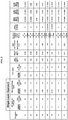
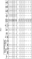
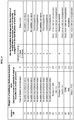
- FIG. 2 provides exemplary polymer binder matrix compositions where the water dispersible conductive polymeric material is present within the aqueous coatable dye-receiving layer for single-layer DRL aspects-i.e., none of the samples in FIG. 2 had an ROC layer and therefore is within the claims.
- C1-C6 represent control samples.
- control examples C1-C4 conductive polymeric material was added to sub-layers and not to the DRL. While all four samples exhibited no buckling and no creasing, all but C1 suffered from image bleeding. Image bleeding was measured after one week at variable conditions: 35°C/50% relative humidity; 40°C/50% relative humidity; and 50°C/50% relative humidity. Control sample C1 did not suffer from either buckling/creasing or image bleeding. However, to achieve such results, it was required to increase the thickness of the DRL significantly. Control examples C5 and C6 did not include any conductive polymeric material in the DRL and both test samples resulted in undesirable buckling and creasing.
- conductive polymeric material was added to the DRL, as opposed to the sub-layers. Both E1 and E2 exhibited no buckling, no creasing, and no image bleeding. Yet, the DRL thickness was held at 1.4 ⁇ m and a significantly less amount of conductive material was required. Therefore, by adding conductive polymeric material to the DRL, the inventors were able to avoid undesirable buckling, creasing, and image bleeding without having to sacrifice the thinness of the DRL and without having to add a significant amount of conductive material.
- the surface electrical resistance (“SER") of each sample was also tested. During printing, it is advantageous to maintain low surface resistivity to dissipate static electricity. As can be seen in FIG. 2 , adding conductive polymeric material to the DRL helps with achieving this desired result.
- FIG. 3 provides exemplary polymer binder matrix compositions where the water dispersible conductive polymeric material has been added to the receiver overcoat layer, which is placed over the aqueous coatable dye-receiving layer (for two-layer ROC/DRL embodiments).
- C8-C13 represent control samples
- E3-E9 represent examples according to the invention.
- the samples detailed in FIG. 3 were observed for surface electrical resistance, buckling/creasing effects, and effects on image quality.
- conductive polymeric material was added to the ROC. As can be seen in samples C8-C13 in FIG.
- the polymer binder matrix forms the predominant structure of both the dye-receiving layer and the receiver overcoat layer and contains essentially no other polymers but (1) the water-dispersible acrylic polymer and (2) the water-dispersible polyester. and (3) the water-dispersible conductive polymeric material described above.
- lesser amounts typically, less than 10 weight % of the total dry weight of the respective layer
- additional components may include conductive polymeric material (described previously), as well as crosslinking agents, release agents, additional surfactant, and dispersants (discussed more fully below).
- the aqueous coatable dye-receiving layer and/or the receiver overcoat layer comprises one or more water-dispersible release agents that can reduce sticking that occurs between a thermal donor element and the thermal image receiver element of this invention during thermal imaging.
- These compounds are generally not water-soluble, but are water dispersible so that they are dispersed uniformly within the aqueous image receiving layer formulation (described above). Release agents can also help provide a uniform film in the dry image receiving layer during formulation and drying.
- These compounds can be polymeric or non-polymeric, but are generally polymeric. Such compounds are not generally re-dispersible once they are coated and dried in the aqueous coatable dye-receiving layer.
- Useful water-dispersible release agents include but are not limited to, water-dispersible fluorine-based surfactants, silicone-based surfactants, modified silicone oil (such as epoxy-modified, carboxy-modified, amino-modified, alcohol-modified, fluorine-modified, alkylarylalkyl-modified, and others known in the art), and polysiloxanes.
- Useful modified polysiloxanes include but are not limited to, water-dispersible polyoxyalkylene-modified dimethylsiloxane graft copolymers having at least one alkylene oxide pendant chain having more than 45 alkoxide units, as described in U.S. Patent 5,356,859 (Lum et al. ).
- Other useful release agents include crosslinked amino modified polydimethylsiloxanes that can be supplied as emulsions under the tradename Siltech® from Siltech Corporation. Some useful commercial products of this type are described below in the Examples.
- the useful amounts of one or more water-dispersible release agents in the dry image receiving layer are generally at least 0.5 weight % and up to and including 10 weight %, or typically at least 1 weight % and up to and including 5 weight %, based on the total weight of the dry image receiving layer.
- the amount of water-dispersible release agent refers to the amount of the compound, not the amount of a formulation or emulsion in which the compound may be supplied.
- the aqueous coatable dye-receiving layer and receiver overcoat layer can also include residual crosslinking agents. Most of the crosslinking agents used in the image receiving layer formulation are reacted during the preparation of the thermal image receiver element, but some may be residual in the aqueous coatable dye-receiving layer. Useful crosslinking agents are described below.
- Useful crosslinking agents that can be included in the aqueous image receiving layer formulation and or the aqueous coatable receiver overcoat layer are chosen to be reactive with the particular reactive groups on the water-dispersible acrylic polymers incorporated into the polymer binder matrix.
- the useful crosslinking agents are carbodiimides and aziridines.
- One or more crosslinking agents can be present in either or both of the aqueous image receiving layer formulation or aqueous receiver overcoat layer formulation in an amount that is essentially a 1:1 molar ratio or less with the reactive groups in the water-dispersible acrylic polymer in the formulation.
- useful crosslinking agents include but are not limited to, organic compounds such as melamine formaldehyde resins, glycoluril formaldehyde resins, polycarboxylic acids and anhydrides, polyamines, epihalohydrins, diepoxides, dialdehydes, diols, carboxylic acid halides, ketenes, aziridines, carbodiimides, isocyanates, and mixtures thereof.
- the aqueous coatable ROC and aqueous coatable DRL each may contain one more of any of the following additional addenda: plasticizers, defoamers, coating aids, charge control agents, thickeners or viscosity modifiers, antiblocking agents, UV absorbers, coalescing aids, matte beads (such as organic matte particles), antioxidants, stabilizers, and fillers as is known in the art for aqueous-coated formulations
- plasticizers defoamers
- coating aids charge control agents
- thickeners or viscosity modifiers antiblocking agents
- UV absorbers coalescing aids
- matte beads such as organic matte particles
- antioxidants stabilizers
- fillers as is known in the art for aqueous-coated formulations
- the receiver overcoat layer comprises a polymer binder matrix consisting essentially of (1) a water-dispersible acrylic polymer and (2) a water-dispersible polyester, as well as (3) a water-dispersible conductive polymeric material.
- the ROC layer may further comprise one or more release agents, one or more crosslinking agents, one or more antifoamers, and one or more surfactants or emulsifiers.
- an amount of surfactant is added to the aqueous ROC dispersion. Namely, surfactant is added to the ROC dispersion after the acrylic polymer is already formed, which is in addition to the amount of surfactant that is used as an emulsifier in the manufacture or suspension of the acrylic polymer. Hence, such added surfactant is sometimes referred to herein as "additional surfactant.”
- a surfactant/emulsifier is required to manufacture acrylic polymers with water dispersible properties.
- "excess surfactant” is added at the time that the acrylic polymer is made.
- This excess surfactant is an extra amount of surfactant in excess of what is required to actually make the acrylic polymer and is added at the time that the acrylic polymer is actually made.
- surfactant in the amount of 1% is required for the manufacture of acrylic polymers.
- “excess surfactant” is the amount of surfactant used to make the acrylic polymers that is in excess of 1%. For example, FIG.
- Group (c) monomers are styrene or styrene derivatives
- Group (a) monomers are ethylenically unsaturated polymerizable acrylates or methacrylates comprising acyclic alkyl, cycloalkyl, or aryl ester groups having at least 4 carbon atoms
- Group (b) monomers are carboxy-containing or sulfo-containing ethylenically unsaturated polymerizable acrylate or methacrylate.
- Useful surfactants are anionic or non-ionic surfactants.
- Useful anionic surfactants include, but are not limited to, the following: Rhodocal® A-246 (Sodium C14-C16 sulfonate), Rhodapex® CO-436 (40% solids in 12-16% ethanol); DOWFAX 2A1 (alkyldiphenyloxide disulfonate), SDBS (Sodium Dodecyl Benzenesulfonate) and ADS (sodium dodecyl sulfate).
- Useful non-ionic surfactants include, but are not limited to, the following: Olin-10GTM (P-isonoylphenoxypoly(glycidol)) or SILWET L-7230 (a copolymer of silicone, ethylenoxide and propyleneoxide).
- the amount of "excess” or “additional” surfactant added to the formulation is in the range from 1% to 5% by weight, or 2% to 5% by weight, or by 3% to 4% by weight. In certain embodiments the additional surfactant is added to the formulation at about 2.5% by weight, or 1 % to 3 % by weight, or 2% to 2.5% by weight, or 2% to 3% by weight.
- the inventors were able to reduce the number of misregistrations. Because misregistrations appear to happen more frequently at the end of the donor ribbon spool, the inventors judged visual registration and registration accuracy by testing and analyzing the last section of prints of a donor spool (for example, the last 50 pages when the donor spool normally would print about 250 prints). As one skilled in the art would appreciate, when there is a misregistration, the print quality is reduced as the lines, edges, or boundaries are fuzzy and not sharp. Moreover, misregistrations cause the edges or boundaries to be incorrectly colored because of incorrect overlap of the various colors of the donor element that are transferred to the receiver element.
- the blue and yellow dye are transferred to the receiver element on top of each other.
- the edges or boundaries of the print may appear either yellow or blue, instead of green, because there was not a perfect overlap of the blue and yellow dye to achieve the green color.
- foams are easily generated during the preparation of dispersions and during any subsequent coating application process. Foaming occurs particularly when dispersions, like the ones discussed previously, undergo high shearing processes. High shearing processes include high-speed stirring at about 1000 rpm (revolution per minute) or greater and high-speed coating application at about 150 mpm (meter per minute) or greater. During a high shearing process, an objectionable amount of foam is generated, which usually causes coating defects, unwanted compositional fluctuation, and messy overflow, among other undesirable effects. Moreover, excess foaming requires one to frequently change the filters of the coating equipment.
- antifoamers include compounds with high silicone content, such as structured siloxane defoamers, polyorganosiloxane, resinous siloxane compounds, and polyether siloxane copolymers.
- Useful antifoamers include, but are not limited to, the commercially available antifoamers listed in FIG. 7 .
- FIG. 7 is a table showing how various concentrations of various types of antifoamers affect the foam height above initial liquid level after the aqueous dispersion has been subjected to a high shearing process.
- the sample dispersions each underwent high-speed mixing at 2000 rpm for two minutes. Foam height measurements were taken immediately after the mixing process ended ("0 minutes after 2 min mix"), one minute after the mixing process ended, and two minutes after the mixing process ended.
- control dispersion sample C1 did not include an antifoamer, and as expected, the foam height above initial liquid level was at one of the highest levels observed of any sample.
- Dispersion samples F1-F17 each included an antifoamer at varying amounts, but none of those dispersion samples effectively reduced foam levels after a high shearing stirring process.
- Dispersion samples E10-E30 proved more effective at reducing foam levels after a high shearing stirring process. The results in FIG. 7 evidence that certain types of antifoamers effectively reduce foam levels after high shearing processes, whereas other types of antifoamers do not effectively reduce foam levels.
- each of the DRL dispersion samples listed in FIG. 7 comprise all of the same components-namely, a water-dispersible acrylic polymer, a water-dispersible polyester, a release agent, a cross-linking agent, and a surfactant.
- FIG. 6 is a table showing how various concentrations of various types of antifoamers affect the foam height above the initial liquid level of several aqueous DRL dispersions.
- All of the dispersion samples E1-E12 and C13-C14 are aqueous DRL dispersions comprising the same cross-linking agent, release agent, water-dispersible polyester, and water-dispersible acrylic polymer.
- the weight ratio of water-dispersible acrylic polymer to water-dispersible polyester present was roughly 9:1, and the water-dispersible acrylic polymer consisted of about 3% by weight of Group (b) monomers-carboxy-containing or sulfo-containing ethylenically unsaturated polymerizable acrylate or methacrylate.
- the two control dispersion samples (C13 and C14) did not include an antifoamer.
- the foam height for the two control samples was much higher than the foam height for the exemplary samples (E1-E12), which all included some type of antifoamer.
- Samples E7-E12 each displayed very desirable results, as the foam was reduced entirely just two minutes after mixing. As shown in FIGS.
- antifoamers to the DRL in an amount equal to or greater than 0.04 weight %, or in a range of 0.04 to 0.32 weight %, or in an amount ranging from 0.16 to 0.32 weight %.
- the several aqueous DRL dispersion embodiments of FIG. 6 also comprise at least one surfactant and/or dispersant (except for control example C13, which does not comprise any surfactant or dispersant).
- Dispersing agents also known as dispersants, are typically fairly low-molecular weight materials that strongly adsorb on to pigment particles. Generally, dispersants may consist of one or more surfactants. To provide optimal performance, pigment particles must act independently of each other and thus must remain well dispersed throughout manufacture, storage, application, and film formation. To achieve these advantageous properties, certain embodiments of the present invention have a DRL that comprises one or more surfactants in combination with one or more dispersants.
- the one or more surfactants may be present in an amount up to approximately 10 weight % based on the total dry weight of the DRL, or more specifically 1 to 6 weight %.
- the one or more dispersants may be present in an amount up to approximately 10 weight % based on the total dry weight of the DRL, or more specifically from 1 to 3 weight %.
- FIG. 6 illustrates certain aqueous DRL embodiments that comprise Olin-10GTM in combination with one or more dispersants.
- Useful dispersants include BmE-77, which is described below with reference to FIGS. 8A-8B , and FS-30, which is commercially available from multiple raw material suppliers (e.g., Castament® FS-30 by BASF and Capstone® FS-30 by DUPONT).
- dispersants or surfactants are employed in the ROC and DRL to enhance the dispersion stability and to improve filterability.
- Unwanted dispersed particle build-up and coagulation of ROC and DRL dispersions may be observable in a coating machine during or after high-speed, high-sheer coating processes.
- the presence of build-up in the form of deposits and agglomerates requires frequent cleaning of coating machinery and filter changes during the coating application process. Failure to monitor such build-up and maintain clean machinery can affect the coating quality as a result.
- the inventors discovered that by incorporating suitable type and amount of dispersants can significantly enhance the dispersion stability with improved filterability. Filterability testing was conducted and the results are detailed in FIGS. 8A-8B .
- FIG. 8A shows the filterability of various ROC dispersions based on the filtrate quality testing (“FQT”) method, which is quantified by the weight to plug (“WTP”) metric.
- FQT filtrate quality testing
- WTP weight to plug
- each dispersion sample is detailed by the data listed in columns numbered 1 to 10.
- the contents were added in order according to column numbering-i.e., the component in column 1 was added first, then the component in column two was added, and so on.
- Columns 2 and 3 represent surfactants or dispersants that were added to the dispersion samples.
- Olin-10GTM is a surfactant
- BmE-77 is a dispersant.
- BmE-77 is an acronym that represents the components of the dispersant: "Bm” represents benzyl methacrylate, “E” represents methacrylic acid, and “77” represents the weight percent of benzyl methacrylate in the latex polymer. Thus, BmE-77 consists of 77% by weight of benzyl methacrylate and the balance methacrylic acid. Dispersant can be included in the ROC in an amount ranging from 1% up to and including 10% by weight, or more specifically, 2% to 8%, or 1% to 3% by weight, based on the total dry weight of the ROC layer. In column 4, “XL-1" represents that a cross-linking agent was added to the dispersion.
- the "L-2%E” represents that the acrylic latex (“L") is comprised of 2% of (b)-type carboxy-containing or sulfo-containing ethylenically unsaturated polymerizable acrylate or methacrylate monomers that were discussed previously.
- "L-3%E” represents that (b) carboxy-containing or sulfo-containing ethylenically unsaturated polymerizable acrylate or methacrylate monomers make up 3% of the acrylic latex.
- Columns 9 and 10 represent different solvents that were added to the dispersion samples.
- "IBA” represents the solvent isobutyl alcohol
- “DEG” represents diethylene glycol.
- FIG. 8B shows the filterability of various DRL dispersions based on the filtrate quality testing ("FQT") method. Except for the components that are specifically stated in FIG. 8B , the dispersion samples listed all comprise the same components. In other words, all of the dispersion samples in FIG. 8B (E11, E12, C13, and C14) comprise the same cross-linking agent, release agent, water-dispersible polyester, and water-dispersible acrylic polymer In fact, the dispersions of FIG. 8B correspond directly by dispersion ID number to the dispersions of FIG. 6 . As illustrated in FIG.
- the incorporation of surfactants and dispersants (such as Olin-10GTM, BmE-77, and/or FS-30) in the DRL dispersion helps improve the filterability of the dispersion by more than 40% when compared to control example C13, which did not include any surfactant or dispersant in its formulation.
- Olin-10GTM and BmE-77 used in E11 and E12 provides an additional coating quality advantage over control examples C13 and C14, which both lack the dispersant BmE-77.
- DRL build-up was observable on coating equipment after just a short time into the coating process for control dispersions C13 and C14-both lacking dispersant-whereas build-up was not observable during coating of DRL dispersions E11 and E12-both inclusive of a dispersant.
- Build-up on the coating equipment, particularly the coating rollers is undesirable because it causes persistent coating impressions and objectionable coating defects on the supports that are obvious to the naked eye.
- Dye receiver elements used in thermal dye transfer generally include a support (transparent or reflective) bearing on one or both sides thereof a dye image-receiving layer, and optionally additional layers, such as a compliant or cushioning layer between the support and the dye-receiving layer.
- FIGS. 1A and 1B show that the aqueous DRL layer lies on top of the microvoided compliant layer.
- the dye-receiving layer may be coated directly on one or both opposing sides of a support.
- the aqueous DRL may be coated on top of an additional layer (such as a compliant layer), which resides on one or both opposing sides of the support.
- the compliant layer provides insulation to keep heat generated by the thermal head at the surface of the print, and also provides close contact between the donor ribbon and receiving sheet, which is essential for uniform print quality.
- Various approaches have been suggested for providing such a compliant layer.
- U.S. Patent No. 5,244,861 Campbell et al.
- U.S. Patent No. 6,372,689 describes the use of a hollow particle layer between the support and dye-receiving layer
- U.S. Patent No. 8,435,925 Dontula et al.
- FIGS. 1A and 1B illustrate that a similar microvoided compliant layer is included between the outermost layer and the support.
- the microvoided compliant layer may comprise one or more layers, such as skin layers and film layers.
- the microvoided compliant layer shown in FIGS. 1A and 1B should be understood to be any type of compliant layer known in the art.
- the thermal image receiver elements comprise one or more layers as described above, disposed over a suitable support. As noted above, these layers can be disposed on one or both sides of the support. From the outermost surface to the support, the thermal image receiver elements comprise an aqueous coatable dye-receiving layer and optionally one or more intermediate layers. However, in many embodiments, the aqueous coatable dye-receiving layer is disposed directly on one or both sides of the support.
- a particularly useful support comprises a polymeric film or a raw paper base comprising cellulose fibers, or a synthetic paper base comprising synthetic polymer fibers, or a resin coated cellulosic paper base. But other base supports such as fabrics and polymeric films can be used.
- the support can be composed of any material that is typically used in thermal imaging applications as long as the layer formulations described herein can be suitably applied thereof.
- the resins used on either or both sides of a paper base are thermoplastics like polyolefins such as polyethylene, polypropylene, copolymers of these resins, or blends of these resins, in a suitable dry thickness that can be adjusted to provide desired curl characteristics.
- the surface roughness of this resin layer can be adjusted to provide desired conveyance properties in thermal imaging printers.
- the support can be transparent or opaque, reflective or non-reflective.
- Opaque supports include plain paper, coated paper, resin-coated paper such as polyolefin-coated paper, synthetic paper, low density foam core based support, and low density foam core based paper, photographic paper support, melt-extrusion-coated paper, and polyolefin-laminated paper.
- the papers include a broad range of papers, from high end papers, such as photographic paper to low end papers, such as newsprint.
- Ektacolor® paper Eastman Kodak Co.
- the paper can be made on a standard continuous fourdrinier wire machine or on other modern paper formers. Any pulp known in the art to provide paper can be used. Bleached hardwood chemical kraft pulp is useful as it provides brightness, a smooth starting surface, and good formation while maintaining strength.
- Papers useful in this invention are generally of caliper of at least 50 ⁇ m and up to and including 230 ⁇ m and typically at least 100 ⁇ m and up to and including 190 ⁇ m, because then the overall imaged element thickness is in the range desired by customers and for processing in existing equipment. They can be "smooth" so as to not interfere with the viewing of images. Chemical additives to impart hydrophobicity (sizing), wet strength, and dry strength can be used as needed. Inorganic filler materials such as TiO 2 , talc, mica, BaSO 4 and CaCO 3 clays can be used to enhance optical properties and reduce cost as needed. Dyes, biocides, and processing chemicals can also be used as needed. The paper can also be subject to smoothing operations such as dry or wet calendering, as well as to coating through an in-line or an off-line paper coater.
- a particularly useful support is a paper base that is coated with a resin on either side.
- Biaxially oriented base supports include a paper base and a biaxially oriented polyolefin sheet, typically polypropylene, laminated to one or both sides of the paper base.
- Such supports can contain pigments, air voids or foam voids to enhance their opacity.
- the support can also comprise microporous materials such as polyethylene polymer-containing material sold by PPG Industries, Inc., Pittsburgh, Pennsylvania under the trade name of Teslin®, Tyvek® synthetic paper (DuPont Corp.), impregnated paper such as Duraform®, and OPPalyte® films (Mobil Chemical Co.) and other composite films listed in U.S. Patent 5,244,861 .
- Useful composite sheets are disclosed in, for example, U.S. Patents 4,377,616 (Ashcraft et al. ), 4,758,462 (Park et al. ), and 4,632,869 (Park et al. ).
- the support can be voided, which means voids formed from added solid and liquid matter, or "voids" containing gas.
- the void-initiating particles, which remain in the finished packaging sheet core, should be from at least 0.1 and up to and including 10 ⁇ m in diameter and typically round in shape to produce voids of the desired shape and size.
- Microvoided polymeric films are particularly useful in some embodiments. For example, some commercial products having these characteristics that can be used as support are commercially available as 350K18 from ExxonMobil and KTS-107 (from HSI, South Korea).
- Biaxially oriented sheets while described as having at least one layer, can also be provided with additional layers that can serve to change the properties of the biaxially oriented sheet. Such layers might contain tints, antistatic or conductive materials, or slip agents to produce sheets of unique properties.
- Biaxially oriented sheets can be formed with surface layers, referred to herein as skin layers, which would provide an improved adhesion, or look to the support and photographic element.
- the biaxially oriented extrusion can be carried out with as many as 10 layers if desired to achieve some particular desired property.
- the biaxially oriented sheet can be made with layers of the same polymeric material, or it can be made with layers of different polymeric composition.
- Useful transparent supports can be composed of glass, cellulose derivatives, such as a cellulose ester, cellulose triacetate, cellulose diacetate, cellulose acetate propionate, cellulose acetate butyrate, polyesters, such as poly(ethylene terephthalate), poly(ethylene naphthalate), poly-1,4-cyclohexanedimethylene terephthalate, poly(butylene terephthalate), and copolymers thereof, polyimides, polyamides, polycarbonates, polystyrene, polyolefins, such as polyethylene or polypropylene, polysulfones, polyacrylates, polyether imides, and mixtures thereof.
- transparent means the ability to pass visible radiation without significant deviation or absorption.
- the support used in the thermal image receiver elements can have a thickness of at least 50 ⁇ m and up to and including 500 ⁇ m or typically at least 75 ⁇ m and up to and including 350 ⁇ m.
- Antioxidants, brightening agents, antistatic or conductive agents, plasticizers and other known additives can be incorporated into the support, if desired.
- Useful antistatic agents in the substrate include but are not limited to, metal particles, metal oxides, inorganic oxides, metal antimonates, inorganic non-oxides, and electronically conductive polymers, examples of which are described in U.S. Patent Application 2011/0091667 (noted above).
- Particularly useful antistatic agents are inorganic or organic electrolytes. Alkali metal and alkaline earth salts (or electrolytes) such as sodium chloride, potassium chloride, and calcium chloride, and electrolytes comprising polyacids are useful.
- alkali metal salts include lithium, sodium, or potassium polyacids such as salts of polyacrylic acid, poly(methacrylic acid), maleic acid, itaconic acid, crotonic acid, poly(sulfonic acid), or mixed polymers of these compounds.
- the raw base support can contain various clays such as smectite clays that include exchangeable ions that impart conductivity to the raw base support.
- Polymerized alkylene oxides such as combinations of polymerized alkylene oxide and alkali metal salts as described in U.S. Patents 4,542,095 (Steklenski et al. ) and 5,683,862 (Majumdar et al. ) are useful as electrolytes.
- the antistatic agents can be present in the support (such as a cellulose raw base support) in an amount of up to 0.5 weight % or typically at least 0.01 weight % and up to and including 0.4 weight % based on the total support dry weight.
- the base support comprises a synthetic paper that is typically cellulose-free, having a polymer core that has adhered thereto at least one flange layer.
- the polymer core comprises a homopolymer such as a polyolefin, polystyrene, polyester, polyvinylchloride, or other typical thermoplastic polymers; their copolymers or their blends thereof; or other polymeric systems like polyurethanes and polyisocyanurates. These materials can have been expanded either through stretching resulting in voids or through the use of a blowing agent to consist of two phases, a solid polymer matrix, and a gaseous phase. Other solid materials can be present in the form of fillers that are of organic (polymeric, fibrous) or inorganic (glass, ceramic, metal) origin.
- the support comprises a synthetic paper that can be cellulose-free, having a foamed polymer core or a foamed polymer core that has adhered thereto at least one flange layer.
- the polymers described for use in a polymer core can also be employed in manufacture of the foamed polymer core layer, carried out through several mechanical, chemical, or physical means as are known in the art.
- polyolefins such as polyethylene and polypropylene, their blends and their copolymers are used as the matrix polymer in the foamed polymer core along with a chemical blowing agent such as sodium bicarbonate and its mixture with citric acid, organic acid salts, azodicarbon-amide, azobisformamide, azobisisobutyrolnitrile, diazoaminobenzene, 4,4'-oxybis(benzene sulfonyl hydrazide) (OBSH), N,N'-dinitrosopentamethyl-tetramine (DNPA), sodium borohydride, and other blowing agent agents well known in the art.
- a chemical blowing agent such as sodium bicarbonate and its mixture with citric acid, organic acid salts, azodicarbon-amide, azobisformamide, azobisisobutyrolnitrile, diazoaminobenzene, 4,4'-oxybis(benzene sulfonyl hydrazide) (
- Useful chemical blowing agents would be sodium bicarbonate/citric acid mixtures, azodicarbonamide; though others can also be used. These foaming agents can be used together with an auxiliary foaming agent, nucleating agent, and a cross-linking agent.
- the thermal image receiver element comprises an aqueous coatable dye-receiving layer on only one side of the support
- a slip layer or anti-curl layer on the "backside" (non-imaging) of the support using suitable polymers such as acrylate or methacrylate polymers, vinyl resins such as copolymers derived from vinyl chloride and vinyl acetate, poly(vinyl alcohol-co-vinyl butyral), polyvinyl acetate, cellulose acetate, or ethyl cellulose.
- the backside slip layer can also comprise one or more suitable antistatic agents or anti-conductive agents that arc known in the art.
- This slip layer can also include lubricants such as oils or semicrystalline organic solids such as beeswax. poly(vinyl stearyl), perfluorinated alkyl ester polyethers, polycaprolactone, silicone oils, or any combination thereof, as described for example in U.S. Patent 5,866,506 (Tutt et al. ).
- Useful anti-curl layers can comprise one or more polyolefins such mixtures of polyethylene and polypropylene.
- thermal image receiver elements of this invention can be prepared as follows.
- An image receiving layer was prepared by applying an aqueous coatable dye-receiving image receiving layer formulation to at least one side of a support, and in some embodiments, the same or different aqueous coatable dye-receiving layer formulations can be applied to opposing sides of a support to provide a duplex thermal image receiving element.
- the applied aqueous coatable dye-receiving layer formulation comprises a polymer binder composition that consists essentially of the (1) and (2) polymer components described above and any optional addenda such as a surfactant used as an emulsifier for making the water-dispersible acrylic polymer, one or more release agents, one or more crosslinking agents and any other addenda described herein.
- the weight ratio of the water-dispersible acrylic polymer to the water-dispersible polyester in such formulations is at least 1:1 to and including 6:1, or typically at least 1.5:1 to and including 5:1.
- the weight ratio of the water-dispersible acrylic polymer to the water-dispersible polyester in such formulations is at least 1:1 to and including 9.2:1.
- the one or more water-dispersible acrylic polymers are present in the polymer binder matrix at a dry ratio to the water-dispersible polyester of at least 1:1, or typically at least 4:1 and up to and including 20:1, or more likely at least 1:1 and up to and including 20:1, or even at least 4:1 and up to and including 15:1.
- These formulations can be applied to the support using any useful technique including coating with appropriate equipment and conditions, including but not limited to hopper coating, curtain coating, rod coating, gravure coating, roller coating, dip coating, and spray coating.
- the support materials are described above, but before applying the aqueous coatable dye-receiving layer formulation, the support can be treated to improve adhesion using any suitable technique such as acid etching, flame treatment, corona discharge treatment, or glow discharge treatment, or it can be treated with a suitable primer layer.
- any suitable technique such as acid etching, flame treatment, corona discharge treatment, or glow discharge treatment, or it can be treated with a suitable primer layer.
- a conductive image receiving layer was prepared by applying an aqueous coatable dye-receiving image receiving layer formulation comprising a conductive polymer to at least one side of a support, and in some embodiments, the same or different aqueous coatable dye-receiving layer formulations can be applied to opposing sides of a support to provide a duplex thermal image receiving element.
- the applied aqueous coatable dye-receiving layer formulation comprises a polymer binder composition that consists essentially of the (1) water-dispersible acrylic polymer, (2) water-dispersible polyester, and (3) water-dispersible conductive polymeric material components described above and any optional addenda such as one or more surfactants or dispersants used as an emulsifier for the water-dispersible acrylic polymer, one or more release agents, one or more crosslinking agents, and any other addenda described above.
- the weight ratio of the water-dispersible acrylic polymer to the water-dispersible polyester in such formulations is at least 1:1 to and including 6:1, or typically at least 1.5:1 to and including 5:1.
- the weight ratio of the water-dispersible acrylic polymer to the water-dispersible polyester in such formulations is at least 1:1 to and including 9.2:1.
- the one or more water-dispersible acrylic polymers are present in the polymer binder matrix at a dry ratio to the water-dispersible polyester of at least 1:1, or typically at least 4:1 and up to and including 20:1, or more likely at least 1:1 and up to and including 20:1, or even at least 4:1 and up to and including 15:1.
- the amount of the (3) water dispersible conductive polymeric material in the formulation ranges from > 0.75% to 2% or 1.0% to 1.25%.
- formulations can be applied to the support using any useful technique including coating with appropriate equipment and conditions, including but not limited to hopper coating, curtain coating, rod coating, gravure coating, roller coating, dip coating, and spray coating.
- the support materials are described above, but before applying the aqueous coatable dye-receiving layer formulation, the support can be treated to improve adhesion using any suitable technique such as acid etching, flame treatment, corona discharge treatment, or glow discharge treatment, or it can be treated with a suitable primer layer.
- the image receiving layer is composed of two layers, namely, an aqueous coatable dye-receiving layer and an aqueous coatable overcoat layer comprising a conductive polymer.
- the image layer was prepared by first applying an aqueous coatable dye-receiving image receiving layer formulation to at least one side of a support, and in some embodiments, the same or different aqueous coatable dye-receiving layer formulations can be applied to opposing sides of a support to provide a duplex thermal image receiving element.
- the applied aqueous coatable dye-receiving layer formulation comprises a polymer binder composition that consists essentially of the (1) water-dispersible acrylic polymer and (2) water-dispersible polyester components described above and any optional addenda such as one or more surfactants or dispersants used as an emulsifier for making the water-dispersible acrylic polymer, one or more release agents, one or more crosslinking agents, and any other addenda described herein.
- the weight ratio of the water-dispersible acrylic polymer to the water-dispersible polyester in such formulations is at least 1:1 to and including 6:1, or typically at least 1.5:1 to and including 5:1.
- the weight ratio of the water-dispersible acrylic polymer to the water-dispersible polyester in such formulations is at least 1:1 to and including 9.2:1.
- the one or more water-dispersible acrylic polymers are present in the polymer binder matrix at a dry ratio to the water-dispersible polyester of at least 1:1, or typically at least 4:1 and up to and including 20:1, or more likely at least 1:1 and up to and including 20:1, or even at least 4:1 and up to and including 15:1.
- formulations can be applied to the support using any useful technique including coating with appropriate equipment and conditions, including but not limited to hopper coating, curtain coating, rod coating, gravure coating, roller coating, dip coating, and spray coating.
- the support materials are described herein, but before applying the aqueous coatable dye-receiving layer formulation, the support can be treated to improve adhesion using any suitable technique such as acid etching, flame treatment, corona discharge treatment, or glow discharge treatment, or it can be treated with a suitable primer layer.
- an overcoat layer was prepared by applying an aqueous coatable dye-receiving image receiving layer formulation comprising a conductive polymer overcoated to the dye-receiving layer at least on one side of a support coated with an aqueous coatable dye-receiving layer, and in some embodiments, the same or different aqueous coatable dye-receiving layer formulations comprising a conductive polymer can be applied to opposing sides of a support coated with an aqueous coatable dye-receiving layer to provide a duplex thermal image receiving element.
- the applied aqueous coatable overcoat layer formulation comprises a polymer binder composition that consists essentially of the (1) water-dispersible acrylic polymer, (2) water-dispersible polyester, and (3) water-dispersible conductive polymeric material components described above and any optional addenda such as one or more surfactants or dispersants used as an emulsifier for making the water-dispersible acrylic polymer (described herein), one or more release agents, one or more crosslinking agents (described herein), and any other addenda described herein.
- the weight ratio of the water-dispersible acrylic polymer to the water-dispersible polyester in such formulations is at least 1:1 to and including 6:1, or typically at least 1.5:1 to and including 5:1.
- the weight ratio of the water-dispersible acrylic polymer to the water-dispersible polyester in such formulations is at least 1:1 to and including 9.2:1.
- the one or more water-dispersible acrylic polymers are present in the polymer binder matrix at a dry ratio to the water-dispersible polyester of at least 1:1, or typically at least 4:1 and up to and including 20:1, or more likely at least 1:1 and up to and including 20:1, or even at least 4:1 and up to and including 15:1.
- the amount of water dispersible conductive polymeric material in the formulation ranges from > 1.2% to 3%, >1% to 3% by weight, >1% by weight, >1.4% by weight.
- formulations can be applied to the support using any useful technique including coating with appropriate equipment and conditions, including but not limited to hopper coating, curtain coating, rod coating, gravure coating, roller coating, dip coating, and spray coating.
- the support materials are described above, but before applying the aqueous coatable dye-receiving layer formulation, the support can be treated to improve adhesion using any suitable technique such as acid etching, flame treatment, corona discharge treatment, or glow discharge treatment, or it can be treated with a suitable primer layer.
- the image receiving layer is composed of two layers, namely, an aqueous coatable dye-receiving layer and an aqueous coatable overcoat layer comprising additional surfactant and conductive polymer.
- the image layer was prepared by first applying an aqueous coatable dye-receiving image receiving layer formulation to at least one side of a support, and in some embodiments, the same or different aqueous coatable dye-receiving layer formulations can be applied to opposing sides of a support to provide a duplex thermal image receiving element.
- the applied aqueous coatable dye-receiving layer formulation comprises a polymer binder composition that consists essentially of the (1) water-dispersible acrylic polymer and (2) water-dispersible polyester components described above and any optional addenda such as a surfactant used as an emulsifier used for making the water-dispersible acrylic polymer, one or more release agents, one or more crosslinking agents, and any other addenda described herein.
- the weight ratio of the water-dispersible acrylic polymer to the water-dispersible polyester in such formulations is at least 1:1 to and including 6:1, or typically at least 1.5:1 to and including 5:1.
- the weight ratio of the water-dispersible acrylic polymer to the water-dispersible polyester in such formulations is at least 1:1 to and including 9.2:1.
- the one or more water-dispersible acrylic polymers are present in the polymer binder matrix at a dry ratio to the water-dispersible polyester of at least 1:1, or typically at least 4:1 and up to and including 20:1, or more likely at least 1:1 and up to and including 20:1, or even at least 4:1 and up to and including 15:1.
- formulations can be applied to the support using any useful technique including coating with appropriate equipment and conditions, including but not limited to hopper coating, curtain coating, rod coating, gravure coating, roller coating, dip coating, and spray coating.
- the support materials are described above, but before applying the aqueous coatable dye-receiving layer formulation, the support can be treated to improve adhesion using any suitable technique such as acid etching, flame treatment, corona discharge treatment, or glow discharge treatment, or it can be treated with a suitable primer layer.
- an overcoat layer was prepared by applying an aqueous coatable dye-receiving image receiving layer formulation comprising an additional surfactant and conductive polymer to the aqueous coatable dye-receiving layer described herein (or as described in (A)) at least on one side of a support coated with an aqueous coatable dye-receiving layer, and in some embodiments, the same or different aqueous coatable dye-receiving layer formulations comprising additional surfactant and a conductive polymer can be applied to opposing sides of a support coated with an aqueous coatable dye-receiving layer to provide a duplex thermal image receiving element.
- the applied aqueous coatable overcoat layer formulation comprises a polymer binder composition that consists essentially of the (1) water-dispersible acrylic polymer, (2) water-dispersible polyester, and (3) water-dispersible conductive polymeric material components described herein and additional surfactants, and optional addenda such as a surfactant used in the emulsification of the water-dispersible acrylic polymer, one or more release agents, one or more crosslinking agents, and any other addenda described herein.
- the weight ratio of the water-dispersible acrylic polymer to the water-dispersible polyester in such formulations is at least 1:1 to and including 6:1, or typically at least 1.5:1 to and including 5:1.
- the weight ratio of the water-dispersible acrylic polymer to the water-dispersible polyester in such formulations is at least 1:1 to and including 9.2:1.
- the one or more water-dispersible acrylic polymers are present in the polymer binder matrix at a dry ratio to the water-dispersible polyester of at least 1:1, or typically at least 4:1 and up to and including 20:1, or more likely at least 1:1 and up to and including 20:1, or even at least 4:1 and up to and including 15:1.
- the amount of water dispersible conductive polymeric material is as discussed above.
- the amount of additional surfactant added to the formulation is as discussed above.
- formulations can be applied to the support using any useful technique including coating with appropriate equipment and conditions, including but not limited to hopper coating, curtain coating, rod coating, gravure coating, roller coating, dip coating, and spray coating.
- the support materials are described above, but before applying the aqueous coatable dye-receiving layer formulation, the support can be treated to improve adhesion using any suitable technique such as acid etching, flame treatment, corona discharge treatment, or glow discharge treatment, or it can be treated with a suitable primer layer.
- the formulation After the formulation is applied as described in (A) to (D) above, it is dried under suitable conditions of at least 20°C and up to and including 100°C, and typically at a temperature of at least 60°C. Drying can be carried out in an oven or drying chamber if desired, especially in a manufacturing apparatus or production line. Drying facilitates in the crosslinking of the aqueous image receiving layer formulation and especially through the reactive groups in the water-dispersible acrylic polymer using the appropriate crosslinking agent. Crosslinking can improve the adhesion of the aqueous coatable dye-receiving layer to the support or any immediate layer that is disposed below the aqueous coatable dye-receiving layer.
- the aqueous coatable dye-receiving layer formulation can be treated to additional heating to enhance the crosslinking of at least some of the water-dispersible acrylic polymer, and this heat treatment can be carried out in any suitable manner with suitable equipment such as an oven, at a temperature of at least 70°C for as long as necessary to remove at least 95% of the water in the aqueous coatable dye-receiving layer formulation.
- aqueous coatable dye-receiving layer formulation is generally applied to the support in a uniform manner to cover most or the entire support surface, sometimes it is applied to the support and dried in a manner to form a predetermined pattern of the aqueous coatable dye-receiving layer.
- one or more intermediate layers formulation can be applied directly to one or both sides of the support to provide one or more intermediate layers as described above.
- the aqueous coatable dye-receiving layer formulation is then applied to the one or more intermediate layers on one or both sides of the support.
- an intermediate layer can be coated out of a suitable formulation to provide cushioning, thermal insulation, antistatic properties, or other desirable properties to enhance manufacturability, element stability, thermal image transfer, and image stability.
- the intermediate layer formulations are also generally applied as aqueous compositions in which the various polymeric components and any fillers, surfactants, antistatic agents, and other desirable components are dispersed or dissolved in water or a water/alcohol solvent.
- the intermediate layer formulations can be applied using any suitable technique.
- Thermal donor elements can be used with the thermal image receiver element of this invention to provide the thermal transfer of dye, clear polymeric films, or metallic effects.
- Such thermal donor elements generally comprise a support having thereon an ink or dye containing layer (sometimes known as a thermal dye donor layer), a thermally transferable polymeric film, or a layer of metal particles or flakes.
- thermal donor elements Any ink or dye can be used in thermal donor elements provided that it is transferable to the dry image receiving layer of the thermal image receiver element by the action of heat.
- Thermal donor elements are described, for example, in U.S. Patents 4,916,112 (Henzel et al. ), 4,927,803 (Bailey et al. ), and 5,023,228 (Henzel ).
- a thermal donor element in a thermal dye transfer method of printing, can be used that comprises a poly(ethylene terephthalate) support coated with sequential repeating areas (for example, patches) of cyan, magenta, or yellow ink or dye, and the ink or dye transfer steps can be sequentially performed for each color to obtain a multi-color ink or dye transfer image on either or both sides the thermal image receiver element.
- the support can include a black ink for labeling, identification, or text.
- a thermal donor element can also include a clear protective layer ("laminate”) that can be thermally transferred onto the thermal image receiver elements, either over the transferred dye images or in non-dyed portions of the thermal image receiver element.
- a clear protective layer (“laminate") that can be thermally transferred onto the thermal image receiver elements, either over the transferred dye images or in non-dyed portions of the thermal image receiver element.
- Thermal donor elements conventionally comprise a support having thereon a dye containing layer. Any dye can be used in the dye containing layer provided that it is transferable to the dry image receiving layer by the action of heat. Especially good results have been obtained with diffusible dyes, such as the magenta dyes described in U.S. Patent 7,160,664 (Goswami et al. ).
- Thermal donor element can include a single color area (patch) or multiple colored areas (patches) containing dyes suitable for thermal printing.
- a "dye" can be one or more dye, pigment, colorant, or a combination thereof, and can optionally be in a binder or carrier as known to practitioners in the art.
- the dye layer can include a magenta dye combination and further comprise a yellow dye-donor patch comprising at least one bis-pyrazolone-methine dye and at least one other pyrazolone-methine dye, and a cyan dye-donor patch comprising at least one indoaniline cyan dye.
- a dye can be selected by taking into consideration hue, lightfastness, and solubility of the dye in the dye-containing layer binder and the aqueous coatable dye-receiving layer binder.
- the dyes can be employed singly or in combination to obtain a monochrome dye-donor layer or a black dye-donor layer.
- the dyes can be used in the donor transfer element in an amount to provide, upon transfer, from 0.05 g/m 2 to and including 1 g/m 2 in the eventual dye image.
- binders are well known in the art and can include cellulose polymers, polyvinyl acetates of various types, polyvinyl butyral, styrene-containing polyol resins, and combinations thereof, and others that are described for example in U.S. Patents 6,692,879 (Suzuki et al. ), 8,105,978 (Yoshizawa et al. ) and 8,114,813 (Yoshizawa et al. ), 8,129,309 (Yokozawa et al. ), and U.S. Patent Application Publications 2005/0227023 (Araki et al. ) and 2009/0252903 (Teramae et al. ).
- the dye-containing layers can also include various addenda such as surfactants, antioxidants, UV absorbers, or non-transferable colorants in amounts that are known in the art.
- useful antioxidants or light stabilizers are described for example in U.S. Patent 4,855,281 (Byers ) and U.S. Patent Application Publications 2010/0218887 and 2011/0067804 (both of Vreeland ).
- the N-oxyl radicals derived from hindered amines described in the Vreeland publications are particularly useful as light stabilizers for thermal transferred dye images, both in the transferred dye layers and in protective overcoats applied to the transferred dye images.
- Polymeric films can be thermally transferred from the donor transfer element to the thermal image receiver element.
- the compositions of such polymeric films are known in the art as described for example U.S. Patents 6,031,556 (Tutt et al. ) and 6,369,844 (Neumann et al. ).
- the two Vreeland publications described above provide descriptions of protective polymeric films, their compositions, and uses.
- the thermal donor elements comprise a layer of metal or metal salt that can be thermally transferred to the thermal image receiver elements.
- metals can provide metallic effects, highlights, or undercoats for later transferred dye images.
- Useful metals that can be transferred include but are not limited to, gold, copper, silver, aluminum, and other as described below.
- thermal donor elements are described for example, in U.S. Patents 5,312,683 (Chou et al. ) and 6,703,088 (Hayashi et al. ).
- thermal donor elements can comprise a "slip” or “slipping” layer as described for example, in the Vreeland publications noted above.
- the thermal image receiver element can be used in an assembly of this invention in combination or "thermal association" with one or more thermal donor elements to provide a thermal transfer or image (for example dye, metal, or clear film) on one or more sides using thermal transfer means.
- a thermal transfer or image for example dye, metal, or clear film
- Multiple thermal transfers to the same side, opposing side, or both sides of a thermal image receiver element can provide a multi-color image, polymeric film, or metal image on one or both sides of the substrate of the thermal image receiver element.
- a metal layer or pattern can be formed on one or both sides of the substrate.
- a protective polymeric film (topcoat) can also be applied to one or both sides of the substrate, for example to cover a multicolor image on one or both sides of the substrate with a protective overcoat or "laminate".
- Thermal transfer generally comprises imagewise-heating a thermal donor element and the thermal image receiver element of this invention and transferring a dye, metal, or clear film image to a thermal image receiver element as described above to form the dye, metal, or polymeric film image.
- a dye image and polymeric film are imagewise transferred from one or more thermal donor elements to the aqueous coatable dye-receiving layer of the thermal image receiver element.
- a thermal dye donor element can be employed which comprises a poly(ethylene terephthalate) support coated with sequential repeating areas of cyan, magenta, and yellow dyes (optionally black dyes or pigments), and the dye transfer steps are sequentially performed for each color to obtain a three-color (or four-color) dye transfer image on either or both sides of the support of the thermal image receiver element.
- Thermal transfer of a polymeric film can also be achieved in the same or different process to provide a protective overcoat on either or both sides of the support.
- the thermal donor element can also be used to transfer a metal to either or both sides of the thermal image transfer element.
- Thermal printing heads that can be used to transfer ink, dye, metal, or a polymeric film from thermal donor elements to the thermal image receiver element are available commercially. There can be employed, for example, a Fujitsu Thermal Head (FTP-040 MCS001), a TDK Thermal Head F415 HH7-1089, or a Rohm Thermal Head KE 2008-F3. Alternatively, other known sources of energy for transfer can be used, such as lasers as described in, for example, GB Publication 2,083,726A .
- An imaging assemblage generally comprises (a) a thermal donor element, and (b) a thermal image receiver element of this invention in a superposed relationship with the thermal donor element, so that the dye-containing layer, polymeric film, or metal of the thermal donor element is in thermal association or intimate contact with the aqueous coatable dye-receiving layer. Imaging can be carried out using this assembly using known processes.
- the imaging assembly can be formed on three different occasions during the time when heat can be applied by the thermal printing head or laser.
- the elements can be peeled apart.
- a second thermal donor element (or another area of the same thermal donor element with a different dye area) can be then brought in register with the aqueous coatable dye-receiving layer and the process is repeated.
- a third or more color images can be obtained in the same manner.
- a metal layer (or pattern) or clear laminate protective film can be obtained in the same manner.
- the imaging method can be carried out using either a single-head printing apparatus or a dual-head printing apparatus in which either head can be used to image one or both sides of the support.
- a duplex thermal image receiver element of this invention can be transported in a printing operation using capstan rollers before, during, or after forming the image.
- a duplex thermal image receiver element is disposed within a rotating carousel that is used to position either side of the duplex thermal image receiver element in relationship with the printing head for imaging. In this manner, a clear film a metal pattern or layer can be transferred to either or both sides, along with the various transferred color images.
- Duplex thermal image receiver elements of this invention can also receive a uniform or pattern-wise transfer of a metal including but not limited to, aluminum, copper, silver, gold, titanium nickel, iron, chromium, or zinc onto either or both sides of the substrate.
- a metal including but not limited to, aluminum, copper, silver, gold, titanium nickel, iron, chromium, or zinc onto either or both sides of the substrate.
- Such metalized "layers" can be located over a single- or multi-color image, or the metalized layer can be the only "image”.
- Metal-containing particles can also be transferred. Metals or metal-containing particles can be transferred with or without a polymeric binder. For example, metal flakes in a thermally softenable binder can be transferred as described for example in U.S. Patent 5,312,683 (noted above). The transfer of aluminum powder is described in U.S. Patent 6,703,088 (noted above).
- metals can be thermally transferred if desired to achieve a unique metallic effect.
- one metal can be transferred to form a uniform metallic layer and a second metal is transferred to provide a desired pattern on the uniform metallic layer.
- Metals or metal-containing particles for transfer can be provided in ribbons or strips of such materials in a thermal donor element.
- the polymerization procedure was carried out as follows:
- TABLE II describes the chemical properties of the water-dispersible acrylic polymers (as emulsions) that were prepared using the ethylenically unsaturated polymerizable monomers shown in TABLE I.
- Emulsion Copolymer T g Average Latex Particle Size (nm) Mole % Aromatic Recurring Units pH Emulsion % Solids E-1 54.9 95.8 84.4 8.0 37.9 E-2 51.2 100.3 43.7 8.0 38.9 E-3 49.3 81.9 63.8 8.0 38.4 E-4 55.4 98.1 87.5 8.0 40.4 E-5 49.9 107.8 51.3 8.0 40.3 E-6 50.6 85.4 70.0 8.0 39.4 E-7 62.8 82.4 78.4 8.0 39.4 E-8 50.3 81.2 70.2 8.0 39.0 E-9 46.8 81.7 69.8 8.0 37.0 E-10 50.2 80.6 73.8 7.4 36.7 E-11 58.5 85.7 97.1 7.4 38.3 E-12 58.5 87.9 9
- Control Examples and Invention Examples I1 through 158 were prepared using aqueous image receiving layer formulations that were designed to provide a dye image receiving layer having a dry coverage of 2.2 g/m 2 .
- the aqueous image receiving layer formulations were designed to provide image receiving layers having a dry coverage of 1.1 g/m 2 .
- all aqueous image receiving layer formulations was designed to have about 10% solids that would include all of the solid components shown for each formulation in TABLE III below.
- Control C1 For the Control C1 formulation, all of the solids were the water-dispersible polyester (Vylonal® MD-1480, provided as 25 weight % dispersion in water from Toyobo®) that provided 100% of the solids in the resulting dye image receiving layer.
- the Control C1 image receiving layer formulation was prepared by dispersing only the water-dispersible polyester in water with brief stirring, and the Control C2 image receiving layer formulation was similarly prepared with 98 % solids of the same water-dispersible polyester dispersion as well as 2 % solids of the release agent (Siltech® E2150).
- Control formulations C3 to C31 and Invention formulations I1 to I29 were prepared by preparing the release agent (35 weight % dispersion) was diluted with about 258 g of water, and then the acrylic polymer emulsion (see TABLE II for % solids) was added to this mixture, with brief stirring.
- the Control formulations C3 to C31 contained no water-dispersible polyesters.
- the resulting image receiving layer comprised 30 weight % of the water-dispersible polyester (Vylonal® MD-1480, provided as 25 weight % dispersion in water from Toyobo®), 67 weight % of the acrylic polymer, and 3 weight % of the release agent (Siltech® E2150, provided as 35 weight % dispersion in water from Siltech).
- Vylonal® MD-1480 provided as 25 weight % dispersion in water from Toyobo®
- the acrylic polymer 67 weight % of the acrylic polymer
- 3 weight % of the release agent Silicontech® E2150, provided as 35 weight % dispersion in water from Siltech.
- the resulting image receiving layer comprised 30 weight % of the water-dispersible polyester (Vylonal® MD-1480, provided as 25 weight % dispersion in water from Toyobo®), 64 weight % of the acrylic polymer, 4 weight % of the crosslinking agent (carbodiimide XL-1, provided as 40 weight % dispersion in water from DSM), and 2 weight % of the release agent (Siltech® E2150).
- the water-dispersible polyester Vylonal® MD-1480, provided as 25 weight % dispersion in water from Toyobo®
- 64 weight % of the acrylic polymer 64 weight %
- 4 weight % of the crosslinking agent (carbodiimide XL-1, provided as 40 weight % dispersion in water from DSM)
- 2 weight % of the release agent Siltech® E2150.
- the release agent 35 weight % dispersion
- the polyester dispersion 25 weight % dispersion
- the acrylic polymer see TABLE II for % solids
- carbodiimide crosslinking agent XL-1 40 weight % dispersion
- the resulting image receiving layer comprised 15 weight % of the water-dispersible polyester (Vylonal® MD-1480, provided as 25 weight % dispersion in water from Toyobo®), 32 weight % of the acrylic polymer, 1 weight % of the crosslinking agent (carbodiimide XL-1, provided as 40 weight % dispersion in water from DSM), and 1 weight % of the release agent (Siltech® E2150).
- Each dye image receiving layer formulation was machine coated onto a sample of substrate comprising microvoided layers on opposing sides of a paper stock base (such as KTS-107 laminate that is available from HSI, South Korea) and dried to provide the 2.2 (or 1.1) g/m 2 dry coverage for the resulting dry image receiving layer. There was no intermediate layer between the support and the dry image receiving layer for any of the thermal image receiving elements.
- a paper stock base such as KTS-107 laminate that is available from HSI, South Korea
- the resulting image receiving layer comprised 9 and 6.8 weight % of the water-dispersible polyester (Vylonal® MD-1480, provided as 25 weight % dispersion in water from Toyobo®), 80.8 and 81.2 weight % of the acrylic polymer, 9 and 11 weight % of the crosslinking agent (carbodiimide XL-1, provided as 40 weight % dispersion in water from DSM), and 1.2 and 1 weight % of the release agent (Siltech® E2150), respectively.
- the water-dispersible polyester Vylonal® MD-1480, provided as 25 weight % dispersion in water from Toyobo®
- 80.8 and 81.2 weight % of the acrylic polymer 9 and 11 weight % of the crosslinking agent (carbodiimide XL-1, provided as 40 weight % dispersion in water from DSM)
- the crosslinking agent provided as 40 weight % dispersion in water from DSM
- Siltech® E2150 1.2 and 1 weight % of the release agent
- Each dye image receiving layer formulation was machine coated onto a sample of substrate comprising microvoided layers on opposing sides of a paper stock base (such as ExxonMobil Vulcan laminate that is available from ExxonMobil, USA) and dried to provide the 1.32 g/m 2 dry coverage for the resulting dry image receiving layer. There was no intermediate layer between the support and the dry image receiving layer for any of the thermal image receiving elements.
- a paper stock base such as ExxonMobil Vulcan laminate that is available from ExxonMobil, USA
- Control and Invention dye image receiving layer formulations and resulting thermal image receiver element were evaluated for various properties in the following manner.
- Coating quality was visually evaluated (without magnification) and given one of three ratings.
- a visual rating of "poor” means that the coated and dried image receiving layer was not uniform as coating lines were visible and reticulation (mottle) was very prominent.
- a visual rating of "OK” means some coating lines and reticulation were evident but the dry image receiving layer quality was acceptable.
- a visual evaluation of "Good” means that the dry image receiving layer was very uniformly glossy and smooth with no visibly noticeable coating lines or reticulation.
- the donor-receiver sticking quality was visually evaluated (without magnification) after "printing” or forming the thermal assembly of donor element and thermal image receiver element.
- An evaluation of “poor” means that the dye donor layer in the donor element generally delaminated from the donor element support during thermal dye transfer (printing).
- An evaluation of "OK” means that dye donor layer did not delaminate from the donor element support, but there was chattering noise in the printer and some chatter lines in some of the resulting thermally transferred dye images.
- An evaluation of "Good” means that no sticking defects were evident in the resulting thermally transferred dye images.
- a smooth gradual transition of optical density is critical for a quality highlight print. Therefore, a measure of grey-scale transition at a low optical density region, such as, in the situation of a highlight printing, was visually evaluated (without magnification) by determining the density continuity over 18 incremental optical density steps from minimum density (D min , or energy step 18) to maximum density (D max >1.5 or energy step 1) and at which step (step x) the particular image was lost or discontinuity in optical density was observed, which can also be illustrated effectively in a sensitometric curves, that is, optical density vs. energy steps, and the associated sensitometric data.
- An evaluation of "Poor” means that a difference in optical density, that is, ⁇ OD ⁇ 0.015 between step x and step 18 (or D min ), or a least-square slope that is ⁇ 0.002 (absolute value) based on the sensitometric curve between step x and step 18 (or D min ), was obtained.
- An evaluation of "OK” means that an optical density difference ( ⁇ OD) of at least 0.010 to 0.058 between step x and step 18 (or D min ), or a least-square slope at least 0.002 to 0.006 (absolute value) based on the sensitometric curve between step x and step 18 (or D min ), was obtained.
- D max of Neutral is a measure of an aim maximum optical density of a neutral hue that can be obtained from an imaged thermal print using a given set of dye donor elements, thermal image receiver elements, and thermal printing conditions. Since the aim neutral hue, D max of Neutral, is composed of a composite of the thermally transferred yellow, magenta, and cyan dyes from respective color dye donor element patches, the optical density of the respective color dye, that is D max (Red of Neutral), D max (Green of Neutral), and D max (Blue of Neutral), can be obtained separately in the printed thermal images using a Gretag Macbeth SpectroScan machine. In the results shown below in TABLE III, the smaller absolute values are better because they show a smaller deviation of the image color from the aim optical density at D max , and the color images are thus closer to that aim optical density.
- the coating quality (as a result of film-forming property) and overall print (image) performance such as donor-receiver sticking, print uniformity, and dye transfer efficiency (such as D max ) as listed in TABLE III below usually deteriorated and became less desirable as a high quality color image.
- the coating quality and donor-receiver sticking performances were poor for the Controls as compared to the Invention examples.
- Controls C1 and C2 When the acrylic latex was not present (Controls C1 and C2), the donor ribbon (element) did not separate easily during the thermal printing process and it usually stuck tightly to the thermal image receiving element, causing serious printing and print quality problems. In addition, the image receiving layer of Control C1 tended to adhere to the opposite side of the thermal image receiver element, particularly when it was in roll form or in cut sheet stacked format.
- Control C1 no release agent
- Control C2 release agent
Claims (13)
- Ein leitfähiges Wärmebild-Empfängerelement, umfassend einen Träger (6) und auf mindestens einer Seite des Trägers eine äußerste Schicht, umfassend eine wässrige beschichtbare Empfängerüberzugsschicht (1a) und eine wässrige beschichtbare Farbstoff-Empfangsschicht (1b) mit einer kombinierten Dicke im Bereich von 0,8 µm bis 2,0 µm, wobei die Empfängerüberzugsschicht über der Farbstoff-Empfangsschicht liegt;wobei die wässrige beschichtbare Empfängerüberzugsschicht (1a) mit einer Trockendichte von 0,1 µm bis 1,0 µm ein wasser-dispergierbares leitfähiges polymeres Material, eine polymere Bindemittelmatrix, ein grenzflächenaktives Mittel und ein Dispergiermittel umfasst, wobei das Dispergiermittel ein Polymer ist, das Benzylmethacrylat und Methacrylsäure umfasst, undwobei die wässrige beschichtbare Farbstoff-Empfangsschicht (1b) ein wasser-dispergierbares Trennmittel, ein Vernetzungsmittel und eine polymere Bindemittelmatrix umfasst,wobei die polymere Bindemittelmatrix der Empfängerüberzugsschicht (1a) und der Farbstoff-Empfangsschicht (1b) im Wesentlichen aus:(1) einem wasser-dispergierbaren Acrylpolymer, das chemisch umgesetzte oder chemisch nicht umgesetzte Hydroxyl-, Phospho-, Phosphonat-, Sulfo-, Sulfonat-, Carboxy- oder Carboxylatgruppen umfasst; und(2) einem wasser-dispergierbaren Polyester, der eine Tg von 30°C oder weniger aufweist,
besteht,wobei das wasser-dispergierbare Acrylpolymer in der polymeren Bindemittelmatrix in einem Trockenverhältnis zu dem wasser-dispergierbaren Polyester von mindestens 1:1 und bis zu und einschließlich 20:1 vorliegt,und wobei das wasser-dispergierbare Acrylpolymer in der wässrigen beschichtbaren Farbstoff-Empfangsschicht (1b) in einer Menge von mindestens 55 Gew.-% des Gesamtgewichts der wässrigen beschichtbaren Farbstoff-Empfangsschicht vorliegt. - Das leitfähige Wärmebild-Empfängerelement nach Anspruch 1, wobei die Dicke der Empfängerüberzugssschicht (1a) im Bereich von 0,1 µm bis 0,62 µm liegt.
- Das leitfähige Wärmebild-Empfängerelement nach Anspruch 1, wobei das leitfähige polymere Material in der Empfängerüberzugsschicht (1a) in 1,0 Gew.-% bis 3,0 Gew.-%, bezogen auf das Gesamttrockengewicht der Empfängerüberzugsschicht (1a), vorliegt.
- Das leitfähige Wärmebild-Empfängerelement nach Anspruch 1, wobei das leitfähige polymere Material in der Empfängerüberzugsschicht (1a) in einer Konzentration von größer als oder gleich 10,76 mg/cm3 vorliegt.
- Das leitfähige Wärmebild-Empfängerelement nach Anspruch 1, wobei das leitfähige polymere Material Poly(3,4-ethylendioxythiophen)-poly(styrolsulfonat) umfasst.
- Das leitfähige Wärmebild-Empfängerelement nach Anspruch 1, wobei das leitfähige polymere Material im Wesentlichen aus Poly(3,4-ethylendioxythiophen)-poly(styrolsulfonat) und einem polaren Lösungsmittel besteht.
- Das leitfähige Wärmebild-Empfängerelement nach Anspruch 1, wobei das grenzflächenaktive Mittel in der Empfängerüberzugsschicht (1a) in einer Menge von 1 Gew.-% bis 5 Gew.-%, bezogen auf das Gesamttrockengewicht der Empfängerüberzugsschicht (1a), vorliegt.
- Das leitfähige Wärmebild-Empfängerelement nach Anspruch 1, wobei das Dispergiermittel in der Empfängerüberzugsschicht (1a) in etwa 1 Gew.-% bis 10 Gew.-%, bezogen auf das Gesamttrockengewicht der Empfängerüberzugsschicht (1a), vorliegt.
- Das leitfähige Wärmebild-Empfängerelement nach Anspruch 1, wobei das Gewichtsverhältnis des wasser-dispergierbaren Acrylpolymers zu dem wasser-dispergierbaren Polyester in der polymeren Bindemittelmatrix von 1:1 bis und einschließlich 6:1 beträgt.
- Das leitfähige Wärmebild-Empfängerelement nach Anspruch 1, wobei das wasser-dispergierbare Acrylpolymer wiederkehrende Einheiten umfasst, die von einer Kombination aus:(a) einem oder mehreren ethylenisch ungesättigten polymerisierbaren Acrylaten oder Methacrylaten, umfassend acyclische Alkylester-, Cycloalkylester- oder Arylesterreste,(b) einem oder mehreren carboxyhaltigen oder sulfohaltigen ethylenisch ungesättigten polymerisierbaren Acrylaten oder Methacrylaten und(c) gegebenenfalls Styrol oder einem Styrol-Derivatwobei die (a) wiederkehrenden Einheiten mindestens 20 Mol-% und bis zu und einschließlich 99 Mol-% der gesamten wiederkehrenden Einheiten darstellen und die (b) wiederkehrenden Einheiten mindestens 1 Mol-% und bis zu und einschließlich 10 Mol-% darstellen.
abgeleitet sind, - Das leitfähige Wärmebild-Empfängerelement nach Anspruch 1, wobei die Farbstoff-Empfangsschicht (1b) ferner einen Entschäumer umfasst.
- Das leitfähige Wärmebild-Empfängerelement nach Anspruch 11, wobei der Entschäumer ausgewählt ist aus der Gruppe bestehend aus: einem strukturierten Siloxan-Entschäumer, einem Polyorganosiloxan, einer harzartigen Siloxanverbindung und einem Polyether-Siloxan-Copolymer.
- Das leitfähige Wärmebild-Empfängerelement nach Anspruch 11, wobei der Entschäumer in einer Menge von gleich oder größer als 0,04 Gew.-%, bezogen auf das Gesamttrockengewicht der Farbstoff-Empfangsschicht (1b), vorliegt.
Applications Claiming Priority (3)
| Application Number | Priority Date | Filing Date | Title |
|---|---|---|---|
| US201461977361P | 2014-04-09 | 2014-04-09 | |
| US14/560,937 US9365067B2 (en) | 2013-12-07 | 2014-12-04 | Conductive thermal imaging receiving layer with receiver overcoat layer comprising a surfactant |
| PCT/US2015/011886 WO2015156878A1 (en) | 2014-04-09 | 2015-01-19 | Conductive thermal imaging receiving layer with receiver overcoat layer comprising a surfactant |
Publications (2)
| Publication Number | Publication Date |
|---|---|
| EP3129236A1 EP3129236A1 (de) | 2017-02-15 |
| EP3129236B1 true EP3129236B1 (de) | 2021-09-15 |
Family
ID=54288251
Family Applications (1)
| Application Number | Title | Priority Date | Filing Date |
|---|---|---|---|
| EP15704875.2A Active EP3129236B1 (de) | 2014-04-09 | 2015-01-19 | Leitfähiges farbstoffempfangselement für thermische übertragungsaufzeichnung |
Country Status (3)
| Country | Link |
|---|---|
| EP (1) | EP3129236B1 (de) |
| CN (1) | CN106457866B (de) |
| WO (1) | WO2015156878A1 (de) |
Family Cites Families (59)
| Publication number | Priority date | Publication date | Assignee | Title |
|---|---|---|---|---|
| GB2083726A (en) | 1980-09-09 | 1982-03-24 | Minnesota Mining & Mfg | Preparation of multi-colour prints by laser irradiation and materials for use therein |
| US4377616A (en) | 1981-12-30 | 1983-03-22 | Mobil Oil Corporation | Lustrous satin appearing, opaque film compositions and method of preparing same |
| US4541830A (en) | 1982-11-11 | 1985-09-17 | Matsushita Electric Industrial Co., Ltd. | Dye transfer sheets for heat-sensitive recording |
| US4542095A (en) | 1984-07-25 | 1985-09-17 | Eastman Kodak Company | Antistatic compositions comprising polymerized alkylene oxide and alkali metal salts and elements thereof |
| US4632869A (en) | 1985-09-03 | 1986-12-30 | Mobil Oil Corporation | Resin composition, opaque film and method of preparing same |
| US4701439A (en) | 1985-12-24 | 1987-10-20 | Eastman Kodak Company | Yellow dye-donor element used in thermal dye transfer |
| US4695287A (en) | 1985-12-24 | 1987-09-22 | Eastman Kodak Company | Cyan dye-donor element used in thermal dye transfer |
| US4698651A (en) | 1985-12-24 | 1987-10-06 | Eastman Kodak Company | Magenta dye-donor element used in thermal dye transfer |
| US4757046A (en) | 1986-10-06 | 1988-07-12 | Eastman Kodak Company | Merocyanine dye-donor element used in thermal dye transfer |
| US4743582A (en) | 1986-10-06 | 1988-05-10 | Eastman Kodak Company | N-alkyl-or n-aryl-aminopyrazolone merocyanine dye-donor element used in thermal dye transfer |
| US4758462A (en) | 1986-08-29 | 1988-07-19 | Mobil Oil Corporation | Opaque film composites and method of preparing same |
| JPH0794180B2 (ja) | 1987-09-03 | 1995-10-11 | 富士写真フイルム株式会社 | 感熱転写材料 |
| US4769360A (en) | 1987-09-14 | 1988-09-06 | Eastman Kodak Company | Cyan dye-donor element for thermal dye transfer |
| US4855281A (en) | 1987-10-23 | 1989-08-08 | Eastman Kodak Company | Stabilizer-donor element used in thermal dye transfer |
| US4753922A (en) | 1987-11-20 | 1988-06-28 | Eastman Kodak Company | Neutral-black dye-donor element for thermal dye transfer |
| US4927803A (en) | 1989-04-28 | 1990-05-22 | Eastman Kodak Company | Thermal dye transfer receiving layer of polycarbonate with nonaromatic diol |
| US5142089A (en) | 1989-05-31 | 1992-08-25 | Agfa-Gevaert, N.V. | Dyes and dye-donor elements for use in thermal dye sublimation transfer |
| CA2016687A1 (en) | 1989-05-31 | 1990-11-30 | Agfa-Gevaert Naamloze Vennootschap | Dyes and dye-donor elements for use in thermal dye sublimation transfer |
| US4916112A (en) | 1989-06-30 | 1990-04-10 | Eastman Kodak Company | Slipping layer containing particulate ester wax for dye-donor element used in thermal dye transfer |
| DE3928243A1 (de) | 1989-08-26 | 1991-02-28 | Basf Ag | Merocyaninartige thiazolfarbstoffe sowie ein verfahren zum thermischen transfer dieser farbstoffe |
| US5023228A (en) | 1990-06-13 | 1991-06-11 | Eastman Kodak Company | Subbing layer for dye-donor element used in thermal dye transfer |
| JPH0680638A (ja) | 1991-05-10 | 1994-03-22 | Dainippon Printing Co Ltd | ピリジン誘導体、染料及び熱転写シート |
| US5250496A (en) | 1992-01-17 | 1993-10-05 | Eastman Kodak Company | Receiving element with cellulose paper support for use in thermal dye transfer |
| US5244861A (en) | 1992-01-17 | 1993-09-14 | Eastman Kodak Company | Receiving element for use in thermal dye transfer |
| US5476943A (en) | 1993-03-22 | 1995-12-19 | Konica Corporation | Dye and heat sensitive transfer material comprising the same |
| US5312683A (en) | 1993-05-07 | 1994-05-17 | Minnesota Mining And Manufacturing Company | Solvent coated metallic thermal mass transfer donor sheets |
| JPH0796675A (ja) | 1993-05-25 | 1995-04-11 | Dainippon Printing Co Ltd | カラー画像形成用熱転写シート |
| US5356859A (en) | 1993-12-20 | 1994-10-18 | Eastman Kodak Company | Release agent for thermal dye transfer receiving element |
| US5532202A (en) | 1993-12-28 | 1996-07-02 | Dai Nippon Printing Co., Ltd. | Thermal transfer sheet |
| US6031556A (en) | 1996-07-29 | 2000-02-29 | Eastman Kodak Company | Overcoat for thermal imaging process |
| US5683862A (en) | 1996-10-31 | 1997-11-04 | Eastman Kodak Company | Poly(ethylene oxide) and alkali metal salt antistatic backing layer for photographic paper coated with polyolefin layer |
| US5866506A (en) | 1997-06-25 | 1999-02-02 | Eastman Kodak Company | Assemblage and Process for thermal dye transfer |
| US5804531A (en) | 1997-12-22 | 1998-09-08 | Eastman Kodak Company | Thermal dye transfer system with polyester ionomer receiver |
| JP3768683B2 (ja) | 1998-06-29 | 2006-04-19 | 大日本印刷株式会社 | 熱転写シート |
| US6372689B1 (en) | 1999-05-25 | 2002-04-16 | Ricoh Company, Ltd. | Thermal transfer image receiving material and thermal transfer recording method using the receiving material |
| US6369844B1 (en) | 2000-08-11 | 2002-04-09 | Eastman Kodak Company | Laser imaging process |
| JP2002103824A (ja) | 2000-10-04 | 2002-04-09 | Dainippon Printing Co Ltd | 熱転写シート |
| EP1854639B1 (de) | 2001-03-09 | 2009-08-05 | Dai Nippon Printing Co., Ltd. | Bildempfangsblatt für die thermische Übertragung |
| EP1637340B1 (de) | 2002-02-20 | 2009-06-17 | Dai Nippon Printing Co., Ltd. | Thermisches Transferblatt |
| US7160664B1 (en) | 2005-12-22 | 2007-01-09 | Eastman Kodak Company | Magenta dye mixture |
| US7501382B2 (en) | 2003-07-07 | 2009-03-10 | Eastman Kodak Company | Slipping layer for dye-donor element used in thermal dye transfer |
| US20050227023A1 (en) | 2004-03-31 | 2005-10-13 | Tomoko Araki | Thermal transfer sheet with dye layer containing specific polyol resin |
| US7820359B2 (en) | 2006-09-29 | 2010-10-26 | Fujifilm Corporation | Heat-sensitive transfer image-receiving sheet and coating composition for forming heat-sensitive transfer image-receiving sheet |
| US8012550B2 (en) * | 2006-10-04 | 2011-09-06 | 3M Innovative Properties Company | Ink receptive article |
| US7910519B2 (en) | 2007-03-05 | 2011-03-22 | Eastman Kodak Company | Aqueous subbing for extruded thermal dye receiver |
| EP1974948A3 (de) | 2007-03-29 | 2012-02-08 | FUJIFILM Corporation | Bildgebendes Verfahren mit einem wärmeempfindlichen Übertragungssystem |
| US8129309B2 (en) | 2007-03-29 | 2012-03-06 | Fujifilm Corporation | Heat-sensitive transfer sheet for use in heat-sensitive transfer system and image-forming method using heat-sensitive transfer system |
| JP4785784B2 (ja) | 2007-03-30 | 2011-10-05 | 富士フイルム株式会社 | 感熱転写インクシート、インクカートリッジ、感熱転写インクシートの染料層用塗布組成物および感熱転写記録方法 |
| US8105978B2 (en) | 2007-03-30 | 2012-01-31 | Fujifilm Corporation | Thermal transfer ink sheet, ink cartridge, coating composition for dye layer of thermal transfer ink sheet, and thermal transfer recording method |
| JP4921287B2 (ja) | 2007-08-29 | 2012-04-25 | 富士フイルム株式会社 | 感熱転写受像シートおよびその製造方法 |
| JP2009241341A (ja) | 2008-03-31 | 2009-10-22 | Fujifilm Corp | 感熱転写シート |
| US8318271B2 (en) | 2009-03-02 | 2012-11-27 | Eastman Kodak Company | Heat transferable material for improved image stability |
| US7993559B2 (en) | 2009-06-24 | 2011-08-09 | Eastman Kodak Company | Method of making thermal imaging elements |
| US8377846B2 (en) | 2009-06-24 | 2013-02-19 | Eastman Kodak Company | Extruded image receiver elements |
| US8404332B2 (en) * | 2009-07-31 | 2013-03-26 | Eastman Kodak Company | Image receiver elements with aqueous dye receiving layer |
| US8304044B2 (en) | 2009-09-23 | 2012-11-06 | Eastman Kodak Company | Dye transferable material with improved image stability |
| US8222186B2 (en) | 2009-10-20 | 2012-07-17 | Eastman Kodak Company | Thermal dye image receiver elements |
| US8304370B2 (en) | 2009-11-19 | 2012-11-06 | Eastman Kodak Company | Image receiver elements |
| US8435925B2 (en) | 2010-06-25 | 2013-05-07 | Eastman Kodak Company | Thermal receiver elements and imaging assemblies |
-
2015
- 2015-01-19 WO PCT/US2015/011886 patent/WO2015156878A1/en active Application Filing
- 2015-01-19 EP EP15704875.2A patent/EP3129236B1/de active Active
- 2015-01-19 CN CN201580024931.8A patent/CN106457866B/zh active Active
Also Published As
| Publication number | Publication date |
|---|---|
| WO2015156878A1 (en) | 2015-10-15 |
| CN106457866B (zh) | 2018-10-26 |
| CN106457866A (zh) | 2017-02-22 |
| EP3129236A1 (de) | 2017-02-15 |
Similar Documents
| Publication | Publication Date | Title |
|---|---|---|
| EP3288769B1 (de) | Leitfähiges thermobildempfängerelement mit empfängerdeckschicht | |
| EP2858826B1 (de) | Aus wässrigen formulierungen hergestellte wärmebildempfangselemente | |
| EP3077213B1 (de) | Leitfähiges farbstoffempfangselement für thermische übertragungsaufzeichnung | |
| EP3024663B1 (de) | Bedruckbare aufzeichnungsmedien | |
| EP2983920A1 (de) | Aus wässrigen formulierungen hergestelltes wärmebildempfangselement | |
| US9707788B2 (en) | Conductive thermal imaging receiving layer with receiver overcoat layer | |
| US8691489B2 (en) | Thermal image receiver elements prepared using aqueous formulations | |
| US10272707B2 (en) | Thermal image receiver element with conductive dye-receiving layer | |
| EP3129236B1 (de) | Leitfähiges farbstoffempfangselement für thermische übertragungsaufzeichnung | |
| US8916326B2 (en) | Thermal image receiver elements having release agents | |
| US9440473B2 (en) | Conductive thermal imaging receiving layer with receiver overcoat layer comprising a surfactant | |
| WO2016118418A1 (en) | Conductive thermal imaging receiving layer with receiver overcoat layer comprising a surfactant | |
| EP3589496B1 (de) | Thermobildempfängerelement mit leitfähiger farbempfangsschicht | |
| JP2007290302A (ja) | 熱転写受容シート | |
| JP2013071378A (ja) | 熱転写受像シートおよびその製造方法 | |
| JPH11334224A (ja) | 熱転写受容シート | |
| JP5660449B2 (ja) | 熱転写受像シートの製造方法 | |
| JP2012200890A (ja) | 熱転写受像シートおよびその製造方法 | |
| JPH11254841A (ja) | 熱転写受像シートの製造方法 | |
| JPH11180050A (ja) | 熱転写受容シート |
Legal Events
| Date | Code | Title | Description |
|---|---|---|---|
| STAA | Information on the status of an ep patent application or granted ep patent |
Free format text: STATUS: THE INTERNATIONAL PUBLICATION HAS BEEN MADE |
|
| PUAI | Public reference made under article 153(3) epc to a published international application that has entered the european phase |
Free format text: ORIGINAL CODE: 0009012 |
|
| STAA | Information on the status of an ep patent application or granted ep patent |
Free format text: STATUS: REQUEST FOR EXAMINATION WAS MADE |
|
| 17P | Request for examination filed |
Effective date: 20161107 |
|
| AK | Designated contracting states |
Kind code of ref document: A1 Designated state(s): AL AT BE BG CH CY CZ DE DK EE ES FI FR GB GR HR HU IE IS IT LI LT LU LV MC MK MT NL NO PL PT RO RS SE SI SK SM TR |
|
| AX | Request for extension of the european patent |
Extension state: BA ME |
|
| DAX | Request for extension of the european patent (deleted) | ||
| STAA | Information on the status of an ep patent application or granted ep patent |
Free format text: STATUS: EXAMINATION IS IN PROGRESS |
|
| 17Q | First examination report despatched |
Effective date: 20190117 |
|
| STAA | Information on the status of an ep patent application or granted ep patent |
Free format text: STATUS: EXAMINATION IS IN PROGRESS |
|
| GRAP | Despatch of communication of intention to grant a patent |
Free format text: ORIGINAL CODE: EPIDOSNIGR1 |
|
| STAA | Information on the status of an ep patent application or granted ep patent |
Free format text: STATUS: GRANT OF PATENT IS INTENDED |
|
| INTG | Intention to grant announced |
Effective date: 20210323 |
|
| GRAS | Grant fee paid |
Free format text: ORIGINAL CODE: EPIDOSNIGR3 |
|
| GRAA | (expected) grant |
Free format text: ORIGINAL CODE: 0009210 |
|
| STAA | Information on the status of an ep patent application or granted ep patent |
Free format text: STATUS: THE PATENT HAS BEEN GRANTED |
|
| AK | Designated contracting states |
Kind code of ref document: B1 Designated state(s): AL AT BE BG CH CY CZ DE DK EE ES FI FR GB GR HR HU IE IS IT LI LT LU LV MC MK MT NL NO PL PT RO RS SE SI SK SM TR |
|
| REG | Reference to a national code |
Ref country code: GB Ref legal event code: FG4D Ref country code: CH Ref legal event code: EP |
|
| REG | Reference to a national code |
Ref country code: DE Ref legal event code: R096 Ref document number: 602015073277 Country of ref document: DE |
|
| REG | Reference to a national code |
Ref country code: IE Ref legal event code: FG4D |
|
| REG | Reference to a national code |
Ref country code: AT Ref legal event code: REF Ref document number: 1430236 Country of ref document: AT Kind code of ref document: T Effective date: 20211015 |
|
| REG | Reference to a national code |
Ref country code: NL Ref legal event code: FP |
|
| REG | Reference to a national code |
Ref country code: LT Ref legal event code: MG9D |
|
| PG25 | Lapsed in a contracting state [announced via postgrant information from national office to epo] |
Ref country code: LT Free format text: LAPSE BECAUSE OF FAILURE TO SUBMIT A TRANSLATION OF THE DESCRIPTION OR TO PAY THE FEE WITHIN THE PRESCRIBED TIME-LIMIT Effective date: 20210915 Ref country code: BG Free format text: LAPSE BECAUSE OF FAILURE TO SUBMIT A TRANSLATION OF THE DESCRIPTION OR TO PAY THE FEE WITHIN THE PRESCRIBED TIME-LIMIT Effective date: 20211215 Ref country code: FI Free format text: LAPSE BECAUSE OF FAILURE TO SUBMIT A TRANSLATION OF THE DESCRIPTION OR TO PAY THE FEE WITHIN THE PRESCRIBED TIME-LIMIT Effective date: 20210915 Ref country code: NO Free format text: LAPSE BECAUSE OF FAILURE TO SUBMIT A TRANSLATION OF THE DESCRIPTION OR TO PAY THE FEE WITHIN THE PRESCRIBED TIME-LIMIT Effective date: 20211215 Ref country code: HR Free format text: LAPSE BECAUSE OF FAILURE TO SUBMIT A TRANSLATION OF THE DESCRIPTION OR TO PAY THE FEE WITHIN THE PRESCRIBED TIME-LIMIT Effective date: 20210915 Ref country code: SE Free format text: LAPSE BECAUSE OF FAILURE TO SUBMIT A TRANSLATION OF THE DESCRIPTION OR TO PAY THE FEE WITHIN THE PRESCRIBED TIME-LIMIT Effective date: 20210915 Ref country code: RS Free format text: LAPSE BECAUSE OF FAILURE TO SUBMIT A TRANSLATION OF THE DESCRIPTION OR TO PAY THE FEE WITHIN THE PRESCRIBED TIME-LIMIT Effective date: 20210915 |
|
| REG | Reference to a national code |
Ref country code: AT Ref legal event code: MK05 Ref document number: 1430236 Country of ref document: AT Kind code of ref document: T Effective date: 20210915 |
|
| PG25 | Lapsed in a contracting state [announced via postgrant information from national office to epo] |
Ref country code: LV Free format text: LAPSE BECAUSE OF FAILURE TO SUBMIT A TRANSLATION OF THE DESCRIPTION OR TO PAY THE FEE WITHIN THE PRESCRIBED TIME-LIMIT Effective date: 20210915 Ref country code: GR Free format text: LAPSE BECAUSE OF FAILURE TO SUBMIT A TRANSLATION OF THE DESCRIPTION OR TO PAY THE FEE WITHIN THE PRESCRIBED TIME-LIMIT Effective date: 20211216 |
|
| PG25 | Lapsed in a contracting state [announced via postgrant information from national office to epo] |
Ref country code: AT Free format text: LAPSE BECAUSE OF FAILURE TO SUBMIT A TRANSLATION OF THE DESCRIPTION OR TO PAY THE FEE WITHIN THE PRESCRIBED TIME-LIMIT Effective date: 20210915 |
|
| PG25 | Lapsed in a contracting state [announced via postgrant information from national office to epo] |
Ref country code: IS Free format text: LAPSE BECAUSE OF FAILURE TO SUBMIT A TRANSLATION OF THE DESCRIPTION OR TO PAY THE FEE WITHIN THE PRESCRIBED TIME-LIMIT Effective date: 20220115 Ref country code: SM Free format text: LAPSE BECAUSE OF FAILURE TO SUBMIT A TRANSLATION OF THE DESCRIPTION OR TO PAY THE FEE WITHIN THE PRESCRIBED TIME-LIMIT Effective date: 20210915 Ref country code: SK Free format text: LAPSE BECAUSE OF FAILURE TO SUBMIT A TRANSLATION OF THE DESCRIPTION OR TO PAY THE FEE WITHIN THE PRESCRIBED TIME-LIMIT Effective date: 20210915 Ref country code: RO Free format text: LAPSE BECAUSE OF FAILURE TO SUBMIT A TRANSLATION OF THE DESCRIPTION OR TO PAY THE FEE WITHIN THE PRESCRIBED TIME-LIMIT Effective date: 20210915 Ref country code: PT Free format text: LAPSE BECAUSE OF FAILURE TO SUBMIT A TRANSLATION OF THE DESCRIPTION OR TO PAY THE FEE WITHIN THE PRESCRIBED TIME-LIMIT Effective date: 20220117 Ref country code: PL Free format text: LAPSE BECAUSE OF FAILURE TO SUBMIT A TRANSLATION OF THE DESCRIPTION OR TO PAY THE FEE WITHIN THE PRESCRIBED TIME-LIMIT Effective date: 20210915 Ref country code: ES Free format text: LAPSE BECAUSE OF FAILURE TO SUBMIT A TRANSLATION OF THE DESCRIPTION OR TO PAY THE FEE WITHIN THE PRESCRIBED TIME-LIMIT Effective date: 20210915 Ref country code: EE Free format text: LAPSE BECAUSE OF FAILURE TO SUBMIT A TRANSLATION OF THE DESCRIPTION OR TO PAY THE FEE WITHIN THE PRESCRIBED TIME-LIMIT Effective date: 20210915 Ref country code: CZ Free format text: LAPSE BECAUSE OF FAILURE TO SUBMIT A TRANSLATION OF THE DESCRIPTION OR TO PAY THE FEE WITHIN THE PRESCRIBED TIME-LIMIT Effective date: 20210915 Ref country code: AL Free format text: LAPSE BECAUSE OF FAILURE TO SUBMIT A TRANSLATION OF THE DESCRIPTION OR TO PAY THE FEE WITHIN THE PRESCRIBED TIME-LIMIT Effective date: 20210915 |
|
| REG | Reference to a national code |
Ref country code: DE Ref legal event code: R097 Ref document number: 602015073277 Country of ref document: DE |
|
| PLBE | No opposition filed within time limit |
Free format text: ORIGINAL CODE: 0009261 |
|
| STAA | Information on the status of an ep patent application or granted ep patent |
Free format text: STATUS: NO OPPOSITION FILED WITHIN TIME LIMIT |
|
| PG25 | Lapsed in a contracting state [announced via postgrant information from national office to epo] |
Ref country code: DK Free format text: LAPSE BECAUSE OF FAILURE TO SUBMIT A TRANSLATION OF THE DESCRIPTION OR TO PAY THE FEE WITHIN THE PRESCRIBED TIME-LIMIT Effective date: 20210915 |
|
| 26N | No opposition filed |
Effective date: 20220616 |
|
| PG25 | Lapsed in a contracting state [announced via postgrant information from national office to epo] |
Ref country code: SI Free format text: LAPSE BECAUSE OF FAILURE TO SUBMIT A TRANSLATION OF THE DESCRIPTION OR TO PAY THE FEE WITHIN THE PRESCRIBED TIME-LIMIT Effective date: 20210915 Ref country code: MC Free format text: LAPSE BECAUSE OF FAILURE TO SUBMIT A TRANSLATION OF THE DESCRIPTION OR TO PAY THE FEE WITHIN THE PRESCRIBED TIME-LIMIT Effective date: 20210915 |
|
| REG | Reference to a national code |
Ref country code: CH Ref legal event code: PL |
|
| REG | Reference to a national code |
Ref country code: BE Ref legal event code: MM Effective date: 20220131 |
|
| PG25 | Lapsed in a contracting state [announced via postgrant information from national office to epo] |
Ref country code: LU Free format text: LAPSE BECAUSE OF NON-PAYMENT OF DUE FEES Effective date: 20220119 |
|
| PG25 | Lapsed in a contracting state [announced via postgrant information from national office to epo] |
Ref country code: FR Free format text: LAPSE BECAUSE OF NON-PAYMENT OF DUE FEES Effective date: 20220131 Ref country code: BE Free format text: LAPSE BECAUSE OF NON-PAYMENT OF DUE FEES Effective date: 20220131 |
|
| PG25 | Lapsed in a contracting state [announced via postgrant information from national office to epo] |
Ref country code: LI Free format text: LAPSE BECAUSE OF NON-PAYMENT OF DUE FEES Effective date: 20220131 Ref country code: CH Free format text: LAPSE BECAUSE OF NON-PAYMENT OF DUE FEES Effective date: 20220131 |
|
| PG25 | Lapsed in a contracting state [announced via postgrant information from national office to epo] |
Ref country code: IT Free format text: LAPSE BECAUSE OF FAILURE TO SUBMIT A TRANSLATION OF THE DESCRIPTION OR TO PAY THE FEE WITHIN THE PRESCRIBED TIME-LIMIT Effective date: 20210915 Ref country code: IE Free format text: LAPSE BECAUSE OF NON-PAYMENT OF DUE FEES Effective date: 20220119 |
|
| PGFP | Annual fee paid to national office [announced via postgrant information from national office to epo] |
Ref country code: DE Payment date: 20221215 Year of fee payment: 9 |
|
| PGFP | Annual fee paid to national office [announced via postgrant information from national office to epo] |
Ref country code: GB Payment date: 20231218 Year of fee payment: 10 |
|
| PGFP | Annual fee paid to national office [announced via postgrant information from national office to epo] |
Ref country code: NL Payment date: 20231220 Year of fee payment: 10 |
|
| PG25 | Lapsed in a contracting state [announced via postgrant information from national office to epo] |
Ref country code: HU Free format text: LAPSE BECAUSE OF FAILURE TO SUBMIT A TRANSLATION OF THE DESCRIPTION OR TO PAY THE FEE WITHIN THE PRESCRIBED TIME-LIMIT; INVALID AB INITIO Effective date: 20150119 |