EP3128965B9 - Device for contraception for use by a man - Google Patents
Device for contraception for use by a man Download PDFInfo
- Publication number
- EP3128965B9 EP3128965B9 EP15721317.4A EP15721317A EP3128965B9 EP 3128965 B9 EP3128965 B9 EP 3128965B9 EP 15721317 A EP15721317 A EP 15721317A EP 3128965 B9 EP3128965 B9 EP 3128965B9
- Authority
- EP
- European Patent Office
- Prior art keywords
- valve
- vas deferens
- implantable
- vas
- deferens
- Prior art date
- Legal status (The legal status is an assumption and is not a legal conclusion. Google has not performed a legal analysis and makes no representation as to the accuracy of the status listed.)
- Active
Links
- 210000001177 vas deferen Anatomy 0.000 claims description 135
- 230000003187 abdominal effect Effects 0.000 claims description 22
- 230000002381 testicular Effects 0.000 claims description 22
- 210000004706 scrotum Anatomy 0.000 claims description 19
- 241000282414 Homo sapiens Species 0.000 claims description 18
- 230000006835 compression Effects 0.000 claims description 8
- 238000007906 compression Methods 0.000 claims description 8
- 239000000463 material Substances 0.000 claims description 6
- 239000003814 drug Substances 0.000 claims description 5
- 229940079593 drug Drugs 0.000 claims description 5
- 238000002559 palpation Methods 0.000 claims description 4
- 239000004033 plastic Substances 0.000 claims description 4
- 229920001296 polysiloxane Polymers 0.000 claims description 4
- 241001465754 Metazoa Species 0.000 claims description 2
- 210000001124 body fluid Anatomy 0.000 claims description 2
- 239000010839 body fluid Substances 0.000 claims description 2
- 238000000576 coating method Methods 0.000 claims description 2
- 229910001092 metal group alloy Inorganic materials 0.000 claims description 2
- 210000001550 testis Anatomy 0.000 description 16
- 238000002513 implantation Methods 0.000 description 9
- 238000007879 vasectomy Methods 0.000 description 8
- 210000000918 epididymis Anatomy 0.000 description 6
- 201000010063 epididymitis Diseases 0.000 description 6
- 239000007943 implant Substances 0.000 description 6
- 238000012360 testing method Methods 0.000 description 5
- 210000001015 abdomen Anatomy 0.000 description 4
- 230000000694 effects Effects 0.000 description 4
- 238000007789 sealing Methods 0.000 description 4
- 230000035558 fertility Effects 0.000 description 3
- 238000003780 insertion Methods 0.000 description 3
- 230000037431 insertion Effects 0.000 description 3
- 230000007246 mechanism Effects 0.000 description 3
- 238000003801 milling Methods 0.000 description 3
- 238000003825 pressing Methods 0.000 description 3
- 210000001519 tissue Anatomy 0.000 description 3
- 230000004888 barrier function Effects 0.000 description 2
- 239000011324 bead Substances 0.000 description 2
- 239000004020 conductor Substances 0.000 description 2
- 239000003433 contraceptive agent Substances 0.000 description 2
- 229940124558 contraceptive agent Drugs 0.000 description 2
- 229940088597 hormone Drugs 0.000 description 2
- 230000036512 infertility Effects 0.000 description 2
- 238000000034 method Methods 0.000 description 2
- 210000002307 prostate Anatomy 0.000 description 2
- 238000005086 pumping Methods 0.000 description 2
- 230000002441 reversible effect Effects 0.000 description 2
- 238000005096 rolling process Methods 0.000 description 2
- 210000001625 seminal vesicle Anatomy 0.000 description 2
- 210000003462 vein Anatomy 0.000 description 2
- 201000010653 vesiculitis Diseases 0.000 description 2
- 208000035473 Communicable disease Diseases 0.000 description 1
- 241000282412 Homo Species 0.000 description 1
- 239000004696 Poly ether ether ketone Substances 0.000 description 1
- 229910001260 Pt alloy Inorganic materials 0.000 description 1
- 229910000639 Spring steel Inorganic materials 0.000 description 1
- 229910000831 Steel Inorganic materials 0.000 description 1
- 229910001069 Ti alloy Inorganic materials 0.000 description 1
- 239000002253 acid Substances 0.000 description 1
- 230000003213 activating effect Effects 0.000 description 1
- 230000006978 adaptation Effects 0.000 description 1
- 230000001174 ascending effect Effects 0.000 description 1
- JUPQTSLXMOCDHR-UHFFFAOYSA-N benzene-1,4-diol;bis(4-fluorophenyl)methanone Chemical compound OC1=CC=C(O)C=C1.C1=CC(F)=CC=C1C(=O)C1=CC=C(F)C=C1 JUPQTSLXMOCDHR-UHFFFAOYSA-N 0.000 description 1
- 230000036770 blood supply Effects 0.000 description 1
- 230000036760 body temperature Effects 0.000 description 1
- 238000006243 chemical reaction Methods 0.000 description 1
- 230000001419 dependent effect Effects 0.000 description 1
- 238000006073 displacement reaction Methods 0.000 description 1
- 230000008030 elimination Effects 0.000 description 1
- 238000003379 elimination reaction Methods 0.000 description 1
- 238000005516 engineering process Methods 0.000 description 1
- 230000004720 fertilization Effects 0.000 description 1
- 239000012530 fluid Substances 0.000 description 1
- 210000004392 genitalia Anatomy 0.000 description 1
- 210000004907 gland Anatomy 0.000 description 1
- 230000000423 heterosexual effect Effects 0.000 description 1
- 239000005556 hormone Substances 0.000 description 1
- 230000001939 inductive effect Effects 0.000 description 1
- 238000001746 injection moulding Methods 0.000 description 1
- 230000010354 integration Effects 0.000 description 1
- 238000002690 local anesthesia Methods 0.000 description 1
- 239000002583 male contraceptive agent Substances 0.000 description 1
- 229940127554 medical product Drugs 0.000 description 1
- 238000002483 medication Methods 0.000 description 1
- 230000004060 metabolic process Effects 0.000 description 1
- 229910052751 metal Inorganic materials 0.000 description 1
- 239000002184 metal Substances 0.000 description 1
- 238000000520 microinjection Methods 0.000 description 1
- 238000000465 moulding Methods 0.000 description 1
- 210000004877 mucosa Anatomy 0.000 description 1
- 230000003387 muscular Effects 0.000 description 1
- 229910001000 nickel titanium Inorganic materials 0.000 description 1
- HLXZNVUGXRDIFK-UHFFFAOYSA-N nickel titanium Chemical compound [Ti].[Ti].[Ti].[Ti].[Ti].[Ti].[Ti].[Ti].[Ti].[Ti].[Ti].[Ni].[Ni].[Ni].[Ni].[Ni].[Ni].[Ni].[Ni].[Ni].[Ni].[Ni].[Ni].[Ni].[Ni] HLXZNVUGXRDIFK-UHFFFAOYSA-N 0.000 description 1
- 210000000056 organ Anatomy 0.000 description 1
- 210000003101 oviduct Anatomy 0.000 description 1
- 230000036407 pain Effects 0.000 description 1
- 230000001575 pathological effect Effects 0.000 description 1
- 230000037081 physical activity Effects 0.000 description 1
- 229920002530 polyetherether ketone Polymers 0.000 description 1
- 230000002035 prolonged effect Effects 0.000 description 1
- 230000001105 regulatory effect Effects 0.000 description 1
- 239000003566 sealing material Substances 0.000 description 1
- 210000000582 semen Anatomy 0.000 description 1
- 210000002966 serum Anatomy 0.000 description 1
- 239000000243 solution Substances 0.000 description 1
- 238000002693 spinal anesthesia Methods 0.000 description 1
- 239000010959 steel Substances 0.000 description 1
- 238000004381 surface treatment Methods 0.000 description 1
- 238000011477 surgical intervention Methods 0.000 description 1
- 238000001356 surgical procedure Methods 0.000 description 1
- 230000003144 traumatizing effect Effects 0.000 description 1
- 238000003466 welding Methods 0.000 description 1
Images

Classifications
-
- A—HUMAN NECESSITIES
- A61—MEDICAL OR VETERINARY SCIENCE; HYGIENE
- A61F—FILTERS IMPLANTABLE INTO BLOOD VESSELS; PROSTHESES; DEVICES PROVIDING PATENCY TO, OR PREVENTING COLLAPSING OF, TUBULAR STRUCTURES OF THE BODY, e.g. STENTS; ORTHOPAEDIC, NURSING OR CONTRACEPTIVE DEVICES; FOMENTATION; TREATMENT OR PROTECTION OF EYES OR EARS; BANDAGES, DRESSINGS OR ABSORBENT PADS; FIRST-AID KITS
- A61F6/00—Contraceptive devices; Pessaries; Applicators therefor
- A61F6/20—Vas deferens occluders; Fallopian occluders
- A61F6/22—Vas deferens occluders; Fallopian occluders implantable in tubes
- A61F6/24—Vas deferens occluders; Fallopian occluders implantable in tubes characterised by valve means
-
- A—HUMAN NECESSITIES
- A61—MEDICAL OR VETERINARY SCIENCE; HYGIENE
- A61F—FILTERS IMPLANTABLE INTO BLOOD VESSELS; PROSTHESES; DEVICES PROVIDING PATENCY TO, OR PREVENTING COLLAPSING OF, TUBULAR STRUCTURES OF THE BODY, e.g. STENTS; ORTHOPAEDIC, NURSING OR CONTRACEPTIVE DEVICES; FOMENTATION; TREATMENT OR PROTECTION OF EYES OR EARS; BANDAGES, DRESSINGS OR ABSORBENT PADS; FIRST-AID KITS
- A61F6/00—Contraceptive devices; Pessaries; Applicators therefor
- A61F6/20—Vas deferens occluders; Fallopian occluders
Definitions
- the invention relates to a device for contraception in men, in particular a device for temporary interruption of the sperm flow within the vas deferens (ductus deferents or vas deferents) of the man.
- Devices for temporary interruption of sperm flow are implanted in the vas deferens in the man's scrotum.
- the U.S. Patent 4,200,107 describes a cylindrical vessel connector attached around the vas deferens.
- the U.S. Patent 6,513,528 describes a silicone cylinder to be inserted into the vas deferens.
- Patent application PCT WO 2010/047644 A1 describes a very complicated technical solution in which the closure of the samenmodeden channels by means of a to be implanted, the channels abinnede cuff, which is operated by a likewise to be implanted pumping device. This pumping device is externally powered and controlled by the skin of the user. For this purpose, a remote control and an inductive energy carrier are also necessary.
- the implantation is associated with great effort, among other things, at least one spinal anesthesia is necessary for pain elimination. This leads to high operating costs and an increased health risk for the patient.
- the required variety of different mechanical, hydraulic and electronic components also increases the risk of technical failure, and there are additional energy costs for the operation of the device.
- the patent DE 19909422 C1 represents the closest prior art and describes a valve which is implanted in the vas deferens of the man and can be felt by means of a switching handle through the scrotum by the user and so can be opened or closed. They are designed in such a way that it is possible for the user to influence his fertility himself from the outside and without further surgical interventions.
- US 8,616,212 discloses a valve which is insertable in a vas deferens or oviduct and which serves for birth control. The valve can be opened and closed manually with a rotary arm or operated by remote control using a solenoid and radio receiver. A variant has magnets on the rotary arm, which can be moved by means of a magnetic field. When closing the valve, a passage for the flow of sperm or an egg cell is shut off.
- vas deferens valve The device according to the invention is referred to below as the vas deferens valve.
- An implantable vas deferens valve is disclosed for contraception in the male or male animal for regulating sperm flow in the vas deferens, latin ductus deferents or vas deferents, within the scrotum. It includes a valve and two valve fittings, each attachable to the testicular and abdominal ends of a previously severed vas deferens, the testicular vas deferens end being from the testes, Latin testis, and the abdominal end leading to the abdomen, Latin abdomen.
- the valve has a manual switch, with the one hand, the switching state of the valve from the outside by scanning or palpation is detected and on the other hand is changeable between an open and closed state.
- the vas deferens valve has a through-channel and at least one outflow channel, wherein the through-channel in the opened state of the valve leads from the valve connector on the testicular vas deferens to the valve connector at the abdominal end of the vas deferens. In the closed valve state, the end of the flow channel is closed, which faces the abdominal end of the vas deferens.
- the at least one drain channel leads out of the valve and into the man's body in the closed state of the valve from the valve fitting at the testicular end of the vas deferens.
- the switch of the vas deferens valve is designed as a rocker switch.
- the vas deferens valve has a release bolt, which must first be actuated to open the valve.
- the invention has the advantage that, in the closed state of the valve, only the abdominal end of the vas deferens is closed, while the testicular vas deferens end is open and the seed transport can proceed unhindered from this end.
- the drainage channel or channels allow drainage of sperm escaping from the testicular spermatic end, which thus flow out of the valve and its housing and into the body of the male. Due to the valve according to the invention, there is thus no congestion of the escaping sperm in the region of the epididymis. Instead, sperm enter the tissue in the scrotum and are degraded by the body's own mechanisms. According to current knowledge, this has no pathological effects.
- the inventive vas deferens valve can be implanted at any point in the area of the scrotum in the vas deferens. It is no longer absolutely necessary to place the implant so close to the epididymis. This has the advantage that the implant can be implanted by the surgeon at a location that best suits the patient.
- the invention is a passive implant within the vas deferens (ductus deferens) in the man's scrotum. Implanting the valve requires only a simple, low-risk, low-cost, outpatient operation using local anesthesia, similar to a vasectomy, which can be performed by any trained urologist.
- vas deferens are severed and the resulting two ends of the vas deferens are pushed onto the fitting of the valve and fixed.
- the vas deferens valve is thus free with the attached vas deferens and the testicles in the scrotum movable.
- the valve is always used in pairs, as usually two testes (testis) are available.
- the valve is constructed so that the switching state of the valve, so open or closed, by the user himself and without further surgery by palpation from the outside, through the soft skin of the scrotum, determined and changed if necessary by pressing the rocker switch can be.
- the mechanism engages exactly, safely and noticeably in a respective end position: open or closed.
- the open or closed valve positions for example, the surfaces of the rocker switch flush with the surface of the valve body.
- the valve is directional. This means that care must be taken during implantation that the abdominal end of the vas deferens valve is also attached to the abdominal end of the vas deferens and in the same sense the testicular end of the vas deferens valve is connected to the testicular end of the vas deferens.
- a marking of the flow direction by means of arrow attached is also pointed in the natural ascending flow direction of the sperm toward the abdomen of man, Latin abdominal.
- valve By sensing it can be determined whether the valve is open or closed.
- the valve is open when the lying on the abdominal side of the valve surface of the rocker switch is flush with the valve body and the bottom side or testicular edge of the rocker arm protrudes from the valve body.
- the valve is closed when the bottom side or testicular surface of the rocker switch is flush with the valve body and the abdominal edge of the rocker arm protrudes from the valve body.
- the Entommesbolzen is pressed at the bottom pointing to the testicles corner of the valve and pushed the rocker switch with a rolling movement in the direction of the vas deferens leading to the body.
- the rocker arm rises on the testicle leading to the testicular side of the valve.
- the invention provides a simple and secure means by which a man can at any time determine for himself whether he wishes to become a father in a given life situation.
- a heterosexual partnership he alone is capable and can take care if, when and at what time interval he would like to witness a child. This is made possible for him with the invention by simply the inventive switch umdivider. He does not have to take any medications or hormones and there are no permanent costs. His partner does not need to risk her health by using existing contraceptives.
- the man does not have to forgo sex and or use any utensils or have to be prepared for it.
- the invention disclosed herein is a novel medical product for male contraception and therefore must or may be correctly termed a control serum. This term is not yet in the nomenclature.
- the inventive vas deferens valve 22 can be implanted in man in the scrotum 19 in the vas deferens 16, 17 as in the FIG. 1 shown.
- the vas deferens 20 running through the vas deferens is first severed, with the end on the testicular part of the vas deferens 16 and the end on the abdominal part of the vas deferens 17 not being closed, as is the case with a vasectomy.
- the vas deferens valve 22 is still implanted in the region of the scrotum 19.
- the vas deferens valve 22 consists of a valve body 1 with side walls 3, at the ends of the testicular and abdominal vas deferens 16 and 17 connected Ventilan gleichtücken, as well as a rocker switch 2 and a release bolt 10.
- the vas deferens valve is like the testicles and the vas deferens in the scrotum to some extent free mobile, according to the physical activity of any kind of man.
- the invention consists of a valve body 1, which the recording of laterally and oppositely mounted, in the FIGS.
- the valve body 1 has, for example, the shape of a cuboid with sides, partially strong, rounded corners and edges. The rounded edges avoid traumatizing the surrounding tissue.
- the valve body 1 has, for example, a length of about 18 mm, a height of 10 mm and a depth of about 7 mm. But also dimensions of up to 50% larger are conceivable. The smaller the valve, the greater the wearing comfort. However, then reduces the ease of use of the rocker switch 2 and vice versa. The given dimensions have been tried and tested and have proved to be a good compromise.
- the valve ports 9 can be made of metal alloys, such as titanium alloys (eg nitinol) or a suitable implant steel (eg material 1.4441 / 316 LVM), or of plastic or a combination of both types of materials.
- the grid-shaped tube 9c can be made of metal, for example, and to be incorporated by means of injection molding into the parts 9b and 9a made of plastic, for example.
- the required compression springs can be made of implant spring steel or platinum alloys.
- the valve body 1 has in the upper third in the longitudinal direction of a through-channel 1a of about 0.7 mm in diameter, which extends through the rocker switch 2 and the Ventilan gleichtücke 9 and can take place through the valve in the open state of the sperm flow.
- a through-channel 1a of about 0.7 mm in diameter
- the valve body 1 has in the upper third in the longitudinal direction of a through-channel 1a of about 0.7 mm in diameter, which extends through the rocker switch 2 and the Ventilan gleichtücke 9 and can take place through the valve in the open state of the sperm flow.
- At the end faces of the cuboidal valve body, axially to the passage 1a are wedge-shaped milling 1d and circular path milling 1e for receiving the valve caps 4 and stepped holes 1b for receiving the valve fittings 9 during implantation.
- Transverse to the passage 1a and from the large end face 3 of the valve body ago is a, the passageway 1a perpendicular standing, large stepped bore,
- a smaller blind hole for example, 2 mm in diameter and a depth of 0.7 mm.
- This small blind bore serves to accommodate and the rotatable mounting of the rocker switch 2.
- the large stepped bore cuts through the upper edge of the valve body, whereby the mounted rocker switch 2 from the Valve body protrudes.
- In the lower region of the stepped bore are located in the bore wall two uniform recesses 1c, which are mirror-symmetrical to each other and each having at least one circular segment shape. They serve as a guide and stop a sprung axle 7, which brings the rocker switch 2 in the two end positions.
- the wheel axle 7 ensures the switching of the rocker switch 2. It has the shape of a dumbbell.
- the valve body 1 has through the holes and curves a crescent-shaped main surface. On this narrow edge are several, for example, 6 pieces, cylindrical pins.
- the valve body 1 can thus be connected to the valve cover 3. The valve cover 3 thus closes the entire valve technology to the outside.
- the rocker switch 2 has the shape of a small-height cylinder whose cylinder jacket faces the valve ports and a cylinder bottom and cover which are aligned parallel to the side walls 3 of the valve body.
- the cylinder jacket of the rocker switch 2 has a recess with surfaces 2a and 2b, which extends over almost a quarter of its circumference.
- the recess in the rocker switch 2 thus consists of two to the cylinder bottom and Cover perpendicular surfaces 2a and 2b, which form the angle of the recess, for example, 140 °.
- the surface 2b is in the open position of the valve 22 flush with the valve body 1 while the surface 2a protrudes from the valve body. In the closed position, the surface 2a is flush with the body, while surface 2b protrudes.
- the area 2a is close to the testicular inlet end of the valve (the inlet end of the valve is in Figure 2-4 with the arrow pointing into the valve "flow"), wherein it runs flush with the valve body at the inlet end with the valve closed.
- the area 2b is close to the abdominal outlet end of the valve and, when the valve is open, is flush with the valve body at the outlet end of the valve. (The outlet end of the valve is in FIG. 2 and 4 with the arrow "Flow" pointing out of the valve.)
- the rocker switch 2 is rounded on all sides and has several holes. Of these, a first bore 2c leads parallel to the cylinder cover and bottom and through the center of the cylinder 2 and parallel to the surface 2b.
- This bore allows the flow of sperm in the case of an open valve 22 and takes on sliding tubes with an outer fold 5 and a sliding tube with an inner fold 6, which are pressed by a compression spring 11 to the outside. This creates due to the spring and the matching arched geometry of the outer faces of the sliding tubes 5 and 6 and its holes 5a and 6a together with the through holes 1a in the valve body and the bore 9a in the valve connector 9, a sealed-to-outside passage for the sperm in the open state of the Vein conductor valve 22.
- the aforementioned holes are used to remove sperm to the outside or in the interior of the scrotum 19, in the case of the closed valve.
- the two surfaces 2a and 2b form the tactile surfaces for switching the valve 22. Pressing on the surface 2b for "open”, the rocker switch 2 rotates in the valve body 1 by a predetermined angle, for example 40 °, and snaps fixed at this point and sprung one. A pressure on the other surface 2a for "closed” makes the rocker switch 2 jump again by 40 ° in the other direction.
- the rocker switch 2 takes in a blind hole 2g a shut-off bolt 8 and a bolt spring 12 as sealing elements.
- the bore axis of the stepped blind hole 2g for receiving the Absperrbolzen 8 and the bolt spring 12 is parallel to the surface 2a "Closed” and crossed at right angles to the vertical or longitudinal axis of the cylindrical rocker switch 2.
- the slide tube assembly with holes 5a and 6a is at the same predetermined angle , eg 40 °, twisted to the bore axis for the locking pin 8 and thus parallel to the surface 2b "open”.
- a further bore 2h which is introduced diametrically to the surface 2a and 2b, there is the Radachsenfeder 13, which pushes the wheel axle 7 from the rocker switch 2 and provides the latching effect.
- the wheel axle 7 is performed in exactly sized guide grooves in the rocker switch 2 in the area around the hole 2h.
- two recesses 1 c are arranged on this side of the rocker switch 2 in the valve body, in which the spring-loaded axle 7 is received with a small clearance and precisely dimensioned displacement.
- the recesses are formed on their sides facing the connecting pieces in a circular segment, so that the wheel axle 7 is locked there.
- the recesses 1 c each have an upwardly to the rocker switch 2 towards angled surface, which meet in the center line of the valve 22.
- the wheel axle 7 is accommodated in the outlet-side recess 1c in the closed valve position (in the figure on the left side), being moved into the inlet-side recess 1c when the valve 22 is switched over and being received there (in the FIG the right side).
- the sliding tube with outer fold 5 and the sliding tube with inner fold 6, which are mounted in the rocker switch 2, are made so that they can be inserted into each other and thereby by means of the compression spring 11, a normal compression spring, pressed apart. This causes a sealing of the through-channel 5a and 6a to the passage 1a of the valve body 1.
- the outwardly projecting ends of the sliding tubes additionally have a curved geometry which corresponds to the shape of the large stepped bore in the valve body 1.
- the slide tube arrangement runs in the same axis with the valve passage. If the valve is closed by a -40 ° rotation of the rocker switch 2, the opening of a sliding tube points outwards to the outside. The other sliding tube snaps into the bottom of the hole in the locking plate 14. If the valve is to be closed, the release bolt must first be pressed from below against the resistance of a release bolt spring 15. Only then can the valve be opened at the same time.
- the Entommesbolzen 10 like the sliding tubes, a through hole 10 a and allows a collection of the cavities through the surrounding body fluid of the sliding tubes in the closed state of the valve.
- a locking plate 14 is provided with a trapezoidal shape, inwardly curved and executed with a stepped bore plate and is pushed in the assembly of the valve after insertion of the Entommesbolzens 10 and the Entommesbolzenfeder 15 in the appropriate recess in the valve body 1.
- the Entommesbolzenfeder 15 can be designed as a multi-piece disc spring or a normal compression spring. With the variant of the disc springs can be a click effect achieve that indicates the release of the Entommesbolzens 10. The actual sealing of the sperm flow, through the closed valve, is ensured by the locking pin 8. When closing the valve slides this before the abdominal through hole in the valve interior, so the outlet of the valve in the region of the outlet end. Accordingly, the outlet end is in FIG.
- shut-off pin 8 is pressed by means of the bolt spring 12, a normal compression spring, against the large Auchnbohrungswandung the valve body and has at the contact surface with the valve body 1, the same curved geometry.
- the vas deferens valve 22 does not require elastic, wear-resistant sealing materials. It is, instead of usual as usual with valves, with prolonged use not leaking. Due to the low friction in the region of the web, which describes the shut-off bolt on the valve body 1, even both sides grind on each other and are therefore becoming denser.
- the pins fit into the (not shown) blind holes of the valve body on one side and in the blind hole of the valve cover 3 on the other side.
- the valve cover 3 is in principle a reflection of the large side wall of the valve body. It closes the entire mechanism after assembly to the outside. He still has several, for example, 6 holes 3b for receiving corresponding pins on the valve body 1 in order to be able to be welded with this exact fit.
- the valve cover 3 but also with the Screwed valve body 1 or connected by latching with the valve body 1.
- valve fittings 9 have a large flange 9b, which is clamped in the implantation of the two-piece valve cap 4 in its grooves 4a.
- a cylindrical connecting piece On the connection side in the direction of the valve body 1 there is a cylindrical connecting piece, which in the assembly of the unit consisting of vas defer 16/17, valve port 9 and the two-piece valve cap 4 according to FIG. 9 can be inserted into the bore 1b of the valve body 1.
- On the opposite side is for receiving the respective end of the spermatic end a thin-walled tube 9c.
- the valve fitting 9 has a through opening which passes through the nozzle, flange and tube and ensures the flow of sperm.
- the tube 9c has a plurality of fine conical steps as in a hose nozzle. During implantation, several finely graduated different inner diameters of the tubes are available for adaptation to the vas deferens.
- the tube 9c is provided with a grid-like structure in the lateral surface. As with a stent, the lattice structure is slightly compressed prior to implantation. In addition, this end is still coated with a thin silicone layer (not shown), for example a silicone tube or similar elastic inert material, to ensure the sealing of the inner vas deferens (mucosa) with the valve fitting 9 in the range of 9c to 9b.
- a thin silicone layer for example a silicone tube or similar elastic inert material
- valve connector 9 can be easily inserted with minimal outer diameter in the small lumen of the vas deferens.
- special pliers which corresponds to the principle of a blind rivet, element 18 is pulled out of the valve fitting 9 and expands the lumen of the valve port in the lattice structure together with the vas deferens 16, 17 itself slightly.
- a further variant of the widening of the lattice structure of the valve connecting piece 9 is also possible with the reverse principle by the pressing of a cylindrical mandrel with conical tip instead of the illustrated element 18 by means of a similar special pliers, also not shown.
- the hollow cylindrical valve caps 4 protect by their beaded rounded shape the vas deferens 16, 17 before a piercing of the valve ports in extreme movements.
- the lateral surfaces of the valve caps 4 are provided around with holes 4b, through which the vas deferens always stay in contact with the natural fluid of the surrounding tissue and the metabolism is enabled.
- a valve cap 4 consists of two halves which are provided with barbs 4d and recesses. With their help, the two halves can be put together and at the same time attach the Ventilanschlüs committee 9 therein.
- the two halves form a hollow cylinder. He has on the side of the vas deferens 16, 17 towards a large, rounded edge and an inwardly directed bead. The inside diameter of the bead should correspond to the outside diameter of the vas deferens.
- the valve caps 4 Towards the valve, the valve caps 4 have in the interior a groove 4a for receiving a flange 9b of the valve port 9.
- a special pliers not shown, is used, which is provided with a receiving device for the VentikappenhDCn 4. This allows the two halves safely, accurately and powerfully compress. The Ventikappenhbuckn 4 snap into each other.
- microneedles 4e are incorporated. They are arranged so that they tangentially pierce the muscular walls of the vas deferens when squeezing the valve cap halves and pierce in holes machined on the opposite valve cap half 4, without escaping on the other side.
- This provides a secure connection of the spermatic valve to the vas deferens 16, 17 without restricting or endangering the blood supply to the vas deferens by ligature or other suture.
- the large flange of the valve connecting piece 9 is embedded in the inner groove 4a of the valve cap halves 4. The resulting unit of fitting 9, vas deferens 16, 17 and valve cap halves 4 is finally inserted into the vas deferens valve.
- valve ports 9 and valve caps 4 are made correspondingly different sizes. This allows the surgeon to choose the right size during implantation.
- an implantation of the inventive vas deferens valve is also suitable as an alternative for a vasovasostomy, if both vas deferens 16,17 of a vas deferens have different dimensions, as is often the case after years of vasectomy.
- vas deferens With the closure of the vas deferens the user is not immediately, but only after weeks to months, sterile. This does not have to be considered a disadvantage. If e.g. In a partnership with the desire to conceive, the valve is closed. At the latest with the birth of the child, so usually about 9 months after conception, the user is then sterile. Other contraceptives from the woman or the man are no longer needed. Only when there is a new desire for a child, e.g. after 2-4 years, the vas deferens are opened. Then it's faster. For example, sperm are detected in the ejaculate after 4 weeks or already at the first ejaculations after implantation of the newly developed vas deferens valve, even though a one-year sterility was previously present.
Landscapes
- Health & Medical Sciences (AREA)
- Life Sciences & Earth Sciences (AREA)
- Engineering & Computer Science (AREA)
- Biomedical Technology (AREA)
- Heart & Thoracic Surgery (AREA)
- Vascular Medicine (AREA)
- Reproductive Health (AREA)
- Animal Behavior & Ethology (AREA)
- General Health & Medical Sciences (AREA)
- Public Health (AREA)
- Veterinary Medicine (AREA)
- External Artificial Organs (AREA)
- Prostheses (AREA)
Description
Die Erfindung betrifft eine Vorrichtung zur Kontrazeption beim Mann, insbesondere eine Vorrichtung zum temporären Unterbruch des Spermaflusses innerhalb der Samenleiter (ductus deferents oder vas deferents) des Mannes.The invention relates to a device for contraception in men, in particular a device for temporary interruption of the sperm flow within the vas deferens (ductus deferents or vas deferents) of the man.
Für die Zeugungsregelung durch den Mann gibt es das bekannte, aber risikobehaftete Kondom und die nahezu endgültige, aber sichere, Vasektomie.
Die Umkehrung einer Vasektomie ist nur mit grossem Aufwand verbunden und nicht sicher reversibel. Deshalb wird sie meist auch erst nach erfüllter Kinderanzahl gewählt.
In letzter Zeit hat die Zahl der Männer zugenommen, die sich vor Jahren einer Vasektomie unterzogen haben und nun auf Grund geänderter Lebenssituationen diese wieder rückgängig machen wollen. Die Entwicklung von hormonell wirkenden Medikamenten, welche die Fertilität des Mannes beeinflussen sollen, ist nach Medienmitteilungen diverser Pharmakonzerne wegen Aussichtslosigkeit eingestellt worden.There is the well-known but high-risk condom and the near-definite but safe vasectomy for man's male fertility.
The reversal of a vasectomy is associated with great effort and not reversible. Therefore, it is usually chosen only after satisfied number of children.
Lately, the number of men who underwent a vasectomy years ago and now wanting to undo it because of changed life situations has increased. The development of hormonal drugs, which are to influence the fertility of the man, has been set according to media releases of various pharmaceutical companies because of hopelessness.
Vorrichtungen zum temporären Unterbruch des Spermaflusses werden in die Samenleiter im Hodensack (Scrotum) des Mannes implantiert.Devices for temporary interruption of sperm flow are implanted in the vas deferens in the man's scrotum.
Das
Patentanmeldung
Patent application
Das Patent
Der vorliegenden Erfindung liegt nun die Aufgabe zugrunde, eine Vorrichtung zur Absperrung des Samenleiters eines Mannes zwecks Kontrazeption zu schaffen, das im Vergleich zu solchen Vorrichtungen des Standes der Technik, insbesondere bezüglich der Ventilschaltung verbessert ist.It is an object of the present invention to provide a device for obstructing the vas deferens of a man for the purpose of contraception, which is improved in comparison to such devices of the prior art, in particular with regard to the valve circuit.
Diese Aufgabe wird durch eine Vorrichtung mit den Merkmalen des Patentanspruchs 1 gelöst.This object is achieved by a device having the features of
Die erfindungsgemässe Vorrichtung wird nachfolgend als Samenleiterventil bezeichnet.
Es wird ein implantierbares Samenleiterventil offenbart zur Kontrazeption beim Mann oder männlichen Tier zur Regulierung des Spermienflusses im Samenleiter, lateinisch ductus deferents oder Vas deferents, innerhalb des Scrotums. Es umfasst ein Ventil und zwei Ventilanschlussstücke, die jeweils an das testikuläre und abdominale Ende eines vorgängig durchtrennten Samenleiters befestigbar sind, wobei das testikuläre Samenleiterende jenes Ende aus den Hoden, lateinisch Testis kommt und das abdominale Ende zum Unterleib, lateinisch Abdomen führt. Das Ventil weist einen manuellen Schalter auf, mit dem einerseits der Schaltzustand des Ventils von aussen durch Abtastung oder Palpation feststellbar ist und anderseits zwischen einem geöffnetem und geschlossenem Zustand veränderbar ist.
Erfindungsgemäss weist das Samenleiterventil einen Durchgangskanal und mindestens einen Abflusskanal auf, wobei der Durchgangskanal im geöffneten Zustand des Ventils vom Ventilanschlussstück am testikulären Samenleiter zum Ventilanschlussstück am abdominalen Ende des Samenleiters führt. Im geschlossenen Ventilzustand ist das Ende des Durchflusskanals verschlossen, das dem abdominalen Samenleiterende zugewandt ist. Der mindestens eine Abflusskanal führt im geschlossenen Zustand des Ventils von dem Ventilanschlussstück am testikulären Ende des Samenleiters aus dem Ventil hinaus und in dem Körper des Mannes.The device according to the invention is referred to below as the vas deferens valve.
An implantable vas deferens valve is disclosed for contraception in the male or male animal for regulating sperm flow in the vas deferens, latin ductus deferents or vas deferents, within the scrotum. It includes a valve and two valve fittings, each attachable to the testicular and abdominal ends of a previously severed vas deferens, the testicular vas deferens end being from the testes, Latin testis, and the abdominal end leading to the abdomen, Latin abdomen. The valve has a manual switch, with the one hand, the switching state of the valve from the outside by scanning or palpation is detected and on the other hand is changeable between an open and closed state.
According to the invention, the vas deferens valve has a through-channel and at least one outflow channel, wherein the through-channel in the opened state of the valve leads from the valve connector on the testicular vas deferens to the valve connector at the abdominal end of the vas deferens. In the closed valve state, the end of the flow channel is closed, which faces the abdominal end of the vas deferens. The at least one drain channel leads out of the valve and into the man's body in the closed state of the valve from the valve fitting at the testicular end of the vas deferens.
In einer Ausführung der Erfindung ist der Schalter des Samenleiterventils als Schaltwippe ausgebildet.In one embodiment of the invention, the switch of the vas deferens valve is designed as a rocker switch.
In einer weiteren Ausführung der Erfindung weist das Samenleiterventil einen Entsicherungsbolzen auf, der zum Öffnen des Ventils zunächst betätigt werden muss. In a further embodiment of the invention, the vas deferens valve has a release bolt, which must first be actuated to open the valve.
Die Erfindung hat den Vorteil, dass im geschlossenen Zustand des Ventils nur das abdominale Samenleiterende verschlossen ist, während das testikuläre Samenleiterende offen ist und der Samentransport von diesem Ende ungehindert weiter gehen kann. Zudem ermöglicht der Abflusskanal oder die mehreren Abflusskanäle den Abfluss von aus dem testikulären Samenleiterende austretenden Spermien, die somit aus dem Ventil und dessen Gehäuse strömen und in den Körper des Mannes gelangen können. Es entsteht damit aufgrund des erfindungsgemässen Ventils kein Stau der austretenden Spermien im Bereich des Nebenhodens. Spermien gelangen stattdessen in das Gewebe im Hodensack und werden dort von körpereignen Mechanismen abgebaut. Nach heutiger Erkenntnis hat dies keine pathologischen Auswirkungen.The invention has the advantage that, in the closed state of the valve, only the abdominal end of the vas deferens is closed, while the testicular vas deferens end is open and the seed transport can proceed unhindered from this end. In addition, the drainage channel or channels allow drainage of sperm escaping from the testicular spermatic end, which thus flow out of the valve and its housing and into the body of the male. Due to the valve according to the invention, there is thus no congestion of the escaping sperm in the region of the epididymis. Instead, sperm enter the tissue in the scrotum and are degraded by the body's own mechanisms. According to current knowledge, this has no pathological effects.
Aufgrund des weggefallenen Risikos eines Samenstaus kann das erfindungsgemässe Samenleiterventil an beliebiger Stelle im Bereich des Hodensacks im Samenleiter implantiert werden. Es ist nicht mehr unbedingt notwendig, das Implantat so nahe dem Epididymis zu platzieren. Dies hat den Vorteil, dass das Implantat vom Chirurgen an einer Stelle implantiert werden kann, die dem Patienten am besten entspricht.
Die Erfindung ist ein passives Implantat innerhalb des Samenleiters (Ductus deferens) im Hodensack (Scrotum) des Mannes.
Das Implantieren des Ventils bedarf nur einer einfachen, risikoarmen, kostengünstigen, ambulanten Operation mittels Lokalanästhesie ähnlich einer Vasektomie, welche von jedem geschulten Urologen vorgenommen werden kann. Wie bei der Vasektomie werden die Samenleiter durchtrennt und die so entstandenen beiden Enden des Samenleiters auf die dafür vorgesehenen Anschlussstücke des Ventils geschoben und fixiert. Das Samenleiterventil ist somit mit den an ihm befestigten Samenleiter und den Hoden im Hodensack frei beweglich. Das Ventil kommt immer paarweise zum Einsatz, da in der Regel auch zwei Hoden (Testis) vorhanden sind.Due to the omitted risk of semen jamming, the inventive vas deferens valve can be implanted at any point in the area of the scrotum in the vas deferens. It is no longer absolutely necessary to place the implant so close to the epididymis. This has the advantage that the implant can be implanted by the surgeon at a location that best suits the patient.
The invention is a passive implant within the vas deferens (ductus deferens) in the man's scrotum.
Implanting the valve requires only a simple, low-risk, low-cost, outpatient operation using local anesthesia, similar to a vasectomy, which can be performed by any trained urologist. As in the case of vasectomy, the vas deferens are severed and the resulting two ends of the vas deferens are pushed onto the fitting of the valve and fixed. The vas deferens valve is thus free with the attached vas deferens and the testicles in the scrotum movable. The valve is always used in pairs, as usually two testes (testis) are available.
Das Ventil ist derart konstruiert, dass der Schaltzustand des Ventils, also geöffnet oder geschlossen, vom Anwender selbst und ohne weiteren chirurgischen Eingriff durch Ertasten (Palpation) von aussen, durch die weiche Haut des Hodensacks hindurch, festgestellt und bei Bedarf durch Betätigung der Schaltwippe geändert werden kann. Beim Betätigen rastet die Mechanik jeweils exakt, sicher und spürbar in eine jeweilige Endstellung ein: Geöffnet oder geschlossen. Dabei sind in den geöffneten bzw. geschlossenen Ventilstellungen beispielsweise die Flächen der Schaltwippe bündig mit der Fläche des Ventilkörpers.The valve is constructed so that the switching state of the valve, so open or closed, by the user himself and without further surgery by palpation from the outside, through the soft skin of the scrotum, determined and changed if necessary by pressing the rocker switch can be. When actuated, the mechanism engages exactly, safely and noticeably in a respective end position: open or closed. In this case, in the open or closed valve positions, for example, the surfaces of the rocker switch flush with the surface of the valve body.
Das Ventil ist richtungsgebunden. Das heisst, dass bei der Implantation darauf geachtet werden muss, dass das abdominale Ende des Samenleiterventils auch an das abdominale Ende des Samenleiters befestigt wird und im gleichen Sinn auch das testikuläre Ende des Samenleiterventils mit dem testikulären Ende des Samenleiters verbunden wird.
Dazu wird wie bei allen technischen Ventilen üblich, eine Kennzeichnung der Flussrichtung mittels Pfeil angebracht. Der angebrachte Pfeil zeigt also immer in die natürliche aufsteigende Flussrichtung der Spermien in Richtung Unterleib des Menschen, lateinisch abdominal.The valve is directional. This means that care must be taken during implantation that the abdominal end of the vas deferens valve is also attached to the abdominal end of the vas deferens and in the same sense the testicular end of the vas deferens valve is connected to the testicular end of the vas deferens.
For this purpose, as usual with all technical valves, a marking of the flow direction by means of arrow attached. The attached arrow thus always points in the natural ascending flow direction of the sperm toward the abdomen of man, Latin abdominal.
Durch Ertasten ist feststellbar, ob das Ventil geöffnet oder geschlossen ist.
Das Ventil ist geöffnet, wenn die auf der abdominalen Seite des Ventils liegende Fläche der Schaltwippe bündig zum Ventilkörper liegt und die hodenseitige oder testikuläre Kante der Schaltwippe aus dem Ventilkörper herausragt.
Das Ventil ist geschlossen, wenn die hodenseitige oder testikuläre Fläche der Schaltwippe bündig mit dem Ventilkörper liegt und die abdominale Kante der Schaltwippe aus dem Ventilkörper herausragt.By sensing it can be determined whether the valve is open or closed.
The valve is open when the lying on the abdominal side of the valve surface of the rocker switch is flush with the valve body and the bottom side or testicular edge of the rocker arm protrudes from the valve body.
The valve is closed when the bottom side or testicular surface of the rocker switch is flush with the valve body and the abdominal edge of the rocker arm protrudes from the valve body.
Zum Schliessen des Ventils wird die auf der zum Hoden zeigenden Seite des Ventils hochstehende Schaltwippe mit einer abrollenden Bewegung Richtung Hoden geschoben. Dadurch richtet sich die zum Körper oder zum Abdomen zeigende Kante der Schaltwippe auf und die Ventilstellung rastet fix ein.To close the valve, the up to the testicle-facing side of the valve upstanding rocker is pushed with a rolling movement towards the testicles. As a result, the pointing to the body or abdomen edge of the rocker switch and the valve position snaps fixed.
Zum Öffnen des Ventils wird der Entsicherungsbolzen an dem unteren zu den Hoden zeigenden Ecke des Ventils gedrückt und die Schaltwippe mit einer abrollenden Bewegung in Richtung des zum Körper führenden Samenleiters geschoben. Dadurch erhebt sich die Schaltwippe auf der zum Hoden führenden testikulären Seite des Ventils.To open the valve, the Entsicherungsbolzen is pressed at the bottom pointing to the testicles corner of the valve and pushed the rocker switch with a rolling movement in the direction of the vas deferens leading to the body. As a result, the rocker arm rises on the testicle leading to the testicular side of the valve.
Selbst im geschlossenen Zustand hat man wie bei der Vasektomie eine nahezu vollständige Ejakulation, da nur der Anteil, etwa 3-5 Vol. %, aus den Hoden fehlt. Das Ertasten und Umschalten des Ventils geht am besten, wenn der Hodensack einen weichen ausgedehnten Zustand hat. Der Hodensack dient der Temperaturregelung für die Hoden. Diese benötigen für eine optimale Spermiogenese eine Temperatur von etwa 3°C unterhalb der Körpertemperatur des Menschen. Bei kalter Umgebungstemperatur zieht sich der Hodensack zusammen, um die Hoden zu wärmen. Bei warmen bis heissen Bedingungen wird er weich, dehnt sich aus, und vergrössert seine Fläche, um die Hoden zu kühlen. Deshalb sorge der Anwender vor einem gewünschten Umschalten des Samenleiterventils für ein Erwärmen der Hodenregion.
Die gewählte Schaltstellung sollte logischerweise bei beiden Ventilen gleich sein. Das Samenleiterventil ist im Hodensack von aussen nicht erkennbar, da die Samenleiter immer von der Rückseite des Hodens weg verlaufen.Even when closed, as with vasectomy, there is almost complete ejaculation, as only the proportion, about 3-5% by volume, of the testicles is absent. The palpation and switching of the valve works best when the scrotum has a soft distended state. The scrotum is used to control the temperature of the testicles. These require a temperature of about 3 ° C below the body temperature of humans for optimal spermiogenesis. At cold ambient temperatures the scrotum contracts to warm the testes. In warm to hot conditions, it softens, expands and increases in size to cool the testes. Therefore, prior to a desired switch of the vas deferens, the user is required to warm the testicular region.
The selected switch position should logically be the same for both valves. The vas deferens valve is not visible in the scrotum from the outside, as the vas deferens always run away from the back of the testicle.
Die Erfindung schafft ein einfaches und sicheres Mittel, mit dem ein Mann jederzeit selbst bestimmen kann, ob er in einer gegebenen Lebenssituation Vater werden möchte. In einer heterosexuellen Partnerschaft ist er allein in der Lage und kann dafür Sorge tragen, ob, wann und in welchem zeitlichen Abstand er ein Kind zeugen möchte. Dies ist ihm mit der Erfindung ermöglicht, indem er einfach den erfindungsgemässen Schalter umlegt. Er muss keine Medikamente oder Hormone nehmen und es entstehen ihm keine permanent anfallenden Kosten. Seine Partnerin braucht ihre Gesundheit durch Verwendung bestehender Kontrazeptiva nicht zu riskieren. Der Mann muss dafür nie auf Sex verzichten und oder irgendwelche Utensilien verwenden oder dafür bereithalten müssen. Bei der hiermit offenbarten Erfindung handelt es sich um ein neuartiges Medizinprodukt zur männlichen Kontrazeption und müsste oder kann deshalb korrekterweise als Kontragenerativum bezeichnet werden. Diesen Begriff gibt es noch nicht in der Nomenklatur. Schon dies alleine zeigt, dass in Fachkreisen davon ausgegangen wird, dass die Geburtenregelung Frauensache ist. Denn für die Frau gibt es unzählige Möglichkeiten der Kontrazeption. Die Anwendung dieser Mittel ist aber immer mit Risiken und Nebenwirkungen verbunden. Die hiermit beschriebene Erfindung stellt somit eine Alternative zu den bisherigen Geburtenregelungen dar. Sie ermöglicht es dem Mann die Geburtenregelung allein zu übernehmen. Aufgrund der Einfachheit, der hohen Sicherheit, den geringsten Nebenwirkungen und Risiken und geringen Kosten kann sie allgemein angewendet werden.The invention provides a simple and secure means by which a man can at any time determine for himself whether he wishes to become a father in a given life situation. In a heterosexual partnership, he alone is capable and can take care if, when and at what time interval he would like to witness a child. This is made possible for him with the invention by simply the inventive switch umgelegt. He does not have to take any medications or hormones and there are no permanent costs. His partner does not need to risk her health by using existing contraceptives. The man does not have to forgo sex and or use any utensils or have to be prepared for it. The invention disclosed herein is a novel medical product for male contraception and therefore must or may be correctly termed a control serum. This term is not yet in the nomenclature. This alone shows that it is assumed in professional circles that birth control is a matter for women. Because for the woman there are countless possibilities of contraception. The use of these funds is always associated with risks and side effects. The invention thus described represents an alternative to the previous birth regulations. It allows the man to take over the birth control alone. Because of the simplicity, the high safety, the least side effects and risks and low cost, it can be widely used.
Weitere Ausführungen und Details der Erfindung sind Gegenstand weiterer abhängiger Patentansprüche. Die Ausführungsbeispiele sowie ihre Vorteile sind in der nachfolgenden Beschreibung anhand der Figuren näher erläutert.Further embodiments and details of the invention are the subject of further dependent claims. The embodiments and their advantages are explained in more detail in the following description with reference to FIGS.
-
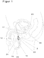
Fig. 1 zeigt einen schematischen Querschnitt durch die Genitalien des Mannes mit der Position des erfindungsgemässen Samenleiterventils im Samenleiter im Bereich des Hodensacks.Fig. 1 shows a schematic cross section through the genitals of the man with the position of the inventive vas deferens in the vas deferens in the region of the scrotum. -
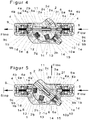
Figur 2 zeigt die Ansicht des erfindungsgemässen Samenleiterventils in geöffneter Stellung, der an den Enden eines durchtrennten Samenleiters angeschlossen ist. Die Flussrichtung der Spermien durch das Samenleiterventil vom testikulären Samenleiterende zum abdominalen Samenleiter ist mit Pfeilen und "Flow" gekennzeichnet.FIG. 2 shows the view of the inventive vas deferens valve in the open position, at the ends of a severed vas deferens connected. The flow direction of the sperm through the vas deferens from the testicular vas deferens to the abdominal vas deferens is indicated by arrows and "flow". -
Figur 3 zeigt das erfindungsgemässe Samenleiterventil an den Samenleiterenden angeschlossen wie inFigur 2 , jedoch in geschlossener Stellung. Die Flussrichtung der Spermien durch den testikulären Samenleiter bis zum Samenleiterventil ist durch die Pfeile und "Flow" bezeichnet. Der Spermienfluss durch den abdominalen Samenleiter ist durch die Schaltwippe in geschlossener Stellung unterbrochen.FIG. 3 shows the inventive vas deferens valve connected to the seminal conductor ends as inFIG. 2 , but in closed position. The flow direction of the sperm through the testicular vas deferens to the spermatic duct valve is indicated by the arrows and "flow". The sperm flow through the abdominal vas deferens is interrupted by the rocker switch in the closed position. -
Figur 4 zeigt einen vertikalen Längsschnitt des Samenleiterventils im geöffneten Zustand.FIG. 4 shows a vertical longitudinal section of the spermatic valve in the open state. -
Figur 5 zeigt einen vertikalen Längsschnitt des Samenleiterventils im geschlossenen Zustand.FIG. 5 shows a vertical longitudinal section of the spermatic valve in the closed state. -
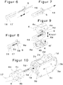
Figur 6 zeigt ein Ventilanschlussstück des Samenleiterventils zum Einstecken in einen Samenleiter.FIG. 6 shows a valve connector of the vas deferens valve for insertion into a vas deferens. -
Figur 7 zeigt das in einen Samenleiter gesteckte Ventilanschlussstück.FIG. 7 shows the plugged into a vas defer valve connector. -
Figur 8 zeigt den Samenleiter mit einem aufgeweiteten Ventilanschlussstück.FIG. 8 shows the vas deferens with a flared valve fitting. -
Figur 9 zeigt zwei Ventilkappenhälften (4) und deren Einbindung mit dem Samenleiter- Ventilanschlussstück- ausFigur 6-8 .FIG. 9 shows two valve cap halves (4) and their integration with the vas deferens valve connectorFigure 6-8 , -
Figur 10 zeigt den Zusammenbau der inFigur 9 entstandenen Kombination von Samenleiter- Ventilanschlussstück und Ventilkappenhälften mit dem Samenleiterventil ausFigur 2 und 3 .FIG. 10 shows the assembly of inFIG. 9 resulting combination of vas deferens valve fitting and valve cap halves with the vas deferens valveFIGS. 2 and 3 ,
In den Figuren sind für dieselben Elemente jeweils dieselben Bezugszeichen verwendet worden und erstmalige Erklärungen betreffen alle Figuren, wenn nicht ausdrücklich anders erwähnt.In the figures, the same reference numerals have been used for the same elements and first explanations apply to all figures, unless expressly stated otherwise.
Das erfindungsgemässe Samenleiterventil 22 lässt sich beim Mann im Scrotum 19 im Samenleiter 16, 17 implantieren wie in der
Die meisten Teile bestehen vorzugsweise aus Implantat-Kunststoff wie (z.B. PEEK) und werden in Mikrospritzgusstechnik und oder CNC-frästechnisch bearbeitet. Die Ventilanschlüsse 9 können aus Metall-Legierungen, wie zum Beispiel Titanlegierungen (z.B. Nitinol) oder einem geeigneten Implantat-Stahl (z.B. Werkstoff 1.4441/316 LVM), oder aus Kunststoff oder aus einer Kombination beider Werkstoffarten gefertigt sein. Es kann aber auch das gitterförmige Röhrchen 9c zum Beispiel aus Metall gefertigt sein und mittels Spritzguss in die zum Beispiel aus Kunststoff bestehenden Teile 9b und 9a eingebunden werden. Die benötigten Druckfedern können aus Implantat- Federstahl oder Platin-Legierungen gefertigt werden.The inventive vas deferens
Most parts are preferably made of implant plastic such as (eg PEEK) and are processed by micro injection molding and or CNC milling. The
Der Ventilkörper 1 besitzt im oberen Drittel in Längsrichtung einen Durchgangskanal 1a von etwa 0,7 mm Durchmesser, der sich durch die Schaltwippe 2 sowie die Ventilanschlusstücke 9 erstreckt und durch den im geöffneten Zustand des Ventils der Spermienfluss stattfinden kann. An den Stirnseiten des quaderförmigen Ventilkörpers, axial zum Durchgangskanal 1a, befinden keilförmige Fräsungen 1d und kreisbahnförmige Fräsungen 1e für die Aufnahme der Ventilkappen 4 und Stufenbohrungen 1b zur Aufnahme der Ventilanschlussstücke 9 während der Implantation. Quer zum Durchgangskanal 1a und von der grossen Planfläche 3 des Ventilkörpers her befindet sich eine, zum Durchgangskanal 1a senkrecht stehende, grosse Stufenbohrung, beispielsweise von 12 mm Durchmesser und einer Tiefe von 5 mm. In der gleichen Achse und im Grund der grossen Stufenbohrung befindet sich eine kleinere Sacklochbohrung, beispielsweise von 2 mm Durchmesser und einer Tiefe von 0,7 mm. Diese kleine Sackbohrung dient der Aufnahme und der drehbaren Lagerung der Schaltwippe 2. Die grosse Stufenbohrung durchschneidet die obere Kante des Ventilkörpers, wodurch die montierte Schaltwippe 2 aus dem Ventilkörper herausragt. Im unteren Bereich der Stufenbohrung befinden sich in der Bohrungswand zwei gleichförmige Aussparungen 1c, die spiegelsymmetrisch zueinander stehen und jeweils mindestens eine Kreissegmentform aufweisen. Sie dienen als Führung und Anschlag einer gefederten Radachse 7, welche die Schaltwippe 2 in die zwei Endstellungen bringt. Die Radachse 7 sorgt für die Umschaltung der Schaltwippe 2. Sie hat die Form einer Hantel. Im Bereich der Achse wird sie mittels der Achsenfeder 13, einer normalen Druckfeder, aus Ihrer Führung in der Schaltwippe 2 gedrückt. Die paarigen Räder an der Achse müssen dadurch automatisch der Form der Aussparungen 1c im Ventilkörper 1 folgen und zwingen so die Schaltwippe 2 in den jeweiligen Endanschlag für "Geöffnet" bzw. "Geschlossen. Das Ventil kann somit nur einen vollends geschlossenen oder vollends geöffneten Zustand einnehmen.The
In der linken unteren Ecke befindet sich im Winkel von beispielsweise 40° zum Durchgangskanal 1a eine durchgehende Stufenbohrung und eine keilförmige Aussparung zur Aufnahme einer Sicherungsvorrichtung, bestehend aus dem Entsicherungsbolzen 10, einer Entsicherungsbolzenfeder 15 und einer Sicherungsplatte 14.
Der quaderförmige Ventilkörper 1 hat durch die Bohrungen und Rundungen eine sichelförmige Hauptoberfläche. Auf dieser schmalen Kante befinden sich mehrere, beispielsweise 6 Stück, zylinderförmige Stifte. Zum Beispiel mittels Ultraschall-Punktschweisstechnik kann so der Ventilkörper 1 mit dem Ventildeckel 3 verbunden werden. Der Ventildeckel 3 schliesst somit die gesamte Ventiltechnik nach aussen hin ab.In the lower left corner is at an angle of for example 40 ° to the passageway 1a a continuous stepped bore and a wedge-shaped recess for receiving a securing device consisting of the
The
Die Schaltwippe 2 hat die Form eines Zylinders geringer Höhe, dessen Zylindermantel den Ventilanschlüssen zugewandt ist sowie einen Zylinderboden und -deckel, die parallel zu den Seitenwänden 3 des Ventilkörpers ausgerichtet sind. Der Zylindermantel der Schaltwippe 2 weist eine Aussparung mit Flächen 2a und 2b auf, die sich über knapp einen Viertel seines Umfangs erstreckt. Die Aussparung in der Schaltwippe 2 besteht somit aus zwei zum Zylinderboden und -deckel senkrecht stehenden Flächen 2a und 2b, die den Winkel der Aussparung, beispielsweise 140° bilden. Die Fläche 2b ist in der geöffneten Position des Ventils 22 bündig mit dem Ventilkörper 1 während die Fläche 2a aus dem Ventilkörper hervorragt. In der geschlossenen Position ist die Fläche 2a bündig mit dem Körper, während Fläche 2b hervorragt. Zudem liegt die Fläche 2a nahe dem testikulären Einlassende des Ventils (das Einlassende des Ventils ist in
Die Schaltwippe 2 ist allseitig abgerundet und weist mehrere Bohrungen auf. Davon führt eine erste Bohrung 2c parallel zum Zylinderdeckel und -boden und durch das Zentrum des Zylinders 2 und parallel zur Fläche 2b. Diese Bohrung ermöglicht das Fliessen von Spermien im Fall eines geöffneten Ventils 22 und nimmt dazu Schieberohre mit einem Aussenfalz 5 und ein Schieberohr mit einem Innenfalz 6 auf, welche von einer Druckfeder 11 nach aussen gedrückt werden. Dadurch entsteht aufgrund der Feder und der passend gewölbten Geometrie der äusseren Stirnflächen der Schieberohre 5 und 6 und dessen Bohrungen 5a und 6a zusammen mit den Durchgangsbohrungen 1a im Ventilkörper und den Bohrung 9a im Ventilanschlussstück 9 ein nach aussen abgedichteter Durchgang für die Spermien im geöffneten Zustand des Samenleiterventils 22. Weitere Bohrungen 2d und 2f verlaufen ebenfalls parallel zum Zylinderdeckel und führen von einer ersten Öffnung am Zylindermantel im Bereich des Einlassendes 4a des Ventils axial mit der gegenüberliegenden Stufenbohrung 2g des Ventils und von einer zweiten senkrechten Bohrung in der Fläche 2a ins Innere der Schaltwippe 2, wobei die Bohrungen 2d und 2f sich an einem Schnittpunkt treffen. Eine weitere Bohrung 2e schneidet diesen Schnittpunkt rechtwinklig zu diesen Bohrungen 2d und 2f und fluchtet mit einer Bohrung an der Seite des Ventils 22, die nach aussen führt. Im geschlossenen Zustand des Samenleiterventils 22 fluchtet die Bohrung 2e auch mit einer Bohrung 3a im Ventildeckel 3 und eben dieser genau gegenüberstehender Bohrung in der Wandung des Ventilkörpers 1. Die vorgenannten Bohrungen dienen der Abführung von Spermien nach aussen bzw. in das Innere des Scrotums 19, im Fall des geschlossenen Ventils.
Die beiden Flächen 2a und 2b bilden die Tastflächen für das Umschalten des Ventils 22. Drückt man auf die Fläche 2b für "Geöffnet", dreht sich die Schaltwippe 2 im Ventilkörper 1 um einen vorgegebenen Winkel, beispielsweise 40°, und rastet an dieser Stelle fix und gefedert ein. Ein Druck auf die andere Fläche 2a für "Geschlossen" lässt die Schaltwippe 2 wieder um 40° in die andere Richtung springen. Die Schaltwippe 2 nimmt in einer Sacklochbohrung 2g einen Absperrbolzen 8 und eine Bolzenfeder 12 als Dichtungselemente auf. Die Bohrungsachse der abgestuften Sacklochbohrung 2g für die Aufnahme des Absperrbolzen 8 und der Bolzenfeder 12 verläuft parallel zur Fläche 2a "Geschlossen" und kreuzt rechtwinklig die Hoch- oder Längsachse der zylinderförmigen Schaltwippe 2. Die Schieberohranordnung mit Bohrungen 5a und 6a liegt um den gleichen vorbestimmten Winkel, z.B. 40°, verdreht zur Bohrungsachse für den Absperrbolzen 8 und damit parallel mit der Fläche 2b "Geöffnet".
In einer weiteren Bohrung 2h, welche diametral zur Fläche 2a und 2b eingebracht ist, befindet sich die Radachsenfeder 13, welche die Radachse 7 aus der Schaltwippe 2 herausdrückt und für den einrastenden Effekt sorgt. Die Radachse 7 wird dazu in genau bemessenen Führungsnuten in der Schaltwippe 2 im Bereich um die Bohrung 2h geführt. Zudem sind an dieser Seite der Schaltwippe 2 im Ventilkörper zwei Aussparungen 1c angeordnet, in denen die gefederte Radachse 7 mit geringem Spiel und genau bemessenen Verschiebeweg aufgenommen wird. Die Aussparungen sind an ihren den Anschlussstücken zugewandten Seiten kreissegmentförmig ausgebildet, sodass die Radachse 7 dort arretiert wird. An ihren, der Mitte des Ventils zugewandten Seite weisen die Aussparungen 1c je eine nach oben zur Schaltwippe 2 hin gewinkelte Fläche auf, die sich in der Mittellinie des Ventils 22 treffen.The
The
The two
In a
Dabei wird die Radachse 7 in der geschlossenen Ventilstellung in der auslassseitigen Aussparung 1c aufgenommen (in der Figur auf der linken Seite), wobei sie bei Umschaltung des Ventils 22 in die einlass-seitige Aussparung 1c bewegt wird und dort aufgenommen wird (in der Figur auf der rechten Seite). Das Schieberohr mit Aussenfalz 5 und das Schieberohr mit Innenfalz 6, die in der Schaltwippe 2 montiert werden, sind so gefertigt, dass sie ineinander gesteckt werden können und dabei mittels der Druckfeder 11, einer normalen Druckfeder, auseinandergedrückt werden. Das bewirkt ein Abdichten des Durchgangskanals 5a und 6a zum Durchgangskanal 1a des Ventilkörpers 1. Die nach aussen ragenden Enden der Schieberohre besitzen dazu noch zusätzlich eine gewölbte Geometrie, die der Form der grossen Stufenbohrung im Ventilkörper 1 entspricht. Ist das Ventil geöffnet, verläuft die Schieberohranordnung in gleicher Achse mit dem Ventildurchgang. Wird das Ventil durch eine -40° Drehung der Schaltwippe 2 geschlossen, zeigt die Öffnung eines Schieberohrs nach aussen ins Freie. Das andere Schieberohr rastet rechts unten in die Bohrung der Sicherungsplatte 14 ein. Soll das Ventil geschlossen werden, muss erst der Entsicherungsbolzen von unten aussen gegen den Widerstand einer Entsicherungsbolzenfeder 15 gedrückt werden. Erst dann kann gleichzeitig das Ventil geöffnet werden. Der Entsicherungsbolzen 10 weist, wie die Schieberohre, eine Durchgangsbohrung 10a auf und erlaubt eine Vereinnahmung der Hohlräume durch die umgebene Körperflüssigkeit der Schieberohre im geschlossenen Zustand des Ventils. Eine Sicherungsplatte 14 ist ein mit einer Trapezform versehenes, nach innen gewölbtes und mit einer Stufenbohrung ausgeführtes Plättchen und wird bei der Montage des Ventils nach dem Einführen des Entsicherungsbolzens 10 und der Entsicherungsbolzenfeder 15 in die passende Aussparung im Ventilkörper 1 geschoben. Die Entsicherungsbolzenfeder 15 kann als mehrteilige Tellerfeder oder als normale Druckfeder ausgeführt werden. Mit der Variante der Tellerfedern lässt sich so ein Klick-Effekt erzielen, der das Entsichern des Entsicherungsbolzens 10 anzeigt.
Die eigentliche Abdichtung des Spermienflusses, durch das geschlossene Ventil, wird vom Absperrbolzen 8 gewährleistet. Beim Schliessen des Ventils schiebt sich dieser vor das abdominale Durchgangsloch im Ventilinneren, also die Auslassöffnung des Ventils im Bereich dessen Auslassendes. Entsprechend ist das Auslassende in
Für ein Spermium mit einem Kopfdurchmesser von etwa 3,5 Mikrometer ist diese Barriere unüberwindbar. Zumal sich die Spermien im Bereich des Samenleiters noch in einer Säuresperre befinden, also sich nicht selbst bewegen können.In this case, the
The actual sealing of the sperm flow, through the closed valve, is ensured by the locking
For a sperm with a head diameter of about 3.5 microns, this barrier is insurmountable. Especially as the sperm are in the area of the spermatic duct still in an acid barrier, so can not move itself.
Als Drehachse, genau im Mittelpunkt der Schaltwippe 2, dient je ein zylinderförmiger Zapfen (nicht dargestellt) auf beiden Seiten der Schaltwippe 2, welcher aus der Oberfläche des Zylinderdeckels bzw. -bodens herausragt. Die Zapfen passen in die (nicht dargestellten) Sacklochbohrungen des Ventilkörpers auf der einen Seite und in die Sacklochbohrung des Ventildeckels 3 auf der anderen Seite.
Der Ventildeckel 3 ist im Prinzip ein Spiegelbild der grossen Seitenwand des Ventilkörpers. Er verschliesst die ganze Mechanik nach der Montage nach aussen hin ab. Er besitzt dazu noch mehrere, zum Beispiel 6 Löcher 3b zur Aufnahme entsprechender Stifte am Ventilkörper 1, um mit diesem passgenau verschweisst werden zu können. Alternativ könnte der Ventildeckel 3 aber auch mit dem Ventilkörper 1 verschraubt oder mittels Einrasttechnik mit dem Ventilkörper 1 verbunden werden.As a rotation axis, exactly in the center of the
The
Wie in den
So lässt sich das Ventilanschlussstück 9 mit minimalem Aussendurchmesser leicht in das kleine Lumen des Samenleiters stecken. Mittels einer nicht dargestellten Spezialzange, die dem Prinzip einer Blindnietzange entspricht, wird Element 18 aus dem Ventilanschlussstück 9 gezogen und weitet das Lumen des Ventilanschlusses im Bereich der Gitterstruktur zusammen mit dem Samenleiter 16, 17 selbst leicht auf.Thus, the
Eine weitere Variante des Aufweitens der Gitterstruktur des Ventilanschlussstückes 9 ist auch möglich mit dem umgekehrten Prinzip durch das Einpressen eines zylinderförmigen Dorns mit kegelförmiger Spitze anstelle des dargestellten Elements 18 mit Hilfe einer ebenfalls nicht dargestellten ähnlichen Spezialzange.A further variant of the widening of the lattice structure of the
Die hohlzylinderförmigen Ventilkappen 4 schützen durch ihre wulstige abgerundete Form die Samenleiter 16, 17 vor einem Einstechen der Ventilanschlüsse bei extremen Bewegungen. Die Mantelflächen der Ventilkappen 4 sind ringsherum mit Bohrungen 4b versehen, durch die die Samenleiterenden stets mit dem natürlichen Fluidum des umliegenden Gewebes in Kontakt bleiben und der Stoffwechsel ermöglicht wird. Eine Ventilkappe 4 besteht aus zwei Hälften, die mit Widerhaken 4d und Aussparungen versehen sind. Mit deren Hilfe lassen sich die beiden Hälften zusammen stecken und gleichzeitig das Ventilanschlüsstück 9 darin befestigen.The hollow cylindrical valve caps 4 protect by their beaded rounded shape the vas deferens 16, 17 before a piercing of the valve ports in extreme movements. The lateral surfaces of the valve caps 4 are provided around with
Zusammengesteckt bilden die beiden Hälften einen Hohlzylinder. Er hat auf der Seite zum Samenleiter 16, 17 hin eine grosse, abgerundete Kante und eine nach innen gerichtete Wulst. Der Innendurchmesser der Wulst sollte dem Aussendurchmesser des Samenleiters entsprechen. Zum Ventil hin besitzen die Ventilkappen 4 im Innem eine Nut 4a zur Aufnahme eines Flanches 9b des Ventilanschlusses 9. Dazu wird eine nicht dargestellte Spezialzange benutzt, die mit einer Aufnahmevorrichtung für die Ventikappenhälften 4 versehen ist. Damit lassen sich die beiden Hälften sicher, exakt und kraftvoll zusammendrücken. Die Ventikappenhälften 4 rasten ineinander ein.Plugged together, the two halves form a hollow cylinder. He has on the side of the vas deferens 16, 17 towards a large, rounded edge and an inwardly directed bead. The inside diameter of the bead should correspond to the outside diameter of the vas deferens. Towards the valve, the valve caps 4 have in the interior a
Des Weiteren sind in den Hälften Mikronadeln 4e eingearbeitet. Sie sind so angeordnet, dass sie beim Zusammendrücken der Ventilkappenhälften die muskulösen Wandungen des Samenleiters tangential durchstechen und in eingearbeitete Löcher auf der gegenüberliegenden Ventilkappenhälfte 4 einstechen, ohne dabei auf der anderen Seite auszutreten. Dies sorgt für eine sichere Verbindung des Samenleiterventils mit dem Samenleiter 16, 17, ohne die Blutversorgung des Samenleiters durch eine Abbindung oder sonstigen Naht einzuschränken oder zu gefährden. Der grosse Flansch des Ventilanschlussstückes 9 bettet sich dabei in die Innennut 4a der Ventilkappenhälften 4 ein.
Die so entstandene Einheit aus Anschlussstück 9, Samenleiter 16, 17 und Ventilkappenhälften 4 wird abschliessend in das Samenleiterventil gesteckt. Sie rastet dort ebenfalls dank der Widerhaken 4f in die Einrastelemente 1d und der kreisnutförmigen Aussparung 1e des Ventilkörpers 1 ein. Die beschriebenen Schritte in den
Vorzugsweise werden für das erfindungsgemässe Samenleiterventil inerte Materialien verwendet. Dadurch bedürfen die Oberflächen der Einzelteile keiner Antihaftbeschichtungen und Medikamente zur Vermeidung von Abstossungsreaktionen des menschlichen Körpers.
In einer Ausführung der Erfindung ist eine auf Einzelteile beschränkte oder auf alle Teile des Samenleiterventils 22 ausgeweitete Oberflächenbehandlung zum vorgenannten Zweck optional gegeben. Furthermore, in the halves microneedles 4e are incorporated. They are arranged so that they tangentially pierce the muscular walls of the vas deferens when squeezing the valve cap halves and pierce in holes machined on the opposite
The resulting unit of fitting 9, vas deferens 16, 17 and valve cap halves 4 is finally inserted into the vas deferens valve. There it also engages thanks to the
Preferably, inert materials are used for the inventive vas deferens valve. As a result, the surfaces of the individual parts require no non-stick coatings and drugs to avoid rejection reactions of the human body.
In one embodiment of the invention, a surface-treatment limited to individual parts or extended to all parts of the vas deferens
Um auf die unterschiedlichen anatomischen Dimensionen der Samenleiter 16, 17 verschiedener Männer reagieren zu können, sind die Ventilanschlüsse 9 und Ventilkappen 4 entsprechend unterschiedlich gross gefertigt. So kann der Chirurg bei der Implantation die passende Grösse wählen. Der Ventilkörper 1 selbst, mit den inliegenden Teilen, könnte dabei immer gleich gross bleiben. Somit eignet sich eine Implantation des erfindungsgemässen Samenleiterventils auch als Alternative für eine Vasovasostomie, wenn beide Samenleiterenden 16,17 eines Samenleiters unterschiedliche Dimensionen aufweisen, wie es sich nach vor Jahren erfolgter Vasektomie oft darstellt.In order to be able to react to the different anatomical dimensions of the vas deferens 16, 17 of different men, the
Mit dem Schliessen des Samenleiterventils ist der Anwender nicht sofort, sondern erst nach Wochen bis Monaten, steril. Dies braucht nicht als Nachteil gelten. Wird z.B. in einer Partnerschaft mit Kinderwunsch die Schwangerschaft erreicht, wird das Ventil geschlossen. Spätestens mit der Geburt des Kindes, also in der Regel etwa nach 9 Monaten nach der Empfängnis, ist der Anwender dann steril. Weitere Kontrazeptiva seitens der Frau oder des Mannes werden nicht mehr benötigt. Erst wenn ein erneuter Kinderwunsch besteht, z.B. nach 2-4 Jahren, werden die Samenleiterventile geöffnet. Dann geht es schneller. So konnten z.B. nach 4 Wochen bzw. schon bei der ersten Ejakulationen nach Implantation des neuentwickelten Samenleiterventils Spermien im Ejakulat nachgewiesen werden, obwohl zuvor eine einjährige Sterilität vorlag.With the closure of the vas deferens the user is not immediately, but only after weeks to months, sterile. This does not have to be considered a disadvantage. If e.g. In a partnership with the desire to conceive, the valve is closed. At the latest with the birth of the child, so usually about 9 months after conception, the user is then sterile. Other contraceptives from the woman or the man are no longer needed. Only when there is a new desire for a child, e.g. after 2-4 years, the vas deferens are opened. Then it's faster. For example, sperm are detected in the ejaculate after 4 weeks or already at the first ejaculations after implantation of the newly developed vas deferens valve, even though a one-year sterility was previously present.
Bis auf das Kondom haben alle Kontrazeptiva für den Mann, einschliesslich der medikamentösen Mittel und auch die hiermit beschriebene Erfindung, den Nachteil, dass der Anwender nicht sofort nach dem Aktivieren der Absperrfunktion oder der Einnahme des Medikaments steril ist. Es können sich noch wochen- bis monatelang Spermien in den, der jeweiligen Vorrichtung nachfolgenden Organe, wie der Vorsteherdrüse 25 (Prostata)und der Bläschendrüse 26 (Glandulae vesiculosa) aufhalten und mit einer Ejakulation während eines Koitus hervorgebracht eine unerwünschte Befruchtung auslösen.
Deshalb ist es ratsam die gewünschte Sterilität zuvor mittels eines Spermiogrammes wissenschaftlich bestätigen zu lassen.
Ausserdem schützen diese Methoden nicht vor Infektionskrankheiten.Except for the condom, all male contraceptives, including the medicines and also the invention described herein, have the disadvantage that the user is not sterile immediately after activating the occlusion function or taking the medication. Sperm may persist for weeks or even months in the organs following the respective device, such as the prostate gland 25 and the seminal vesicle 26 (glandulae vesiculosa) and produce an undesired fertilization with ejaculation during coitus.
Therefore, it is advisable to have the desired sterility previously confirmed by a spermiogram scientifically.
In addition, these methods do not protect against infectious diseases.
-
1 Ventilkörper1 valve body
- 1a Durchgangskanal im Ventilkörper1a through-channel in the valve body
-
1b Bohrung im Ventilkörper für Aufnahme Ventilanschlussstück 91b bore in the valve body for receiving
valve connector 9 - 1c Aussparungen im Ventilkörper zur Arretierung der Radachse 71 c recesses in the valve body for locking the wheel axle. 7
-
1d Aussparung im Ventilkörper zur Einrastung der Ventilkappe 41d recess in the valve body for latching the
valve cap 4 - 1e Aussparung im Ventilkörper zur Aufnahme der Ventilkappe 41e recess in the valve body for receiving the valve cap. 4
-
2 Schaltwippe
- 2a Schaltfläche der Schaltwippe zum Verschliessen des Ventils 22
- 2b Schaltfläche der Schaltwippe zum Öffnen des Ventils 22
- 2c Bohrung der Schaltwippe zur Aufnahme der Schieberohre 5+6
- 2d Bohrung in der Schaltfläche 2a zur Abführung der Spermien
- 2e Bohrung durch die Schaltwippe zur Abführung der Spermien
- 2f Bohrung in der Schaltwippenkante zur Abführung der Spermien
- 2g Bohrung der Schaltwippe zur Aufnahme des Absperrbolzens 8
- 2h Bohrung und Aussparung zur Aufnahme der Radachse 7 und Feder 13
- 2a Button of the rocker switch for closing the
valve 22 - 2b button of the rocker switch to open the
valve 22 - 2c bore of the rocker switch to accommodate the
slide tubes 5 + 6 - 2d hole in button 2a for the removal of sperm
- 2e bore through the rocker switch to remove the sperm
- 2f bore in the paddle edge for the removal of sperm
- 2g bore of the rocker switch to receive the shut-off
bolt 8 - 2h bore and recess for receiving the
wheel axle 7 and spring 13th
-
3 Ventildeckel
- 3a Bohrung im Ventildeckel zur Abführung der Spermien
- 3b Bohrung / Schweisspunkt zum Verbinden Ventildeckel und -körper
- 3c Kennzeichnung der Fliessrichtung am Ventildeckel
- 3a hole in the valve cover for the removal of sperm
- 3b bore / weld point for connecting valve cover and body
- 3c Identification of the direction of flow at the valve cover
-
4 Ventilkappe
- 4a Nut in der Ventilkappe zur Aufnahme des Flansches 9b des Ventilanschlussstücks 9
- 4b Bohrungen in der Ventilkappe als Verbindung des eingeschlossenen Samenleiters nach aussen
- 4c Bohrungen in der Ventilkappe zur Aufnahme der Mikronadel 4e der gegenseitigen Ventilkappenhälfte
- 4d Widerhaken zum Ineinanderrasten der Ventilkappenhälften
- 4e Mikronadeln in den Ventilkappenhälften
- 4f Widerhaken zum Einrasten der Ventilkappe 4 in den Ventilkörper 1
- 4a groove in the valve cap for receiving the
flange 9b of the valve fitting 9th - 4b holes in the valve cap as a connection of the enclosed vas deferens to the outside
- 4c Holes in the valve cap for receiving the microneedle 4e of the mutual valve cap half
- 4d barbs for latching the valve caps
- 4e microneedles in the valve cap halves
- 4f Barb for engaging the
valve cap 4 in the valve body. 1
-
5 Schieberohr mit Aussenfalz
- 5a Durchgangskanal im Schieberohr mit Aussenfalz
- 5a Through-channel in sliding tube with external rebate
-
6 Schieberohr mit Innenfalz
- 6a Durchgangskanal im Schieberohr mit Innenfalz
- 6a Passage channel in the sliding tube with inner rebate
- 7 Radachse7 wheel axle
- 8 Absperrbolzen8 stop pins
-
9 Ventilanschlussstück
- 9a Durchgangskanal im Ventilanschlussstück
- 9b Flansch am Ventilanschlussstück
- 9c Durchgangsröhrchen mit Gitterstruktur am Ventilanschlussstück
- 9a through-channel in valve connection piece
- 9b Flange on the valve connector
- 9c passage tube with lattice structure on valve connection piece
-
10 Entsicherungsbolzen
- 10a Durchgangskanal im Entsicherungsbolzen
- 10a passage in the release bolt
- 11 Schieberohrfeder11 sliding ear spring
- 12 Bolzenfeder12 bolt spring
- 13 Radachsenfeder13 wheel axle spring
- 14 Sicherungsplatte14 securing plate
- 15 Entsicherungsbolzenfeder15 Entsicherungsbolzenfeder
- 16 Samenleiterende testikulär16 vas deferens testicular
- 17 Samenleiterende abdominal17 vas deferens abdominal
-
18 nagelartiges Element zum Aufweiten des Durchgangsröhrchens 9c18 nail-like element for expanding the
passage tube 9c - 19 Hodensack (Scrotum)19 scrotum
- 20 Hoden (Testis)20 testes (Testis)
- 21 Nebenhoden (Epididymis)21 Epididymis
- 22 Samenleiterventil (komplett / allgemein)22 spermatic valve (complete / general)
- 23 Bläschendrüse (Glandulae vesiculosae)23 vesicular gland (Glandulae vesiculosae)
- 24 Vorsteherdrüse (Prostata)24 prostate gland
Claims (17)
- An implantable vas deferens valve (22) for contraception for use by the male human or male animal to regulate sperm flow in the abdominal vas deferens (17) or vas deferens within the scrotum (19), having a valve (22) that can be fastened by means of valve connectors (9) to the testicular and abdominal end of a severed vas deferens (16, 17), and having a manual switch for changing the state of the valve, the switching state of which is detectable from the outside by palpation and changeable between an open and closed state and the vas deferens valve (22) has a through-passage (1a, 5a, 6a, 9a), which in the opened state of the vas deferens valve (22) leads from the valve connector (9) on the testicular vas deferens (16) to the valve connector (9) at the abdominal end of the vas deferens (17), and in the closed valve state of the vas deferens valve (22) can be shut off at the end of the through-passage (1a) which faces the abdominal vas deferens end (17), characterized in that
the vas deferens valve (22) has at least one outflow channel (2d, 2e, 2f, 3a), which in the closed state of the valve (22) leads from the valve connector (9) at the testicular end of the vas deferens (16) out of the vas deferens valve (22) to the outside and into the body of the user. - Implantable vas deferens valve (22) according to claim 1, characterized in that the switch is designed as a rocker switch (2).
- Implantable vas deferens valve (22) according to claim 1, characterized in that the through-passage (5a, 6a) in the region of the switch (2) is arranged in a sliding tube with an inner fold (5) and an outer fold (6) and a compression spring (11).
- Implantable vas deferens valve (22) according to claim 1, characterized in that the rocker switch (2) has a shut-off pin (8) with spring (12) for shutting off the through-passage (1a) at the outlet end of the vas deferens valve (22).
- Implantable vas deferens valve (22) according to claim 1, characterized in that the rocker switch (2) has a wheel axle (7) with spring (13) and recesses (2h) for receiving the wheel axle (7) in a latching manner.
- Implantable vas deferens valve (22) according to claim 1, characterized in that a release bolt (10) with a release bolt spring (15) is arranged on the rocker switch (2).
- Implantable vas deferens valve (22) according to claim 1, characterized in that the release bolt (10) has openings leading out of the valve body (1) of the vas deferens valve (22).
- Implantable vas deferens valve (22) according to claim 1, characterized in that the vas deferens valve (22) has valve connectors (9) for receiving the vas deferens ends (16, 17) with a tube (9c), the wall of which has outside conical graduations.
- Implantable vas deferens valve (22) according to claim 1, characterized in that the vas deferens valve (22) has valve connectors (9) for receiving the vas deferens ends (16, 17) with a tube (9c), the wall of which is provided with a lattice structure.
- Implantable vas deferens valve (22) according to claim 8 or 9, characterized in that valve connectors (9) are accommodated in valve caps (4) of the vas deferens valve (22).
- Implantable vas deferens valve (22) according to claim 10, characterized in that microneedles (4e) are arranged in the valve caps (4) for attachment of the valve caps (4) on the walls of the vas deferens (16, 17).
- Implantable vas deferens valve (22) according to claim 11, characterized in that the valve caps (4) have bores (4b) which lead to the outside and ensure contact of the vas deferens (16, 17) with body fluid.
- Implantable vas deferens valve (22) according to claim 10, characterized in that the valve caps (4) have internal grooves (4a) for receiving the valve connectors (9).
- Implantable vas deferens valve (22) according to claim 10, characterized in that the valve caps (4) consist of two mutually attachable halves each.
- Implantable vas deferens valve (22) according to claim 8 or 9, characterized in that the valve connectors (9) of the vas deferens valve (22) are made of metal alloys or plastic or of a combination of both types of material.
- Implantable vas deferens valve (22) according to claim 9, characterized in that the lattice structure of the tube (9c) is completely or partially coated with silicone or an elastic inert material.
- Implantable vas deferens valve (22) according to one of the preceding claims 1 to 16, characterized in that individual parts of the vas deferens valve or the entire vas deferens valve (22) are coated with drugs or non-stick coatings.
Applications Claiming Priority (2)
| Application Number | Priority Date | Filing Date | Title |
|---|---|---|---|
| CH00542/14A CH709505A2 (en) | 2014-04-08 | 2014-04-08 | Device for contraception for use in man. |
| PCT/IB2015/052224 WO2015155618A1 (en) | 2014-04-08 | 2015-03-26 | Device for contraception for use by a man |
Publications (3)
| Publication Number | Publication Date |
|---|---|
| EP3128965A1 EP3128965A1 (en) | 2017-02-15 |
| EP3128965B1 EP3128965B1 (en) | 2018-05-02 |
| EP3128965B9 true EP3128965B9 (en) | 2018-11-21 |
Family
ID=53059363
Family Applications (1)
| Application Number | Title | Priority Date | Filing Date |
|---|---|---|---|
| EP15721317.4A Active EP3128965B9 (en) | 2014-04-08 | 2015-03-26 | Device for contraception for use by a man |
Country Status (6)
| Country | Link |
|---|---|
| US (1) | US10034794B2 (en) |
| EP (1) | EP3128965B9 (en) |
| CH (1) | CH709505A2 (en) |
| ES (1) | ES2676756T3 (en) |
| HU (1) | HUE039485T2 (en) |
| WO (1) | WO2015155618A1 (en) |
Families Citing this family (2)
| Publication number | Priority date | Publication date | Assignee | Title |
|---|---|---|---|---|
| US20180166417A1 (en) * | 2016-12-13 | 2018-06-14 | Nanya Technology Corporation | Wafer level chip-on-chip semiconductor structure |
| CN112006834A (en) * | 2019-05-28 | 2020-12-01 | 曾均 | Contraceptive ring capable of being pressed by pulling |
Family Cites Families (6)
| Publication number | Priority date | Publication date | Assignee | Title |
|---|---|---|---|---|
| US4200107A (en) | 1977-11-16 | 1980-04-29 | Reid Robert L | Vascular connector for effecting vascular duct closure and permitting vascular re-opening |
| KR100252182B1 (en) | 1998-02-23 | 2000-07-01 | 윤종용 | Hdd and its tracking method |
| DE19909427C1 (en) * | 1999-02-23 | 2000-05-25 | Bimek Clemens | Contraceptive semen blocker for men has valve positioned in sperm duct and actuated by external pressure |
| WO2002041933A2 (en) | 2000-11-22 | 2002-05-30 | Shepherd Medical Company | Method and device for vas occlusion |
| EP2346456B1 (en) | 2008-10-10 | 2021-04-07 | Implantica Patent Ltd. | An apparatus for temporary male contraception |
| US8616212B1 (en) | 2011-11-15 | 2013-12-31 | John R. Logan | Vas deferens or fallopian tubes valve system |
-
2014
- 2014-04-08 CH CH00542/14A patent/CH709505A2/en not_active Application Discontinuation
-
2015
- 2015-03-26 US US15/302,471 patent/US10034794B2/en active Active
- 2015-03-26 ES ES15721317.4T patent/ES2676756T3/en active Active
- 2015-03-26 HU HUE15721317A patent/HUE039485T2/en unknown
- 2015-03-26 EP EP15721317.4A patent/EP3128965B9/en active Active
- 2015-03-26 WO PCT/IB2015/052224 patent/WO2015155618A1/en active Application Filing
Also Published As
| Publication number | Publication date |
|---|---|
| US20170020719A1 (en) | 2017-01-26 |
| WO2015155618A1 (en) | 2015-10-15 |
| US10034794B2 (en) | 2018-07-31 |
| ES2676756T9 (en) | 2019-01-02 |
| EP3128965B1 (en) | 2018-05-02 |
| HUE039485T2 (en) | 2019-01-28 |
| ES2676756T3 (en) | 2018-07-24 |
| CH709505A2 (en) | 2015-10-15 |
| EP3128965A1 (en) | 2017-02-15 |
Similar Documents
| Publication | Publication Date | Title |
|---|---|---|
| DE4331658B4 (en) | Implantable device for selectively opening and closing tubular body organs, in particular the urethra | |
| EP0741587B1 (en) | Implantable dosaging system | |
| DE3821631C2 (en) | ||
| EP0144699B1 (en) | Device for the alternative opening and closing of tubulaire body organs, especially of the urethra | |
| EP0810001B1 (en) | Device for treating male and female bladder emptying disorders | |
| DE2005167C3 (en) | Postoperative drainage tube | |
| DE3020991C2 (en) | ||
| DE4412947C2 (en) | Penis elevator | |
| DE3802010C2 (en) | ||
| EP0867196A2 (en) | Catheter system for transdermal passages | |
| DE602004013072T2 (en) | Needle guard with features for guiding a probe | |
| DE60223268T2 (en) | PUNCHING PLUG AND METHOD OF INSTALLING THEM | |
| EP3128965B9 (en) | Device for contraception for use by a man | |
| DE19909427C1 (en) | Contraceptive semen blocker for men has valve positioned in sperm duct and actuated by external pressure | |
| DE19733665C2 (en) | Device for combined urine drainage and catheterization of incontinent males | |
| DE2438691A1 (en) | Implantable prosthetic clamp - with compressible fluid reservoir connected to three arm jaw with fluid actuator | |
| DE60203815T2 (en) | Device for selective closure in a catheter | |
| DE2913036A1 (en) | Claw-type sterilisation pessary - is inserted solely from womb using hysteroscopy procedure | |
| DE19712908C2 (en) | Catheter lock clamp | |
| DE19915342C1 (en) | Urological catheter plug in the form of a valve device | |
| DE10217787C1 (en) | Closure insert for male urinary passage has flexible closed tube inserted into urethra as contraceptive | |
| AT507502B1 (en) | SELF-CLASS MEDICAL FINAL ENGINE | |
| WO2016062418A1 (en) | Peg probe having protected manual valve operation | |
| DE60106888T2 (en) | DEVICE FOR REDUCING ANAL PAIN | |
| DE2328175A1 (en) | TUBE OCCLUSIVE PESSARY AND DEVICE FOR SETTING THE TUBE OCCLUSIVE PESSARY |
Legal Events
| Date | Code | Title | Description |
|---|---|---|---|
| STAA | Information on the status of an ep patent application or granted ep patent |
Free format text: STATUS: THE INTERNATIONAL PUBLICATION HAS BEEN MADE |
|
| PUAI | Public reference made under article 153(3) epc to a published international application that has entered the european phase |
Free format text: ORIGINAL CODE: 0009012 |
|
| STAA | Information on the status of an ep patent application or granted ep patent |
Free format text: STATUS: REQUEST FOR EXAMINATION WAS MADE |
|
| 17P | Request for examination filed |
Effective date: 20161031 |
|
| AK | Designated contracting states |
Kind code of ref document: A1 Designated state(s): AL AT BE BG CH CY CZ DE DK EE ES FI FR GB GR HR HU IE IS IT LI LT LU LV MC MK MT NL NO PL PT RO RS SE SI SK SM TR |
|
| AX | Request for extension of the european patent |
Extension state: BA ME |
|
| DAV | Request for validation of the european patent (deleted) | ||
| DAX | Request for extension of the european patent (deleted) | ||
| RIC1 | Information provided on ipc code assigned before grant |
Ipc: A61F 6/20 20060101AFI20171004BHEP Ipc: A61F 6/24 20060101ALN20171004BHEP |
|
| GRAP | Despatch of communication of intention to grant a patent |
Free format text: ORIGINAL CODE: EPIDOSNIGR1 |
|
| STAA | Information on the status of an ep patent application or granted ep patent |
Free format text: STATUS: GRANT OF PATENT IS INTENDED |
|
| INTG | Intention to grant announced |
Effective date: 20171122 |
|
| GRAS | Grant fee paid |
Free format text: ORIGINAL CODE: EPIDOSNIGR3 |
|
| GRAA | (expected) grant |
Free format text: ORIGINAL CODE: 0009210 |
|
| STAA | Information on the status of an ep patent application or granted ep patent |
Free format text: STATUS: THE PATENT HAS BEEN GRANTED |
|
| AK | Designated contracting states |
Kind code of ref document: B1 Designated state(s): AL AT BE BG CH CY CZ DE DK EE ES FI FR GB GR HR HU IE IS IT LI LT LU LV MC MK MT NL NO PL PT RO RS SE SI SK SM TR |
|
| REG | Reference to a national code |
Ref country code: GB Ref legal event code: FG4D Free format text: NOT ENGLISH |
|
| REG | Reference to a national code |
Ref country code: CH Ref legal event code: EP Ref country code: AT Ref legal event code: REF Ref document number: 994436 Country of ref document: AT Kind code of ref document: T Effective date: 20180515 |
|
| REG | Reference to a national code |
Ref country code: DE Ref legal event code: R096 Ref document number: 502015004139 Country of ref document: DE Ref country code: IE Ref legal event code: FG4D Free format text: LANGUAGE OF EP DOCUMENT: GERMAN |
|
| GRAT | Correction requested after decision to grant or after decision to maintain patent in amended form |
Free format text: ORIGINAL CODE: EPIDOSNCDEC |
|
| REG | Reference to a national code |
Ref country code: ES Ref legal event code: FG2A Ref document number: 2676756 Country of ref document: ES Kind code of ref document: T3 Effective date: 20180724 |
|
| REG | Reference to a national code |
Ref country code: NL Ref legal event code: FP |
|
| REG | Reference to a national code |
Ref country code: SE Ref legal event code: TRGR |
|
| REG | Reference to a national code |
Ref country code: LT Ref legal event code: MG4D |
|
| PG25 | Lapsed in a contracting state [announced via postgrant information from national office to epo] |
Ref country code: BG Free format text: LAPSE BECAUSE OF FAILURE TO SUBMIT A TRANSLATION OF THE DESCRIPTION OR TO PAY THE FEE WITHIN THE PRESCRIBED TIME-LIMIT Effective date: 20180802 Ref country code: FI Free format text: LAPSE BECAUSE OF FAILURE TO SUBMIT A TRANSLATION OF THE DESCRIPTION OR TO PAY THE FEE WITHIN THE PRESCRIBED TIME-LIMIT Effective date: 20180502 Ref country code: NO Free format text: LAPSE BECAUSE OF FAILURE TO SUBMIT A TRANSLATION OF THE DESCRIPTION OR TO PAY THE FEE WITHIN THE PRESCRIBED TIME-LIMIT Effective date: 20180802 Ref country code: LT Free format text: LAPSE BECAUSE OF FAILURE TO SUBMIT A TRANSLATION OF THE DESCRIPTION OR TO PAY THE FEE WITHIN THE PRESCRIBED TIME-LIMIT Effective date: 20180502 |
|
| REG | Reference to a national code |
Ref country code: CH Ref legal event code: PK Free format text: BERICHTIGUNG B9 |
|
| PG25 | Lapsed in a contracting state [announced via postgrant information from national office to epo] |
Ref country code: RS Free format text: LAPSE BECAUSE OF FAILURE TO SUBMIT A TRANSLATION OF THE DESCRIPTION OR TO PAY THE FEE WITHIN THE PRESCRIBED TIME-LIMIT Effective date: 20180502 Ref country code: HR Free format text: LAPSE BECAUSE OF FAILURE TO SUBMIT A TRANSLATION OF THE DESCRIPTION OR TO PAY THE FEE WITHIN THE PRESCRIBED TIME-LIMIT Effective date: 20180502 Ref country code: GR Free format text: LAPSE BECAUSE OF FAILURE TO SUBMIT A TRANSLATION OF THE DESCRIPTION OR TO PAY THE FEE WITHIN THE PRESCRIBED TIME-LIMIT Effective date: 20180803 Ref country code: LV Free format text: LAPSE BECAUSE OF FAILURE TO SUBMIT A TRANSLATION OF THE DESCRIPTION OR TO PAY THE FEE WITHIN THE PRESCRIBED TIME-LIMIT Effective date: 20180502 |
|
| REG | Reference to a national code |
Ref country code: HU Ref legal event code: AG4A Ref document number: E039485 Country of ref document: HU |
|
| PG25 | Lapsed in a contracting state [announced via postgrant information from national office to epo] |
Ref country code: EE Free format text: LAPSE BECAUSE OF FAILURE TO SUBMIT A TRANSLATION OF THE DESCRIPTION OR TO PAY THE FEE WITHIN THE PRESCRIBED TIME-LIMIT Effective date: 20180502 Ref country code: DK Free format text: LAPSE BECAUSE OF FAILURE TO SUBMIT A TRANSLATION OF THE DESCRIPTION OR TO PAY THE FEE WITHIN THE PRESCRIBED TIME-LIMIT Effective date: 20180502 Ref country code: RO Free format text: LAPSE BECAUSE OF FAILURE TO SUBMIT A TRANSLATION OF THE DESCRIPTION OR TO PAY THE FEE WITHIN THE PRESCRIBED TIME-LIMIT Effective date: 20180502 Ref country code: SK Free format text: LAPSE BECAUSE OF FAILURE TO SUBMIT A TRANSLATION OF THE DESCRIPTION OR TO PAY THE FEE WITHIN THE PRESCRIBED TIME-LIMIT Effective date: 20180502 |
|
| REG | Reference to a national code |
Ref country code: DE Ref legal event code: R097 Ref document number: 502015004139 Country of ref document: DE |
|
| PG25 | Lapsed in a contracting state [announced via postgrant information from national office to epo] |
Ref country code: SM Free format text: LAPSE BECAUSE OF FAILURE TO SUBMIT A TRANSLATION OF THE DESCRIPTION OR TO PAY THE FEE WITHIN THE PRESCRIBED TIME-LIMIT Effective date: 20180502 |
|
| PLBE | No opposition filed within time limit |
Free format text: ORIGINAL CODE: 0009261 |
|
| STAA | Information on the status of an ep patent application or granted ep patent |
Free format text: STATUS: NO OPPOSITION FILED WITHIN TIME LIMIT |
|
| 26N | No opposition filed |
Effective date: 20190205 |
|
| PG25 | Lapsed in a contracting state [announced via postgrant information from national office to epo] |
Ref country code: SI Free format text: LAPSE BECAUSE OF FAILURE TO SUBMIT A TRANSLATION OF THE DESCRIPTION OR TO PAY THE FEE WITHIN THE PRESCRIBED TIME-LIMIT Effective date: 20180502 |
|
| PGFP | Annual fee paid to national office [announced via postgrant information from national office to epo] |
Ref country code: HU Payment date: 20190306 Year of fee payment: 5 |
|
| PG25 | Lapsed in a contracting state [announced via postgrant information from national office to epo] |
Ref country code: MC Free format text: LAPSE BECAUSE OF FAILURE TO SUBMIT A TRANSLATION OF THE DESCRIPTION OR TO PAY THE FEE WITHIN THE PRESCRIBED TIME-LIMIT Effective date: 20180502 |
|
| PG25 | Lapsed in a contracting state [announced via postgrant information from national office to epo] |
Ref country code: AL Free format text: LAPSE BECAUSE OF FAILURE TO SUBMIT A TRANSLATION OF THE DESCRIPTION OR TO PAY THE FEE WITHIN THE PRESCRIBED TIME-LIMIT Effective date: 20180502 Ref country code: LU Free format text: LAPSE BECAUSE OF NON-PAYMENT OF DUE FEES Effective date: 20190326 |
|
| PG25 | Lapsed in a contracting state [announced via postgrant information from national office to epo] |
Ref country code: IE Free format text: LAPSE BECAUSE OF NON-PAYMENT OF DUE FEES Effective date: 20190326 |
|
| PG25 | Lapsed in a contracting state [announced via postgrant information from national office to epo] |
Ref country code: TR Free format text: LAPSE BECAUSE OF FAILURE TO SUBMIT A TRANSLATION OF THE DESCRIPTION OR TO PAY THE FEE WITHIN THE PRESCRIBED TIME-LIMIT Effective date: 20180502 |
|
| PG25 | Lapsed in a contracting state [announced via postgrant information from national office to epo] |
Ref country code: PT Free format text: LAPSE BECAUSE OF FAILURE TO SUBMIT A TRANSLATION OF THE DESCRIPTION OR TO PAY THE FEE WITHIN THE PRESCRIBED TIME-LIMIT Effective date: 20180903 Ref country code: MT Free format text: LAPSE BECAUSE OF FAILURE TO SUBMIT A TRANSLATION OF THE DESCRIPTION OR TO PAY THE FEE WITHIN THE PRESCRIBED TIME-LIMIT Effective date: 20180502 |
|
| PG25 | Lapsed in a contracting state [announced via postgrant information from national office to epo] |
Ref country code: CY Free format text: LAPSE BECAUSE OF FAILURE TO SUBMIT A TRANSLATION OF THE DESCRIPTION OR TO PAY THE FEE WITHIN THE PRESCRIBED TIME-LIMIT Effective date: 20180502 |
|
| PG25 | Lapsed in a contracting state [announced via postgrant information from national office to epo] |
Ref country code: IS Free format text: LAPSE BECAUSE OF FAILURE TO SUBMIT A TRANSLATION OF THE DESCRIPTION OR TO PAY THE FEE WITHIN THE PRESCRIBED TIME-LIMIT Effective date: 20180902 |
|
| PGFP | Annual fee paid to national office [announced via postgrant information from national office to epo] |
Ref country code: SE Payment date: 20220324 Year of fee payment: 8 Ref country code: CZ Payment date: 20220324 Year of fee payment: 8 |
|
| PG25 | Lapsed in a contracting state [announced via postgrant information from national office to epo] |
Ref country code: MK Free format text: LAPSE BECAUSE OF FAILURE TO SUBMIT A TRANSLATION OF THE DESCRIPTION OR TO PAY THE FEE WITHIN THE PRESCRIBED TIME-LIMIT Effective date: 20180502 |
|
| PG25 | Lapsed in a contracting state [announced via postgrant information from national office to epo] |
Ref country code: HU Free format text: LAPSE BECAUSE OF NON-PAYMENT OF DUE FEES Effective date: 20220327 |
|
| PGFP | Annual fee paid to national office [announced via postgrant information from national office to epo] |
Ref country code: FR Payment date: 20230320 Year of fee payment: 9 |
|
| PG25 | Lapsed in a contracting state [announced via postgrant information from national office to epo] |
Ref country code: HU Free format text: LAPSE BECAUSE OF NON-PAYMENT OF DUE FEES Effective date: 20200327 |
|
| PGFP | Annual fee paid to national office [announced via postgrant information from national office to epo] |
Ref country code: PL Payment date: 20230313 Year of fee payment: 9 Ref country code: BE Payment date: 20230321 Year of fee payment: 9 |
|
| PGFP | Annual fee paid to national office [announced via postgrant information from national office to epo] |
Ref country code: IT Payment date: 20230331 Year of fee payment: 9 Ref country code: ES Payment date: 20230414 Year of fee payment: 9 Ref country code: CH Payment date: 20230402 Year of fee payment: 9 |
|
| PG25 | Lapsed in a contracting state [announced via postgrant information from national office to epo] |
Ref country code: CZ Free format text: LAPSE BECAUSE OF NON-PAYMENT OF DUE FEES Effective date: 20230326 |
|
| REG | Reference to a national code |
Ref country code: SE Ref legal event code: EUG |
|
| PG25 | Lapsed in a contracting state [announced via postgrant information from national office to epo] |
Ref country code: SE Free format text: LAPSE BECAUSE OF NON-PAYMENT OF DUE FEES Effective date: 20230327 |
|
| PGFP | Annual fee paid to national office [announced via postgrant information from national office to epo] |
Ref country code: NL Payment date: 20240320 Year of fee payment: 10 |
|
| PGFP | Annual fee paid to national office [announced via postgrant information from national office to epo] |
Ref country code: AT Payment date: 20240318 Year of fee payment: 10 |
|
| PGFP | Annual fee paid to national office [announced via postgrant information from national office to epo] |
Ref country code: DE Payment date: 20240321 Year of fee payment: 10 Ref country code: GB Payment date: 20240322 Year of fee payment: 10 |