EP3128896B1 - Système chirurgical ophtalmique ayant une filtration de lumière bleue - Google Patents
Système chirurgical ophtalmique ayant une filtration de lumière bleue Download PDFInfo
- Publication number
- EP3128896B1 EP3128896B1 EP15810080.0A EP15810080A EP3128896B1 EP 3128896 B1 EP3128896 B1 EP 3128896B1 EP 15810080 A EP15810080 A EP 15810080A EP 3128896 B1 EP3128896 B1 EP 3128896B1
- Authority
- EP
- European Patent Office
- Prior art keywords
- area
- filter wheel
- filtered
- light beam
- wavelengths
- Prior art date
- Legal status (The legal status is an assumption and is not a legal conclusion. Google has not performed a legal analysis and makes no representation as to the accuracy of the status listed.)
- Active
Links
- 238000001914 filtration Methods 0.000 title description 19
- 238000005286 illumination Methods 0.000 claims description 45
- 230000005540 biological transmission Effects 0.000 claims description 28
- 239000000203 mixture Substances 0.000 claims description 4
- 238000001356 surgical procedure Methods 0.000 description 21
- 238000010586 diagram Methods 0.000 description 7
- 206010034972 Photosensitivity reaction Diseases 0.000 description 6
- 208000007578 phototoxic dermatitis Diseases 0.000 description 6
- 231100000018 phototoxicity Toxicity 0.000 description 6
- 206010025421 Macule Diseases 0.000 description 5
- 239000000463 material Substances 0.000 description 5
- 230000003287 optical effect Effects 0.000 description 5
- 238000000576 coating method Methods 0.000 description 4
- 238000000034 method Methods 0.000 description 4
- 239000000523 sample Substances 0.000 description 4
- 210000003484 anatomy Anatomy 0.000 description 3
- 239000006117 anti-reflective coating Substances 0.000 description 3
- 150000001875 compounds Chemical class 0.000 description 3
- 239000004033 plastic Substances 0.000 description 3
- 239000011248 coating agent Substances 0.000 description 2
- 239000000975 dye Substances 0.000 description 2
- 239000011521 glass Substances 0.000 description 2
- 210000001525 retina Anatomy 0.000 description 2
- PFNQVRZLDWYSCW-UHFFFAOYSA-N (fluoren-9-ylideneamino) n-naphthalen-1-ylcarbamate Chemical compound C12=CC=CC=C2C2=CC=CC=C2C1=NOC(=O)NC1=CC=CC2=CC=CC=C12 PFNQVRZLDWYSCW-UHFFFAOYSA-N 0.000 description 1
- 208000002177 Cataract Diseases 0.000 description 1
- MDNWOSOZYLHTCG-UHFFFAOYSA-N Dichlorophen Chemical compound OC1=CC=C(Cl)C=C1CC1=CC(Cl)=CC=C1O MDNWOSOZYLHTCG-UHFFFAOYSA-N 0.000 description 1
- 206010069652 Retinal phototoxicity Diseases 0.000 description 1
- VYPSYNLAJGMNEJ-UHFFFAOYSA-N Silicium dioxide Chemical compound O=[Si]=O VYPSYNLAJGMNEJ-UHFFFAOYSA-N 0.000 description 1
- 208000034698 Vitreous haemorrhage Diseases 0.000 description 1
- 239000005083 Zinc sulfide Substances 0.000 description 1
- NIXOWILDQLNWCW-UHFFFAOYSA-N acrylic acid group Chemical group C(C=C)(=O)O NIXOWILDQLNWCW-UHFFFAOYSA-N 0.000 description 1
- 230000002411 adverse Effects 0.000 description 1
- 230000002238 attenuated effect Effects 0.000 description 1
- WUKWITHWXAAZEY-UHFFFAOYSA-L calcium difluoride Chemical compound [F-].[F-].[Ca+2] WUKWITHWXAAZEY-UHFFFAOYSA-L 0.000 description 1
- 230000000694 effects Effects 0.000 description 1
- 230000008030 elimination Effects 0.000 description 1
- 238000003379 elimination reaction Methods 0.000 description 1
- 239000000835 fiber Substances 0.000 description 1
- 239000010436 fluorite Substances 0.000 description 1
- 229910052732 germanium Inorganic materials 0.000 description 1
- GNPVGFCGXDBREM-UHFFFAOYSA-N germanium atom Chemical compound [Ge] GNPVGFCGXDBREM-UHFFFAOYSA-N 0.000 description 1
- 230000007246 mechanism Effects 0.000 description 1
- 229910044991 metal oxide Inorganic materials 0.000 description 1
- 150000004706 metal oxides Chemical class 0.000 description 1
- 239000000978 natural dye Substances 0.000 description 1
- 239000013307 optical fiber Substances 0.000 description 1
- 230000004962 physiological condition Effects 0.000 description 1
- 230000019612 pigmentation Effects 0.000 description 1
- 239000004417 polycarbonate Substances 0.000 description 1
- 229920000515 polycarbonate Polymers 0.000 description 1
- 239000011253 protective coating Substances 0.000 description 1
- 229910052761 rare earth metal Inorganic materials 0.000 description 1
- 150000002910 rare earth metals Chemical class 0.000 description 1
- 230000004044 response Effects 0.000 description 1
- -1 sodium aluminum fluoride Chemical compound 0.000 description 1
- 239000000979 synthetic dye Substances 0.000 description 1
- 230000007704 transition Effects 0.000 description 1
- 238000001429 visible spectrum Methods 0.000 description 1
- 229910052984 zinc sulfide Inorganic materials 0.000 description 1
- DRDVZXDWVBGGMH-UHFFFAOYSA-N zinc;sulfide Chemical compound [S-2].[Zn+2] DRDVZXDWVBGGMH-UHFFFAOYSA-N 0.000 description 1
Images


Classifications
-
- A—HUMAN NECESSITIES
- A61—MEDICAL OR VETERINARY SCIENCE; HYGIENE
- A61F—FILTERS IMPLANTABLE INTO BLOOD VESSELS; PROSTHESES; DEVICES PROVIDING PATENCY TO, OR PREVENTING COLLAPSING OF, TUBULAR STRUCTURES OF THE BODY, e.g. STENTS; ORTHOPAEDIC, NURSING OR CONTRACEPTIVE DEVICES; FOMENTATION; TREATMENT OR PROTECTION OF EYES OR EARS; BANDAGES, DRESSINGS OR ABSORBENT PADS; FIRST-AID KITS
- A61F9/00—Methods or devices for treatment of the eyes; Devices for putting-in contact lenses; Devices to correct squinting; Apparatus to guide the blind; Protective devices for the eyes, carried on the body or in the hand
- A61F9/007—Methods or devices for eye surgery
-
- A—HUMAN NECESSITIES
- A61—MEDICAL OR VETERINARY SCIENCE; HYGIENE
- A61B—DIAGNOSIS; SURGERY; IDENTIFICATION
- A61B3/00—Apparatus for testing the eyes; Instruments for examining the eyes
- A61B3/0008—Apparatus for testing the eyes; Instruments for examining the eyes provided with illuminating means
-
- A—HUMAN NECESSITIES
- A61—MEDICAL OR VETERINARY SCIENCE; HYGIENE
- A61B—DIAGNOSIS; SURGERY; IDENTIFICATION
- A61B90/00—Instruments, implements or accessories specially adapted for surgery or diagnosis and not covered by any of the groups A61B1/00 - A61B50/00, e.g. for luxation treatment or for protecting wound edges
- A61B90/04—Protection of tissue around surgical sites against effects of non-mechanical surgery, e.g. laser surgery
-
- A—HUMAN NECESSITIES
- A61—MEDICAL OR VETERINARY SCIENCE; HYGIENE
- A61B—DIAGNOSIS; SURGERY; IDENTIFICATION
- A61B90/00—Instruments, implements or accessories specially adapted for surgery or diagnosis and not covered by any of the groups A61B1/00 - A61B50/00, e.g. for luxation treatment or for protecting wound edges
- A61B90/30—Devices for illuminating a surgical field, the devices having an interrelation with other surgical devices or with a surgical procedure
-
- G—PHYSICS
- G02—OPTICS
- G02B—OPTICAL ELEMENTS, SYSTEMS OR APPARATUS
- G02B26/00—Optical devices or arrangements for the control of light using movable or deformable optical elements
- G02B26/007—Optical devices or arrangements for the control of light using movable or deformable optical elements the movable or deformable optical element controlling the colour, i.e. a spectral characteristic, of the light
- G02B26/008—Optical devices or arrangements for the control of light using movable or deformable optical elements the movable or deformable optical element controlling the colour, i.e. a spectral characteristic, of the light in the form of devices for effecting sequential colour changes, e.g. colour wheels
-
- G—PHYSICS
- G02—OPTICS
- G02B—OPTICAL ELEMENTS, SYSTEMS OR APPARATUS
- G02B5/00—Optical elements other than lenses
- G02B5/20—Filters
- G02B5/201—Filters in the form of arrays
-
- A—HUMAN NECESSITIES
- A61—MEDICAL OR VETERINARY SCIENCE; HYGIENE
- A61B—DIAGNOSIS; SURGERY; IDENTIFICATION
- A61B90/00—Instruments, implements or accessories specially adapted for surgery or diagnosis and not covered by any of the groups A61B1/00 - A61B50/00, e.g. for luxation treatment or for protecting wound edges
- A61B90/04—Protection of tissue around surgical sites against effects of non-mechanical surgery, e.g. laser surgery
- A61B2090/049—Protection of tissue around surgical sites against effects of non-mechanical surgery, e.g. laser surgery against light, e.g. laser
Definitions
- Embodiments disclosed herein are related to improved illumination for vitreo-retinal, macular, or other ophthalmic surgeries. More specifically, embodiments described herein relate to ophthalmic surgical systems including an illumination system with blue light filtering to reduce the risk of phototoxicity.
- Ophthalmic surgical procedures can involve illumination of relevant anatomy in a patient's eye.
- light can be directed at the macula during a vitrectomy.
- Illumination can be provided by one or more illuminators, such as an endoillumination probe.
- Providing illumination within the eye can be challenging for several reasons. For example, exposure to light associated with wavelengths in the blue region of the visible spectrum can be harmful to the eye. Shorter wavelength light has greater energy per photon and is therefore more likely to cause phototoxicity than longer wavelength light.
- the standardized metric for retinal phototoxicity is the Aphakic Hazard.
- the eye can handle some amount of blue light without adverse effects, but if the duration of the surgery extends beyond a certain time, a surgeon must take steps to avoid harm to the eye. Conventionally, these steps include lowering the intensity of the light in the eye. This, however, can require the surgeon to work in a darker environment than desired for the duration of the surgical procedure - circumstances that can make successful completion of the procedure more difficult.
- illumination systems have been developed that allow a surgeon to eliminate wavelengths associated with blue light.
- a surgeon has two choices: include blue light or exclude blue light. This too, however, can be problematic because the surgical field appears yellow with the removal of blue light. Such working conditions are not ideal for a surgeon to successfully complete the surgical procedure.
- the present invention provides an ophthalmic surgical system in accordance with claims which follow.
- the presented solution fills an unmet medical need with a unique solution to provide intraocular illumination during ophthalmic surgical procedures with selective filtering of one or more wavelength ranges associated with blue light.
- an ophthalmic surgical system can include: a light source configured to generate a light beam; a filter wheel disposed between the light source and an intraocular illumination device, the filter wheel including an unfiltered area, a first filtered area configured to limit the transmission of a first range of wavelengths of the light beam to the intraocular illumination device, and a second filtered area configured to limit the transmission of a second range of wavelengths of the light beam to the intraocular illumination device; and an actuator configured to selectively move the filter wheel to cause the light beam to pass through at least one of the unfiltered area, the first filtered area, and the second filtered area of the filter wheel.
- an ophthalmic filter wheel for filtering a light beam of an intraocular illumination device can include: an unfiltered area; a first filtered area configured to limit the transmission of a first range of wavelengths of the light beam to the intraocular illumination device; and a second filtered area configured to permit the transmission of a second range of wavelengths of the light beam to the intraocular illumination device, wherein the unfiltered area is positioned adjacent to at least one of the first and second filtered areas.
- a method of performing an ophthalmic surgical procedure can include: guiding a light beam through a filter wheel to an intraocular illumination device, wherein the filter wheel includes an unfiltered area, a first filtered area configured to limit the transmission of a first range of wavelengths of the light beam to the intraocular illumination device, and a second filtered area configured to limit the transmission of a second range of wavelengths of the light beam to the intraocular illumination device; and selectively moving the filter wheel to cause the light beam to pass through at least one of the unfiltered area, the first filtered area, and the second filtered area of the filter wheel.
- the ophthalmic surgical systems of the present disclosure can include a light filtering system using a filter wheel introduced into a beam path of a fiber-based illuminator.
- the filter wheel can have two sections that attenuate different wavelength ranges of light and a clear section that allows substantially all wavelengths to pass through unimpeded.
- the filter wheel can be moved into the beam path to provide filtering of one or more wavelength ranges associated with blue light.
- the filter wheel can also allow for light to pass through unimpeded and to pass through with concurrent filtering in multiple wavelength ranges.
- the ophthalmic surgical systems including the filter wheel of the present disclosure can provide numerous advantages, including (1) improved patient safety by reducing the risk of phototoxicity and the Aphakic Hazard metric; (2) optimized control of blue light filtering based on the target area in the eye; (3) optimized control of the percentage of blue light allowed to pass through to the eye; (4) optimized control of blue light exposure time to the eye; (5) optimized control of illumination during the surgical procedure based on a patient's physiological conditions that limit a surgeon's ability to see relevant anatomy within the eye; (6) improved working conditions for a surgeon during the ophthalmic surgical procedure; (7) selective, incremented, and/or gradated blue light filtering; (8) attenuation and/or elimination of multiple wavelength ranges associated with blue light; and (9) relatively simple and cost-effective implementation.
- FIG. 1 illustrates an ophthalmic surgical system 100.
- the ophthalmic surgical system 100 can include a light source 110 configured to generate a light beam 210 ( FIGS. 2a and 2b ).
- the ophthalmic surgical system 100 can include a filter wheel 300 disposed between the light source 110 and an intraocular illumination device 120.
- the filter wheel 300 can include an unfiltered area 302 ( FIGS. 3a-3f ) configured to permit transmission of the light beam 210 to the intraocular illumination device 120.
- the filter wheel 300 can include a first filtered area 304 and a second filtered area 306 ( FIGS. 3a-3f ) configured to limit the transmission of certain wavelengths of the light beam 210 to the intraocular illumination device 120.
- the ophthalmic surgical system 100 can include an actuator 220 ( FIGS. 2a and 2b ) configured to selectively move the filter wheel 300 to cause the unfiltered area 302, the first filtered area 304, and/or the second filtered area 306 to be positioned in a path of the light beam 210 to limit the transmission of the certain wavelengths of the light beam 210.
- an actuator 220 FIGS. 2a and 2b
- the ophthalmic surgical system 100 can include a light source 110 configured to generate the light beam 210 along a beam path 102.
- the light source 110 can be, for example, a laser source.
- the light beam 210 can be split into two, three, or more sub-beams along the beam path 102, between the light source 110 and the filter wheel 300.
- two, three, or more intraocular illumination devices 120 can be optically or otherwise coupled to the light source 110.
- the system 100 can include a single filter wheel 300 or include a filter wheel 300 for each sub-beam of the light beam to facilitate filtering of the light going to the intraocular illumination device(s) 120.
- the light beam 210 along the beam path 102 can be relatively larger than the light beam transmitted to the surgical field by the intraocular illumination device 120.
- the diameter of the light beam 210 can be between about 10 ⁇ m to about 20 mm, between about 200 ⁇ m and about 20 mm, or between about 1 mm and about 20 mm, including values such as 1 mm, 2 mm, 3 mm, 4 mm, 5 mm, 6 mm, 7 mm, 8 mm, 9 mm, or other suitable value.
- the filter wheel 300 can be disposed between the light source 110 and the intraocular illumination device 120. As described herein in the discussion of FIGS. 3a- 3f, the filter wheel 300 can be configured to selectively limit the transmission of one or more wavelength ranges of the light beam 210 along the beam path 102 between the filter wheel 300 and the intraocular illumination device 120.
- the light beam can be mixed, focused, and/or otherwise processed along the beam path 102 and/or within the intraocular illumination device 120 such that a final output beam of the intraocular illumination device 120 can be homogenous.
- the diameter of the light beam transmitted to the surgical field by the intraocular illumination device 120 can be between about 1 ⁇ m and 500 ⁇ m, between about 2 ⁇ m and 400 ⁇ m, or between about 10 ⁇ m and 200 ⁇ m, including values such as 5 ⁇ m, 10 ⁇ m, 15 ⁇ m, 20 ⁇ m, 100 ⁇ m, 200 ⁇ m, or other suitable value.
- Some portion of the beam path 102 and/or intraocular illumination device 120 can include an optical fiber through which the light beam travels.
- the ophthalmic surgical system 100 can include an intraocular illumination device 120 configured to operate within a surgical field, such as a patient's eye.
- the intraocular illumination device 120 can be an optical probe, such as an endoillumination probe, or other device configured to provide light to the surgical field during ophthalmic surgical procedures.
- the intraocular illumination device 120 can be a chandelier, illuminated cannula entry port, illuminated vitreous cutter, illuminated laser probe, illuminated scissors, illuminated forceps, illuminated pic, or illuminated manipulator.
- the ophthalmic surgery system 100 can include a computing device 130 communicatively coupled to the filter wheel 300 and the intraocular illumination device 120.
- the computing device 130 can be electrically, optically, wirelessly, and/or otherwise communicatively coupled to the filter wheel 300 (or an actuator 220 associated therewith) and/or the intraocular illumination device 120.
- the computing device 130 can be configured to control and/or monitor the position (e.g., a degree of rotation) of the filter wheel 300.
- the computing device 130 can also be configured to monitor the position of the intraocular illumination device 120 within the surgical field.
- the computing device 130 can be configured to track the amount of time, the wavelength ranges, the brightness, and/or other aspects of the light that has been transmitted to the surgical field, including particular areas of the surgical field, such as the macular area, by the intraocular illumination device 120.
- the computing device 130 can also be configured to provide a signal to move the filter wheel 300 to limit the transmission of certain wavelengths of the light beam 210 along the beam path 102.
- the computing device 130 can be communicatively coupled to the actuator 220 ( FIGS. 2a and 2b ) that moves the filter wheel 300.
- the computing device 130 can provide a control signal to the actuator 220 to rotate the filter wheel 300 such that the light beam 210 along the beam path 102 crosses the unfiltered area 302, the first filtered area 304, and/or a second filtered area 306 ( FIGS . 3a-3f ).
- FIGS. 2a and 2b illustrate various components of the ophthalmic surgical system 100.
- FIGS. 2a and 2b illustrate a portion of the ophthalmic surgical system 100 between the light source 110 and the intraocular illumination device 120.
- the filter wheel 300 and the actuator 220 can be disposed between the light source 110 and the intraocular illumination device 120.
- the actuator 220 can be coupled to and configured to move (e.g., rotate, translate, etc.) the filter wheel 300.
- the actuator 220 can be configured to selectively move the filter wheel 300 to cause the unfiltered area 302, the first filtered area 304, and/or the second filtered area 306 ( FIGS.
- the actuator 220 can be any mechanism suitable to move the filter wheel 300 such as a brushless DC motor, stepper motor, brushed DC motor, piezo actuator, hydraulic actuator, pneumatic actuator, electric actuator, mechanical actuator, etc.
- the actuator 220 can include a stepper motor configured to rotate the filter wheel 300.
- the actuator 220 can be coupled to the filter wheel 300 at an inner edge 312 ( FIGS. 3a-3f ).
- a shaft of the actuator 220 can be coupled to the filter wheel 300 at the inner edge 312.
- Rotation of the shaft of the actuator 220 can cause rotation of the filter wheel 300.
- the actuator 220 can be coupled to an outer edge 318 of the filter wheel 300.
- the actuator 220 can be coupled to the filter wheel 300 at one or more locations (e.g., at the inner edge 312 and the outer edge 318, at multiple locations of the inner edge 312, at multiple locations of the outer edge 318, etc.).
- the light beam 210 can pass through the filter wheel 300 as shown in FIGS. 2a and 2b .
- the transmission of one or more wavelength ranges of the light beam 210 can be limited based on whether the light beam 210 passes through the unfiltered area 302, the first filtered area 304, and/or the second filtered area 306 ( FIGS. 3a-3f ) of the filter wheel 300.
- the actuator 220 can move the filter wheel 300 (e.g., rotate clockwise or counterclockwise) to cause the light beam 210 to pass through different portions of the filter wheel 300, based on the desired wavelengths of light to be filtered during the ophthalmic surgical procedure.
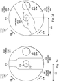
- FIGS. 3a-3f illustrate aspects of the filter wheel 300, including various filtering positions.
- the filter wheel 300 can include the unfiltered area 302 configured to permit full transmission of the light beam 210, the first filtered area 304 configured to limit the transmission of a first range of wavelengths, and the second filtered area 306 configured to limit a transmission of the second range of wavelengths. Wavelengths of the light beam 210 outside of the first and second filtered wavelength ranges can be allowed to pass through the first and second filtered areas 304, 306, respectively, without being impeded.
- the first and second ranges of filtered wavelengths can be selected at least partially based on the light source 110 (e.g., the beam composition) of the ophthalmic surgical system 100 and/or wavelengths known to cause damage to the eye, such as blue light wavelengths.
- the first and/or second range of wavelengths can include wavelengths between about 350 nm and about 520 nm, between about 350 nm and about 515 nm, between about 380 nm and about 480 nm, or other suitable range.
- the first range of wavelengths can be between approximately 380 nm and approximately 475 nm
- the second range of wavelengths can be between approximately 380 nm and approximately 515 nm.
- the first and second filtered areas 304, 306 can be bandpass filters.
- the first filtered area 304 can be configured to permit wavelengths of the light beam 210 between approximately 475 nm and approximately 650 nm to pass through the filter wheel 300 without being impeded and to limit the transmission of wavelengths outside of that range.
- the second filtered area 306 can be configured to permit wavelengths of the light beam 210 between approximately 515 nm and approximately 650 nm to pass through the filter wheel 300 without being impeded and to limit the transmission of wavelengths outside of that range.
- the filter wheel 300 can have a circular or disc profile, as shown in FIGS. 2a-3f .
- the size of the filter wheel 300 (e.g., height, width, diameter, thickness, etc.), including the areas used to define the unfiltered area 302, the first filtered area 304, and the second filtered area 306, can be selected based on the expected diameter range(s) of the light beam 210.
- the filter wheel 300 can have a radius 308 between about 10 mm and about 50 mm, between about 12 mm and 50 mm, or between about 12 mm and about 45 mm, including values such as 12 mm, 13 mm, 14 mm, 15 mm, 16 mm, 17 mm, 18 mm, 19 mm, 20 mm, or other suitable value.
- the filter wheel 300 can also have other configurations, including symmetric, non-symmetric, geometric, and/or non-geometric profiles of various sizes.
- the unfiltered area 302 can be positioned adjacent to the first filtered area 304 and/or the second filtered area 306 to allow the light beam 210 to pass at least partially through one or more of the unfiltered area 302, the first filtered area 304, and the second filtered area 306, as discussed below.
- the unfiltered area 302, the first filtered area 304, and/or the second filtered area 306 can be variously sized and shaped such that a complete diameter of the light beam 210 or any portion thereof can pass therethrough.
- the unfiltered area 302, the first filtered area 304, and/or the second filtered area 306 can be positioned at any location on the filter wheel 300.
- the filter wheel 300 can include any number of filtered areas and any number of unfiltered areas arranged in a suitable manner to facilitate selective filtering of any number of wavelength ranges.
- the filter wheel 300 can be made of or include glass, quartz glass, meteoritic glass, germanium, fluorite, plastic, high index plastic, Trivex, acrylic, polycarbonate, or other suitable material.
- the entirety of the filter wheel 300 can be made of the same material(s) or different portions of the filter wheel (e.g., the unfiltered area 302, the first filtered area 304, and the second filtered area 306) can be made of different material(s).
- Each of the filtered areas of the filter wheel 300 can be an absorptive or dichroic filter.
- the filter wheel 300 can include one or more optical coatings and/or embedded compounds to define the filtered areas.
- the optical coating(s) and/or embedded compound(s) can be selected and/or applied in a manner to achieve filtering of the desired wavelengths.
- the optical coating(s) and/or embedded compound(s) can include plastic, metal oxide, zinc sulfide, zinc selenide, sodium aluminum fluoride, natural and/or synthetic dye, organic and/or inorganic dye, colloidal dye, a rare earth transition element, or other suitable material(s).
- the filter wheel can include an anti-reflective coating and/or a protective coating.
- the unfiltered area 302 can include an anti-reflective coating. With the anti-reflective coating, the reflectance of the unfiltered area 302 can be less than or equal to approximately 1.0% of incident light.
- Performing an ophthalmic surgical procedure can include guiding the light beam 210 through the filter wheel 300 to the intraocular illumination device 120.
- the filter wheel 300 can be selectively moved to cause the light beam 210 to pass entirely or partially through the unfiltered area 302, the first filtered area 304, and/or the second filtered area 306 during operation of the ophthalmic surgical system 100.
- the light beam 210 can be directed at least partially through the unfiltered area 302 when phototoxicity and the Aphakic Hazard metric present less of a concern, such as during surgery on the periphery of the retina.
- the light beam 210 can be directed at least partially through the first filtered area 304 when phototoxicity and the Aphakic Hazard metric present more of a concern, such as during surgery near the macula.
- the light beam 210 can be directed at least partially through the second filtered area 306 when phototoxicity and the Aphakic Hazard metric present an even greater concern, such as during extended surgery near the macula.
- the transmission of light within the first and/or second wavelength ranges can be limited or attenuated by the first and/or second filtered areas 304, 306 between 0% and 100%.
- 0% attenuation can occur when the complete diameter of the light beam 210 passes through unfiltered area 302.
- 100% attenuation within first and second wavelength range can occur when the complete diameter of the light beam 210 passes entirely through the first filtered area 304 or the second filtered area 306, respectively.
- Attenuation between 0% and 100% can occur when portions of the light beam simultaneously pass through the unfiltered area 302 and at least one of the first and/or second filtered areas 304, 306.
- the filter wheel 300 can be moved such that the first and/or second ranges of wavelengths of the light beam 210 can be limited in increments of approximately 1%, 5%, 10%, 20%, 25%, 50%, or other suitable value.
- the filter wheel 300 can be positioned such that a certain percentage of the cross-sectional area of the light beam 210 passes through the filtered area(s) of the filter wheel to achieve a desired amount of filtering.
- the actuator 220 can be configured to move the filter wheel 300 incrementally to achieve the desired amount of filtering.
- the actuator 220 can be configured to move the filter wheel 300 in increments such that between about 0% and 100%, between about 0% and 75%, and/or between about 0% and 50% of the cross-sectional area of the light beam 210 can be introduced/removed from the beam path 102 upon each incrementally actuation.
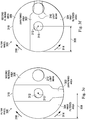
- FIGS. 3a-3f illustrate various positions of the filter wheel 300 associated with different amounts of desired filtering.
- the filter wheel 300 can be moved between the various positions shown in FIGS. 3a-3f by rotating about an axis of rotation 310.
- the filter wheel 300 can be moved in a clockwise direction 316 and/or a counterclockwise direction 314 about the axis of rotation 310 between the various positions.
- FIG. 3a illustrates a position of the filter wheel 300 where the entire diameter of the light beam 210 passes through the unfiltered area 302.
- FIG. 3b illustrates a position of the filter wheel 300 where the light beam 210 passes partially through the unfiltered area 302 and partially through the first filtered area 304 such that the transmission of the first range of wavelengths can be partially limited.
- FIG. 3c illustrates a position of the filter wheel 300 where the entire diameter of the light beam 210 passes through the first filtered area 304 such that the transmission of the first range of wavelengths can be completely limited by the first filtered area 304.
- FIG. 3a illustrates a position of the filter wheel 300 where the entire diameter of the light beam 210 passes through the unfiltered area 302.
- FIG. 3b illustrates a position of the filter wheel 300 where the light beam 210 passes partially through the unfiltered area 302 and partially through the first filtered area 304 such that the transmission of the first range of wavelengths can be partially limited.
- FIG. 3c illustrates a position of the filter wheel
- FIG. 3d illustrates a position of the filter wheel 300 where the light beam 210 passes partially through the unfiltered area 302 and partially through the second filtered area 306 such that the transmission of the second range of wavelengths can be partially limited.
- FIG. 3e illustrates a position of the filter wheel 300 where the entire diameter of the light beam 210 passes through the second filtered area 306 such that the transmission of the second range of wavelengths can be completely limited by the second filtered area 306.
- FIG. 3f illustrates a position of the filter wheel 300 where the light beam 210 passes partially through the unfiltered area 302, partially through the first filtered area 304, and partially through the second filtered area 306 such that the transmission of the first and second ranges of wavelengths can be partially limited.
- the filter wheel 300 can be automatically rotated to position a desired amount of the unfiltered area 302, the first filtered area 304, and/or the second filtered area 306 in the path of the light beam 210 based on one or more conditions associated with the ophthalmic surgical system 100 and/or a surgical procedure.
- the filter wheel 300 can be moved (e.g., the computing device 130 can provide a control signal to the actuator 220) based on a beam location, a beam composition, an exposure time, and/or a limited visibility condition.
- the beam location can indicate the target location of the light in the surgical field (e.g., the macula, the periphery of the retina, etc.).
- the filter wheel 300 can be moved such that the light beam 210 passes at least partially through the first or second filtered area 304, 306.
- the beam composition can describe an amount of blue light included in the light being transmitted to the surgical field. If the light being transmitted includes a potentially harmful amount of blue light, the filter wheel 300 can be moved such that the light beam 210 passes at least partially through the first or second filtered area 304, 306.
- the exposure time can indicate how long the light has been transmitted to the surgical field. If the surgical procedure lasts for an extended duration such that continued transmission of blue light could be harmful, the filter wheel 300 can be moved such that the light beam 210 passes at least partially through the first or second filtered area 304, 306.
- a limited visibility condition can describe one or more physiological characteristics of a patient that limit a surgeon's ability to see relevant anatomy during the surgical procedure. For example, cataracts, vitreous hemorrhage, and/or high pigmentation can cause a limited visibility condition.
- the filter wheel 300 can be moved such that the light beam 210 passes at least partially through the unfiltered area 302.
- Embodiments as described herein can relate to devices, systems, and methods that facilitate blue light filtering during ophthalmic surgical procedures.
- the examples provided above are exemplary only and are not intended to be limiting.
- One skilled in the art may readily devise other systems consistent with the disclosed embodiments which are intended to be within the scope of this disclosure. As such, the application is limited only by the following claims.
Landscapes
- Health & Medical Sciences (AREA)
- Life Sciences & Earth Sciences (AREA)
- Physics & Mathematics (AREA)
- Surgery (AREA)
- General Health & Medical Sciences (AREA)
- Public Health (AREA)
- Animal Behavior & Ethology (AREA)
- Veterinary Medicine (AREA)
- Engineering & Computer Science (AREA)
- Biomedical Technology (AREA)
- Heart & Thoracic Surgery (AREA)
- Ophthalmology & Optometry (AREA)
- Nuclear Medicine, Radiotherapy & Molecular Imaging (AREA)
- Medical Informatics (AREA)
- Molecular Biology (AREA)
- Optics & Photonics (AREA)
- General Physics & Mathematics (AREA)
- Pathology (AREA)
- Oral & Maxillofacial Surgery (AREA)
- Vascular Medicine (AREA)
- Biophysics (AREA)
- Astronomy & Astrophysics (AREA)
- Spectroscopy & Molecular Physics (AREA)
- Prostheses (AREA)
- Optical Filters (AREA)
Claims (10)
- Système chirurgical ophtalmique (100), comprenant :une source de lumière (110) configurée pour générer un faisceau lumineux (210) ;une roue filtrante (300) disposée entre la source de lumière et un dispositif d'éclairage intraoculaire (120), la roue filtrante comprenantune zone transparente (302) qui permet que sensiblement toutes les longueurs d'onde la traversent librement ;une première zone filtrée (304) configurée pour limiter la transmission d'une première plage de longueurs d'onde du faisceau lumineux vers le dispositif d'éclairage intraoculaire ; etune seconde zone filtrée (306) configurée pour limiter la transmission d'une seconde plage de longueurs d'onde du faisceau lumineux vers le dispositif d'éclairage intraoculaire ; etun actionneur (220) configuré pour déplacer sélectivement la roue filtrante pour amener le faisceau lumineux à traverser au moins l'une parmi la zone transparente, la première zone filtrée et la seconde zone filtrée de la roue filtrante ; etcaractérisé par un dispositif informatique (130) en communication avec l'actionneur (220) et configuré pour :surveiller les plages de longueurs d'onde de la lumière qui a été transmise vers un champ chirurgical par le dispositif d'éclairage intraoculaire (120) ; etfaire tourner automatiquement la roue filtrante sur la base d'une quantité de lumière bleue incluse dans la lumière en cours de transmission vers le champ chirurgical de sorte que le faisceau lumineux traverse au moins une parmi la zone transparente (302), la première zone filtrée (304) et la seconde zone filtrée (306).
- Système chirurgical ophtalmique selon la revendication 1, dans lequel :
la première zone filtrée (304) est positionnée de manière adjacente à la zone transparente (302). - Système chirurgical ophtalmique selon la revendication 2, dans lequel :
la seconde zone filtrée (306) est positionnée de manière adjacente à la zone transparente (302). - Système chirurgical ophtalmique selon la revendication 3, dans lequel :
la zone transparente (302) s'étend entre la première zone filtrée (304) et la seconde zone filtrée (306). - Système chirurgical ophtalmique selon la revendication 1, dans lequel :
au moins une des première et seconde plages de longueurs d'onde est sélectionnée pour limiter la transmission de lumière bleue vers le dispositif d'éclairage intraoculaire (120). - Système chirurgical ophtalmique selon la revendication 5, dans lequel :
la première plage de longueurs d'onde comprend des longueurs d'onde entre approximativement 380 nm et approximativement 475 nm. - Système chirurgical ophtalmique selon la revendication 6, dans lequel :
la seconde plage de longueurs d'onde comprend des longueurs d'onde entre approximativement 380 nm et approximativement 515 nm. - Système chirurgical ophtalmique selon la revendication 1, dans lequel :
l'actionneur (220) est configuré pour déplacer par incréments la roue filtrante (300). - Système chirurgical ophtalmique selon la revendication 1, dans lequel :
le dispositif informatique (130) en communication avec l'actionneur (220) est en outre configuré pour fournir un signal de commande à l'actionneur pour déplacer sélectivement la roue filtrante (300) vers une position à laquelle le faisceau lumineux traverse simultanément une partie de la zone transparente (302) et une partie d'au moins l'une parmi la première zone filtrée (304) et la seconde zone filtrée (306). - Système chirurgical ophtalmique selon la revendication 9, dans lequel :
le dispositif informatique (130) est configuré pour fournir le signal de commande à l'actionneur (220) sur la base d'au moins l'un parmi un emplacement de faisceau, une composition de faisceau, un temps d'exposition et une condition de visibilité limitée.
Applications Claiming Priority (2)
| Application Number | Priority Date | Filing Date | Title |
|---|---|---|---|
| US14/309,653 US9386918B2 (en) | 2014-06-19 | 2014-06-19 | Ophthalmic surgical system with blue light filtering |
| PCT/US2015/030584 WO2015195229A1 (fr) | 2014-06-19 | 2015-05-13 | Système chirurgical ophtalmique ayant une filtration de lumière bleue |
Publications (3)
| Publication Number | Publication Date |
|---|---|
| EP3128896A1 EP3128896A1 (fr) | 2017-02-15 |
| EP3128896A4 EP3128896A4 (fr) | 2017-06-21 |
| EP3128896B1 true EP3128896B1 (fr) | 2021-02-17 |
Family
ID=54868539
Family Applications (1)
| Application Number | Title | Priority Date | Filing Date |
|---|---|---|---|
| EP15810080.0A Active EP3128896B1 (fr) | 2014-06-19 | 2015-05-13 | Système chirurgical ophtalmique ayant une filtration de lumière bleue |
Country Status (7)
| Country | Link |
|---|---|
| US (2) | US9386918B2 (fr) |
| EP (1) | EP3128896B1 (fr) |
| JP (1) | JP6619365B2 (fr) |
| CN (1) | CN106455971B (fr) |
| AU (1) | AU2015277787B2 (fr) |
| CA (1) | CA2949218C (fr) |
| WO (1) | WO2015195229A1 (fr) |
Families Citing this family (6)
| Publication number | Priority date | Publication date | Assignee | Title |
|---|---|---|---|---|
| US9386918B2 (en) * | 2014-06-19 | 2016-07-12 | Novartis Ag | Ophthalmic surgical system with blue light filtering |
| US10400967B2 (en) | 2016-06-13 | 2019-09-03 | Novartis Ag | Ophthalmic illumination system with controlled chromaticity |
| WO2018092006A2 (fr) | 2016-11-17 | 2018-05-24 | Novartis Ag | Pédale ergonomique triaxiale |
| CN110022803B (zh) | 2016-11-30 | 2021-06-11 | 爱尔康公司 | 用于在眼科手术期间监测光毒性的系统和方法 |
| CN111290205B (zh) * | 2018-12-07 | 2022-03-04 | 深圳光峰科技股份有限公司 | 发光装置、显示设备及发光装置的控制方法 |
| CN112618155A (zh) * | 2020-12-17 | 2021-04-09 | 上海市普陀区中心医院 | 一种用于眼科激光手术的滤光防护结构 |
Family Cites Families (13)
| Publication number | Priority date | Publication date | Assignee | Title |
|---|---|---|---|---|
| US6309070B1 (en) * | 2000-09-06 | 2001-10-30 | Medibell Medical Vision Technologies, Ltd. | Integrated ophthalmic illumination method and system |
| JP3929735B2 (ja) * | 2001-10-03 | 2007-06-13 | 独立行政法人科学技術振興機構 | 眼内照明用プローブおよび眼科手術用装置 |
| US20060268231A1 (en) * | 2003-07-03 | 2006-11-30 | Medibell Medicall Vision Technologies, Ltd. | Illumination method and system for obtaining color images by transcleral ophthalmic illumination |
| US7654716B1 (en) * | 2006-11-10 | 2010-02-02 | Doheny Eye Institute | Enhanced visualization illumination system |
| JP5031405B2 (ja) * | 2007-03-02 | 2012-09-19 | キヤノン株式会社 | 眼科撮影装置、眼科撮影装置の制御方法およびプログラム |
| US7499624B2 (en) * | 2007-03-16 | 2009-03-03 | Alcon, Inc. | Ophthalmic Endoilluminator with Variable-Wedge Rotating-Disk Beam Attenuator |
| US20080246919A1 (en) * | 2007-04-09 | 2008-10-09 | Ron Smith | Ophthalmic Endoilluminator with Hybrid Lens |
| US20090240138A1 (en) * | 2008-03-18 | 2009-09-24 | Steven Yi | Diffuse Optical Tomography System and Method of Use |
| US20100157247A1 (en) * | 2008-12-19 | 2010-06-24 | Simon Roderick Grover | Ophthalmic illumination filter selection mechanism |
| DE102009017710B4 (de) * | 2009-04-14 | 2019-10-31 | Carl Zeiss Meditec Ag | Optisches Beobachtungsgerät und Verfahren zum Gewährleisten einer gleich bleibenden Beleuchtungsintensität bei einem Wechsel der Farbtemperatur der Beleuchtung |
| US20120083772A1 (en) * | 2010-09-30 | 2012-04-05 | Curveright Llc | Corneal treatment system and method |
| TWI464452B (zh) * | 2012-08-27 | 2014-12-11 | Delta Electronics Inc | 顯示器及其顯示方法 |
| US9386918B2 (en) * | 2014-06-19 | 2016-07-12 | Novartis Ag | Ophthalmic surgical system with blue light filtering |
-
2014
- 2014-06-19 US US14/309,653 patent/US9386918B2/en active Active
-
2015
- 2015-05-13 WO PCT/US2015/030584 patent/WO2015195229A1/fr active Application Filing
- 2015-05-13 CA CA2949218A patent/CA2949218C/fr active Active
- 2015-05-13 CN CN201580032310.4A patent/CN106455971B/zh active Active
- 2015-05-13 AU AU2015277787A patent/AU2015277787B2/en active Active
- 2015-05-13 JP JP2016573120A patent/JP6619365B2/ja active Active
- 2015-05-13 EP EP15810080.0A patent/EP3128896B1/fr active Active
-
2016
- 2016-06-02 US US15/171,688 patent/US9849029B2/en active Active
Non-Patent Citations (1)
| Title |
|---|
| None * |
Also Published As
| Publication number | Publication date |
|---|---|
| US20150366446A1 (en) | 2015-12-24 |
| EP3128896A1 (fr) | 2017-02-15 |
| CN106455971B (zh) | 2018-09-25 |
| JP6619365B2 (ja) | 2019-12-11 |
| AU2015277787A1 (en) | 2016-12-01 |
| US9386918B2 (en) | 2016-07-12 |
| CA2949218A1 (fr) | 2015-12-23 |
| US20160278978A1 (en) | 2016-09-29 |
| WO2015195229A1 (fr) | 2015-12-23 |
| CA2949218C (fr) | 2023-05-09 |
| US9849029B2 (en) | 2017-12-26 |
| EP3128896A4 (fr) | 2017-06-21 |
| JP2017518124A (ja) | 2017-07-06 |
| AU2015277787B2 (en) | 2019-08-01 |
| CN106455971A (zh) | 2017-02-22 |
Similar Documents
| Publication | Publication Date | Title |
|---|---|---|
| US9849029B2 (en) | Ophthalmic surgical system with moveable light filter | |
| US20210393438A1 (en) | Device and method for laser assisted deep sclerectomy | |
| JP2018524028A (ja) | 周縁照明器具 | |
| JP5513134B2 (ja) | 可変光学くさび回転ディスク・ビーム・アッテネータを備えた眼科用内視鏡照明機器 | |
| EP2120679B1 (fr) | Attenuateur de faisceau a disque rotatif a prisme variable pour endo-illuminateur ophtalmique | |
| WO2005096766A3 (fr) | Methode et appareil pour le traitement de la melanose oculaire | |
| JP2008181128A (ja) | 光から所望しない波長を取除く装置と方法 | |
| JP4225734B2 (ja) | 照明の強度を部分的に低減する装置を有する光学的観察装置 | |
| US20170014269A1 (en) | Surgical instrument | |
| DE102012014769A1 (de) | Fortsetzung von unterbrochenen augenchirurgischen Schnitten | |
| US10188481B2 (en) | Beam guide for ophthalmic surgical illumination | |
| JP5722060B2 (ja) | 眼内観察用顕微鏡およびフィルタユニット | |
| US20230346600A1 (en) | Hybrid 2-port vitrectomy and combined treatment and infusion probe | |
| CN206557465U (zh) | 一种滤片切换机构及手术显微镜 | |
| JP2004081699A (ja) | レーザ用保護ゴーグル及びこれを備えるレーザ治療装置 |
Legal Events
| Date | Code | Title | Description |
|---|---|---|---|
| STAA | Information on the status of an ep patent application or granted ep patent |
Free format text: STATUS: THE INTERNATIONAL PUBLICATION HAS BEEN MADE |
|
| PUAI | Public reference made under article 153(3) epc to a published international application that has entered the european phase |
Free format text: ORIGINAL CODE: 0009012 |
|
| STAA | Information on the status of an ep patent application or granted ep patent |
Free format text: STATUS: REQUEST FOR EXAMINATION WAS MADE |
|
| 17P | Request for examination filed |
Effective date: 20161111 |
|
| AK | Designated contracting states |
Kind code of ref document: A1 Designated state(s): AL AT BE BG CH CY CZ DE DK EE ES FI FR GB GR HR HU IE IS IT LI LT LU LV MC MK MT NL NO PL PT RO RS SE SI SK SM TR |
|
| AX | Request for extension of the european patent |
Extension state: BA ME |
|
| A4 | Supplementary search report drawn up and despatched |
Effective date: 20170524 |
|
| RIC1 | Information provided on ipc code assigned before grant |
Ipc: A61B 90/00 20160101ALI20170518BHEP Ipc: A61F 9/007 20060101ALI20170518BHEP Ipc: A61B 3/00 20060101ALI20170518BHEP Ipc: G02B 5/20 20060101ALI20170518BHEP Ipc: A61B 90/30 20160101ALI20170518BHEP Ipc: A61B 3/10 20060101AFI20170518BHEP Ipc: G02B 26/00 20060101ALI20170518BHEP |
|
| DAV | Request for validation of the european patent (deleted) | ||
| DAX | Request for extension of the european patent (deleted) | ||
| STAA | Information on the status of an ep patent application or granted ep patent |
Free format text: STATUS: EXAMINATION IS IN PROGRESS |
|
| 17Q | First examination report despatched |
Effective date: 20190327 |
|
| RAP1 | Party data changed (applicant data changed or rights of an application transferred) |
Owner name: ALCON INC. |
|
| GRAP | Despatch of communication of intention to grant a patent |
Free format text: ORIGINAL CODE: EPIDOSNIGR1 |
|
| STAA | Information on the status of an ep patent application or granted ep patent |
Free format text: STATUS: GRANT OF PATENT IS INTENDED |
|
| INTG | Intention to grant announced |
Effective date: 20200401 |
|
| GRAJ | Information related to disapproval of communication of intention to grant by the applicant or resumption of examination proceedings by the epo deleted |
Free format text: ORIGINAL CODE: EPIDOSDIGR1 |
|
| STAA | Information on the status of an ep patent application or granted ep patent |
Free format text: STATUS: EXAMINATION IS IN PROGRESS |
|
| INTC | Intention to grant announced (deleted) | ||
| GRAS | Grant fee paid |
Free format text: ORIGINAL CODE: EPIDOSNIGR3 |
|
| STAA | Information on the status of an ep patent application or granted ep patent |
Free format text: STATUS: GRANT OF PATENT IS INTENDED |
|
| GRAP | Despatch of communication of intention to grant a patent |
Free format text: ORIGINAL CODE: EPIDOSNIGR1 |
|
| INTG | Intention to grant announced |
Effective date: 20200921 |
|
| GRAA | (expected) grant |
Free format text: ORIGINAL CODE: 0009210 |
|
| STAA | Information on the status of an ep patent application or granted ep patent |
Free format text: STATUS: THE PATENT HAS BEEN GRANTED |
|
| AK | Designated contracting states |
Kind code of ref document: B1 Designated state(s): AL AT BE BG CH CY CZ DE DK EE ES FI FR GB GR HR HU IE IS IT LI LT LU LV MC MK MT NL NO PL PT RO RS SE SI SK SM TR |
|
| REG | Reference to a national code |
Ref country code: GB Ref legal event code: FG4D |
|
| REG | Reference to a national code |
Ref country code: CH Ref legal event code: EP |
|
| REG | Reference to a national code |
Ref country code: DE Ref legal event code: R096 Ref document number: 602015065703 Country of ref document: DE |
|
| REG | Reference to a national code |
Ref country code: AT Ref legal event code: REF Ref document number: 1360360 Country of ref document: AT Kind code of ref document: T Effective date: 20210315 |
|
| REG | Reference to a national code |
Ref country code: IE Ref legal event code: FG4D |
|
| REG | Reference to a national code |
Ref country code: LT Ref legal event code: MG9D |
|
| REG | Reference to a national code |
Ref country code: NL Ref legal event code: MP Effective date: 20210217 |
|
| PG25 | Lapsed in a contracting state [announced via postgrant information from national office to epo] |
Ref country code: LT Free format text: LAPSE BECAUSE OF FAILURE TO SUBMIT A TRANSLATION OF THE DESCRIPTION OR TO PAY THE FEE WITHIN THE PRESCRIBED TIME-LIMIT Effective date: 20210217 Ref country code: PT Free format text: LAPSE BECAUSE OF FAILURE TO SUBMIT A TRANSLATION OF THE DESCRIPTION OR TO PAY THE FEE WITHIN THE PRESCRIBED TIME-LIMIT Effective date: 20210617 Ref country code: NO Free format text: LAPSE BECAUSE OF FAILURE TO SUBMIT A TRANSLATION OF THE DESCRIPTION OR TO PAY THE FEE WITHIN THE PRESCRIBED TIME-LIMIT Effective date: 20210517 Ref country code: BG Free format text: LAPSE BECAUSE OF FAILURE TO SUBMIT A TRANSLATION OF THE DESCRIPTION OR TO PAY THE FEE WITHIN THE PRESCRIBED TIME-LIMIT Effective date: 20210517 Ref country code: HR Free format text: LAPSE BECAUSE OF FAILURE TO SUBMIT A TRANSLATION OF THE DESCRIPTION OR TO PAY THE FEE WITHIN THE PRESCRIBED TIME-LIMIT Effective date: 20210217 Ref country code: FI Free format text: LAPSE BECAUSE OF FAILURE TO SUBMIT A TRANSLATION OF THE DESCRIPTION OR TO PAY THE FEE WITHIN THE PRESCRIBED TIME-LIMIT Effective date: 20210217 Ref country code: GR Free format text: LAPSE BECAUSE OF FAILURE TO SUBMIT A TRANSLATION OF THE DESCRIPTION OR TO PAY THE FEE WITHIN THE PRESCRIBED TIME-LIMIT Effective date: 20210518 |
|
| REG | Reference to a national code |
Ref country code: AT Ref legal event code: MK05 Ref document number: 1360360 Country of ref document: AT Kind code of ref document: T Effective date: 20210217 |
|
| PG25 | Lapsed in a contracting state [announced via postgrant information from national office to epo] |
Ref country code: SE Free format text: LAPSE BECAUSE OF FAILURE TO SUBMIT A TRANSLATION OF THE DESCRIPTION OR TO PAY THE FEE WITHIN THE PRESCRIBED TIME-LIMIT Effective date: 20210217 Ref country code: PL Free format text: LAPSE BECAUSE OF FAILURE TO SUBMIT A TRANSLATION OF THE DESCRIPTION OR TO PAY THE FEE WITHIN THE PRESCRIBED TIME-LIMIT Effective date: 20210217 Ref country code: LV Free format text: LAPSE BECAUSE OF FAILURE TO SUBMIT A TRANSLATION OF THE DESCRIPTION OR TO PAY THE FEE WITHIN THE PRESCRIBED TIME-LIMIT Effective date: 20210217 Ref country code: NL Free format text: LAPSE BECAUSE OF FAILURE TO SUBMIT A TRANSLATION OF THE DESCRIPTION OR TO PAY THE FEE WITHIN THE PRESCRIBED TIME-LIMIT Effective date: 20210217 Ref country code: RS Free format text: LAPSE BECAUSE OF FAILURE TO SUBMIT A TRANSLATION OF THE DESCRIPTION OR TO PAY THE FEE WITHIN THE PRESCRIBED TIME-LIMIT Effective date: 20210217 |
|
| PG25 | Lapsed in a contracting state [announced via postgrant information from national office to epo] |
Ref country code: IS Free format text: LAPSE BECAUSE OF FAILURE TO SUBMIT A TRANSLATION OF THE DESCRIPTION OR TO PAY THE FEE WITHIN THE PRESCRIBED TIME-LIMIT Effective date: 20210617 |
|
| PG25 | Lapsed in a contracting state [announced via postgrant information from national office to epo] |
Ref country code: AT Free format text: LAPSE BECAUSE OF FAILURE TO SUBMIT A TRANSLATION OF THE DESCRIPTION OR TO PAY THE FEE WITHIN THE PRESCRIBED TIME-LIMIT Effective date: 20210217 Ref country code: SM Free format text: LAPSE BECAUSE OF FAILURE TO SUBMIT A TRANSLATION OF THE DESCRIPTION OR TO PAY THE FEE WITHIN THE PRESCRIBED TIME-LIMIT Effective date: 20210217 Ref country code: EE Free format text: LAPSE BECAUSE OF FAILURE TO SUBMIT A TRANSLATION OF THE DESCRIPTION OR TO PAY THE FEE WITHIN THE PRESCRIBED TIME-LIMIT Effective date: 20210217 Ref country code: CZ Free format text: LAPSE BECAUSE OF FAILURE TO SUBMIT A TRANSLATION OF THE DESCRIPTION OR TO PAY THE FEE WITHIN THE PRESCRIBED TIME-LIMIT Effective date: 20210217 |
|
| REG | Reference to a national code |
Ref country code: DE Ref legal event code: R097 Ref document number: 602015065703 Country of ref document: DE |
|
| PG25 | Lapsed in a contracting state [announced via postgrant information from national office to epo] |
Ref country code: RO Free format text: LAPSE BECAUSE OF FAILURE TO SUBMIT A TRANSLATION OF THE DESCRIPTION OR TO PAY THE FEE WITHIN THE PRESCRIBED TIME-LIMIT Effective date: 20210217 Ref country code: SK Free format text: LAPSE BECAUSE OF FAILURE TO SUBMIT A TRANSLATION OF THE DESCRIPTION OR TO PAY THE FEE WITHIN THE PRESCRIBED TIME-LIMIT Effective date: 20210217 Ref country code: ES Free format text: LAPSE BECAUSE OF FAILURE TO SUBMIT A TRANSLATION OF THE DESCRIPTION OR TO PAY THE FEE WITHIN THE PRESCRIBED TIME-LIMIT Effective date: 20210217 Ref country code: DK Free format text: LAPSE BECAUSE OF FAILURE TO SUBMIT A TRANSLATION OF THE DESCRIPTION OR TO PAY THE FEE WITHIN THE PRESCRIBED TIME-LIMIT Effective date: 20210217 |
|
| PLBE | No opposition filed within time limit |
Free format text: ORIGINAL CODE: 0009261 |
|
| STAA | Information on the status of an ep patent application or granted ep patent |
Free format text: STATUS: NO OPPOSITION FILED WITHIN TIME LIMIT |
|
| REG | Reference to a national code |
Ref country code: CH Ref legal event code: PL |
|
| 26N | No opposition filed |
Effective date: 20211118 |
|
| PG25 | Lapsed in a contracting state [announced via postgrant information from national office to epo] |
Ref country code: CH Free format text: LAPSE BECAUSE OF NON-PAYMENT OF DUE FEES Effective date: 20210531 Ref country code: AL Free format text: LAPSE BECAUSE OF FAILURE TO SUBMIT A TRANSLATION OF THE DESCRIPTION OR TO PAY THE FEE WITHIN THE PRESCRIBED TIME-LIMIT Effective date: 20210217 Ref country code: MC Free format text: LAPSE BECAUSE OF FAILURE TO SUBMIT A TRANSLATION OF THE DESCRIPTION OR TO PAY THE FEE WITHIN THE PRESCRIBED TIME-LIMIT Effective date: 20210217 Ref country code: LU Free format text: LAPSE BECAUSE OF NON-PAYMENT OF DUE FEES Effective date: 20210513 Ref country code: LI Free format text: LAPSE BECAUSE OF NON-PAYMENT OF DUE FEES Effective date: 20210531 |
|
| REG | Reference to a national code |
Ref country code: BE Ref legal event code: MM Effective date: 20210531 |
|
| PG25 | Lapsed in a contracting state [announced via postgrant information from national office to epo] |
Ref country code: SI Free format text: LAPSE BECAUSE OF FAILURE TO SUBMIT A TRANSLATION OF THE DESCRIPTION OR TO PAY THE FEE WITHIN THE PRESCRIBED TIME-LIMIT Effective date: 20210217 |
|
| PG25 | Lapsed in a contracting state [announced via postgrant information from national office to epo] |
Ref country code: IT Free format text: LAPSE BECAUSE OF FAILURE TO SUBMIT A TRANSLATION OF THE DESCRIPTION OR TO PAY THE FEE WITHIN THE PRESCRIBED TIME-LIMIT Effective date: 20210217 Ref country code: IE Free format text: LAPSE BECAUSE OF NON-PAYMENT OF DUE FEES Effective date: 20210513 |
|
| PG25 | Lapsed in a contracting state [announced via postgrant information from national office to epo] |
Ref country code: IS Free format text: LAPSE BECAUSE OF FAILURE TO SUBMIT A TRANSLATION OF THE DESCRIPTION OR TO PAY THE FEE WITHIN THE PRESCRIBED TIME-LIMIT Effective date: 20210617 |
|
| PG25 | Lapsed in a contracting state [announced via postgrant information from national office to epo] |
Ref country code: BE Free format text: LAPSE BECAUSE OF NON-PAYMENT OF DUE FEES Effective date: 20210531 |
|
| PG25 | Lapsed in a contracting state [announced via postgrant information from national office to epo] |
Ref country code: HU Free format text: LAPSE BECAUSE OF FAILURE TO SUBMIT A TRANSLATION OF THE DESCRIPTION OR TO PAY THE FEE WITHIN THE PRESCRIBED TIME-LIMIT; INVALID AB INITIO Effective date: 20150513 |
|
| P01 | Opt-out of the competence of the unified patent court (upc) registered |
Effective date: 20230504 |
|
| PG25 | Lapsed in a contracting state [announced via postgrant information from national office to epo] |
Ref country code: CY Free format text: LAPSE BECAUSE OF FAILURE TO SUBMIT A TRANSLATION OF THE DESCRIPTION OR TO PAY THE FEE WITHIN THE PRESCRIBED TIME-LIMIT Effective date: 20210217 |
|
| PGFP | Annual fee paid to national office [announced via postgrant information from national office to epo] |
Ref country code: FR Payment date: 20230421 Year of fee payment: 9 Ref country code: DE Payment date: 20230418 Year of fee payment: 9 |
|
| PGFP | Annual fee paid to national office [announced via postgrant information from national office to epo] |
Ref country code: GB Payment date: 20230420 Year of fee payment: 9 |
|
| PG25 | Lapsed in a contracting state [announced via postgrant information from national office to epo] |
Ref country code: MK Free format text: LAPSE BECAUSE OF FAILURE TO SUBMIT A TRANSLATION OF THE DESCRIPTION OR TO PAY THE FEE WITHIN THE PRESCRIBED TIME-LIMIT Effective date: 20210217 |