EP3128359A1 - Display device for a portable object such as a timepiece - Google Patents
Display device for a portable object such as a timepiece Download PDFInfo
- Publication number
- EP3128359A1 EP3128359A1 EP15179856.8A EP15179856A EP3128359A1 EP 3128359 A1 EP3128359 A1 EP 3128359A1 EP 15179856 A EP15179856 A EP 15179856A EP 3128359 A1 EP3128359 A1 EP 3128359A1
- Authority
- EP
- European Patent Office
- Prior art keywords
- pattern
- strips
- lenticular
- rectilinear
- transparent
- Prior art date
- Legal status (The legal status is an assumption and is not a legal conclusion. Google has not performed a legal analysis and makes no representation as to the accuracy of the status listed.)
- Withdrawn
Links
Images


Classifications
-
- G—PHYSICS
- G02—OPTICS
- G02B—OPTICAL ELEMENTS, SYSTEMS OR APPARATUS
- G02B27/00—Optical systems or apparatus not provided for by any of the groups G02B1/00 - G02B26/00, G02B30/00
- G02B27/02—Viewing or reading apparatus
- G02B27/06—Viewing or reading apparatus with moving picture effect
-
- G—PHYSICS
- G04—HOROLOGY
- G04B—MECHANICALLY-DRIVEN CLOCKS OR WATCHES; MECHANICAL PARTS OF CLOCKS OR WATCHES IN GENERAL; TIME PIECES USING THE POSITION OF THE SUN, MOON OR STARS
- G04B45/00—Time pieces of which the indicating means or cases provoke special effects, e.g. aesthetic effects
- G04B45/0015—Light-, colour-, line- or spot-effects caused by or on stationary parts
-
- G—PHYSICS
- G09—EDUCATION; CRYPTOGRAPHY; DISPLAY; ADVERTISING; SEALS
- G09F—DISPLAYING; ADVERTISING; SIGNS; LABELS OR NAME-PLATES; SEALS
- G09F19/00—Advertising or display means not otherwise provided for
- G09F19/12—Advertising or display means not otherwise provided for using special optical effects
- G09F19/14—Advertising or display means not otherwise provided for using special optical effects displaying different signs depending upon the view-point of the observer
-
- G—PHYSICS
- G02—OPTICS
- G02B—OPTICAL ELEMENTS, SYSTEMS OR APPARATUS
- G02B3/00—Simple or compound lenses
- G02B3/0006—Arrays
- G02B3/0037—Arrays characterized by the distribution or form of lenses
- G02B3/005—Arrays characterized by the distribution or form of lenses arranged along a single direction only, e.g. lenticular sheets
Definitions
- the present invention relates to a display device for a portable object such as a timepiece.
- the present invention particularly relates to a display device for a portable object having a changing appearance depending on the angle at which the observer looks at this display device.
- lenticular lens array designates a network formed of a layer of juxtaposed cylindrical lenses which extend parallel to each other. Most often, these lenses called “cylindrical” are not literally cylindrical. It will be understood that the term “cylindrical lens” is to be used here in a broad sense and refers to any lens having an optical axis O-O and having, in cross section, an invariant profile over its entire length.
- lenticular networks are already known as such. Lenticular arrays suitable for carrying out the invention are even commercially available from several companies. These networks are generally in the form of sheets of relatively large size that can be cut to the desired size. These lenticular leaves are made of a transparent material and stable. They normally have a smooth back surface that allows to fix the sheet on a substrate.
- a known use of lenticular networks consists in arranging a representation of two different patterns under a lenticular lens array. Depending on the angle at which the observer looks at the patterns, he will first perceive one of the patterns, then the other pattern different from the first one, which allows to create a changing dynamic display.
- the representation of the two patterns can be carried by a substrate and be covered by the lenticular lens array.
- the lenticular network may itself constitute the plane that carries the patterns to be displayed.
- the patterns are applied directly to the smooth surface of the lenticular sheet, for example by printing.
- the cylindrical lenses of the lenticular arrays have a focal length such that the focal plane of the lenses coincides with the plane in which the patterns to be displayed extend.
- the patterns to be displayed are usually fragmented into straight strips that are nested so that there is always a straight strip of the second pattern between two straight strips of the first pattern. It is also noted that the rectilinear bands of the first pattern, just like the rectilinear strips of the second pattern, follow each other with a pitch which is the same as that with which the cylindrical lenses of the lenticular network which covers the group of characters are repeated.
- lenticular lens arrays have heretofore always been used to display either two different patterns and thus create a changing dynamic display, or to display the same pattern but in two different sizes in order to create a zoom effect.
- the present invention aims to propose a new application of a lenticular lens array.
- the present invention relates to a device for displaying a pattern, this display device being intended to be integrated in a portable object and comprising a lenticular network through which the pattern is viewed and which is formed of a plurality of juxtaposed cylindrical lenses extending parallel to each other, the cylindrical lenses of the lenticular array having a focal length such that the focal plane of the cylindrical lenses coincides with the plane in which the pattern extends, the pattern being fragmented in rectilinear strips which extend parallel to each other, the rectilinear strips of the pattern being nested between transparent rectilinear strips, so that there is always a band of the pattern located between two transparent bands, the straight strips of the pattern, just like the transparent rectilinear strips, succeeding each other with a step that is the same as that with which the slow cylindrical cells of the lenticular network which covers the motive succeed each other.
- cylindrical is to be taken in the broad sense, the expression “cylindrical lens” here designating any lens having an optical axis and having, in cross section, a constant profile over its entire length.
- the "orientation" of a cylindrical lens corresponds to the orientation of the optical axis of this lens.
- the present invention provides a pattern display device in which the pattern, covered by a lenticular array formed of a plurality of juxtaposed cylindrical lenses, is fragmented into rectilinear strips interleaved between transparent strips, the rectilinear bands of the pattern, just like the transparent rectilinear bands, succeeding each other with a step that is the same as the one with which the cylindrical lenses of the lenticular network which covers the pattern follow each other. It is thus understood that, according to the angle at which the observer looks at the lenticular network, the observer sees either the pattern on an enlarged scale, or what is behind the lenticular network because the lenticular network appears transparent.
- the lenticular network which covers the pattern has a smooth back surface which constitutes the plane in which the pattern is formed.
- the plane in which the pattern is formed is constituted by a portion of the surface of a transparent dial.
- the colored bands which form the pattern to be displayed are applied to a thin plastic sheet placed between a transparent substrate and the lenticular network.
- the colored bands which form the pattern to be displayed by any appropriate printing technique such as the digital printing still known under its name.
- Anglo-Saxon denomination Digital Printing The patterns to be displayed can be printed on a large plastic sheet which is then secured under a lenticular network sheet of the same size, the resulting assembly then being cut into the desired shape.
- the present invention proceeds from the general inventive idea of using a lenticular array formed of a plurality of cylindrical lenses juxtaposed not to display two distinct patterns alternately visible according to the angle at which the observer looks at the lenticular network, but to pass such a lenticular network from a state in which it displays a pattern to a state in which it appears transparent in the eyes of the observer and leaves visible what is placed behind him.
- the present invention will be described with reference to a circular colored dial particularly adapted to be housed in a box of a portable object such as a watch, a mobile phone or a measuring instrument. It will be understood, however, that the present invention is not limited to such an embodiment and that the dials formed by the lenticular lens arrays can deviate from a circular shape by being for example square or rectangular, while the patterns visible under the lenticular networks can be at the choice of numbers, letters, a logo, a decorative pattern or other. Similarly, it is also possible to display a pattern by means of a fixed or dynamic display, for example of the LCD type or the like.
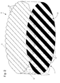
- the Figure 1A is a schematic top plan view of a circular shaped display pattern that is carried by a flat surface.
- the figure 1 B is a cross-sectional view of a lenticular array disposed above the pattern to be displayed in the Figure 1A .
- the pattern to be displayed is fragmented according to a plurality of rectilinear colored strips 2 extending in a plane 4 parallel to each other and interleaved between transparent rectilinear strips 6 devoid of any marking, so that there is always a colored band 2 of the pattern 1 to be displayed located between two transparent strips 6.
- the pattern 1 to be displayed is covered by a lenticular network 8 formed of a layer of juxtaposed cylindrical lenses 10 which extend parallel to each other.
- a lenticular network 8 formed of a layer of juxtaposed cylindrical lenses 10 which extend parallel to each other.
- the "cylindrical” lenses 10 are not literally cylindrical in shape. It will be understood that the term “cylindrical” is to be understood here in a broad sense, according to which the expression “cylindrical lens” refers to any lens having an optical axis OO and having, in cross section, an invariant profile over its entire length.
- lenticular networks are already known as such. They are generally in the form of leaves of relatively large size that can be cut to the desired size. These lenticular sheets are made of a transparent and stable material and normally have a smooth back surface 12 which makes it possible to fix the sheet on a substrate.
- the smooth reverse surface 12 of the lenticular array 8 may thus constitute the plane 4 which carries the pattern 1 to be displayed.
- the colored bands 2 which form the pattern 1 to be displayed are applied directly on the smooth verso surface 12 of the lenticular network 8, for example by printing.
- the lenticular network 8 alone forms the dial of the portable object .
- the rectilinear colored strips 2 are printed on a transparent substrate 14 and are covered by the lenticular network 8.
- the pattern 1 to be displayed is sandwiched between the lenticular network 8 and the transparent substrate 14, the assembly forming the dial intended to be integrated into the portable object.
- the rectilinear colored strips 2 which form the pattern 1 to be displayed are applied to a thin plastic sheet 16 placed between a transparent substrate 18 and the lenticular network 8.
- the cylindrical lenses 10 of the lenticular network 8 have a focal length such that the focal plane F of the cylindrical lenses 10 coincides with the plane 4 in which the pattern 1 extends.
- each of the cylindrical lenses 10 is split by a vertical plane P1 into first and second halves 10a and 10b of the same width L , the first half 10a of the cylindrical lens 10 covers at least one straight colored strip 2 of the pattern 1 to display, and the second half 10b of the cylindrical lens 10 covers at least one transparent strip 6.
- this is a simplified embodiment of the invention. Indeed, the progress made in recent years in the field of print resolution are such that it is now quite possible to have under the same cylindrical lens several rectilinear strips of the pattern to be displayed nested between transparent bands.
- the cylindrical lenses 10 of the lenticular array 8 have a focal length such that the focal plane F of the lenses coincides with the plane 4 in which the pattern 1 to be displayed extends. Under these conditions, each cylindrical lens 10 returns towards the eyes of an observer 20 the image of only one of the straight strips 2 or 6. This rectilinear strip is that which lies on either side of a plane P2 passing through the optical axis OO of the cylindrical lens 10 and the eyes of the observer 20.
- cylindrical lenses 10 of the lenticular array 8 are oriented in the same direction as the straight strips 2 , 6 that these cylindrical lenses 10 cover, this allows the observer to see the pattern 1, or to see through the lenticular network 8 by transparency effect.
- the observer 20 looks at the lenticular network 8 with the eyes placed on one side of the plane P2 , the observer 20 sees the image formed by the rectilinear colored strips 2.
- the eyes of the observer observer are placed on the other side of the plane P2 , he sees the rectilinear transparent strips 6.
- the lenticular network 8 returns to the observer 20 the image of the pattern 1 to be displayed, or the lenticular network 8 appears transparent to the viewer 20. Both aspects of the lenticular network are swung according to the angle of vision, creating a changing dynamic aspect.
- rectilinear strips 2 and 6 which are very thin.
- a 40 LPI lenticular array 40 cylindrical lenses per inch
- the width of the cylindrical lenses of such a network is about 2/3 of a millimeter.
- the width of the straight strips can be about 1/3 of a millimeter.
- FIGS. 4A and 4B are schematic views from above of the display device according to the invention in the case where the pattern 1 to be displayed is formed of a succession of rectilinear colored strips 2 extending parallel to each other and nested between rectilinear transparent strips 6.
- the dial formed by the lenticular network 8 and the transparent substrate 14 on which the rectilinear colored strips 2 are printed is housed in a wristwatch box 22 which comprises 24 hour and 26 minute hands driven by a movement
- the dial appears colored.
- the dial appears transparent to him and he can see the watch movement 28 through the dial.
- FIGS. 5A and 5B are schematic views from above of the display device according to the invention in the case where the pattern corresponds to hour markers forming the 30 hour turn of a timepiece. Under a first viewing angle, the observer sees the hour markers of the hour turn 30 in addition to the watch movement 28. Under a second viewing angle, the dial is transparent and the observer only sees the movement of the watch. watchmaking 28 placed behind it.
- the figure 6 is a schematic view of the method of manufacturing the display device according to the invention when the patterns 1 to be displayed are printed on a large plastic sheet 16 which is then secured in a lenticular network sheet 8 of the same dimensions, the resulting assembly being then cut into the desired shape.
Abstract
Dispositif d'affichage d'un motif (1), ce dispositif d'affichage étant destiné à être intégré dans un objet portable et comprenant un réseau lenticulaire (8) au travers duquel est vu le motif (1) et qui est formé d'une pluralité de lentilles cylindriques (10) juxtaposées s'étendant parallèlement les unes aux autres, les lentilles cylindriques (10) du réseau lenticulaire (8) ayant une distance focale (F) telle que le plan focal des lentilles cylindriques (10) est confondu avec le plan (4) dans lequel s'étend le motif (1), le motif (1) étant fragmenté en bandes rectilignes (2) qui s'étendent parallèlement les unes par rapport aux autres, les bandes rectilignes (2) du motif (1) étant imbriquées entre des bandes rectilignes transparentes (6), de façon qu'il y ait toujours une bande rectiligne (2) du motif (1) située entre deux bandes transparentes (6), les bandes rectilignes (2) du motif (1), tout comme les bandes rectilignes transparentes (6), se succédant avec un pas qui est le même que celui avec lequel les lentilles cylindriques (10) du réseau lenticulaire (8) qui recouvre le motif (1) se succèdent.Device for displaying a pattern (1), this display device being intended to be integrated in a portable object and comprising a lenticular network (8) through which the pattern (1) is seen and which is formed of a plurality of juxtaposed cylindrical lenses (10) extending parallel to each other, the cylindrical lenses (10) of the lenticular array (8) having a focal length (F) such that the focal plane of the cylindrical lenses (10) coincides with the plane (4) in which the pattern (1) extends, the pattern (1) being fragmented into straight strips (2) which extend parallel to one another, the rectilinear strips (2) of the pattern (1) being nested between transparent rectilinear strips (6), so that there is always a rectilinear strip (2) of the pattern (1) located between two transparent strips (6), the rectilinear strips (2) of the pattern (1), just as the straight rectilinear strips (6), succeeding one another with which is the same as that with which the cylindrical lenses (10) of the lenticular network (8) which covers the pattern (1) succeed one another.
Description
La présente invention concerne un dispositif d'affichage pour un objet portable tel qu'une pièce d'horlogerie. La présente invention concerne en particulier un dispositif d'affichage pour un objet portable présentant un aspect changeant selon l'angle sous lequel l'observateur regarde ce dispositif d'affichage.The present invention relates to a display device for a portable object such as a timepiece. The present invention particularly relates to a display device for a portable object having a changing appearance depending on the angle at which the observer looks at this display device.
Dans l'état de la technique, on désigne par réseau de lentilles lenticulaires un réseau formé d'une couche de lentilles cylindriques juxtaposées qui s'étendent parallèlement les unes aux autres. Le plus souvent, ces lentilles dites « cylindriques » ne sont pas littéralement de forme cylindrique. On comprendra en effet que l'expression « lentille cylindrique » est à prendre ici dans un sens large et désigne toute lentille comportant un axe optique O-O et présentant, en section transversale, un profil invariant sur toute sa longueur.In the state of the art, the term lenticular lens array designates a network formed of a layer of juxtaposed cylindrical lenses which extend parallel to each other. Most often, these lenses called "cylindrical" are not literally cylindrical. It will be understood that the term "cylindrical lens" is to be used here in a broad sense and refers to any lens having an optical axis O-O and having, in cross section, an invariant profile over its entire length.
Précisons que les réseaux lenticulaires sont déjà connus en tant que tels. Des réseaux lenticulaires convenant pour la réalisation de l'invention sont même disponibles commercialement auprès de plusieurs sociétés. Ces réseaux se présentent généralement sous la forme de feuilles de relativement grandes dimensions qu'il est possible de découper à la taille désirée. Ces feuilles lenticulaires sont réalisées en un matériau transparent et stable. Elles présentent normalement une surface verso lisse qui permet de fixer la feuille sur un substrat.Note that lenticular networks are already known as such. Lenticular arrays suitable for carrying out the invention are even commercially available from several companies. These networks are generally in the form of sheets of relatively large size that can be cut to the desired size. These lenticular leaves are made of a transparent material and stable. They normally have a smooth back surface that allows to fix the sheet on a substrate.
Une utilisation connue des réseaux lenticulaires consiste à disposer sous un réseau de lentilles lenticulaires une représentation de deux motifs différents. Suivant l'angle sous lequel l'observateur regarde les motifs, il percevra tout d'abord l'un des motifs, puis l'autre motif différent du premier, ce qui permet de créer un affichage dynamique changeant. La représentation des deux motifs peut être portée par un substrat et être recouverte par le réseau de lentilles lenticulaires. Selon une variante, le réseau lenticulaire peut lui-même constituer le plan qui porte les motifs à afficher. Selon cette dernière variante, les motifs sont appliqués directement sur la surface verso lisse de la feuille lenticulaire, par exemple par impression.A known use of lenticular networks consists in arranging a representation of two different patterns under a lenticular lens array. Depending on the angle at which the observer looks at the patterns, he will first perceive one of the patterns, then the other pattern different from the first one, which allows to create a changing dynamic display. The representation of the two patterns can be carried by a substrate and be covered by the lenticular lens array. According to one variant, the lenticular network may itself constitute the plane that carries the patterns to be displayed. According to this latter variant, the patterns are applied directly to the smooth surface of the lenticular sheet, for example by printing.
Les lentilles cylindriques des réseaux lenticulaires ont une distance focale telle que le plan focal des lentilles est confondu avec le plan dans lequel s'étendent les motifs à afficher. Les motifs à afficher sont habituellement fragmentés en bandes rectilignes qui sont imbriquées de manière à ce qu'il y ait toujours une bande rectiligne du second motif entre deux bandes rectilignes du premier motif. On note également que les bandes rectilignes du premier motif, tout comme les bandes rectilignes du second motif, se succèdent avec un pas qui est le même que celui avec lequel les lentilles cylindriques du réseau lenticulaire qui recouvre le groupe de caractères se répètent.The cylindrical lenses of the lenticular arrays have a focal length such that the focal plane of the lenses coincides with the plane in which the patterns to be displayed extend. The patterns to be displayed are usually fragmented into straight strips that are nested so that there is always a straight strip of the second pattern between two straight strips of the first pattern. It is also noted that the rectilinear bands of the first pattern, just like the rectilinear strips of the second pattern, follow each other with a pitch which is the same as that with which the cylindrical lenses of the lenticular network which covers the group of characters are repeated.
On comprend donc de ce qui précède que les réseaux de lentilles lenticulaires ont, jusqu'à présent, toujours été utilisés pour afficher soit deux motifs différents et ainsi créer un affichage dynamique changeant, soit pour afficher un même motif mais selon deux tailles différentes afin de créer un effet de zoom.It is therefore understood from the foregoing that lenticular lens arrays have heretofore always been used to display either two different patterns and thus create a changing dynamic display, or to display the same pattern but in two different sizes in order to create a zoom effect.
La présente invention a pour but de proposer une nouvelle application d'un réseau de lentilles lenticulaires.The present invention aims to propose a new application of a lenticular lens array.
A cet effet, la présente invention concerne un dispositif d'affichage d'un motif, ce dispositif d'affichage étant destiné à être intégré dans un objet portable et comprenant un réseau lenticulaire au travers duquel est vu le motif et qui est formé d'une pluralité de lentilles cylindriques juxtaposées s'étendant parallèlement les unes aux autres, les lentilles cylindriques du réseau lenticulaire ayant une distance focale telle que le plan focal des lentilles cylindriques est confondu avec le plan dans lequel s'étend le motif, le motif étant fragmenté en bandes rectilignes qui s'étendent parallèlement les unes par rapport aux autres, les bandes rectilignes du motif étant imbriquées entre des bandes rectilignes transparentes, de façon qu'il y ait toujours une bande du motif située entre deux bandes transparentes, les bandes rectilignes du motif, tout comme les bandes rectilignes transparentes, se succédant avec un pas qui est le même que celui avec lequel les lentilles cylindriques du réseau lenticulaire qui recouvre le motif se succèdent.For this purpose, the present invention relates to a device for displaying a pattern, this display device being intended to be integrated in a portable object and comprising a lenticular network through which the pattern is viewed and which is formed of a plurality of juxtaposed cylindrical lenses extending parallel to each other, the cylindrical lenses of the lenticular array having a focal length such that the focal plane of the cylindrical lenses coincides with the plane in which the pattern extends, the pattern being fragmented in rectilinear strips which extend parallel to each other, the rectilinear strips of the pattern being nested between transparent rectilinear strips, so that there is always a band of the pattern located between two transparent bands, the straight strips of the pattern, just like the transparent rectilinear strips, succeeding each other with a step that is the same as that with which the slow cylindrical cells of the lenticular network which covers the motive succeed each other.
Précisons que le terme « cylindrique » est à prendre au sens large, l'expression « lentille cylindrique » désignant ici toute lentille comportant un axe optique et présentant, en section transversale, un profil constant sur toute sa longueur.Note that the term "cylindrical" is to be taken in the broad sense, the expression "cylindrical lens" here designating any lens having an optical axis and having, in cross section, a constant profile over its entire length.
Précisons également que l'« orientation » d'une lentille cylindrique correspond à l'orientation de l'axe optique de cette lentille.It should also be noted that the "orientation" of a cylindrical lens corresponds to the orientation of the optical axis of this lens.
Grâce à ces caractéristiques, la présente invention procure un dispositif d'affichage d'un motif dans lequel le motif, recouvert par un réseau lenticulaire formé d'une pluralité de lentilles cylindriques juxtaposées, est fragmenté en bandes rectilignes imbriquées entre des bandes transparentes, les bandes rectilignes du motif, tout comme les bandes rectilignes transparentes, se succédant avec un pas qui est le même que celui avec lequel les lentilles cylindriques du réseau lenticulaire qui recouvre le motif se succèdent. On comprend ainsi que, selon l'angle sous lequel l'observateur regarde le réseau lenticulaire, l'observateur voit soit le motif à une échelle agrandie, soit ce qui est situé derrière le réseau lenticulaire car le réseau lenticulaire apparaît transparent.Thanks to these features, the present invention provides a pattern display device in which the pattern, covered by a lenticular array formed of a plurality of juxtaposed cylindrical lenses, is fragmented into rectilinear strips interleaved between transparent strips, the rectilinear bands of the pattern, just like the transparent rectilinear bands, succeeding each other with a step that is the same as the one with which the cylindrical lenses of the lenticular network which covers the pattern follow each other. It is thus understood that, according to the angle at which the observer looks at the lenticular network, the observer sees either the pattern on an enlarged scale, or what is behind the lenticular network because the lenticular network appears transparent.
A la connaissance de la Demanderesse, c'est la première fois qu'il est proposé d'utiliser un réseau lenticulaire non pas pour afficher deux images différentes selon l'angle sous lequel on regarde le réseau lenticulaire, mais pour passer d'un premier état dans lequel un motif est visible, à un second état dans lequel le réseau lenticulaire est transparent et permet de voir ce qui est situé derrière lui. Les solutions de l'art antérieur qui consistent à afficher alternativement deux motifs différents selon l'angle sous lequel l'observateur regarde le réseau lenticulaire de lentilles cylindriques ont donc tendance à détourner l'homme du métier de la présente invention qui enseigne de n'afficher à l'aide d'un réseau lenticulaire qu'un seul motif et de laisser une lentille cylindrique sur deux transparente de façon que, pour un angle de vue déterminé, le réseau lenticulaire apparaît transparent et laisse visible ce qui est placé derrière lui.To the knowledge of the Applicant, this is the first time that it is proposed to use a lenticular network not to display two different images depending on the angle at which we look at the lenticular network, but to move from a first state in which a pattern is visible, to a second state in which the lenticular array is transparent and allows to see what is behind it. The prior art solutions of alternately displaying two different patterns depending on the angle at which the observer looks at the lenticular lattice of cylindrical lenses therefore tend to distract the skilled person from the present invention who teaches using a lenticular network, display only one pattern and leave one of two transparent cylindrical lenses so that, for a given angle of view, the lenticular network appears transparent and leaves visible what is placed behind it.
Selon une première variante de réalisation de l'invention, le réseau lenticulaire qui recouvre le motif présente une surface verso lisse qui constitue le plan dans lequel est formé le motif.According to a first variant embodiment of the invention, the lenticular network which covers the pattern has a smooth back surface which constitutes the plane in which the pattern is formed.
Selon une seconde variante de réalisation, le plan dans lequel est formé le motif est constitué par une portion de la surface d'un cadran transparent.According to a second variant embodiment, the plane in which the pattern is formed is constituted by a portion of the surface of a transparent dial.
Selon une troisième variante, les bandes colorées qui forment le motif à afficher sont appliquées sur une feuille mince en plastique placée entre un substrat transparent et le réseau lenticulaire.According to a third variant, the colored bands which form the pattern to be displayed are applied to a thin plastic sheet placed between a transparent substrate and the lenticular network.
Grâce à ces caractéristiques, il est possible d'imprimer les bandes colorées qui forment le motif à afficher par toute technique d'impression appropriée telle que l'impression numérique encore connue sous sa dénomination anglo-saxonne Digital Printing. Les motifs à afficher peuvent être imprimés sur une grande feuille mince en plastique qui est ensuite solidarisée sous une feuille de réseau lenticulaire de mêmes dimensions, l'ensemble résultant étant ensuite découpé selon la forme souhaitée.Thanks to these characteristics, it is possible to print the colored bands which form the pattern to be displayed by any appropriate printing technique such as the digital printing still known under its name. Anglo-Saxon denomination Digital Printing. The patterns to be displayed can be printed on a large plastic sheet which is then secured under a lenticular network sheet of the same size, the resulting assembly then being cut into the desired shape.
D'autres caractéristiques et avantages de la présente invention ressortiront plus clairement de la description détaillée qui suit d'un mode de réalisation du dispositif d'affichage selon l'invention, cet exemple étant donné à titre purement illustratif et non limitatif seulement, en liaison avec le dessin annexé sur lequel :
- la
figure 1A est un schéma de principe illustrant en vue de dessus un motif de forme circulaire porté par une surface plane et formé d'une succession de bandes rectilignes colorées s'étendant parallèlement les unes aux autres et imbriquées entre des bandes rectilignes transparentes, de façon qu'il y ait toujours une bande du motif coloré située entre deux bandes transparentes ; - la
figure 1B est une vue en coupe transversale d'un réseau lenticulaire dans le cas où les bandes colorées qui forment le motif à afficher sont appliquées directement sur la surface verso lisse du réseau lenticulaire illustré à lafigure 1A ; - la
figure 1C est une vue analogue à celle de lafigure 1B dans le cas où les bandes colorées qui forment le motif à afficher sont appliquées sur un substrat et recouvertes par le réseau lenticulaire illustré à lafigure 1A ; - la
figure 1D est une vue analogue à celle de lafigure 1B dans le cas où les bandes colorées qui forment le motif à afficher sont appliquées sur un film mince placé entre un substrat transparent et le réseau lenticulaire illustré à lafigure 1A ; - la
figure 2 est une vue en perspective du réseau lenticulaire de lafigure 1B ; - les
figures 3A et 3B sont des vues schématiques illustrant quelle bande de couleur ou quelle bande transparente est visible par l'observateur selon que les yeux de l'observateur se trouvent d'un côté ou de l'autre du plan passant par l'axe optique de la lentille cylindrique et par les yeux de l'observateur ; - les
figures 4A et 4B sont des vues schématiques de dessus du dispositif d'affichage selon l'invention dans le cas où le motif est formé d'une succession de bandes rectilignes colorées s'étendant parallèlement les unes aux autres et imbriquées entre des bandes rectilignes transparentes ; - les
figures 5A et 5B sont des vues schématiques de dessus du dispositif d'affichage selon l'invention dans le cas où le motif correspond à des index horaires formant le tour d'heure d'une pièce d'horlogerie, et - la
figure 6 est une vue schématique du procédé de fabrication du dispositif d'affichage selon l'invention lorsque les motifs à afficher sont imprimés sur une grande feuille mince qui est ensuite solidarisée sous une feuille de réseau lenticulaire de mêmes dimensions, l'ensemble résultant étant ensuite découpé selon la forme souhaitée.
- the
Figure 1A is a block diagram illustrating a top view of a circular shape pattern carried by a flat surface and formed of a succession of colored rectilinear strips extending parallel to each other and nested between transparent rectilinear strips, so that there is always a band of the colored motif situated between two transparent bands; - the
Figure 1B is a cross-sectional view of a lenticular array in the case where the colored bands that form the pattern to be displayed are applied directly to the smooth back surface of the lenticular array shown in FIG.Figure 1A ; - the
figure 1C is a view similar to that of theFigure 1B in the case where the colored bands which form the pattern to be displayed are applied on a substrate and covered by the lenticular network illustrated in FIG.Figure 1A ; - the
figure 1D is a view similar to that of theFigure 1B in the case where the colored bands which form the pattern to be displayed are applied on a thin film placed between a transparent substrate and the lenticular network illustrated in FIG.Figure 1A ; - the
figure 2 is a perspective view of the lenticular network of theFigure 1B ; - the
Figures 3A and 3B are schematic views illustrating which band of color or which transparent band is visible by the observer according to whether the eyes of the observer are on one side or the other of the plane passing through the optical axis of the cylindrical lens and by the eyes of the observer; - the
Figures 4A and 4B are schematic top views of the display device according to the invention in the case where the pattern is formed of a succession of colored rectilinear strips extending parallel to each other and nested between transparent rectilinear strips; - the
Figures 5A and 5B are schematic views from above of the display device according to the invention in the case where the pattern corresponds to hourly indexes forming the time lapse of a timepiece, and - the
figure 6 is a schematic view of the manufacturing method of the display device according to the invention when the patterns to be displayed are printed on a large thin sheet which is then secured in a lenticular network sheet of the same dimensions, the resulting assembly then being cut according to the desired form.
La présente invention procède de l'idée générale inventive qui consiste à utiliser un réseau lenticulaire formé d'une pluralité de lentilles cylindriques juxtaposées non pas pour afficher deux motifs distincts alternativement visibles selon l'angle sous lequel l'observateur regarde le réseau lenticulaire, mais pour faire passer un tel réseau lenticulaire d'un état dans lequel il affiche un motif à un état dans lequel il apparaît transparent au regard de l'observateur et laisse visible ce qui est placé derrière lui.The present invention proceeds from the general inventive idea of using a lenticular array formed of a plurality of cylindrical lenses juxtaposed not to display two distinct patterns alternately visible according to the angle at which the observer looks at the lenticular network, but to pass such a lenticular network from a state in which it displays a pattern to a state in which it appears transparent in the eyes of the observer and leaves visible what is placed behind him.
La présente invention va être décrite en référence à un cadran coloré de forme circulaire particulièrement adapté à être logé dans une boîte d'un objet portable tel qu'une montre, un téléphone portable ou un instrument de mesure. On comprendra cependant que la présente invention n'est pas limitée à un tel mode de réalisation et que les cadrans formés par les réseaux de lentilles lenticulaires peuvent s'écarter d'une forme circulaire en étant par exemple carrés ou rectangulaires, tandis que les motifs visibles sous les réseaux lenticulaires peuvent être au choix des chiffres, des lettres, un logo, un motif décoratif ou autre. De même, il est aussi possible d'afficher un motif au moyen d'un afficheur fixe ou dynamique par exemple de type LCD ou similaire.The present invention will be described with reference to a circular colored dial particularly adapted to be housed in a box of a portable object such as a watch, a mobile phone or a measuring instrument. It will be understood, however, that the present invention is not limited to such an embodiment and that the dials formed by the lenticular lens arrays can deviate from a circular shape by being for example square or rectangular, while the patterns visible under the lenticular networks can be at the choice of numbers, letters, a logo, a decorative pattern or other. Similarly, it is also possible to display a pattern by means of a fixed or dynamic display, for example of the LCD type or the like.
La
Désigné dans son ensemble par la référence numérique générale 1, le motif à afficher est fragmenté selon une pluralité de bandes rectilignes colorées 2 s'étendant dans un plan 4 parallèlement les unes aux autres et imbriquées entre des bandes rectilignes transparentes 6 exemptes de tout marquage, de façon qu'il y ait toujours une bande colorée 2 du motif 1 à afficher située entre deux bandes transparentes 6.Designated as a whole by the general
Conformément à l'invention, le motif 1 à afficher est recouvert par un réseau lenticulaire 8 formé d'une couche de lentilles cylindriques 10 juxtaposées qui s'étendent parallèlement les unes aux autres. Comme on peut le voir sur la coupe transversale de la
Comme déjà mentionné ci-dessus, les réseaux lenticulaires sont déjà connus en tant que tels. Ils se présentent généralement sous la forme de feuilles de relativement grandes dimensions qu'il est possible de découper à la taille désirée. Ces feuilles lenticulaires sont réalisées en un matériau transparent et stable et présentent normalement une surface verso lisse 12 qui permet de fixer la feuille sur un substrat.As already mentioned above, lenticular networks are already known as such. They are generally in the form of leaves of relatively large size that can be cut to the desired size. These lenticular sheets are made of a transparent and stable material and normally have a
Selon une variante avantageuse de réalisation de l'invention, la surface verso lisse 12 du réseau lenticulaire 8 peut ainsi constituer le plan 4 qui porte le motif 1 à afficher. Selon cette variante, les bandes colorées 2 qui forment le motif 1 à afficher sont appliquées directement sur la surface verso lisse 12 du réseau lenticulaire 8, par exemple par impression. Pour illustrer cette variante, on a représenté sur la
Selon une autre variante illustrée à la
Selon une autre variante illustrée à la
Conformément à l'invention, les lentilles cylindriques 10 du réseau lenticulaire 8 ont une distance focale telle que le plan focal F des lentilles cylindriques 10 est confondu avec le plan 4 dans lequel s'étend le motif 1. Finalement, en se référant encore aux
En supposant que chacune des lentilles cylindriques 10 est scindée par un plan vertical P1 en une première et une seconde moitiés 10a et 10b de même largeur L, la première moitié 10a de la lentille cylindrique 10 recouvre au moins une bande rectiligne colorée 2 du motif 1 à afficher, et la seconde moitié 10b de la lentille cylindrique 10 recouvre au moins une bande transparente 6. Il est important de noter qu'il s'agit là d'une variante simplifiée de réalisation de l'invention. En effet, les progrès réalisés ces dernières années dans le domaine de la résolution de l'impression sont tels qu'il est aujourd'hui tout à fait envisageable d'avoir sous une même lentille cylindrique plusieurs bandes rectilignes du motif à afficher imbriquées entre des bandes transparentes.Assuming that each of the
Le fonctionnement de l'invention va maintenant être expliqué en se référant aux
Plus précisément, lorsque l'observateur 20 regarde le réseau lenticulaire 8 avec les yeux placés d'un côté du plan P2, l'observateur 20 voit l'image formée par les bandes rectilignes colorées 2. Lorsqu'au contraire, les yeux de l'observateur sont placés de l'autre côté du plan P2, il voit les bandes rectilignes transparentes 6. Autrement dit, soit le réseau lenticulaire 8 renvoie à l'observateur 20 l'image du motif 1 à afficher, soit le réseau lenticulaire 8 apparaît transparent au regard de l'observateur 20. Les deux aspects du réseau lenticulaire s'intervertissent selon l'angle de vision, créant un aspect dynamique changeant. Dans le but d'obtenir une image nette du motif 1 à afficher, il est avantageux d'avoir des bandes rectilignes 2 et 6 qui soient très minces. A cette fin, on peut utiliser par exemple un réseau lenticulaire à 40 LPI (40 lentilles cylindriques par pouce). On peut calculer que la largeur des lentilles cylindriques d'un tel réseau est d'environ 2/3 de millimètre. Dans ces conditions, la largeur des bandes rectilignes peut être d'environ 1/3 de millimètre.More precisely, when the
Les
Les
La
Il va de soi que la présente invention n'est pas limitée aux modes de réalisation qui viennent d'être décrits et que diverses modifications et variantes simples peuvent être envisagées par l'homme du métier sans sortir du cadran de l'invention tel que défini par les revendications annexées. On notera en particulier que les bandes de couleurs sont suffisamment minces et suffisamment proches les unes des autres pour que, lorsque l'utilisateur est dans une position dans laquelle il perçoit les bandes colorées, il ait la perception d'un cadran uniformément coloré.It goes without saying that the present invention is not limited to the embodiments which have just been described and that various modifications and simple variants can be envisaged by the skilled person without leaving the dial of the invention as defined by the appended claims. It will be noted in particular that the color bands are sufficiently thin and sufficiently close to each other so that, when the user is in a position in which he perceives the colored bands, he has the perception of a uniformly colored dial.
- Motif à afficher 1Reason to display 1
-
Bandes rectilignes colorées 2Straight
rectilinear strips 2 - Plan 4Plan 4
-
Bandes rectilignes transparentes 6Transparent
rectilinear strips 6 -
Réseau lenticulaire 8
Lenticular network 8 -
Couche de lentilles cylindriques 10Layer of
cylindrical lenses 10 -
Surface verso lisse 12
Smooth reverse surface 12 -
Substrat transparent 14
Transparent substrate 14 - Plan focal F F focal plane
- Plan vertical P1 Vertical plane P1
-
Première et seconde moitiés 10a et 10bFirst and
second halves - Largeur L Width L
- Plan P2 P2 plan
- Axe optique O-OOptical axis O-O
-
Feuille mince 16
Thin sheet 16 -
Substrat transparent 18
Transparent substrate 18 -
Observateur 20
Observer 20 -
Boîte de montre-bracelet 22
Wristwatch Box 22 - Aiguilles d'heures 24 et de minutes 2624 hour and 26 minute hands
-
Mouvement d'horlogerie 28
Clockwork movement 28 - Index horaires formant un tour d'heure 30Hourly indexes forming a 30-minute turn
Claims (4)
Priority Applications (1)
| Application Number | Priority Date | Filing Date | Title |
|---|---|---|---|
| EP15179856.8A EP3128359A1 (en) | 2015-08-05 | 2015-08-05 | Display device for a portable object such as a timepiece |
Applications Claiming Priority (1)
| Application Number | Priority Date | Filing Date | Title |
|---|---|---|---|
| EP15179856.8A EP3128359A1 (en) | 2015-08-05 | 2015-08-05 | Display device for a portable object such as a timepiece |
Publications (1)
| Publication Number | Publication Date |
|---|---|
| EP3128359A1 true EP3128359A1 (en) | 2017-02-08 |
Family
ID=53783125
Family Applications (1)
| Application Number | Title | Priority Date | Filing Date |
|---|---|---|---|
| EP15179856.8A Withdrawn EP3128359A1 (en) | 2015-08-05 | 2015-08-05 | Display device for a portable object such as a timepiece |
Country Status (1)
| Country | Link |
|---|---|
| EP (1) | EP3128359A1 (en) |
Cited By (1)
| Publication number | Priority date | Publication date | Assignee | Title |
|---|---|---|---|---|
| JP2020511676A (en) * | 2017-03-21 | 2020-04-16 | モントレー・ラドー・エス アー | clock |
Citations (4)
| Publication number | Priority date | Publication date | Assignee | Title |
|---|---|---|---|---|
| GB1413957A (en) * | 1971-09-27 | 1975-11-12 | Deep Print Projects Ltd | Display devices |
| FR2397695A1 (en) * | 1977-07-11 | 1979-02-09 | Rosenthal Bruce | Optical system having transparent surface structure - has flat face on one side and parallel grid lens ribs on other side |
| WO1996022558A1 (en) * | 1995-01-18 | 1996-07-25 | Rosenthal Bruce A | Lenticular optical system |
| JPH08304562A (en) * | 1995-05-02 | 1996-11-22 | Takeo Masuyama | Clock having dial plate printed by shift photoprinting |
-
2015
- 2015-08-05 EP EP15179856.8A patent/EP3128359A1/en not_active Withdrawn
Patent Citations (4)
| Publication number | Priority date | Publication date | Assignee | Title |
|---|---|---|---|---|
| GB1413957A (en) * | 1971-09-27 | 1975-11-12 | Deep Print Projects Ltd | Display devices |
| FR2397695A1 (en) * | 1977-07-11 | 1979-02-09 | Rosenthal Bruce | Optical system having transparent surface structure - has flat face on one side and parallel grid lens ribs on other side |
| WO1996022558A1 (en) * | 1995-01-18 | 1996-07-25 | Rosenthal Bruce A | Lenticular optical system |
| JPH08304562A (en) * | 1995-05-02 | 1996-11-22 | Takeo Masuyama | Clock having dial plate printed by shift photoprinting |
Cited By (1)
| Publication number | Priority date | Publication date | Assignee | Title |
|---|---|---|---|---|
| JP2020511676A (en) * | 2017-03-21 | 2020-04-16 | モントレー・ラドー・エス アー | clock |
Similar Documents
| Publication | Publication Date | Title |
|---|---|---|
| EP1820069B1 (en) | Timepiece comprising a light guide performing a glass function | |
| EP3637199B1 (en) | Mechanical digital display for a timepiece | |
| EP3062172B1 (en) | Watch provided with a magnifying glass | |
| EP3069199B1 (en) | Pearl dial for a hidden display | |
| EP3037897B1 (en) | Method of manufacturing a display dial for a portable objectsuch as a timepiece and display dial | |
| EP3128359A1 (en) | Display device for a portable object such as a timepiece | |
| CH711421A2 (en) | A display device for a portable object such as a timepiece comprising a lenticular array. | |
| EP3032357B1 (en) | Display device for a portable object such as a timepiece | |
| EP3842875A1 (en) | Mechanism for displaying the phases of the moon | |
| EP3899605B1 (en) | Device for displaying one or more transitory images from three-dimensional microstructures and uses of such a device | |
| EP1566687A1 (en) | Backlight device for display element | |
| CH710775A2 (en) | Watch equipped with a magnifying glass. | |
| WO1991000554A1 (en) | Device for presentation of information via optical effects, for particular use with measuring apparatus | |
| CH710452A2 (en) | A display device for a portable object such as a timepiece. | |
| EP3418817B1 (en) | Display device for a timepiece | |
| EP2293156B1 (en) | Mechanical digital display | |
| CH716960A2 (en) | Liquid crystal display device. | |
| EP3727872B1 (en) | Optical security component visible in reflection, manufacture of such a component, and secure document provided with such a component | |
| CH711462B1 (en) | System for a timepiece with pivoting index and watch comprising such a system. | |
| EP4016200A1 (en) | Method for manufacturing a digital display device and digital display device | |
| WO1992011586A1 (en) | Information display device consisting of a body with moving display elements | |
| FR2905474A1 (en) | Image e.g. moving picture, display device for e.g. three-dimensional TV, has lenticular array including set of elementary optical devices each with convergent elementary lens, and screw to adjust dimensions of image to dimensions of array | |
| FR2606914A1 (en) | Device for determining time differences | |
| EP4296791A1 (en) | Device for displaying a calendar | |
| CH717537B1 (en) | Method of manufacturing a digital display device and digital display device. |
Legal Events
| Date | Code | Title | Description |
|---|---|---|---|
| PUAI | Public reference made under article 153(3) epc to a published international application that has entered the european phase |
Free format text: ORIGINAL CODE: 0009012 |
|
| AK | Designated contracting states |
Kind code of ref document: A1 Designated state(s): AL AT BE BG CH CY CZ DE DK EE ES FI FR GB GR HR HU IE IS IT LI LT LU LV MC MK MT NL NO PL PT RO RS SE SI SK SM TR |
|
| AX | Request for extension of the european patent |
Extension state: BA ME |
|
| STAA | Information on the status of an ep patent application or granted ep patent |
Free format text: STATUS: THE APPLICATION IS DEEMED TO BE WITHDRAWN |
|
| 18D | Application deemed to be withdrawn |
Effective date: 20170809 |