EP3128317B1 - Mehrkörnige röntgenstrahlkristallografie - Google Patents
Mehrkörnige röntgenstrahlkristallografie Download PDFInfo
- Publication number
- EP3128317B1 EP3128317B1 EP15180196.6A EP15180196A EP3128317B1 EP 3128317 B1 EP3128317 B1 EP 3128317B1 EP 15180196 A EP15180196 A EP 15180196A EP 3128317 B1 EP3128317 B1 EP 3128317B1
- Authority
- EP
- European Patent Office
- Prior art keywords
- vectors
- candidate
- diffraction
- plane normal
- lattice plane
- Prior art date
- Legal status (The legal status is an assumption and is not a legal conclusion. Google has not performed a legal analysis and makes no representation as to the accuracy of the status listed.)
- Active
Links
Images

Classifications
-
- G—PHYSICS
- G01—MEASURING; TESTING
- G01N—INVESTIGATING OR ANALYSING MATERIALS BY DETERMINING THEIR CHEMICAL OR PHYSICAL PROPERTIES
- G01N23/00—Investigating or analysing materials by the use of wave or particle radiation, e.g. X-rays or neutrons, not covered by groups G01N3/00 – G01N17/00, G01N21/00 or G01N22/00
- G01N23/20—Investigating or analysing materials by the use of wave or particle radiation, e.g. X-rays or neutrons, not covered by groups G01N3/00 – G01N17/00, G01N21/00 or G01N22/00 by using diffraction of the radiation by the materials, e.g. for investigating crystal structure; by using scattering of the radiation by the materials, e.g. for investigating non-crystalline materials; by using reflection of the radiation by the materials
- G01N23/2055—Analysing diffraction patterns
-
- G—PHYSICS
- G01—MEASURING; TESTING
- G01N—INVESTIGATING OR ANALYSING MATERIALS BY DETERMINING THEIR CHEMICAL OR PHYSICAL PROPERTIES
- G01N23/00—Investigating or analysing materials by the use of wave or particle radiation, e.g. X-rays or neutrons, not covered by groups G01N3/00 – G01N17/00, G01N21/00 or G01N22/00
- G01N23/20—Investigating or analysing materials by the use of wave or particle radiation, e.g. X-rays or neutrons, not covered by groups G01N3/00 – G01N17/00, G01N21/00 or G01N22/00 by using diffraction of the radiation by the materials, e.g. for investigating crystal structure; by using scattering of the radiation by the materials, e.g. for investigating non-crystalline materials; by using reflection of the radiation by the materials
- G01N23/207—Diffractometry using detectors, e.g. using a probe in a central position and one or more displaceable detectors in circumferential positions
-
- G—PHYSICS
- G01—MEASURING; TESTING
- G01N—INVESTIGATING OR ANALYSING MATERIALS BY DETERMINING THEIR CHEMICAL OR PHYSICAL PROPERTIES
- G01N2223/00—Investigating materials by wave or particle radiation
- G01N2223/60—Specific applications or type of materials
- G01N2223/606—Specific applications or type of materials texture
Definitions
- the present invention relates to X-ray multigrain crystallography, particular to a method of determining one or more unit cells of a poly-crystalline sample and indexing 3D diffraction vectors, to a method of indexing diffraction spots, to a method of determining the composition of a poly-crystalline material, and to an X-ray diffraction apparatus.
- X-ray crystallography is an important tool for analysing crystals and has a central role in technical fields such as mineralogy, metallurgy, biology, and pharmacology.
- Traditionally X-ray crystallography has been based on either single crystals or powders.
- Single crystal X-ray crystallography provide superior information compared to powder X-ray crystallography but require larger crystals.
- pharmacology for growing mono grain crystallites of a size and quality required for X-ray crystallography analysis.
- X-ray multigrain crystallography is a relatively new approach [1] and complementary to traditional crystallographic analysis which is based on either single crystals or powders.
- the experimental set-up is in the simplest case identical to that typically used in single crystal X-ray crystallography, with a monochromatic beam, a fully illuminated sample in transmission geometry on a rotary table and a 2D detector.
- the images acquired during a rotation of the sample may comprise up to a million diffraction spots from the grains simultaneously illuminated.
- a key step in the analysis of such data is multigrain indexing, i.e. associating diffraction spots with their crystal of origin.
- the present invention relates to a method of determining one or more unit cells of a poly-crystalline sample and indexing a set DV of 3D diffraction vectors obtained by illuminating said poly-crystalline sample with an X-ray source at one or more orientations and recording diffraction spots using at least one 2D X-ray detector or 3D X-ray detector, the 3D X-ray detector being a detector capable of separating different X-ray energies, for each of said one or more orientations, said set DV of 3D diffraction vectors being indexed into one or more grains, said method comprising the steps of:
- the indexing may be done with high accuracy.
- the X-ray source may preferably be a monochromatic source and the at least one X-ray detector may preferably be a 2D detector.
- the X-ray source may also be a polychromatic source, and the at least one X-ray detector may be a 3D detector capable of separating different X-ray energies.
- the measurement setup may be similar to the measurement setup used in single crystal X-ray crystallography, see Figs. 10ab for details of how diffraction spots may be recorded and transformed into diffraction vectors.
- the candidate first and second lattice plane normal vectors may be generated using a pseudo random number generator (PRNG). Alternatively they may be selected from a pre-generated list.
- PRNG pseudo random number generator
- the polycrystalline sample may be any material sample that contains at least one crystal or a multiple of crystals, it may contain multiple phases, may be in a solid or powder form, may be a mixture, may contain non-crystalline material, such as a matrix or a liquid.
- the predetermined criteria may be that the method determines that all indexable grains in the poly-crystalline sample have been indexed, that a predetermined number of grains have been indexed, that a predetermined percentage of the diffraction vectors has been indexed, that the remaining diffraction vectors is below a predetermined number, or that step (A) and (B) have been repeated a predetermined number of times without identifying any new grains.
- the method of the present invention provides indexed candidate grains, and further analysis and processing may be performed to improve or provide a reconstructed model of the sample.
- the known tools used in single crystal crystallography may be applied for such further analysis and processing.
- the primary candidate unit cell may be either smaller or larger than the real unit cell of the grain or it may be given by a non-standard set of lattice vectors.
- the primary candidate unit may be further optimized before it is used to index diffraction vectors e.g. by determining a standard reduced unit cell e.g. using methods disclosed in [2] or [3].
- the subset ST is removed from the set DV of 3D diffraction vectors before the method returns step (A).
- step (A) comprises the steps of:
- the set L1 may comprise at least 20, 100, 1000 or 10000 candidate first lattice plane normal vectors.
- the set L2_n may comprise at least 20, 100, 1000, or 10000 candidate second lattice plane normal vectors.
- the sets L1 and L2_n may be generated using a PRNG. Alternatively the sets may be selected from a pre-generated list.
- N1 may be at least 2, 5 or 10.
- step (b) comprises the steps of: (b1) performing steps (b1_a) and (b1_b) for each j candidate first lattice plane normal vector of the set L1:
- the d_min value may be a value > q_min and the d_max value may be given by q_max / 2, where q_min is the length of the smallest possible diffraction vector and q_max is the length of largest possible diffraction vector q_min may be selected to be the smallest possible value for any material or if knowledge of the type of material of the sample is available, that knowledge may be used to select q_min.
- q_max may be selected to be the largest possible value for any material or if knowledge of the type of material of the sample is available, that knowledge may be used to select q_max.
- the width of the boxes may be selected to be 2e where e is the experimentally established center-of-mass errors of the position of the reflections in reciprocal space
- the output K is normalized to take account of the diffraction vectors that by chance are positioned within a box. This may be done by subtracting from the count a number given by equation 1 below: w d ⁇ N _ DV where w is the width of the boxes, d is the distance between the centre of each box, and N_DV is the number of diffraction vectors in the set DV.
- w is the width of the boxes
- d is the distance between the centre of each box
- N_DV is the number of diffraction vectors in the set DV.
- step (d_a) comprises selecting the 3D diffraction vectors of the set DV that when they are projected onto said n candidate first lattice plane normal vector are positioned within a box function for the filter having the highest K value.
- the step (d_c) comprises the steps of: (d_c1) performing steps (d_c1_a) and (d_c1_b) for each k candidate second lattice plane normal vector of the set L2_n:
- candidate second lattice plane normal vectors may more precisely correspond to true lattice plane normal vectors. This may improve the speed of the method and improve the precision of the indexing.
- the candidate second lattice plane normal vector CL2_n of the subset SL2_n* having the best fit with the subset SDV_n of 3D diffraction vectors is used to select the subset SSDV_n of the subset SDV_n of 3D diffraction vectors.
- step (d_e) comprises selecting the 3D diffraction vectors of the subset SDV_n that when they are projected onto CL2_n are positioned within a box function for the filter having the highest K value.
- step (d_f) comprises the steps of:
- the subset SSSDV_n may be the X shortest diffraction vectors of the subset SSDV_n.
- X may be any number between 5 and 500, 10, and 250, or 20 and 100 e.g. the 50 shortest diffraction vectors.
- step (d_f_c) comprises: (d_f_c1) performing steps (d_f_c1_a) and (d_f_c1_b) for each i new candidate lattice plane normal vector of the set NL_n:
- step (d_f_d) comprises:
- step (d_g) comprises determining the reciprocal lattice vectors for the candidate unit cel CUC_n and finding the number P of 3D diffraction vectors of the set DV being within a predetermined distance M from each reciprocal lattice point wherein said number P is a measure of the fit of the CUC_n with the set DV of 3D diffraction vectors.
- the subset ST of the set DV of 3D diffraction vectors originating from a single grain in the poly-crystal sample is indentified by:
- the present invention relates to an X-ray diffraction apparatus for analysing a poly-crystalline sample, comprising:
- the present invention relates to a computer program product comprising program code means adapted to cause, when executed on a data processing unit, the apparatus according to the fourth aspect of the present invention to perform the steps of the method as disclosed in relation to any one of the embodiments of the first aspect of the present invention.
- Examples of a reciprocal space mapping method may be found in [4] [5].
- An example of a defect studies method may be found in [6].
- Examples of methods for finding the solution and the refinement of a grain can be found in [7] [8].
- the term 'processing unit' is intended to comprise any circuit and/or device suitably adapted to perform the functions described herein.
- the above term comprises general purpose or proprietary programmable microprocessors, Digital Signal Processors (DSP), Application Specific Integrated Circuits (ASIC), Programmable Logic Arrays (PLA), Field Programmable Gate Arrays (FPGA), special-purpose electronic circuits, etc. or a combination thereof
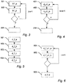
- the method starts in step 101 with obtaining a plurality of candidate first lattice plane normal vector and a plurality of candidate second lattice plane normal vectors for a particular grain.
- the candidate first and second lattice plane normal vectors are 3D vectors that may be generated by a pseudo random number generator (PRNG).
- PRNG pseudo random number generator
- the primary candidate unit cell PCUC is validated by evaluating the fit of the PCUC with the full set DV of 3D diffraction vectors.
- step B 102 it is determined if the fit of the primary candidate unit cell PCUC with the full set DV of 3D diffraction vectors is above a first threshold. If the fit is above the first threshold the method continues to step 103 where the primary candidate unit cell PCUC is used to identify a subset ST of the set DV of 3D diffraction vectors originating from a single grain. The subset ST is then indexed and removed from the set DV of 3D diffraction vectors and the method continues to step 104.
- step 104 the method determines if a first predetermined criteria has been reached.
- a predetermined criteria are: that all indexable grains in the poly-crystal sample have been indexed, that a predetermined number of grains have been indexed, that a predetermined percentage of the diffraction vectors has been indexed, that the remaining diffraction vectors is below a predetermined number, or that step (A) and (B) have been repeated a predetermined number of times without identifying any new grains. If the predetermined criteria has not yet been reached the method returns to step A to look for a new primary candidate unit cell PCUC. Alternatively, if the predetermined criteria have been reached the method terminates in step 105.
- Figs. 2 shows a flowchart for a first part of a method according to an embodiment of the present invention. Specifically Fig. 2 shows how step A in the method disclosed in relation to Fig. 1 may be carried out.
- a set L1 of candidate first lattice plane normal vectors are selected.
- the set L1 may be selected using a PRNG.
- step 202 the fit of each candidate first lattice plane normal vector of the set L1 with the set DV of 3D diffraction vectors is evaluated.
- step 204 for each individual candidate first lattice plane normal vector of the subset SL1 steps 205-211 are performed.
- step 206 a set L2_n of candidate second lattice plane normal vectors is selected.
- the set L2_n may be selected using a PRNG.
- step 207 the fit of each candidate second lattice plane normal vector of the set L2_n with the subset SDV_n of 3D diffraction vectors is evaluated.
- a subset SL2_n of the set L2_n is selected comprising the N2 candidate second lattice plane normal vectors having the best fit with the subset SDV_n of 3D diffraction vectors.
- the subset SL2_n of candidate second lattice plane normal vectors is used to select a subset SSDV_n of the subset SDV_n of 3D diffraction vectors.
- the subset SSDV_n of 3D diffraction vectors is then in step 210 processed to determine a candidate unit cell CUC_n defined by three lattice vectors, and finally in step 211 the fit of the candidate unit cell CUC_n with the set full set DV of 3D diffraction vectors is evaluated.
- the method then returns to step 205 if n is below N1 and increases n by 1.
- Figs. 3 shows a flowchart for a second part of a method according to an embodiment of the present invention. Specifically Fig. 3 shows an example of how step 202 in the method disclosed in relation to Fig. 2 may be carried out.
- step 302 the set DV1D_j of projected 1D diffraction vectors is filtered with a plurality of filters comprising a regular array of box functions, the width of the boxes being the same for all filter but the distance 'd' between the boxes is increased from a value d_min to a value d_max (in increasingly larger steps), the output of each filtering process K is the normalised number of projected 1D diffraction vectors that are positioned within a box function, wherein the highest K value is used as a measure of the fit of the j'th candidate first lattice plane normal vector with the set DV of 3D diffraction vectors.
- the method then returns to step 301 if j is below N1 (N1 being equal to the number of candidate first lattice plane normal vectors in the set L1) and increases n by 1. Alternatively, if j is equal to N1 (meaning that steps 201 and 202 have been performed for each candidate first lattice plane normal vector of the set L1) the method continues to step 203 in Fig. 2 .
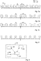
- Figs. 7a-b illustrates schematically the filtering process.
- 23 diffraction vectors originating from a first grain and a second grain are present.
- the terminal point for the projected 1D diffraction vectors originating from the first grain are shown as boxes 701 and the terminal point of the projected 1D diffractions vectors originating from the second grain are shown as crosses 702.
- the 23 3D diffraction vectors are in Figs.
- the projected 1D diffraction vectors originating from the first grain are arranged with a regular spacing
- the projected 1D diffraction vectors originating from the second grain are arranged with an irregular spacing.
- Fig. 7b illustrates a second filtering process. Shown is a regular array of box functions 703 having a width w and being arranged with a distance 'd_2'. The width w is the same for both filtering process but 'd_2' is larer than 'd_1'. For this filtering process the distance 'd_2' between the boxes matches the regular spacing between 1D diffraction vectors originating from the first grain.
- Fig. 7c shows the 23 3D diffraction vectors projected onto a candidate lattice plane normal vector that is non-identical to any one of the three true lattice plane normal vectors for both the first and the second grain. Consequently, the projected 1D diffraction vectors originating from the both the first and the second grain are arranged with an irregular spacing.
- a method based on frequency analysis may be used to evaluate the fit of each candidate lattice plane normal vector. This may be done by sampling the project 1d diffraction vectors to create a sampled signal, and determining the amplitude spectrum for the sampled signal. By studying the amplitude spectrum in the frequency range between 1/d_max to 1/d_min the fit of the candidate lattice plane normal vectors with the set DV of 3D diffraction vectors may be determined e.g. by examining the peak amplitude within that frequency range.
- Fig. 8 shows the subset of the projected 23 diffraction vectors shown in Fig. 7a-b that are positioned within a box function for the filter having the highest K value (the filter shown in Fig. 7b ).
- the set SDV_n1D_k of projected 1D diffraction vectors is filtered with a plurality of filters comprising a regular array of box functions, the width of the boxes being the same for all filter but the distance 'd' between the boxes is increased from a value d_min to a value d_max (in increasingly larger steps), the output of each filtering process K is the normalized number of projected 1D diffraction vectors that are positioned within a box function, wherein the highest K value is used as a measure of the fit of the k'th candidate second lattice plane normal vector with the set SDV_n of 3D diffraction vectors.
- the filtering process may be performed using the same principles disclosed in relation to Fig. 7 .
- the method then returns to step 401 if k is below N2 (N2 being equal to the number of candidate second lattice plane normal vectors in the set L2_n) and increases k by 1. Alternatively, if k is equal to N2 (meaning that steps 301 and 302 have been performed for each candidate second lattice plane normal vector of the set L2_n) the method continues to step 208 in Fig. 2 .
- Figs. 5 shows a flowchart for a fourth part of a method according to an embodiment of the present invention. Specifically Fig. 5 shows an example of how step 210 in the method disclosed in relation to Fig. 2 may be carried out.
- the method starts in step 501 with selecting a subset SSSDV_n of the subset SSDV_n of 3D diffraction vectors.
- the subset SSSDV_n may comprise the 50 shortest diffraction vectors of the subset SSDV_n of 3D diffraction vectors.
- step 502 the normal vector for all planes spanned by three diffraction vectors of the subset SSSDV_n of 3D diffraction vectors (ignoring sets of three diffraction vectors having a cross product close to zero) are determined. Since each normal vector is a candidate lattice plane normal vector this result in a set NL_n of new candidate lattice plane normal vectors.
- step 503 the fit of each new candidate lattice plane normal vector of the set NL_n with the subset SSDV_n of 3D diffraction vectors is evaluated, and finally in step 504 a candidate unit cell CUC_n is determined.
- the method then continues to step 212 in Fig. 2 .
- Fig. 6 shows a flowchart for a fifth part of a method according to an embodiment of the present invention. Specifically Fig. 6 shows an example of how steps 503 and 504 in the method disclosed in relation to Fig. 5 may be carried out.
- step 602 the set SSDV_n_1D_i of projected 1D diffraction vectors is filtered with a plurality of filters comprising a regular array of box functions, the width of the boxes being the same for all filter but the distance 'd' between the boxes is increased between a value d_min and a value d_max, the output of each filtering process K is the number of projected 1D diffraction vectors that are positioned within a box function, wherein the K value for the filter having the largest distance 'd*' between the boxes while maintaining a K value being at least X% of the maximum K value for all filters is selected as a measure F of the fit of the i'th new candidate lattice plane normal vector with the subset SSDV_n of 3D diffraction vectors, and wherein the vector pointing along the i'th new candidate lattice plane normal vector and having the length 1/'d*' is selected as a candidate direct-lattice vector.
- the method then returns to step 601 if i is below N4 (N4 being equal to the number of new candidate lattice plane normal vector of the set NL_n) and increases i by 1. Alternatively, if i is equal to N4 (meaning that steps 601 and 602 have been performed for each new candidate lattice plane normal vector of the set NL_n) the method continues to step 603. This result in a set CDLV_n of candidate direct-lattice vectors comprising N4 candidate direct-lattice vectors. In the 603, three linear independent candidate direct-lattice vectors of the set CDLV_n is selected as the candidate unit cell CUC_n based on their respective F values.
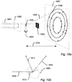
- Fig. 9 shows a schematic drawing of an X-ray diffraction apparatus 901 for analysing a poly-crystalline sample according to an embodiment of the present invention.
- the X-ray diffraction apparatus comprises:
- Figs. 10a-b show schematically how diffraction spots may be recorded and transformed into diffraction vectors.
- the set of diffraction vectors can be determined in a number of ways. The most commonly used is the "ro-method" known from single-crystal crystallography [9] in which case the sample to detector distance 1013 is sufficiently large that all grains can be considered to be located at the origin of the sample (i.e. a far-field configuration).
- a monochromatic x-ray beam 1001 is illuminating the sample 1005 through an aperture 1002 and a beam stop 1004 and a detector 1007 is provided behind the sample 1005.
- the sample 1005 is mounted on a rotation stage with one or more rotational axes 1003.
- the sample is rotated around a single axis 1003 perpendicular to the incoming beam as illustrated in Fig. 10a .
- x, y and z translations may be added, as well as additional rotations.
- Any part of the illuminated structure which fulfills the Bragg condition 1012 e.g. a lattice plane
- the diffraction vectors 1011 are derived from knowledge of the incoming beam direction 1009 and the directional vectors 1010 from the sample origin to the measure diffraction spots on the detector(s) 1007 (See Fig. 10b ).
- Other examples of experimental methods for measuring diffractions vectors include monochromatic near-field configurations such as those described in [10], and [11], as well as polychromatic configurations (see e.g. [12] and [13]).
Landscapes
- Chemical & Material Sciences (AREA)
- Crystallography & Structural Chemistry (AREA)
- Physics & Mathematics (AREA)
- Health & Medical Sciences (AREA)
- Life Sciences & Earth Sciences (AREA)
- Analytical Chemistry (AREA)
- Biochemistry (AREA)
- General Health & Medical Sciences (AREA)
- General Physics & Mathematics (AREA)
- Immunology (AREA)
- Pathology (AREA)
- Analysing Materials By The Use Of Radiation (AREA)
Claims (15)
- Verfahren zum Bestimmen einer oder mehrerer Einheitszellen einer polykristallinen Probe und Indexieren einer Menge DV von 3D-Beugungsvektoren, die durch Bestrahlen der polykristallinen Probe mit einer Röntgenquelle in einer oder mehreren Orientierungen erhalten werden, und Aufzeichnen von Beugungspunkten unter Verwendung wenigstens eines 2D-Röntgendetektors oder 3D-Röntgendetektors, wobei der 3D-Röntgendetektor ein Detektor ist, der für jede der einen oder mehreren Orientierungen unterschiedliche Röntgenenergien trennen kann, wobei die Menge DV von 3D-Beugungsvektoren in mehrere Körner indexiert wird, wobei das Verfahren die folgenden Schritte umfasst:(A) Erhalten mehrerer erster Kandidatengitterebenennormalenvektoren und mehrerer zweiter Kandidatengitterebenennormalenvektoren für ein spezielles unbekanntes Korn; Verwenden der mehreren ersten Kandidatengitterebenennormalenvektoren und der mehreren zweiten Kandidatengitterebenennormalenvektoren um mehrere Teilmengen SSDV n der Menge DV von 3D-Beugungsvektoren auszuwählen, und Verarbeiten der mehreren Teilmengen SSDV_n von 3D-Beugungsvektoren, um eine primäre Kandidateneinheitszelle PCUC, die durch drei Gittervektoren definiert ist, zu bestimmen; wobei die Zuordnung der primären Kandidateneinheitszelle PCUC durch Bewerten der Übereinstimmung der PCUC mit der vollständigen Menge DV der 3D-Beugungsvektoren validiert wird; und(B) Bestimmen, ob die Übereinstimmung der primären Kandidateneinheitszelle PCUC mit der vollständigen Menge von 3D-Beugungsvektoren oberhalb eines ersten Schwellenwerts ist;
wobei dann, wenn die Übereinstimmung der primären Kandidateneinheitszelle PCUC oberhalb des ersten Schwellenwerts ist, die primäre Kandidateneinheitszelle PCUC verwendet wird, um eine Teilmenge ST der Menge DV von 3D-Beugungsvektoren, die von einem einzelnen Korn in der polykristallinen Probe herrühren, zu identifizieren, die Teilmenge ST indexiert wird, wobei das Verfahren zu Schritt (A) zurückkehrt, sofern nicht ein vorgegebenes Kriterium erreicht worden ist. - Verfahren nach Anspruch 1, wobei Schritt (A) die folgenden Schritte umfasst:(a) Auswählen einer Menge L1 von ersten Kandidatengitterebenennormalenvektoren;(b) Bewerten der Übereinstimmung jedes ersten Kandidatengitterebenennormalenvektors der Menge L1 mit der Menge DV von 3D-Beugungsvektoren;(c) Auswählen einer Teilmenge SL1 der Menge L1, die die N1 ersten Kandidatengitterebenennormalenvektoren, die die beste Übereinstimmung mit der Menge DV der 3D-Beugungsvektoren aufweisen, umfasst;(d) Ausführen der Schritte (d_a) bis (d_g) für jeden ersten Kandidatengitterebenennormalenvektor n der Teilmenge SL1:(d_a) Verwenden des ersten Kandidatengitterebenennormalenvektors n, um eine Teilmenge SDV_n der Menge DV von Beugungsvektoren auszuwählen;(d_b) Auswählen einer Menge L2 n von zweiten Kandidatengitterebenennormalenvektoren;(d_c) Bewerten der Übereinstimmung jedes zweiten Kandidatengitterebenennormalenvektors der Menge L2_n mit der Teilmenge SDV_n von 3D-Beugungsvektoren;(d_d) Auswählen einer Teilmenge SL2_n der Menge L2_n, die die N2 zweiten Kandidatengitterebenennormalenvektoren, die die beste Übereinstimmung mit der Teilmenge SDV_n von 3D-Beugungsvektoren aufweisen, umfasst;(d_e) Verwenden der Teilmenge SL2_n von zweiten Kandidatengitterebenennormalenvektoren, um eine Teilmenge SSDV_n der Teilmenge SDV_n von 3D-Beugungsvektoren auszuwählen;(d_f) Verarbeiten der Teilmenge SSDV_n von 3D-Beugungsvektoren, um eine Kandidateneinheitszelle CUC_n, die durch drei Gittervektoren definiert ist, zu bestimmen;(d_g) Bewerten der Übereinstimmung der Kandidateneinheitszelle CUC_n mit der Menge DV von 3D-Beugungsvektoren;
wobei die Kandidateneinheitszelle aus den N1 Kandidateneinheitszellen CUC n (n = 1 bis N1), die die beste Übereinstimmung mit der vollständigen Menge DV von 3D-Beugungsvektoren aufweist, als die primäre Kandidateneinheitszelle PCUC ausgewählt wird. - Verfahren nach Anspruch 2, wobei der Schritt (b) die folgenden Schritte umfasst:
(b1) Ausführen der Schritte (b1_a) und (b1_b) für jeden j ersten Kandidatengitterebenennormalenvektor der Menge L1:(b1_a) Projizieren der Menge DV von 3D-Beugungsvektoren auf den j ersten Kandidatengitterebenennormalenvektor, was zu einer Menge DV1D_j projizierter 1D-Beugungsvektoren führt;(b1_b) Filtern der Menge DV1D_j von projizierten 1D-Beugungsvektoren mit mehreren Filtern, die eine regelmäßige Anordnung von Rechteckfunktionen umfassen, wobei die Breite der Rechtecke für alle Filter gleich ist, jedoch der Abstand 'd' zwischen den Rechtecken von einem Wert d_min zu einem Wert d_max erhöht wird, wobei die Ausgabe jedes Filterprozesses K die normalisierte Anzahl projizierter 1D-Beugungsvektoren ist, die innerhalb einer Reckeckfunktion positioniert sind, wobei der höchste K-Wert als ein Maß der Übereinstimmung des n-ten ersten Kandidatengitterebenennormalenvektors mit der Menge DV von 3D-Beugungsvektoren verwendet wird; und wobei der Schritt (c) das Auswählen der N1 ersten Kandidatengitterebenennormalenvektoren, die den höchsten K-Wert aufweisen, umfasst. - Verfahren nach Anspruch 2 oder 3, wobei der Schritt (c) ferner für jeden n ersten Kandidatengitterebenennormalenvektor der Teilmenge SL1 das Optimieren des n ersten Kandidatengitterebenennormalenvektors durch Ausführen einer lokalen Rastersuche umfasst, die zu einer Teilmenge SL1* optimierter erster Kandidatengitterebenennormalenvektoren führt, wobei die optimierte Teilmenge SL1* in Schritt (d) verwendet wird.
- Verfahren nach einem der Ansprüche 2 bis 4, wobei der Schritt (d_c) die folgenden Schritte umfasst:
(d_c1) Ausführen der Schritte (d_c1_a) und (d_c1_b) für jeden k zweiten Kandidatengitterebenennormalenvektor der Menge L2_n:(d_c1_a) Projizieren der Teilmenge SDV n von 3D-Beugungsvektoren auf den k zweiten Kandidatengitterebenennormalenvektor, was zu einer Menge SDV_n1D_n projizierter 1D-Beugungsvektoren führt;(d_c1_b) Filtern der Menge SDV_n1D_k von projizierten 1D-Beugungsvektoren mit mehreren Filtern, die eine regelmäßige Anordnung von Rechteckfunktionen umfassen, wobei die Breite der Rechtecke für alle Filter gleich ist, jedoch der Abstand 'd' zwischen den Rechtecken von einem Wert d_min zu einem Wert d_max erhöht wird, wobei die Ausgabe jedes Filterprozesses K die normalisierte Anzahl projizierter 1D-Beugungsvektoren ist, die innerhalb einer Reckeckfunktion positioniert sind, wobei der höchste K-Wert als ein Maß der Übereinstimmung des k-ten zweiten Kandidatengitterebenennormalenvektors mit der Menge SDV_n von 3D-Beugungsvektoren verwendet wird; undwobei der Schritt (d_d) das Auswählen der N3 zweiten Kandidatengitterebenennormalenvektoren, die den höchsten K-Wert aufweisen, umfasst. - Verfahren nach einem der Ansprüche 2 bis 5, wobei der Schritt (d_d) ferner für jeden k zweiten Kandidatengitterebenennormalenvektor der Teilmenge SL2_n das Optimieren des k zweiten Kandidatengitterebenennormalenvektors durch Ausführen einer lokalen Rastersuche, die zu einer Teilmenge SL2_n* optimierter zweiter Kandidatengitterebenennormalenvektoren führt, umfasst, wobei die optimierte Teilmenge SL2_n* in Schritt (d_e) verwendet wird.
- Verfahren nach Anspruch 6, wobei der zweite Kandidatengitterebenennormalenvektor CL2_n der Teilmenge SL2_n*, der die beste Übereinstimmung mit der Teilmenge SDV_n von 3D-Beugungsvektoren aufweist, verwendet wird, um die Teilmenge SSDV_n der Teilmenge SDV_n von 3D-Beugungsvektoren auszuwählen.
- Verfahren nach einem der Ansprüche 2 bis 7, wobei der Schritt (d_e) das Auswählen der 3D-Beugungsvektoren der Teilmenge SDV_n, die dann, wenn sie auf CL2_n projiziert werden, innerhalb einer Rechteckfunktion für das Filter, den höchsten K-Wert aufweist, positioniert sind, umfasst.
- Verfahren nach einem der Ansprüche 2 bis 8, wobei der Schritt (d_f) die folgenden Schritte umfasst:(d_f_a) Auswählen einer Teilmenge SSSDV_n der Teilmenge SSDV_n von 3D-Beugungsvektoren;(d_f_b) Bestimmen des Normalenvektors für alle Ebenen, die durch drei Beugungsvektoren der Teilmenge SSSDV _n von 3D-Beugungsvektoren aufgespannt wird (wobei Mengen von drei Beugungsvektoren, die ein Kreuzprodukt nahe null aufweisen, ignoriert werden), wobei jeder Normalenvektor ein Kandidatengitterebenennormalenvektor ist, was dadurch zu einer Menge NL n neuer Kandidatengitterebenennormalenvektoren führt;(d_f_c) Bewerten der Übereinstimmung jedes neuen Kandidatengitterebenennormalenvektors der Menge NL_n mit der Teilmenge SSDV n von 3D-Beugungsvektoren; und(d_f_d) Bestimmen einer Kandidateneinheitszelle CUC_n.
- Verfahren nach Anspruch 9, wobei der Schritt (d_f_c) Folgendes umfasst:
(d_f_c1) Ausführen der Schritte (d_f_c1_a) und (d_f_c1_b) für jeden i neuen Kandidatengitterebenennormalenvektor der Menge NL n:(d_f_c1_a) Projizieren der Teilmenge SSDV_n von 3D-Beugungsvektoren auf den i neuen Kandidatengitterebenennormalenvektor, was zu einer Menge SSDV_n_1D_i von 1D-Beugungsvektoren führt;(d_f_c1_b) Filtern der Menge SSDV_n_1D_i projizierter 1D-Beugungsvektoren mit mehreren Filtern, die eine regelmäßige Anordnung von Rechteckfunktionen umfassen, wobei die Breite der Rechtecke für alle Filter gleich ist, jedoch der Abstand 'd' zwischen den Rechtecken zwischen einem Wert d_min und einem Wert d_max vergrößert wird, die Ausgabe jedes Filterprozesses K die Anzahl projizierter 1D-Beugungsvektoren ist, die innerhalb der Rechteckfunktion positioniert sind, wobei der K-Wert für das Filter, das den größten Abstand 'd*' zwischen den Rechtecken aufweist, während ein K-Wert beibehalten wird, der wenigstens X % des maximalen K-Werts für alle Filter ist, als ein Maß F für die Übereinstimmung des i-ten neuen Kandidatengitterebenennormalenvektors mit der Teilmenge SSDV n von 3D-Beugungsvektoren ausgewählt wird, und wobei der Vektor, der entlang des i-ten neuen Kandidatengitterebenennormalenvektors zeigt und die Länge 1/'d*' aufweist, als ein Kandidatenrichtungsgittervektor ausgewählt wird, wodurch eine Menge CDLV_n von Kandidatenrichtungsgittervektoren erzeugt wird, undwobei der Schritt (d_f_d) Folgendes umfasst:
Auswählen von drei linear unabhängigen Kandidatenrichtungsgittervektoren der Menge CDLV n basierend auf ihren F-Werten als die Kandidateneinheitszelle CUC_n. - Verfahren zum Indexieren von mehreren Beugungspunkten, wobei das Verfahren die folgenden Schritte umfasst:Indexieren der Beugungsvektoren, die den mehreren Beugungspunkten entsprechen, unter Verwendung eines Verfahrens nach einem der Ansprüche 1 bis 10; undVerwenden der indexierten Beugungsvektoren, um die entsprechenden Beugungspunkte zu indexieren.
- Verfahren zum Bestimmen der Zusammensetzung einer polykristallinen Probe, das die folgenden Schritte umfasst:• Bestrahlen einer polykristallinen Probe mit einer Röntgenquelle in mehreren Orientierungen und Aufzeichnen von Beugungspunkten unter Verwendung eines 2D- oder 3D-Röntgendetektors für jede der mehreren Orientierungen;• Transformieren der aufgezeichneten Beugungspunkte in eine Menge DV von Beugungsvektoren;• Indexieren der Menge DV von Beugungsvektoren unter Verwendung eines Verfahrens nach einem er Ansprüche 1 bis 10; und• Verarbeiten der indexierten Beugungsvektoren, um die Zusammensetzung der polykristallinen Probe zu bestimmen.
- Röntgenbeugungseinrichtung zum Analysieren einer polykristallinen Probe, die Folgendes umfasst:eine Röntgenquelle zum Emittieren eines Röntgenstrahls;eine Objekttischvorrichtung zum Positionieren der polykristallinen Probe in dem Strahlenweg in mehreren wechselseitig unterschiedlichen Winkelpositionen relativ zu der Röntgenquelle;einen Röntgendetektor zum Detektieren gebeugter Röntgenstrahlen, die aus der polykristallinen Probe austreten, wobei der Detektor wenigstens ein 2D-Röntgendetektor oder 3D-Röntgendetektor ist, wobei der 3D-Röntgendetektor ein Detektor ist, der zum Trennen unterschiedlicher Röntgenenergien fähig ist; undeine Verarbeitungseinheit, die mit dem Röntgendetektor betriebstechnisch gekoppelt ist, wobei die Verarbeitungseinheit konfiguriert ist, eine Menge DV von 3D-Beugungsvektoren durch Verarbeiten von Daten, die aus dem Röntgendetektor empfangen werden und die durch Bestrahlen der polykristallinen Probe in mehreren Orientierungen erhalten werden, zu bestimmen;dadurch gekennzeichnet, dass die Verarbeitungseinheit ferner konfiguriert ist, die Menge DV von 3D-Beugungsvektoren unter Verwendung eines Verfahrens nach einem der Ansprüche 1 bis 10 zu indexieren.
- Computerprogrammprodukt, das Programmcodemittel umfasst, die ausgelegt sind, dann, wenn sie auf einer Datenverarbeitungseinheit ausgeführt werden, die Einrichtung nach Anspruch 13 zu veranlassen, die Schritte des Verfahrens nach einem der Ansprüche 1 bis 10 auszuführen.
- Nichttransitorisches computerlesbares Medium, auf dem das Computerprogrammprodukt nach Anspruch 14 gespeichert ist.
Priority Applications (4)
| Application Number | Priority Date | Filing Date | Title |
|---|---|---|---|
| EP15180196.6A EP3128317B1 (de) | 2015-08-07 | 2015-08-07 | Mehrkörnige röntgenstrahlkristallografie |
| US15/228,868 US10139357B2 (en) | 2015-08-07 | 2016-08-04 | X-ray multigrain crystallography |
| CN201610643281.1A CN106442582A (zh) | 2015-08-07 | 2016-08-08 | X射线多粒晶体学 |
| US16/182,091 US10288570B2 (en) | 2015-08-07 | 2018-11-06 | X-ray multigrain crystallography |
Applications Claiming Priority (1)
| Application Number | Priority Date | Filing Date | Title |
|---|---|---|---|
| EP15180196.6A EP3128317B1 (de) | 2015-08-07 | 2015-08-07 | Mehrkörnige röntgenstrahlkristallografie |
Publications (2)
| Publication Number | Publication Date |
|---|---|
| EP3128317A1 EP3128317A1 (de) | 2017-02-08 |
| EP3128317B1 true EP3128317B1 (de) | 2022-01-05 |
Family
ID=53785554
Family Applications (1)
| Application Number | Title | Priority Date | Filing Date |
|---|---|---|---|
| EP15180196.6A Active EP3128317B1 (de) | 2015-08-07 | 2015-08-07 | Mehrkörnige röntgenstrahlkristallografie |
Country Status (3)
| Country | Link |
|---|---|
| US (2) | US10139357B2 (de) |
| EP (1) | EP3128317B1 (de) |
| CN (1) | CN106442582A (de) |
Families Citing this family (4)
| Publication number | Priority date | Publication date | Assignee | Title |
|---|---|---|---|---|
| EP3435161A1 (de) * | 2017-07-24 | 2019-01-30 | ASML Netherlands B.V. | Bestimmung eines kantenrauheitsparameters einer periodischen struktur |
| WO2019213966A1 (zh) * | 2018-05-11 | 2019-11-14 | 深圳晶泰科技有限公司 | 一种晶体粉末衍射的指标化方法 |
| CN114486965B (zh) * | 2021-06-29 | 2024-01-30 | 中国科学技术大学 | 一种测量表面法向衍射信号的方法、装置及存储介质 |
| JP7578288B2 (ja) * | 2021-12-22 | 2024-11-06 | パルステック工業株式会社 | X線回折測定装置及びx線回折像を用いた演算方法 |
Family Cites Families (9)
| Publication number | Priority date | Publication date | Assignee | Title |
|---|---|---|---|---|
| US7469036B2 (en) * | 2002-04-19 | 2008-12-23 | Los Alamos National Security, Llc | Analysis of macromolecules, ligands and macromolecule-ligand complexes |
| JP3931161B2 (ja) * | 2003-08-05 | 2007-06-13 | 株式会社リガク | X線構造解析における回折斑点の強度算出方法 |
| CN100545644C (zh) * | 2005-09-02 | 2009-09-30 | 中国科学院金属研究所 | 一种半自动x射线晶面指数标定和晶胞常数计算的方法 |
| JP4908303B2 (ja) * | 2007-04-26 | 2012-04-04 | 株式会社リガク | X線単結晶方位測定装置およびその測定方法 |
| US8131481B2 (en) * | 2007-05-03 | 2012-03-06 | State Of Oregon Acting By And Through The State Board Of Higher Education On Behalf Of Portland State University | Database supported nanocrystal structure identification by lattice-fringe fingerprinting with structure factor extraction |
| CN101813643B (zh) * | 2010-04-13 | 2012-05-23 | 中南大学 | 一种烧结炉炉内气氛中s杂质含量水平的标定方法 |
| US9222900B2 (en) * | 2013-03-05 | 2015-12-29 | Danmarks Tekniske Universitet Of Anker Engelundsvej | X-ray diffraction method of mapping grain structures in a crystalline material sample, and an X-ray diffraction apparatus |
| US9222901B2 (en) * | 2013-03-05 | 2015-12-29 | Danmarks Tekniske Universitet Anker Engelundsvej | X-ray diffraction method of mapping grain structures in a crystalline material sample, and an X-ray diffraction apparatus |
| CN104155324A (zh) * | 2014-07-31 | 2014-11-19 | 陕西大仪科技有限责任公司 | 一种确定单晶三维方向的方法 |
-
2015
- 2015-08-07 EP EP15180196.6A patent/EP3128317B1/de active Active
-
2016
- 2016-08-04 US US15/228,868 patent/US10139357B2/en active Active
- 2016-08-08 CN CN201610643281.1A patent/CN106442582A/zh active Pending
-
2018
- 2018-11-06 US US16/182,091 patent/US10288570B2/en active Active
Also Published As
| Publication number | Publication date |
|---|---|
| CN106442582A (zh) | 2017-02-22 |
| US20170038317A1 (en) | 2017-02-09 |
| EP3128317A1 (de) | 2017-02-08 |
| US10288570B2 (en) | 2019-05-14 |
| US10139357B2 (en) | 2018-11-27 |
| US20190079032A1 (en) | 2019-03-14 |
Similar Documents
| Publication | Publication Date | Title |
|---|---|---|
| US10288570B2 (en) | X-ray multigrain crystallography | |
| Randau et al. | StressTextureCalculator: a software tool to extract texture, strain and microstructure information from area-detector measurements | |
| Tamura | XMAS: A versatile tool for analyzing synchrotron X-ray microdiffraction data | |
| Sharma et al. | A fast methodology to determine the characteristics of thousands of grains using three-dimensional X-ray diffraction. II. Volume, centre-of-mass position, crystallographic orientation and strain state of grains | |
| Manceau et al. | Estimating the number of pure chemical components in a mixture by X-ray absorption spectroscopy | |
| Borbély et al. | X-ray line profiles analysis of plastically deformed metals | |
| DiPompeo et al. | Updated measurements of the dark matter halo masses of obscured quasars with improved WISE and Planck data | |
| Poulsen | Multi scale hard x-ray microscopy | |
| Kotula et al. | Focused ion beam and scanning electron microscopy for 3D materials characterization | |
| Zendler et al. | VITESS 3–virtual instrumentation tool for the European spallation source | |
| Wei et al. | 3D nanostructural characterisation of grain boundaries in atom probe data utilising machine learning methods | |
| Jeong et al. | Probing core-electron orbitals by scanning transmission electron microscopy and measuring the delocalization of core-level excitations | |
| Nakashima | Quantitative convergent-beam electron diffraction and quantum crystallography—the metallic bond in aluminium | |
| KR20130133685A (ko) | 제조 툴에 대한 레시피를 생성하는 방법 및 그 시스템 | |
| WO2015136931A1 (ja) | 導電率分布導出方法および導電率分布導出装置 | |
| Tischler | Reconstructing 2D and 3D X-ray orientation maps from white-beam Laue | |
| Hubert et al. | Structure refinement from ‘digital’large angle convergent beam electron diffraction patterns | |
| US20060206278A1 (en) | Apparatus and method for correcting for abberations | |
| Fang et al. | Forward-model-based grain reconstruction to improve the tolerance of diffraction contrast tomography for increased sample deformation | |
| Wejdemann et al. | Multigrain indexing of unknown multiphase materials | |
| Payne et al. | Multi-frequency study of extragalactic supernova remnants and HII regions-Sculptor group Sd galaxy NGC 300 | |
| Kolokythas et al. | The MeerKAT Galaxy Cluster Legacy Survey–II. Catalogue of the diffuse radio emission in MeerKAT-GCLS clusters | |
| EP2718665A1 (de) | Verfahren und vorrichtung zur charakterisierung von oberflächen | |
| Ball et al. | Implementing and evaluating far-field 3D X-ray diffraction at the I12 JEEP beamline, Diamond Light Source | |
| Nishimichi et al. | Simulating the anisotropic clustering of luminous red galaxies with subhaloes: a direct confrontation with observation and cosmological implications |
Legal Events
| Date | Code | Title | Description |
|---|---|---|---|
| PUAI | Public reference made under article 153(3) epc to a published international application that has entered the european phase |
Free format text: ORIGINAL CODE: 0009012 |
|
| STAA | Information on the status of an ep patent application or granted ep patent |
Free format text: STATUS: THE APPLICATION HAS BEEN PUBLISHED |
|
| AK | Designated contracting states |
Kind code of ref document: A1 Designated state(s): AL AT BE BG CH CY CZ DE DK EE ES FI FR GB GR HR HU IE IS IT LI LT LU LV MC MK MT NL NO PL PT RO RS SE SI SK SM TR |
|
| AX | Request for extension of the european patent |
Extension state: BA ME |
|
| STAA | Information on the status of an ep patent application or granted ep patent |
Free format text: STATUS: REQUEST FOR EXAMINATION WAS MADE |
|
| RBV | Designated contracting states (corrected) |
Designated state(s): AL AT BE BG CH CY CZ DE DK EE ES FI FR GB GR HR HU IE IS IT LI LT LU LV MC MK MT NL NO PL PT RO RS SE SI SK SM TR |
|
| 17P | Request for examination filed |
Effective date: 20170808 |
|
| REG | Reference to a national code |
Ref country code: DE Ref legal event code: R079 Ref document number: 602015076194 Country of ref document: DE Free format text: PREVIOUS MAIN CLASS: G01N0023205000 Ipc: G01N0023205500 |
|
| RIC1 | Information provided on ipc code assigned before grant |
Ipc: G01N 23/2055 20180101AFI20210504BHEP |
|
| GRAP | Despatch of communication of intention to grant a patent |
Free format text: ORIGINAL CODE: EPIDOSNIGR1 |
|
| STAA | Information on the status of an ep patent application or granted ep patent |
Free format text: STATUS: GRANT OF PATENT IS INTENDED |
|
| INTG | Intention to grant announced |
Effective date: 20210714 |
|
| RAP3 | Party data changed (applicant data changed or rights of an application transferred) |
Owner name: XNOVO TECHNOLOGY APS |
|
| GRAS | Grant fee paid |
Free format text: ORIGINAL CODE: EPIDOSNIGR3 |
|
| GRAA | (expected) grant |
Free format text: ORIGINAL CODE: 0009210 |
|
| STAA | Information on the status of an ep patent application or granted ep patent |
Free format text: STATUS: THE PATENT HAS BEEN GRANTED |
|
| AK | Designated contracting states |
Kind code of ref document: B1 Designated state(s): AL AT BE BG CH CY CZ DE DK EE ES FI FR GB GR HR HU IE IS IT LI LT LU LV MC MK MT NL NO PL PT RO RS SE SI SK SM TR |
|
| REG | Reference to a national code |
Ref country code: GB Ref legal event code: FG4D |
|
| REG | Reference to a national code |
Ref country code: CH Ref legal event code: EP |
|
| REG | Reference to a national code |
Ref country code: AT Ref legal event code: REF Ref document number: 1461015 Country of ref document: AT Kind code of ref document: T Effective date: 20220115 |
|
| REG | Reference to a national code |
Ref country code: DE Ref legal event code: R096 Ref document number: 602015076194 Country of ref document: DE |
|
| REG | Reference to a national code |
Ref country code: IE Ref legal event code: FG4D |
|
| REG | Reference to a national code |
Ref country code: LT Ref legal event code: MG9D |
|
| REG | Reference to a national code |
Ref country code: NL Ref legal event code: MP Effective date: 20220105 |
|
| REG | Reference to a national code |
Ref country code: AT Ref legal event code: MK05 Ref document number: 1461015 Country of ref document: AT Kind code of ref document: T Effective date: 20220105 |
|
| PG25 | Lapsed in a contracting state [announced via postgrant information from national office to epo] |
Ref country code: NL Free format text: LAPSE BECAUSE OF FAILURE TO SUBMIT A TRANSLATION OF THE DESCRIPTION OR TO PAY THE FEE WITHIN THE PRESCRIBED TIME-LIMIT Effective date: 20220105 |
|
| PG25 | Lapsed in a contracting state [announced via postgrant information from national office to epo] |
Ref country code: SE Free format text: LAPSE BECAUSE OF FAILURE TO SUBMIT A TRANSLATION OF THE DESCRIPTION OR TO PAY THE FEE WITHIN THE PRESCRIBED TIME-LIMIT Effective date: 20220105 Ref country code: RS Free format text: LAPSE BECAUSE OF FAILURE TO SUBMIT A TRANSLATION OF THE DESCRIPTION OR TO PAY THE FEE WITHIN THE PRESCRIBED TIME-LIMIT Effective date: 20220105 Ref country code: PT Free format text: LAPSE BECAUSE OF FAILURE TO SUBMIT A TRANSLATION OF THE DESCRIPTION OR TO PAY THE FEE WITHIN THE PRESCRIBED TIME-LIMIT Effective date: 20220505 Ref country code: NO Free format text: LAPSE BECAUSE OF FAILURE TO SUBMIT A TRANSLATION OF THE DESCRIPTION OR TO PAY THE FEE WITHIN THE PRESCRIBED TIME-LIMIT Effective date: 20220405 Ref country code: LT Free format text: LAPSE BECAUSE OF FAILURE TO SUBMIT A TRANSLATION OF THE DESCRIPTION OR TO PAY THE FEE WITHIN THE PRESCRIBED TIME-LIMIT Effective date: 20220105 Ref country code: HR Free format text: LAPSE BECAUSE OF FAILURE TO SUBMIT A TRANSLATION OF THE DESCRIPTION OR TO PAY THE FEE WITHIN THE PRESCRIBED TIME-LIMIT Effective date: 20220105 Ref country code: ES Free format text: LAPSE BECAUSE OF FAILURE TO SUBMIT A TRANSLATION OF THE DESCRIPTION OR TO PAY THE FEE WITHIN THE PRESCRIBED TIME-LIMIT Effective date: 20220105 Ref country code: BG Free format text: LAPSE BECAUSE OF FAILURE TO SUBMIT A TRANSLATION OF THE DESCRIPTION OR TO PAY THE FEE WITHIN THE PRESCRIBED TIME-LIMIT Effective date: 20220405 |
|
| PG25 | Lapsed in a contracting state [announced via postgrant information from national office to epo] |
Ref country code: PL Free format text: LAPSE BECAUSE OF FAILURE TO SUBMIT A TRANSLATION OF THE DESCRIPTION OR TO PAY THE FEE WITHIN THE PRESCRIBED TIME-LIMIT Effective date: 20220105 Ref country code: LV Free format text: LAPSE BECAUSE OF FAILURE TO SUBMIT A TRANSLATION OF THE DESCRIPTION OR TO PAY THE FEE WITHIN THE PRESCRIBED TIME-LIMIT Effective date: 20220105 Ref country code: GR Free format text: LAPSE BECAUSE OF FAILURE TO SUBMIT A TRANSLATION OF THE DESCRIPTION OR TO PAY THE FEE WITHIN THE PRESCRIBED TIME-LIMIT Effective date: 20220406 Ref country code: FI Free format text: LAPSE BECAUSE OF FAILURE TO SUBMIT A TRANSLATION OF THE DESCRIPTION OR TO PAY THE FEE WITHIN THE PRESCRIBED TIME-LIMIT Effective date: 20220105 Ref country code: AT Free format text: LAPSE BECAUSE OF FAILURE TO SUBMIT A TRANSLATION OF THE DESCRIPTION OR TO PAY THE FEE WITHIN THE PRESCRIBED TIME-LIMIT Effective date: 20220105 |
|
| PG25 | Lapsed in a contracting state [announced via postgrant information from national office to epo] |
Ref country code: IS Free format text: LAPSE BECAUSE OF FAILURE TO SUBMIT A TRANSLATION OF THE DESCRIPTION OR TO PAY THE FEE WITHIN THE PRESCRIBED TIME-LIMIT Effective date: 20220505 |
|
| REG | Reference to a national code |
Ref country code: DE Ref legal event code: R097 Ref document number: 602015076194 Country of ref document: DE |
|
| PG25 | Lapsed in a contracting state [announced via postgrant information from national office to epo] |
Ref country code: SM Free format text: LAPSE BECAUSE OF FAILURE TO SUBMIT A TRANSLATION OF THE DESCRIPTION OR TO PAY THE FEE WITHIN THE PRESCRIBED TIME-LIMIT Effective date: 20220105 Ref country code: SK Free format text: LAPSE BECAUSE OF FAILURE TO SUBMIT A TRANSLATION OF THE DESCRIPTION OR TO PAY THE FEE WITHIN THE PRESCRIBED TIME-LIMIT Effective date: 20220105 Ref country code: RO Free format text: LAPSE BECAUSE OF FAILURE TO SUBMIT A TRANSLATION OF THE DESCRIPTION OR TO PAY THE FEE WITHIN THE PRESCRIBED TIME-LIMIT Effective date: 20220105 Ref country code: EE Free format text: LAPSE BECAUSE OF FAILURE TO SUBMIT A TRANSLATION OF THE DESCRIPTION OR TO PAY THE FEE WITHIN THE PRESCRIBED TIME-LIMIT Effective date: 20220105 Ref country code: DK Free format text: LAPSE BECAUSE OF FAILURE TO SUBMIT A TRANSLATION OF THE DESCRIPTION OR TO PAY THE FEE WITHIN THE PRESCRIBED TIME-LIMIT Effective date: 20220105 Ref country code: CZ Free format text: LAPSE BECAUSE OF FAILURE TO SUBMIT A TRANSLATION OF THE DESCRIPTION OR TO PAY THE FEE WITHIN THE PRESCRIBED TIME-LIMIT Effective date: 20220105 |
|
| PLBE | No opposition filed within time limit |
Free format text: ORIGINAL CODE: 0009261 |
|
| STAA | Information on the status of an ep patent application or granted ep patent |
Free format text: STATUS: NO OPPOSITION FILED WITHIN TIME LIMIT |
|
| PG25 | Lapsed in a contracting state [announced via postgrant information from national office to epo] |
Ref country code: AL Free format text: LAPSE BECAUSE OF FAILURE TO SUBMIT A TRANSLATION OF THE DESCRIPTION OR TO PAY THE FEE WITHIN THE PRESCRIBED TIME-LIMIT Effective date: 20220105 |
|
| 26N | No opposition filed |
Effective date: 20221006 |
|
| PG25 | Lapsed in a contracting state [announced via postgrant information from national office to epo] |
Ref country code: SI Free format text: LAPSE BECAUSE OF FAILURE TO SUBMIT A TRANSLATION OF THE DESCRIPTION OR TO PAY THE FEE WITHIN THE PRESCRIBED TIME-LIMIT Effective date: 20220105 |
|
| PG25 | Lapsed in a contracting state [announced via postgrant information from national office to epo] |
Ref country code: MC Free format text: LAPSE BECAUSE OF FAILURE TO SUBMIT A TRANSLATION OF THE DESCRIPTION OR TO PAY THE FEE WITHIN THE PRESCRIBED TIME-LIMIT Effective date: 20220105 |
|
| REG | Reference to a national code |
Ref country code: CH Ref legal event code: PL |
|
| PG25 | Lapsed in a contracting state [announced via postgrant information from national office to epo] |
Ref country code: LU Free format text: LAPSE BECAUSE OF NON-PAYMENT OF DUE FEES Effective date: 20220807 Ref country code: LI Free format text: LAPSE BECAUSE OF NON-PAYMENT OF DUE FEES Effective date: 20220831 Ref country code: CH Free format text: LAPSE BECAUSE OF NON-PAYMENT OF DUE FEES Effective date: 20220831 |
|
| REG | Reference to a national code |
Ref country code: BE Ref legal event code: MM Effective date: 20220831 |
|
| PG25 | Lapsed in a contracting state [announced via postgrant information from national office to epo] |
Ref country code: IT Free format text: LAPSE BECAUSE OF FAILURE TO SUBMIT A TRANSLATION OF THE DESCRIPTION OR TO PAY THE FEE WITHIN THE PRESCRIBED TIME-LIMIT Effective date: 20220105 Ref country code: IE Free format text: LAPSE BECAUSE OF NON-PAYMENT OF DUE FEES Effective date: 20220807 |
|
| PG25 | Lapsed in a contracting state [announced via postgrant information from national office to epo] |
Ref country code: BE Free format text: LAPSE BECAUSE OF NON-PAYMENT OF DUE FEES Effective date: 20220831 |
|
| PG25 | Lapsed in a contracting state [announced via postgrant information from national office to epo] |
Ref country code: HU Free format text: LAPSE BECAUSE OF FAILURE TO SUBMIT A TRANSLATION OF THE DESCRIPTION OR TO PAY THE FEE WITHIN THE PRESCRIBED TIME-LIMIT; INVALID AB INITIO Effective date: 20150807 |
|
| PG25 | Lapsed in a contracting state [announced via postgrant information from national office to epo] |
Ref country code: CY Free format text: LAPSE BECAUSE OF FAILURE TO SUBMIT A TRANSLATION OF THE DESCRIPTION OR TO PAY THE FEE WITHIN THE PRESCRIBED TIME-LIMIT Effective date: 20220105 |
|
| PG25 | Lapsed in a contracting state [announced via postgrant information from national office to epo] |
Ref country code: MK Free format text: LAPSE BECAUSE OF FAILURE TO SUBMIT A TRANSLATION OF THE DESCRIPTION OR TO PAY THE FEE WITHIN THE PRESCRIBED TIME-LIMIT Effective date: 20220105 |
|
| PG25 | Lapsed in a contracting state [announced via postgrant information from national office to epo] |
Ref country code: MT Free format text: LAPSE BECAUSE OF FAILURE TO SUBMIT A TRANSLATION OF THE DESCRIPTION OR TO PAY THE FEE WITHIN THE PRESCRIBED TIME-LIMIT Effective date: 20220105 |
|
| PGFP | Annual fee paid to national office [announced via postgrant information from national office to epo] |
Ref country code: DE Payment date: 20240917 Year of fee payment: 10 |
|
| PGFP | Annual fee paid to national office [announced via postgrant information from national office to epo] |
Ref country code: GB Payment date: 20240913 Year of fee payment: 10 |
|
| PGFP | Annual fee paid to national office [announced via postgrant information from national office to epo] |
Ref country code: FR Payment date: 20240917 Year of fee payment: 10 |
|
| PG25 | Lapsed in a contracting state [announced via postgrant information from national office to epo] |
Ref country code: TR Free format text: LAPSE BECAUSE OF FAILURE TO SUBMIT A TRANSLATION OF THE DESCRIPTION OR TO PAY THE FEE WITHIN THE PRESCRIBED TIME-LIMIT Effective date: 20220105 |
|
| REG | Reference to a national code |
Ref country code: DE Ref legal event code: R119 Ref document number: 602015076194 Country of ref document: DE |